EP1978217A1 - Exhaust device for motorcycle - Google Patents
Exhaust device for motorcycle Download PDFInfo
- Publication number
- EP1978217A1 EP1978217A1 EP08251041A EP08251041A EP1978217A1 EP 1978217 A1 EP1978217 A1 EP 1978217A1 EP 08251041 A EP08251041 A EP 08251041A EP 08251041 A EP08251041 A EP 08251041A EP 1978217 A1 EP1978217 A1 EP 1978217A1
- Authority
- EP
- European Patent Office
- Prior art keywords
- exhaust
- throttle valve
- chamber
- pipe
- exhaust pipe
- Prior art date
- Legal status (The legal status is an assumption and is not a legal conclusion. Google has not performed a legal analysis and makes no representation as to the accuracy of the status listed.)
- Granted
Links
Images



Classifications
-
- F—MECHANICAL ENGINEERING; LIGHTING; HEATING; WEAPONS; BLASTING
- F01—MACHINES OR ENGINES IN GENERAL; ENGINE PLANTS IN GENERAL; STEAM ENGINES
- F01N—GAS-FLOW SILENCERS OR EXHAUST APPARATUS FOR MACHINES OR ENGINES IN GENERAL; GAS-FLOW SILENCERS OR EXHAUST APPARATUS FOR INTERNAL-COMBUSTION ENGINES
- F01N13/00—Exhaust or silencing apparatus characterised by constructional features
- F01N13/08—Other arrangements or adaptations of exhaust conduits
-
- F—MECHANICAL ENGINEERING; LIGHTING; HEATING; WEAPONS; BLASTING
- F01—MACHINES OR ENGINES IN GENERAL; ENGINE PLANTS IN GENERAL; STEAM ENGINES
- F01N—GAS-FLOW SILENCERS OR EXHAUST APPARATUS FOR MACHINES OR ENGINES IN GENERAL; GAS-FLOW SILENCERS OR EXHAUST APPARATUS FOR INTERNAL-COMBUSTION ENGINES
- F01N13/00—Exhaust or silencing apparatus characterised by constructional features
- F01N13/009—Exhaust or silencing apparatus characterised by constructional features having two or more separate purifying devices arranged in series
-
- F—MECHANICAL ENGINEERING; LIGHTING; HEATING; WEAPONS; BLASTING
- F01—MACHINES OR ENGINES IN GENERAL; ENGINE PLANTS IN GENERAL; STEAM ENGINES
- F01N—GAS-FLOW SILENCERS OR EXHAUST APPARATUS FOR MACHINES OR ENGINES IN GENERAL; GAS-FLOW SILENCERS OR EXHAUST APPARATUS FOR INTERNAL-COMBUSTION ENGINES
- F01N2260/00—Exhaust treating devices having provisions not otherwise provided for
- F01N2260/14—Exhaust treating devices having provisions not otherwise provided for for modifying or adapting flow area or back-pressure
-
- F—MECHANICAL ENGINEERING; LIGHTING; HEATING; WEAPONS; BLASTING
- F01—MACHINES OR ENGINES IN GENERAL; ENGINE PLANTS IN GENERAL; STEAM ENGINES
- F01N—GAS-FLOW SILENCERS OR EXHAUST APPARATUS FOR MACHINES OR ENGINES IN GENERAL; GAS-FLOW SILENCERS OR EXHAUST APPARATUS FOR INTERNAL-COMBUSTION ENGINES
- F01N2340/00—Dimensional characteristics of the exhaust system, e.g. length, diameter or volume of the exhaust apparatus; Spatial arrangements of exhaust apparatuses
- F01N2340/04—Arrangement of the exhaust system relative to a vehicle or parts thereof
-
- F—MECHANICAL ENGINEERING; LIGHTING; HEATING; WEAPONS; BLASTING
- F01—MACHINES OR ENGINES IN GENERAL; ENGINE PLANTS IN GENERAL; STEAM ENGINES
- F01N—GAS-FLOW SILENCERS OR EXHAUST APPARATUS FOR MACHINES OR ENGINES IN GENERAL; GAS-FLOW SILENCERS OR EXHAUST APPARATUS FOR INTERNAL-COMBUSTION ENGINES
- F01N2390/00—Arrangements for controlling or regulating exhaust apparatus
- F01N2390/08—Arrangements for controlling or regulating exhaust apparatus using mechanical components only, e.g. actuated manually
-
- F—MECHANICAL ENGINEERING; LIGHTING; HEATING; WEAPONS; BLASTING
- F01—MACHINES OR ENGINES IN GENERAL; ENGINE PLANTS IN GENERAL; STEAM ENGINES
- F01N—GAS-FLOW SILENCERS OR EXHAUST APPARATUS FOR MACHINES OR ENGINES IN GENERAL; GAS-FLOW SILENCERS OR EXHAUST APPARATUS FOR INTERNAL-COMBUSTION ENGINES
- F01N2490/00—Structure, disposition or shape of gas-chambers
- F01N2490/18—Dimensional characteristics of gas chambers
-
- F—MECHANICAL ENGINEERING; LIGHTING; HEATING; WEAPONS; BLASTING
- F01—MACHINES OR ENGINES IN GENERAL; ENGINE PLANTS IN GENERAL; STEAM ENGINES
- F01N—GAS-FLOW SILENCERS OR EXHAUST APPARATUS FOR MACHINES OR ENGINES IN GENERAL; GAS-FLOW SILENCERS OR EXHAUST APPARATUS FOR INTERNAL-COMBUSTION ENGINES
- F01N2590/00—Exhaust or silencing apparatus adapted to particular use, e.g. for military applications, airplanes, submarines
- F01N2590/04—Exhaust or silencing apparatus adapted to particular use, e.g. for military applications, airplanes, submarines for motorcycles
Definitions
- the present invention relates to an exhaust device for a motorcycle, and in particular to an exhaust throttle valve arrangement structure advantageous to disturbance due to scattered stones or the like.
- an exhaust throttle valve is provided in the exhaust system of an engine to adjust an amount of exhaust flow according to operating conditions, thereby intending to reduce exhaust noise and to provide high power.
- Examples of provision of such an exhaust throttle valve include one in which the exhaust throttle valve is provided at a collecting portion disposed forward of an engine (see Japanese Utility Model Publication No. Hei 4-20983 ) and another one in which the exhaust throttle valve is provided at a collective exhaust pipe located near the front end of a muffler (see Japanese Patent Laid-open No. Hei 4-292534 ).
- the exhaust throttle valve Since the exhaust throttle valve is provided at the exhaust system, it is sometimes disposed close to a front wheel or a rear wheel or on the vehicle body lower portion close to the ground surface. If the exhaust throttle valve is located at any one of such position, it tends to undergo disturbance due to scattered stones or the like.
- a rotational arm or drive wire of the exhaust throttle valve is located on the lateral surface of a collective portion forward of the lower portion of an engine, that is, located rearward of and close to the front wheel.
- stones or the like scattered by the front wheel tend to cause disturbance.
- an exhaust device for a motorcycle comprising: a plurality of exhaust pipes connected to associated exhaust ports of a multi-cylinder engine; a collecting portion collecting the exhaust pipes at a position close to the lower portion of the engine; a rear exhaust pipe connected to the downstream side of the collecting portion; an exhaust chamber connected to the downstream side of the rear exhaust pipe; an exhaust outlet portion provided on the downstream side of the exhaust chamber; a muffler connected to the downstream side of the exhaust outlet portion; and an exhaust throttle valve disposed inside a passage of the rear exhaust pipe to change an amount of exhaust flow.
- the exhaust throttle valve is attached to the rear exhaust pipe at a position between the collecting portion disposed near the lower portion of the engine and the exhaust chamber disposed downstream of the collecting portion and connected thereto via the rear exhaust pipe. Therefore, the exhaust throttle valve is surrounded by the collecting portion and the exhaust chamber so that it can be protected from disturbance due to stones or the like scattered by the front wheel or the like.
- a lateral width of the collecting portion is greater than a lateral width of the rear exhaust pipe including the exhaust throttle valve, as viewed from above.
- the collecting portion can protect the exhaust throttle valve against disturbance due to scattered stones or the like.
- the exhaust throttle valve can be protected from disturbance due to stones scattered from the front of the vehicle during running.
- the lateral width of the exhaust chamber is greater than that of the rear exhaust pipe including the exhaust throttle valve, as viewed from above.
- the exhaust throttle valve can be prevented from being hit by disturbance due to scattered stones bounced from the rear portion of the vehicle.
- the muffler is formed such that a vehicle-widthwise outside thereof is slanted to externally open toward the rearward.
- a back-and-forth length of a portion, of the exhaust throttle valve, disposed outside of the rear exhaust pipe is approximately equal to a back-and-forth length of the rear exhaust pipe.
- the collecting portion and exhaust chamber which are components larger than the exhaust throttle valve are disposed forward of and rearward of, respectively, the exhaust throttle valve with respect to the vehicle.
- the back-and-forth length of the rear exhaust pipe which corresponds to the interval between the collecting portion and the exhaust chamber is made approximately equal to the back-and-forth length of the exhaust throttle valve. Therefore, the back-and-forth interval of the exhaust throttle valve can be reduced by the collecting portion and by the exhaust chamber. This can prevent the exhaust throttle valve from being hit by disturbance due to scattered stones or the like.
- the exhaust throttle valve is disposed to recede from an external lateral portion of the collecting portion toward the inside of a vehicle body.
- the exhaust throttle valve can easily be protected from disturbance due to scattered stones or the like.
- a side stand during storage or an attachment portion overlaps the outside of the exhaust throttle valve as viewed from the side.
- the side stand during storage or the attachment portion is made to overlap the outside of the exhaust throttle valve. Therefore, the side stand during storage or the attachment portion covers the exhaust throttle valve from the externally lateral side thereof to protect it from disturbance due to scattered stones or the like.
- Fig. 1 is a lateral view of a motorcycle according to the embodiment.
- the motorcycle is such that a V-type water-cooled 4-cylinder engine 3 is disposed between a front wheel 1 and a rear wheel 2 and supported by a body frame 4.
- a hanger 5 is attached to the intermediate portion of the body frame 4 so as to support the front portion of the engine 3.
- a head pipe 6 is attached to the front end of the body frame 4 and a pivot plate 7 is supported by the rear portion of the body frame 4.
- a fuel tank 8 is supported on the intermediate portion of the body frame 4 and an air intake box 9 is received inside the front portion of the fuel tank 8.
- the air intake box 9 sucks air from front and supplies the air to front cylinders 10 and rear cylinders 11 located below the air intake box 9.
- the air intake box 9 is disposed above the valley portion between the front cylinders 10 and the rear cylinders 11.
- Front side exhaust pipes 12 extend forward from the respective front cylinders 10 and rear side exhaust pipes 13 extend rearward from the respective rear cylinders 11.
- the front side exhaust pipes 12 extend downward along the front surface of a crankcase 14 of the engine 3 and connect, from front, with a catalyst chamber 15 located below the crankcase 14, via a collecting pipe.
- the rear side exhaust pipes 13 connect, from front, with the catalyst chamber 15 via another collecting pipe as described later.
- the catalyst chamber 15 connects with an exhaust chamber 16, an expansion chamber, disposed rearward thereof.
- the exhaust chamber 16 is disposed in a space defined between the lower portion of the crankcase 14 and the rear wheel 2 and connects with a muffler 17 extending on the right side of the rear wheel 2 with respect to the vehicle body.
- the exhaust chamber 16 is supported by the lower end of the pivot plate 7 at two, front and rear, attachment portions 18, 19.
- the muffler 17 is disposed to cross a rear swing arm 20 as viewed from the side.
- the rear swing arm 20 has a front end portion which is supported by the pivot plate 7 with the pivot shaft 21 so as to be swingable up and down and is suspended by a rear cushion 22 provided between the upper end of the pivot plate 7 and the rear swing arm 20.
- a suspension link 23 is provided between the lower end of the pivot plate 7 and the intermediate portion of the attachment portion 18.
- the exhaust chamber 16 is disposed below the suspension link 23 so as to avoid the suspension link 23.
- the front end of the muffler 17 is located at a position approximately equal to that of the suspension link 23 higher, by one step, than the exhaust chamber 16.
- the rear wheel 2 is of a shaft drive type and is driven by the engine 3.
- a seat 24 is supported on a seat rail 25 so as to be located above the rear swing arm 20 and rearward of the fuel tank 8.
- the seat rail 25 is supported by the pivot plate 7 at its front end.
- a radiator 26 is disposed forward of the front cylinders 10 and rearward of the front wheel 1 and has an upper portion suspended and supported by the front portion, of the body frame 4, close to the head pipe 6.
- the radiator 26 is supported with the head bent forward in which the upper portion is slanted forward.
- a gap is defined between the radiator 26, and the front cylinders 10 and the crankcase 14.
- the front side exhaust pipes 12 are vertically passed through the gap.
- the lower end of the radiator 26 is supported by the crankcase 14 via a stay 27 extending forward from the front lower portion of the crankcase 14.
- a feed-water hose 28 extends rearward from a lateral tank of the radiator 26 and connects with a feed-water pump 29 provided at the lateral portion of the crankcase 14.
- Water is fed from the feed-water pump 29 via a joint hose 30 to a water jacket feed-water portion provided in the valley between the front cylinders 10 and the rear cylinders 11. Then the water is fed from the water jacket feed-water portion to the respective water jackets of the front cylinders 10 and the rear' cylinders 11. The water circulates the water jackets to cool the cylinders for heat exchange and the water thus heated is fed to a return hose 32 via a thermostat 31 located above the feed-water portion in the valley between the front cylinders 10 and the rear cylinders 11.
- the return hose 32 extends downward to the lateral surface of the crankcase 14, then extending forward, and connects with the lateral tank of the radiator 26. In this way, the heated water is returned by the return hose 32 to the radiator 26.
- Fig. 2 is a plan view mainly illustrating an exhaust system.
- the catalyst chamber 15 is disposed to be leftward offset with respect to the body centre C and the exhaust chamber 16 is located approximately on the body centre C.
- a laterally-facing outlet pipe 40 is provided at a right-hand rear end portion of the exhaust chamber 16 so as to project rightward outwardly and joined to the left-lateral surface of the front end of the muffler 17.
- the muffler 17 is disposed to extend in the back and forth direction and slanted so that its rear side opens outwardly toward the right side of the vehicle body.
- the two front side exhaust pipes 12 are provided in total for the respective left and right cylinders.
- the front side exhaust pipes 12 extend downward and toward the right side of the vehicle body, bending at their lower portions and crossing the vehicle-widthwise direction from the right side of the vehicle body to the left side, collectively join to the collecting pipe 41 and connect with the catalyst chamber 15.
- the two rear side exhaust pipes 13 are provided in total for the respective left and right cylinders, extending downward, and collectively join to the single rear collecting pipe 42.
- the rear collecting pipe 42 extends downward of and rightward of the crankcase 14 not to interfere therewith, extending from the rear to the front, turning leftward of the vehicle body at a position close to the lower portions of the front side exhaust pipes 12, and connects, from the front, with the catalyst chamber 15 inward of the front collecting pipe 41.
- the crankcase 14 partially overlaps the catalyst chamber 15 and rear collecting pipe 42 as viewed from above.
- Reference numeral 33 is a pillion step holder, which is provided right and left of the vehicle body.
- the right pillion step holder 33 supports the muffler 17 at its lower end portion.
- Reference numeral 34 denotes a pillion step and 35 denotes a step holder supported by the seat rail 25.
- Reference numeral 36 denotes a step, 37 denotes a brake pedal, 38 denotes a change pedal and 39 denotes a side stand. These components are supported by the lower portion of the pivot plate 7.
- Fig. 3 illustrates the engine 3 as viewed from the rearward.
- An oil pan 43 is attached to the bottom portion of the crankcase 14.
- the oil pan 43 is formed to have such a curved surface that its bottom portion 44 lowers toward the vehicle-widthwise centre.
- the central portion of the bottom portion 44 protrudes lengthwise downward to form a reservoir chamber 45.
- a portion, of the bottom portion 44, excluding the reservoir chamber 45 functions as an introduction portion for guiding oil into the reservoir chamber 45 and does not function so much to store oil thereon, so that it can be thinned.
- the oil pan 43 is formed thin as a whole and in an almost-T shape as viewed from the rearward (or as viewed from the front).
- the reservoir chamber 45 is formed like a recessed groove narrow, relatively deep and elongated in the back and forth direction (see Fig. 5 ). An arrangement space for the rear collecting pipe 42 and the catalyst chamber 15 is sufficiently widely ensured right and left of the reservoir chamber 45. The upper portion of the reservoir chamber 45 merges with the bottom portion 44 protruding right and left so that oil can efficiently be' collected into the reservoir chamber 45. A strainer 46 is received in the oil pan 43 and its suction port is disposed close to the bottom portion of reservoir chamber 45. An oil pump not shown in the crankcase 14 sucks upward the oil collected in the deep reservoir chamber 45 and feeds it to the journal portions of the cylinders and other portions needing lubrication.
- the suction port of the strainer 46 is disposed near the bottom portion of the narrow, relatively deep reservoir chamber 45, a necessary amount of oil can be ensured around the suction port so that the oil can stably be sucked even when the vehicle body is tilted.
- the rear collecting pipe 42 and the catalyst chamber 15 are disposed on the right and left, respectively, of the reservoir chamber 45 so as to be close thereto lengthwise in the back and forth direction.
- the reservoir chamber 45 is provided at a position slightly offset from the body centre C to the right so that a relatively large space is formed below the bottom portion 44 on the left side of the reservoir chamber 45.
- the catalyst chamber 15 is disposed in the space.
- a front collecting pipe 41 and a rear collecting pipe 42 are joined to the front surface of the catalyst chamber 15 and a rear exhaust pipe 47 is joined to the rear surface of the catalyst chamber 15.
- the catalyst chamber 15 is a relatively-flat cylindrical body formed in a horizontally-long oval in cross-section and internally receives a known exhaust purification catalyst with honeycomb structure or the like.
- a guard plate 48 is disposed on the under side of the catalyst chamber 15.
- the guard plate 48 includes left and right bent lateral portions 48a, 48b, which extend to surround the catalyst chamber 15 from left and from right.
- the right lateral portion 48b is formed like a curved surface along the catalyst chamber 15 to enter into between the catalyst chamber 15 and the reservoir chamber 15.
- the guard plate 48 is disposed to slant along the left bank line 48c.
- a space slightly smaller than the left-hand space is provided also on the right side of the reservoir chamber 45 and below the bottom portion 44.
- the single rear collecting pipe 42 is passed through this space in the,back and forth direction.
- a guide plate 49 is provided rightward and obliquely downward of the rear collecting pipe 42.
- the guide plate 49 is also disposed to slant along a right-hand bank line 49a.
- the left and right bank lines 48c, 49a are lines each indicating the bank angle of the vehicle body.
- Fig. 4 is a lateral view of the exhaust system.
- Cylinder heads 50 of the front cylinders 10 are provided right and left.
- the two front side exhaust pipes 12 connected to the respective exhaust ports of the cylinder heads 50 extend downward in front of the crankcase 14, bending at their lower ends, and connect with the approximately Y-shaped front pipe 41.
- the rear side of the front collecting pipe 41 is formed as a single one, which connects with the catalyst chamber 15.
- An O 2 sensor 51 is provided right before the joint portion with the catalyst chamber 15 so as to project upward from the upper surface thereof.
- another O 2 sensor 51 is provided, so as to project upward, at a position close to the joint portion between the catalyst chamber 15 and the rear collecting pipe 42 which cannot be seen in the figure because of being superposed by the front collecting pipe 41.
- the O 2 sensor 51 measures oxygen concentration in exhaust gas before purification.
- Cylinder heads 52 of the rear cylinders 11 are provided right and left.
- the two rear side exhaust pipes 13 connected to the respective exhaust ports of the cylinder heads 52 extend obliquely downwardly and rearward, bending at a position above the exhaust chamber 16, extending approximately vertically downwardly, and connect with branch portions 42a, 42b of the rear pipe 42 which is also approximately Y-shaped.
- a drive portion of an exhaust throttle valve 53 is provided, so as to be exposed, at the lateral surface of the rear exhaust pipe 47 which connects the rear portion of the catalyst chamber 15 with the front portion of the exhaust chamber 16.
- the exhaust throttle valve 53 is designed to control an amount of exhaust gas by changing the passage-sectional area of the rear exhaust pipe 47 according to the travelling conditions.
- the respective bottom surfaces of the catalyst chamber 15 and the exhaust chamber 16 are located on respective horizontal lines H having approximately the same height to ensure a sufficient minimum ground clearance.
- the vertical width (thickness) of the exhaust chamber 16 is greater than that of the catalyst chamber 15.
- the exhaust chamber 16 ensures the necessary vertical width by extending the upper surface upward. This is enabled by disposing the exhaust chamber 16 in the space put between the lower portion of the engine 3 and the rear wheel from front and from rear and by using the space formed below the rear swing arm 20 ( Fig. 1 ) located above the exhaust chamber 16.
- the exhaust chamber 16 is formed with a raised portion 54 at the intermediate portion of the upper surface thereof and recessed portions 55, 56 are respectively provided forward of and rearward of the_ raised portion 54.
- the recessed portion 55 is adapted to avoid the lower end portion of the pivot plate 7 and similarly the recessed portion 56 is adapted to avoid the suspension link 23.
- the attachment portion 18 is provided at the end of a stay 18a upwardly projecting from the front end of the exhaust chamber 16.
- the attachment portion 19 is provided at the end of a stay 19a upwardly projecting from the raised portion 54 of the exhaust chamber 16.
- the outlet pipe 40 extends rearward from the rear end of the exhaust chamber 16 while being reduced in diameter.
- a recessed portion 57 is formed by reducing the diameter of the rear end portion of the exhaust chamber 16.
- the muffler 17 includes a front portion 60 formed in an approximate triangle and a main body portion 61, which are lined and welded integrally with each other.
- the outlet pipe 40 is joined to the lateral surface of the front portion 60 close to an acute front end portion 60a thereof.
- An upper surface 60b of the front portion 60 is formed as a taper surface which extends forwardly and obliquely downwardly.
- the front end portion 60a of the front portion 60 partially overlaps the rear end portion of the exhaust chamber 16 at a portion of the outlet pipe 40.
- the main body portion 61 is formed like a tube having an approximately uniform diameter. A rear end portion of the main body portion 61 is closed by an end cap 62 whose upper portion projects rearward from the other portion.
- Reference numeral 58 denotes a stay attached to the pillion step holder 33 ( Fig. 1 ).
- Fig. 5 is a plan view of the exhaust system.
- the front side exhaust pipes 12 have respective lower portions which bend vehicle-widthwise at a position forward of the rear collecting pipe 42 and overlap one on another.
- the rear side exhaust pipes 13 overlap one on another along the right-hand surface of the exhaust chamber 16, extending rearward to the vicinity of the outlet pipe 40, then bending downward, and connect with the branch portions 42a, 42b of the rear collecting pipe 42.
- the outlet pipe 40 projects rightward from the internal surface of the rear end portion of the exhaust chamber 16 and is connected to a front pipe 63 with a band 64.
- the front pipe 63 projects leftward from the internal surface of the front end portion of the front portion 60.
- the front pipe 63 is an inlet pipe of the muffler 17.
- the joint portion between the outlet pipe 40 and the front pipe 63 is located slightly rearward from the front end portion 60a of the front portion 60 of the muffler 17 to form a space there.
- a band 65 used to secure a joint portion between the rear side exhaust pipe 13 and the rear collecting pipe 42 partially faces this space.
- An external surface 60c of the front portion 60 of the muffler 17 is formed as a taper surface which slants so that its front side faces the central side of the vehicle body.
- An external surface 15d of a rear wall 15c of the catalyst chamber 15 is formed as a taper surface whose rear side enters inside the vehicle body and is reduced in diameter to have approximately the same diameter as that of the rear exhaust pipe 47.
- a recessed space surrounded by the rear wall 15c and the front wall 16a of the exhaust chamber 16 is formed externally of the rear exhaust pipe 47.
- the exhaust throttle valve 53 is received in this recessed space to be protected from scattered stones or the like.
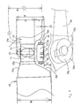
- Fig. 6 is an enlarged lateral view of the exhaust throttle valve 53 and Fig. 7 is an enlarged plan view of Fig. 6 .
- the exhaust throttle valve 53 is attached to the external lateral surface of the rear exhaust pipe 47 so as to be put between the catalyst chamber 15 and the exhaust chamber 16 from front and from back.
- a pulley 70 is provided in the exhaust throttle valve 53 and is turnably driven by cables 71 to turn a throttle valve 72 provided inside the rear exhaust pipe 47, thereby adjusting an amount of exhaust gas.
- the cables 71 extend upward from the upper portion of the exhaust throttle valve 53 and are turned by an actuator not shown on the basis of the rotation number of the engine.
- the throttle valve 72 is provided integrally with the pulley 70 for rotation and the passage-sectional area of the rear exhaust pipe 47 is variably controlled to adjust an amount of exhaust flow.
- the throttling by the throttle valve 72 is controlled by a controller (not shown) on the basis of the rotation number of the engine.
- the throttle valve 72 is closed to reduce exhaust noise.
- the throttle valve 72 is opened to enable high power.
- known control methods, types, structures and the like can be applicable.
- a drive portion of the exhaust throttle valve 53 is a portion thereof exposed to the external lateral surface of the rear exhaust pipe 47.
- a back-and-forth length L1 of this drive portion is approximately equal to a back-and-forth length L2 of the rear exhaust pipe 47.
- the back-and-forth length L2 of the rear exhaust pipe 47 includes the respective lengths of a connection flange 15e provided on a rear wall 15c of the catalyst chamber 15 and a connection flange 16e provided on a front wall 16a of the exhaust chamber 16. In this way, the catalyst chamber 15 and exhaust chamber 16 which are large-size components can be compactly disposed with respect to the exhaust throttle valve 53 from front and from back.
- the exhaust throttle valve 53 is provided with a case 73 which projects externally sideward of the rear exhaust pipe 47 and is covered, from the external side, with a lid 74 secured thereto with bolts 75.
- a rotary shaft 76 turned integrally with the pulley 70 passes through the rear exhaust pipe 47, projects from the right lateral surface thereof and is secured thereto with an attachment 77.
- the exhaust throttle valve 53 is integrally attached to the rear exhaust pipe 47.
- the throttle valve 72 is integrally attached to the rotary shaft 76 in the rear exhaust pipe 47.
- the throttle valve 72 may be of a known type such as a butterfly valve or the like.
- each of the respective vehicle-widthwise widths W1 and W2 of the catalyst chamber 15 and exhaust chamber 16 is greater than the pipe diameter of the rear exhaust pipe 47.
- a drive portion which is a portion of the exhaust throttle valve 53 and includes the case 73 and the lid 74 is exposed to the outside of the rear exhaust pipe 47 and externally protrudes by a dimension d.
- the external surface 15b of the catalyst chamber 15 protrudes externally laterally from the exposure portion of the external throttle valve 53 by d1 and the external surface 16b of the exhaust chamber 16 recedes from the exposure portion of the external throttle valve 53 by d2.
- d2 is very small.
- the rear wall 15c of the catalyst chamber 15 is reduced in diameter toward the inside of the vehicle body to form a slant surface and in particular the external surface 15d is largely slanted.
- the front wall 16a of the catalyst chamber 15 externally laterally projects nearly equally to the case 73.
- the external surface 15d, the rear exhaust pipe 47 and the front wall 16a define a recessed space 78 receding into the inward of the vehicle body. The exposure portion such as the case 73 and the like is received inside the recessed space 78.
- the exposure portion such as the case 73 and the like is guarded by the external surface 15d from the front and by the front wall 16a from the rear so as to be protected against disturbance due to scattered stones or the like.
- a vehicle body attachment portion of the side stand 39 is disposed externally of the exhaust throttle valve 53 by way of example.
- a boss portion 39a which is the vehicle body attachment portion provided at one end of the side stand, is turnably attached to a support plate 39c with a bolt 39b. While being stored, the side stand 39 is turned to be approximately horizontal so that its rear end side is moved rearward.
- the support plate 39c is attached to the lower portion of the pivot plate 7 ( Fig. 1 ). In this way, the exhaust throttle valve 53 can be protected against disturbance due to scattered stones by the vehicle body attachment portion of the side stand 39.
- the vehicle body attachment portion of the side stand 39 may be removed forward and the side stand may be approximately parallel to the rear exhaust pipe 47 during storage so as to cover the exhaust throttle valve 53 from the outside.
- the side stand 39 stored during running can effectively be used to protect the exhaust throttle valve 53 against disturbance due to scattered stones or the like.
- Fig. 8 is a cross-sectional view of the exhaust chamber 16 and muffler 17, taken along line 8-8 of Fig. 5 .
- the exhaust chamber 16 and the front portion 60 of the muffler 17 are arranged at respective different levels so that the front portion 60 is located higher than the exhaust chamber 16.
- the front portion 60 is formed in an appropriate inverted triangle in cross-section.
- the right lateral surface 60c is formed as a slant surface so that its lower portion faces the inside of the vehicle body, thereby providing a bank angle ⁇ .
- Symbol H denotes a horizontal line coincident with the bottom surface of the exhaust chamber 16.
- the right lateral surface 60c is formed as the downward slant surface, scattered stones 79 or the like are bounced externally downward from the right lateral surface 60c so that they can be prevented from moving toward the exhaust chamber 16 and further toward the exhaust throttle valve 53.
- the right lateral surface 60c of the exhaust chamber 16 is slanted such that the rear side thereof externally opens also as viewed from above.
- stones 79 or the like scattered from the front are bounced from the right lateral surface 60c toward the oblique outside and toward the rear, also thereby being prevented from moving toward the exhaust throttle valve 53.
- the exhaust throttle valve 53 is attached to the rear exhaust pipe 47 at a position between the catalyst chamber 15 which is the connecting portion disposed near the lower portion of the engine and the exhaust chamber 16 disposed downstream of the catalyst chamber 15 so as to connect therewith through the rear exhaust pipe 47.
- the exhaust throttle valve 53 is surrounded by the catalyst chamber 15 and the exhaust chamber 16 to thereby protect the exhaust throttle valve 53 from disturbance due to stones or the like scattered by the front wheel 1 or the like.
- the lateral width W1 of the catalyst chamber 15 disposed forward of the exhaust throttle valve 53 is made greater than the lateral width W of the 53.
- the catalyst chamber 15 can prevent the exhaust throttle valve 53 from disturbance due to scattered stones.
- the exhaust throttle valve 53 can be protected from disturbance due to stones or the like scattered from the front of the vehicle during running.
- the exhaust throttle valve 53 can further effectively be protected from disturbance due to stones or the like scattered from the front wheel side.
- the lateral width W2 of the exhaust chamber 16 disposed rearward of the exhaust throttle valve 53 is made greater than the lateral width W of the rear exhaust pipe 47 including the exhaust throttle valve 53. Therefore, the exhaust throttle valve 53 can effectively be prevented from disturbance due to scattered stones bounced from the rear portion of the vehicle.
- the right lateral surface 60c which is an external lateral surface of the muffler 17 slants to externally open toward the rearward. Therefore, if the disturbance due to stones scattered from the front of the vehicle hits the right lateral surface 60c of the muffler 17, it can be bounced obliquely externally and rearward by the right lateral surface 60c which is the externally opening slant surface. This can prevent the exhaust throttle valve from being hit by the disturbance due to stones scattered from the front of the vehicle and bounced from the muffler.
- the catalyst chamber 15 and exhaust chamber 16 which are components larger than the exhaust throttle valve 53 are disposed forward of and rearward of, respectively, the exhaust throttle valve 53 so as to put it therebetween.
- the back-and-forth length L2 of the rear exhaust pipe 47 which is an interval between the catalyst chamber 15 and the exhaust chamber 16 is made approximately equal to the back-and-forth length L1 of the exhaust throttle valve 53. Therefore, the back-and-forth interval of the exhaust throttle valve 53 can be reduced by the catalyst chamber 15 and by the exhaust chamber 16. This can prevent the exhaust throttle valve 53 from disturbance due to being hit by scattered stones or the like.
- the exhaust throttle valve 53 is disposed to recede inside of the vehicle body from the external lateral portion of the catalyst 15, it can further easily be protected from the disturbance due to scattered stones or the like. Further, if the side stand 39 during storage or the boss 39a and attachment plate 39c which are attachment portions of the side stand are designed to overlap the outside of the exhaust throttle valve 53, the side stand 39 during storage or the attachment portions 39a, 39c cover the exhaust throttle valve 53 from laterally outside to protect it from disturbance due to scattered stones or the like.
- the present invention is not limited to the embodiments described above and can be modified or applied in various ways within the principles of the invention.
- the catalyst chamber may be replaced by the exhaust chamber which is a mere expansion chamber.
Landscapes
- Engineering & Computer Science (AREA)
- Chemical & Material Sciences (AREA)
- Combustion & Propulsion (AREA)
- Mechanical Engineering (AREA)
- General Engineering & Computer Science (AREA)
- Exhaust Silencers (AREA)
- Control Of Throttle Valves Provided In The Intake System Or In The Exhaust System (AREA)
Abstract
Description
- The present invention relates to an exhaust device for a motorcycle, and in particular to an exhaust throttle valve arrangement structure advantageous to disturbance due to scattered stones or the like.
- It is known that an exhaust throttle valve is provided in the exhaust system of an engine to adjust an amount of exhaust flow according to operating conditions, thereby intending to reduce exhaust noise and to provide high power.
- Examples of provision of such an exhaust throttle valve include one in which the exhaust throttle valve is provided at a collecting portion disposed forward of an engine (see Japanese Utility Model Publication No.
Hei 4-20983 Hei 4-292534 - Since the exhaust throttle valve is provided at the exhaust system, it is sometimes disposed close to a front wheel or a rear wheel or on the vehicle body lower portion close to the ground surface. If the exhaust throttle valve is located at any one of such position, it tends to undergo disturbance due to scattered stones or the like.
- For Japanese Utility Model Publication No.
Hei 4-20983 - For Japanese Patent Laid-open No.
Hei 4-292534 - In addition, it is desired that the structure for protecting such a component from the disturbance due to scattered stones or the like be realized as simply as possible.
- According to a first aspect of the invention, there is provided an exhaust device for a motorcycle comprising: a plurality of exhaust pipes connected to associated exhaust ports of a multi-cylinder engine; a collecting portion collecting the exhaust pipes at a position close to the lower portion of the engine; a rear exhaust pipe connected to the downstream side of the collecting portion; an exhaust chamber connected to the downstream side of the rear exhaust pipe; an exhaust outlet portion provided on the downstream side of the exhaust chamber; a muffler connected to the downstream side of the exhaust outlet portion; and an exhaust throttle valve disposed inside a passage of the rear exhaust pipe to change an amount of exhaust flow.
- The exhaust throttle valve is attached to the rear exhaust pipe at a position between the collecting portion disposed near the lower portion of the engine and the exhaust chamber disposed downstream of the collecting portion and connected thereto via the rear exhaust pipe. Therefore, the exhaust throttle valve is surrounded by the collecting portion and the exhaust chamber so that it can be protected from disturbance due to stones or the like scattered by the front wheel or the like.
- Preferably, a lateral width of the collecting portion is greater than a lateral width of the rear exhaust pipe including the exhaust throttle valve, as viewed from above.
- Since the lateral width of the collecting portion disposed forward of the exhaust throttle valve is made greater than the lateral width of the rear exhaust pipe including the exhaust throttle valve, the external side of the collecting portion is made to protrude externally from the rear exhaust pipe. Therefore, the collecting portion can protect the exhaust throttle valve against disturbance due to scattered stones or the like. In particular, the exhaust throttle valve can be protected from disturbance due to stones scattered from the front of the vehicle during running.
- It is further preferred for the lateral width of the exhaust chamber to be greater than that of the rear exhaust pipe including the exhaust throttle valve, as viewed from above.
- Then, the exhaust throttle valve can be prevented from being hit by disturbance due to scattered stones bounced from the rear portion of the vehicle.
- Preferably, the muffler is formed such that a vehicle-widthwise outside thereof is slanted to externally open toward the rearward.
- Thus, if stones scattered from the front of the vehicle hits the muffler, they can be bounced obliquely externally and rearward from the externally opening slant surface. Thus, the exhaust throttle valve can be prevented from being hit by stones scattered from the front of the vehicle and bounced from the muffler.
- In a preferred form, a back-and-forth length of a portion, of the exhaust throttle valve, disposed outside of the rear exhaust pipe is approximately equal to a back-and-forth length of the rear exhaust pipe.
- The collecting portion and exhaust chamber which are components larger than the exhaust throttle valve are disposed forward of and rearward of, respectively, the exhaust throttle valve with respect to the vehicle. In addition, the back-and-forth length of the rear exhaust pipe which corresponds to the interval between the collecting portion and the exhaust chamber is made approximately equal to the back-and-forth length of the exhaust throttle valve. Therefore, the back-and-forth interval of the exhaust throttle valve can be reduced by the collecting portion and by the exhaust chamber. This can prevent the exhaust throttle valve from being hit by disturbance due to scattered stones or the like.
- Preferably, the exhaust throttle valve is disposed to recede from an external lateral portion of the collecting portion toward the inside of a vehicle body.
- Then, the exhaust throttle valve can easily be protected from disturbance due to scattered stones or the like.
- Preferably, a side stand during storage or an attachment portion overlaps the outside of the exhaust throttle valve as viewed from the side.
- The side stand during storage or the attachment portion is made to overlap the outside of the exhaust throttle valve. Therefore, the side stand during storage or the attachment portion covers the exhaust throttle valve from the externally lateral side thereof to protect it from disturbance due to scattered stones or the like.
- A preferred ,embodiment of the invention will now be described by way of example only and with reference to the accompanying drawings, in which:
-
Fig. 1 is a lateral view of a motorcycle according to an embodiment; -
Fig. 2 is a plan view mainly illustrating an exhaust system; -
Fig. 3 illustrates an engine from the rear; -
Fig. 4 is a lateral view of the exhaust system; -
Fig. 5 is a plan view of the exhaust system; -
Fig. 6 is an enlarged lateral view illustrating a portion mainly including a muffler; -
Fig. 7 is an enlarged plan view ofFig. 6 ; and -
Fig. 8 is a cross-sectional view taken along line 8-8 ofFig. 5 . -
Fig. 1 is a lateral view of a motorcycle according to the embodiment. The motorcycle is such that a V-type water-cooled 4-cylinder engine 3 is disposed between a front wheel 1 and arear wheel 2 and supported by abody frame 4. - A
hanger 5 is attached to the intermediate portion of thebody frame 4 so as to support the front portion of theengine 3. Ahead pipe 6 is attached to the front end of thebody frame 4 and apivot plate 7 is supported by the rear portion of thebody frame 4. Afuel tank 8 is supported on the intermediate portion of thebody frame 4 and anair intake box 9 is received inside the front portion of thefuel tank 8. - The
air intake box 9 sucks air from front and supplies the air tofront cylinders 10 andrear cylinders 11 located below theair intake box 9. Theair intake box 9 is disposed above the valley portion between thefront cylinders 10 and therear cylinders 11. - Front
side exhaust pipes 12 extend forward from the respectivefront cylinders 10 and rearside exhaust pipes 13 extend rearward from the respectiverear cylinders 11. The frontside exhaust pipes 12 extend downward along the front surface of acrankcase 14 of theengine 3 and connect, from front, with acatalyst chamber 15 located below thecrankcase 14, via a collecting pipe. Also the rearside exhaust pipes 13 connect, from front, with thecatalyst chamber 15 via another collecting pipe as described later. - The
catalyst chamber 15 connects with anexhaust chamber 16, an expansion chamber, disposed rearward thereof. Theexhaust chamber 16 is disposed in a space defined between the lower portion of thecrankcase 14 and therear wheel 2 and connects with amuffler 17 extending on the right side of therear wheel 2 with respect to the vehicle body. Theexhaust chamber 16 is supported by the lower end of thepivot plate 7 at two, front and rear,attachment portions - The
muffler 17 is disposed to cross arear swing arm 20 as viewed from the side. Therear swing arm 20 has a front end portion which is supported by thepivot plate 7 with thepivot shaft 21 so as to be swingable up and down and is suspended by arear cushion 22 provided between the upper end of thepivot plate 7 and therear swing arm 20. - A
suspension link 23 is provided between the lower end of thepivot plate 7 and the intermediate portion of theattachment portion 18. Theexhaust chamber 16 is disposed below thesuspension link 23 so as to avoid thesuspension link 23. The front end of themuffler 17 is located at a position approximately equal to that of thesuspension link 23 higher, by one step, than theexhaust chamber 16. - The
rear wheel 2 is of a shaft drive type and is driven by theengine 3. Aseat 24 is supported on aseat rail 25 so as to be located above therear swing arm 20 and rearward of thefuel tank 8. Theseat rail 25 is supported by thepivot plate 7 at its front end. - A
radiator 26 is disposed forward of thefront cylinders 10 and rearward of the front wheel 1 and has an upper portion suspended and supported by the front portion, of thebody frame 4, close to thehead pipe 6. Theradiator 26 is supported with the head bent forward in which the upper portion is slanted forward. A gap is defined between theradiator 26, and thefront cylinders 10 and thecrankcase 14. The frontside exhaust pipes 12 are vertically passed through the gap. - The lower end of the
radiator 26 is supported by thecrankcase 14 via astay 27 extending forward from the front lower portion of thecrankcase 14. A feed-water hose 28 extends rearward from a lateral tank of theradiator 26 and connects with a feed-water pump 29 provided at the lateral portion of thecrankcase 14. - Water is fed from the feed-
water pump 29 via ajoint hose 30 to a water jacket feed-water portion provided in the valley between thefront cylinders 10 and therear cylinders 11. Then the water is fed from the water jacket feed-water portion to the respective water jackets of thefront cylinders 10 and the rear'cylinders 11. The water circulates the water jackets to cool the cylinders for heat exchange and the water thus heated is fed to areturn hose 32 via athermostat 31 located above the feed-water portion in the valley between thefront cylinders 10 and therear cylinders 11. - The
return hose 32 extends downward to the lateral surface of thecrankcase 14, then extending forward, and connects with the lateral tank of theradiator 26. In this way, the heated water is returned by thereturn hose 32 to theradiator 26. -
Fig. 2 is a plan view mainly illustrating an exhaust system. Thecatalyst chamber 15 is disposed to be leftward offset with respect to the body centre C and theexhaust chamber 16 is located approximately on the body centre C. A laterally-facingoutlet pipe 40 is provided at a right-hand rear end portion of theexhaust chamber 16 so as to project rightward outwardly and joined to the left-lateral surface of the front end of themuffler 17. Themuffler 17 is disposed to extend in the back and forth direction and slanted so that its rear side opens outwardly toward the right side of the vehicle body. - The two front
side exhaust pipes 12 are provided in total for the respective left and right cylinders. The frontside exhaust pipes 12 extend downward and toward the right side of the vehicle body, bending at their lower portions and crossing the vehicle-widthwise direction from the right side of the vehicle body to the left side, collectively join to the collectingpipe 41 and connect with thecatalyst chamber 15. Also the two rearside exhaust pipes 13 are provided in total for the respective left and right cylinders, extending downward, and collectively join to the singlerear collecting pipe 42. Therear collecting pipe 42 extends downward of and rightward of thecrankcase 14 not to interfere therewith, extending from the rear to the front, turning leftward of the vehicle body at a position close to the lower portions of the frontside exhaust pipes 12, and connects, from the front, with thecatalyst chamber 15 inward of thefront collecting pipe 41. Thecrankcase 14 partially overlaps thecatalyst chamber 15 andrear collecting pipe 42 as viewed from above. -
Reference numeral 33 is a pillion step holder, which is provided right and left of the vehicle body. The rightpillion step holder 33 supports themuffler 17 at its lower end portion.Reference numeral 34 denotes a pillion step and 35 denotes a step holder supported by theseat rail 25.Reference numeral 36 denotes a step, 37 denotes a brake pedal, 38 denotes a change pedal and 39 denotes a side stand. These components are supported by the lower portion of thepivot plate 7. -
Fig. 3 illustrates theengine 3 as viewed from the rearward. Anoil pan 43 is attached to the bottom portion of thecrankcase 14. Theoil pan 43 is formed to have such a curved surface that itsbottom portion 44 lowers toward the vehicle-widthwise centre. The central portion of thebottom portion 44 protrudes lengthwise downward to form areservoir chamber 45. A portion, of thebottom portion 44, excluding thereservoir chamber 45 functions as an introduction portion for guiding oil into thereservoir chamber 45 and does not function so much to store oil thereon, so that it can be thinned. Thus, theoil pan 43 is formed thin as a whole and in an almost-T shape as viewed from the rearward (or as viewed from the front). - The
reservoir chamber 45 is formed like a recessed groove narrow, relatively deep and elongated in the back and forth direction (seeFig. 5 ). An arrangement space for therear collecting pipe 42 and thecatalyst chamber 15 is sufficiently widely ensured right and left of thereservoir chamber 45. The upper portion of thereservoir chamber 45 merges with thebottom portion 44 protruding right and left so that oil can efficiently be' collected into thereservoir chamber 45. Astrainer 46 is received in theoil pan 43 and its suction port is disposed close to the bottom portion ofreservoir chamber 45. An oil pump not shown in thecrankcase 14 sucks upward the oil collected in thedeep reservoir chamber 45 and feeds it to the journal portions of the cylinders and other portions needing lubrication. Since the suction port of thestrainer 46 is disposed near the bottom portion of the narrow, relativelydeep reservoir chamber 45, a necessary amount of oil can be ensured around the suction port so that the oil can stably be sucked even when the vehicle body is tilted. Therear collecting pipe 42 and thecatalyst chamber 15 are disposed on the right and left, respectively, of thereservoir chamber 45 so as to be close thereto lengthwise in the back and forth direction. - The
reservoir chamber 45 is provided at a position slightly offset from the body centre C to the right so that a relatively large space is formed below thebottom portion 44 on the left side of thereservoir chamber 45. Thecatalyst chamber 15 is disposed in the space. Afront collecting pipe 41 and arear collecting pipe 42 are joined to the front surface of thecatalyst chamber 15 and arear exhaust pipe 47 is joined to the rear surface of thecatalyst chamber 15. Thecatalyst chamber 15 is a relatively-flat cylindrical body formed in a horizontally-long oval in cross-section and internally receives a known exhaust purification catalyst with honeycomb structure or the like. - A
guard plate 48 is disposed on the under side of thecatalyst chamber 15. Theguard plate 48 includes left and rightbent lateral portions catalyst chamber 15 from left and from right. The rightlateral portion 48b is formed like a curved surface along thecatalyst chamber 15 to enter into between thecatalyst chamber 15 and thereservoir chamber 15. Theguard plate 48 is disposed to slant along theleft bank line 48c. - A space slightly smaller than the left-hand space is provided also on the right side of the
reservoir chamber 45 and below thebottom portion 44. The singlerear collecting pipe 42 is passed through this space in the,back and forth direction. Also aguide plate 49 is provided rightward and obliquely downward of therear collecting pipe 42. Theguide plate 49 is also disposed to slant along a right-hand bank line 49a. The left andright bank lines - The exhaust system is hereinafter described in further detail.
Fig. 4 is a lateral view of the exhaust system. Cylinder heads 50 of thefront cylinders 10 are provided right and left. The two frontside exhaust pipes 12 connected to the respective exhaust ports of the cylinder heads 50 extend downward in front of thecrankcase 14, bending at their lower ends, and connect with the approximately Y-shapedfront pipe 41. The rear side of thefront collecting pipe 41 is formed as a single one, which connects with thecatalyst chamber 15. An O2 sensor 51 is provided right before the joint portion with thecatalyst chamber 15 so as to project upward from the upper surface thereof. - Incidentally, another O2 sensor 51 is provided, so as to project upward, at a position close to the joint portion between the
catalyst chamber 15 and therear collecting pipe 42 which cannot be seen in the figure because of being superposed by thefront collecting pipe 41. The O2 sensor 51 measures oxygen concentration in exhaust gas before purification. - Cylinder heads 52 of the
rear cylinders 11 are provided right and left. The two rearside exhaust pipes 13 connected to the respective exhaust ports of the cylinder heads 52 extend obliquely downwardly and rearward, bending at a position above theexhaust chamber 16, extending approximately vertically downwardly, and connect withbranch portions rear pipe 42 which is also approximately Y-shaped. - A drive portion of an
exhaust throttle valve 53 is provided, so as to be exposed, at the lateral surface of therear exhaust pipe 47 which connects the rear portion of thecatalyst chamber 15 with the front portion of theexhaust chamber 16. Theexhaust throttle valve 53 is designed to control an amount of exhaust gas by changing the passage-sectional area of therear exhaust pipe 47 according to the travelling conditions. - The respective bottom surfaces of the
catalyst chamber 15 and theexhaust chamber 16 are located on respective horizontal lines H having approximately the same height to ensure a sufficient minimum ground clearance. However, the vertical width (thickness) of theexhaust chamber 16 is greater than that of thecatalyst chamber 15. Theexhaust chamber 16 ensures the necessary vertical width by extending the upper surface upward. This is enabled by disposing theexhaust chamber 16 in the space put between the lower portion of theengine 3 and the rear wheel from front and from rear and by using the space formed below the rear swing arm 20 (Fig. 1 ) located above theexhaust chamber 16. - The
exhaust chamber 16 is formed with a raisedportion 54 at the intermediate portion of the upper surface thereof and recessedportions portion 54. The recessedportion 55 is adapted to avoid the lower end portion of thepivot plate 7 and similarly the recessedportion 56 is adapted to avoid thesuspension link 23. - The
attachment portion 18 is provided at the end of astay 18a upwardly projecting from the front end of theexhaust chamber 16. Similarly, theattachment portion 19 is provided at the end of astay 19a upwardly projecting from the raisedportion 54 of theexhaust chamber 16. Thus, theexhaust chamber 16 is rubber-mounted to thepivot plate 7. Theoutlet pipe 40 extends rearward from the rear end of theexhaust chamber 16 while being reduced in diameter. To form theoutlet pipe 40, a recessedportion 57 is formed by reducing the diameter of the rear end portion of theexhaust chamber 16. - The
muffler 17 includes afront portion 60 formed in an approximate triangle and amain body portion 61, which are lined and welded integrally with each other. Theoutlet pipe 40 is joined to the lateral surface of thefront portion 60 close to an acute front end portion 60a thereof. An upper surface 60b of thefront portion 60 is formed as a taper surface which extends forwardly and obliquely downwardly. The front end portion 60a of thefront portion 60 partially overlaps the rear end portion of theexhaust chamber 16 at a portion of theoutlet pipe 40. - The
main body portion 61 is formed like a tube having an approximately uniform diameter. A rear end portion of themain body portion 61 is closed by anend cap 62 whose upper portion projects rearward from the other portion.Reference numeral 58 denotes a stay attached to the pillion step holder 33 (Fig. 1 ). - -
Fig. 5 is a plan view of the exhaust system. The frontside exhaust pipes 12 have respective lower portions which bend vehicle-widthwise at a position forward of therear collecting pipe 42 and overlap one on another. The rearside exhaust pipes 13 overlap one on another along the right-hand surface of theexhaust chamber 16, extending rearward to the vicinity of theoutlet pipe 40, then bending downward, and connect with thebranch portions rear collecting pipe 42. - The
outlet pipe 40 projects rightward from the internal surface of the rear end portion of theexhaust chamber 16 and is connected to afront pipe 63 with aband 64. Thefront pipe 63 projects leftward from the internal surface of the front end portion of thefront portion 60. In addition, thefront pipe 63 is an inlet pipe of themuffler 17. - The joint portion between the
outlet pipe 40 and thefront pipe 63 is located slightly rearward from the front end portion 60a of thefront portion 60 of themuffler 17 to form a space there. Aband 65 used to secure a joint portion between the rearside exhaust pipe 13 and therear collecting pipe 42 partially faces this space. Anexternal surface 60c of thefront portion 60 of themuffler 17 is formed as a taper surface which slants so that its front side faces the central side of the vehicle body. - An
external surface 15d of arear wall 15c of thecatalyst chamber 15 is formed as a taper surface whose rear side enters inside the vehicle body and is reduced in diameter to have approximately the same diameter as that of therear exhaust pipe 47. A recessed space surrounded by therear wall 15c and thefront wall 16a of theexhaust chamber 16 is formed externally of therear exhaust pipe 47. Theexhaust throttle valve 53 is received in this recessed space to be protected from scattered stones or the like. ' - A description is next made of the arrangement of the
exhaust throttle valve 53.Fig. 6 is an enlarged lateral view of theexhaust throttle valve 53 andFig. 7 is an enlarged plan view ofFig. 6 . Referring toFig. 6 , theexhaust throttle valve 53 is attached to the external lateral surface of therear exhaust pipe 47 so as to be put between thecatalyst chamber 15 and theexhaust chamber 16 from front and from back. Apulley 70 is provided in theexhaust throttle valve 53 and is turnably driven bycables 71 to turn athrottle valve 72 provided inside therear exhaust pipe 47, thereby adjusting an amount of exhaust gas. Thecables 71 extend upward from the upper portion of theexhaust throttle valve 53 and are turned by an actuator not shown on the basis of the rotation number of the engine. - The
throttle valve 72 is provided integrally with thepulley 70 for rotation and the passage-sectional area of therear exhaust pipe 47 is variably controlled to adjust an amount of exhaust flow. The throttling by thethrottle valve 72 is controlled by a controller (not shown) on the basis of the rotation number of the engine. During low-speed rotation, thethrottle valve 72 is closed to reduce exhaust noise. During high-speed rotation, thethrottle valve 72 is opened to enable high power. However, known control methods, types, structures and the like can be applicable. - A drive portion of the
exhaust throttle valve 53 is a portion thereof exposed to the external lateral surface of therear exhaust pipe 47. A back-and-forth length L1 of this drive portion is approximately equal to a back-and-forth length L2 of therear exhaust pipe 47. Incidentally, the back-and-forth length L2 of therear exhaust pipe 47 includes the respective lengths of aconnection flange 15e provided on arear wall 15c of thecatalyst chamber 15 and aconnection flange 16e provided on afront wall 16a of theexhaust chamber 16. In this way, thecatalyst chamber 15 andexhaust chamber 16 which are large-size components can be compactly disposed with respect to theexhaust throttle valve 53 from front and from back. - Referring to
Fig. 7 , theexhaust throttle valve 53 is provided with acase 73 which projects externally sideward of therear exhaust pipe 47 and is covered, from the external side, with alid 74 secured thereto withbolts 75. Arotary shaft 76 turned integrally with thepulley 70 passes through therear exhaust pipe 47, projects from the right lateral surface thereof and is secured thereto with anattachment 77. In this way, theexhaust throttle valve 53 is integrally attached to therear exhaust pipe 47. Thethrottle valve 72 is integrally attached to therotary shaft 76 in therear exhaust pipe 47. Thethrottle valve 72 may be of a known type such as a butterfly valve or the like. - If a pipe diameter of the
rear exhaust pipe 47 is D and a vehicle-widthwise width including the exhaust throttle valve is W, each of the respective vehicle-widthwise widths W1 and W2 of thecatalyst chamber 15 andexhaust chamber 16 is greater than the pipe diameter of therear exhaust pipe 47. - A drive portion which is a portion of the
exhaust throttle valve 53 and includes thecase 73 and thelid 74 is exposed to the outside of therear exhaust pipe 47 and externally protrudes by a dimension d. Theexternal surface 15b of thecatalyst chamber 15 protrudes externally laterally from the exposure portion of theexternal throttle valve 53 by d1 and theexternal surface 16b of theexhaust chamber 16 recedes from the exposure portion of theexternal throttle valve 53 by d2. However, d2 is very small. - The
rear wall 15c of thecatalyst chamber 15 is reduced in diameter toward the inside of the vehicle body to form a slant surface and in particular theexternal surface 15d is largely slanted. Also thefront wall 16a of thecatalyst chamber 15 externally laterally projects nearly equally to thecase 73. Thus, theexternal surface 15d, therear exhaust pipe 47 and thefront wall 16a define a recessedspace 78 receding into the inward of the vehicle body. The exposure portion such as thecase 73 and the like is received inside the recessedspace 78. - In this way, the exposure portion such as the
case 73 and the like is guarded by theexternal surface 15d from the front and by thefront wall 16a from the rear so as to be protected against disturbance due to scattered stones or the like. - Incidentally, as indicated with imaginary lines in
Fig. 7 , also the exposure portion can be protected against disturbance due to scattered stones or the like by using theside stand 39. In the figure, a vehicle body attachment portion of the side stand 39 is disposed externally of theexhaust throttle valve 53 by way of example. Aboss portion 39a, which is the vehicle body attachment portion provided at one end of the side stand, is turnably attached to asupport plate 39c with abolt 39b. While being stored, the side stand 39 is turned to be approximately horizontal so that its rear end side is moved rearward. Thesupport plate 39c is attached to the lower portion of the pivot plate 7 (Fig. 1 ). In this way, theexhaust throttle valve 53 can be protected against disturbance due to scattered stones by the vehicle body attachment portion of theside stand 39. - The vehicle body attachment portion of the side stand 39 may be removed forward and the side stand may be approximately parallel to the
rear exhaust pipe 47 during storage so as to cover theexhaust throttle valve 53 from the outside. In this case, the side stand 39 stored during running can effectively be used to protect theexhaust throttle valve 53 against disturbance due to scattered stones or the like. -
Fig. 8 is a cross-sectional view of theexhaust chamber 16 andmuffler 17, taken along line 8-8 ofFig. 5 . Referring toFig. 8 , theexhaust chamber 16 and thefront portion 60 of themuffler 17 are arranged at respective different levels so that thefront portion 60 is located higher than theexhaust chamber 16. In addition, thefront portion 60 is formed in an appropriate inverted triangle in cross-section. The rightlateral surface 60c is formed as a slant surface so that its lower portion faces the inside of the vehicle body, thereby providing a bank angle θ. Symbol H denotes a horizontal line coincident with the bottom surface of theexhaust chamber 16. - In this way, since the right
lateral surface 60c is formed as the downward slant surface,scattered stones 79 or the like are bounced externally downward from the rightlateral surface 60c so that they can be prevented from moving toward theexhaust chamber 16 and further toward theexhaust throttle valve 53. - Similarly, as shown in
Fig. 5 , the rightlateral surface 60c of theexhaust chamber 16 is slanted such that the rear side thereof externally opens also as viewed from above. Thus,stones 79 or the like scattered from the front are bounced from the rightlateral surface 60c toward the oblique outside and toward the rear, also thereby being prevented from moving toward theexhaust throttle valve 53. - A description is next made of the operation of the present embodiment. As shown in
Figs. 6 and7 , theexhaust throttle valve 53 is attached to therear exhaust pipe 47 at a position between thecatalyst chamber 15 which is the connecting portion disposed near the lower portion of the engine and theexhaust chamber 16 disposed downstream of thecatalyst chamber 15 so as to connect therewith through therear exhaust pipe 47. Thus, theexhaust throttle valve 53 is surrounded by thecatalyst chamber 15 and theexhaust chamber 16 to thereby protect theexhaust throttle valve 53 from disturbance due to stones or the like scattered by the front wheel 1 or the like. ' - In this case, the lateral width W1 of the
catalyst chamber 15 disposed forward of theexhaust throttle valve 53 is made greater than the lateral width W of the 53. Thus, thecatalyst chamber 15 can prevent theexhaust throttle valve 53 from disturbance due to scattered stones. In particular, theexhaust throttle valve 53 can be protected from disturbance due to stones or the like scattered from the front of the vehicle during running. In addition, since the left lateral surface of thecatalyst chamber 15 is externally protruded from therear exhaust pipe 47 and from theexhaust throttle valve 53, theexhaust throttle valve 53 can further effectively be protected from disturbance due to stones or the like scattered from the front wheel side. - Similarly, the lateral width W2 of the
exhaust chamber 16 disposed rearward of theexhaust throttle valve 53 is made greater than the lateral width W of therear exhaust pipe 47 including theexhaust throttle valve 53. Therefore, theexhaust throttle valve 53 can effectively be prevented from disturbance due to scattered stones bounced from the rear portion of the vehicle. - The right
lateral surface 60c which is an external lateral surface of themuffler 17 slants to externally open toward the rearward. Therefore, if the disturbance due to stones scattered from the front of the vehicle hits the rightlateral surface 60c of themuffler 17, it can be bounced obliquely externally and rearward by the rightlateral surface 60c which is the externally opening slant surface. This can prevent the exhaust throttle valve from being hit by the disturbance due to stones scattered from the front of the vehicle and bounced from the muffler. - Further, the
catalyst chamber 15 andexhaust chamber 16 which are components larger than theexhaust throttle valve 53 are disposed forward of and rearward of, respectively, theexhaust throttle valve 53 so as to put it therebetween. The back-and-forth length L2 of therear exhaust pipe 47 which is an interval between thecatalyst chamber 15 and theexhaust chamber 16 is made approximately equal to the back-and-forth length L1 of theexhaust throttle valve 53. Therefore, the back-and-forth interval of theexhaust throttle valve 53 can be reduced by thecatalyst chamber 15 and by theexhaust chamber 16. This can prevent theexhaust throttle valve 53 from disturbance due to being hit by scattered stones or the like. - Since the
exhaust throttle valve 53 is disposed to recede inside of the vehicle body from the external lateral portion of thecatalyst 15, it can further easily be protected from the disturbance due to scattered stones or the like. Further, if the side stand 39 during storage or theboss 39a andattachment plate 39c which are attachment portions of the side stand are designed to overlap the outside of theexhaust throttle valve 53, the side stand 39 during storage or theattachment portions exhaust throttle valve 53 from laterally outside to protect it from disturbance due to scattered stones or the like. - Incidentally, the present invention is not limited to the embodiments described above and can be modified or applied in various ways within the principles of the invention. For example, as the collecting portion disposed below the engine, the catalyst chamber may be replaced by the exhaust chamber which is a mere expansion chamber.
Claims (7)
- An exhaust device for a motorcycle comprising:a plurality of exhaust pipes connected to associated exhaust ports of a multi-cylinder engine;a collecting portion collecting the exhaust pipes at a position close to a lower portion of the engine;a rear exhaust pipe connected to the downstream side of the collecting portion;an exhaust chamber connected to the downstream side of the rear exhaust pipe;an exhaust outlet portion provided on the downstream side of the exhaust chamber;a muffler connected to the downstream side of the exhaust outlet portion; andan exhaust throttle valve disposed inside a passage of the rear exhaust pipe to change an amount of exhaust flow.
- The exhaust device for a motorcycle according to claim 1, wherein a lateral width of the collecting portion is greater than a lateral width of the rear exhaust pipe including the exhaust throttle valve, as viewed from above.
- The exhaust device for a motorcycle according to claim 1 or 2, wherein the lateral width of the exhaust chamber is greater than that of the rear exhaust pipe including the exhaust throttle valve, as viewed from above.
- The exhaust device for a motorcycle according to claim 1, 2 or 3, wherein the muffler is formed such that a vehicle-widthwise outside thereof is slanted to externally open toward the rearward.
- The exhaust device for a motorcycle according to claim 1, wherein a back-and-forth length of a portion, of the exhaust throttle valve, disposed outside of the rear exhaust pipe is approximately equal to a back-and-forth length of the rear exhaust pipe.
- The exhaust device for a motorcycle according to claim 1, wherein the_exhaust throttle valve is disposed to recede from an external lateral portion of the collecting portion toward the inside of a vehicle body.
- The exhaust device for a motorcycle according to claim 6, wherein a side stand during storage or an attachment portion overlaps the outside of the exhaust throttle valve as viewed from the side.
Applications Claiming Priority (1)
| Application Number | Priority Date | Filing Date | Title |
|---|---|---|---|
| JP2007095486A JP5015646B2 (en) | 2007-03-30 | 2007-03-30 | Exhaust system for motorcycles |
Publications (2)
| Publication Number | Publication Date |
|---|---|
| EP1978217A1 true EP1978217A1 (en) | 2008-10-08 |
| EP1978217B1 EP1978217B1 (en) | 2010-08-25 |
Family
ID=39580414
Family Applications (1)
| Application Number | Title | Priority Date | Filing Date |
|---|---|---|---|
| EP08251041A Not-in-force EP1978217B1 (en) | 2007-03-30 | 2008-03-25 | Exhaust device for motorcycle |
Country Status (5)
| Country | Link |
|---|---|
| US (1) | US8109084B2 (en) |
| EP (1) | EP1978217B1 (en) |
| JP (1) | JP5015646B2 (en) |
| CA (1) | CA2626396C (en) |
| DE (1) | DE602008002271D1 (en) |
Families Citing this family (8)
| Publication number | Priority date | Publication date | Assignee | Title |
|---|---|---|---|---|
| JP2011196242A (en) | 2010-03-19 | 2011-10-06 | Kawasaki Heavy Ind Ltd | Exhaust chamber of motorcycle |
| JP5895577B2 (en) * | 2012-02-14 | 2016-03-30 | スズキ株式会社 | Engine exhaust control device |
| JP5969328B2 (en) * | 2012-09-04 | 2016-08-17 | 川崎重工業株式会社 | Motorcycle |
| EP3048286B1 (en) * | 2013-09-19 | 2018-06-27 | Honda Motor Co., Ltd. | Structure for attaching an exhaust gas sensor of an internal combustion engine |
| JP6120457B2 (en) * | 2015-09-16 | 2017-04-26 | 本田技研工業株式会社 | Exhaust device for internal combustion engine |
| WO2017079156A1 (en) * | 2015-11-02 | 2017-05-11 | Roush Enterprises, Inc. | Muffler with selected exhaust pathways |
| JP7067211B2 (en) * | 2018-04-03 | 2022-05-16 | スズキ株式会社 | Exhaust gas sensor layout structure |
| JP6691585B2 (en) * | 2018-08-24 | 2020-04-28 | 本田技研工業株式会社 | Exhaust control valve for saddle type vehicles |
Citations (6)
| Publication number | Priority date | Publication date | Assignee | Title |
|---|---|---|---|---|
| EP0270121A2 (en) * | 1986-12-03 | 1988-06-08 | Yamaha Motor Co., Ltd. | Motor vehicle |
| JPS63255515A (en) * | 1987-04-14 | 1988-10-21 | Honda Motor Co Ltd | exhaust pipe device |
| JPH0420983U (en) | 1990-06-11 | 1992-02-21 | ||
| JPH04292534A (en) | 1991-03-20 | 1992-10-16 | Honda Motor Co Ltd | Exhaust control device of internal combustion engine for vehicle |
| EP1464824A1 (en) * | 2003-03-31 | 2004-10-06 | HONDA MOTOR CO., Ltd. | Fuel injection system for engine in small-type vehicle |
| EP1568864A1 (en) * | 2004-02-27 | 2005-08-31 | Kawasaki Jukogyo Kabushiki Kaisha | Motorcycle exhaust system |
Family Cites Families (12)
| Publication number | Priority date | Publication date | Assignee | Title |
|---|---|---|---|---|
| JPS56135708A (en) * | 1980-03-26 | 1981-10-23 | Yamaha Motor Co Ltd | Exhaust gas purifier for motor bicycle |
| CA1316114C (en) * | 1988-02-05 | 1993-04-13 | Takashi Ichimura | Exhaust system for multi-cylinder internal combustion engines and method for controlling same |
| US5189266A (en) * | 1989-06-09 | 1993-02-23 | Nissan Motor Co., Ltd. | Vehicular exhaust resonance suppression system and sensing means therefore |
| JP2586164B2 (en) * | 1990-02-03 | 1997-02-26 | トヨタ自動車株式会社 | Exhaust system of internal combustion engine |
| JP3194556B2 (en) * | 1993-11-26 | 2001-07-30 | 本田技研工業株式会社 | Exhaust throttle valve structure |
| KR100369212B1 (en) * | 1999-07-07 | 2003-01-24 | 한국과학기술연구원 | Method and Apparatus for Controlling Exhaust Noise in Internal Combustion Engine and/or Noise in Duct of Air Delivering System |
| US6454047B1 (en) * | 2000-10-17 | 2002-09-24 | Bbnt Solutions Llc | System and method for phases noise attenuation |
| DE10231056A1 (en) * | 2002-07-10 | 2004-02-05 | J. Eberspächer GmbH & Co. KG | exhaust system |
| JP2005061375A (en) * | 2003-08-20 | 2005-03-10 | Yamaha Motor Co Ltd | Exhaust device for multi-cylinder engine and straddle-type vehicle equipped with the same |
| JP4466103B2 (en) * | 2004-02-05 | 2010-05-26 | スズキ株式会社 | Motorcycle exhaust system |
| JP4661472B2 (en) * | 2005-09-12 | 2011-03-30 | スズキ株式会社 | Motorcycle cowling |
| JP2007162653A (en) * | 2005-12-16 | 2007-06-28 | Kawasaki Heavy Ind Ltd | Vehicle exhaust system and motorcycle equipped with the vehicle exhaust system |
-
2007
- 2007-03-30 JP JP2007095486A patent/JP5015646B2/en not_active Expired - Fee Related
-
2008
- 2008-03-19 CA CA2626396A patent/CA2626396C/en not_active Expired - Fee Related
- 2008-03-25 EP EP08251041A patent/EP1978217B1/en not_active Not-in-force
- 2008-03-25 DE DE602008002271T patent/DE602008002271D1/en active Active
- 2008-03-26 US US12/055,871 patent/US8109084B2/en not_active Expired - Fee Related
Patent Citations (6)
| Publication number | Priority date | Publication date | Assignee | Title |
|---|---|---|---|---|
| EP0270121A2 (en) * | 1986-12-03 | 1988-06-08 | Yamaha Motor Co., Ltd. | Motor vehicle |
| JPS63255515A (en) * | 1987-04-14 | 1988-10-21 | Honda Motor Co Ltd | exhaust pipe device |
| JPH0420983U (en) | 1990-06-11 | 1992-02-21 | ||
| JPH04292534A (en) | 1991-03-20 | 1992-10-16 | Honda Motor Co Ltd | Exhaust control device of internal combustion engine for vehicle |
| EP1464824A1 (en) * | 2003-03-31 | 2004-10-06 | HONDA MOTOR CO., Ltd. | Fuel injection system for engine in small-type vehicle |
| EP1568864A1 (en) * | 2004-02-27 | 2005-08-31 | Kawasaki Jukogyo Kabushiki Kaisha | Motorcycle exhaust system |
Also Published As
| Publication number | Publication date |
|---|---|
| DE602008002271D1 (en) | 2010-10-07 |
| US8109084B2 (en) | 2012-02-07 |
| EP1978217B1 (en) | 2010-08-25 |
| CA2626396C (en) | 2010-08-17 |
| CA2626396A1 (en) | 2008-09-30 |
| US20080236151A1 (en) | 2008-10-02 |
| JP2008255794A (en) | 2008-10-23 |
| JP5015646B2 (en) | 2012-08-29 |
Similar Documents
| Publication | Publication Date | Title |
|---|---|---|
| EP1978217B1 (en) | Exhaust device for motorcycle | |
| US7828114B2 (en) | Exhaust device for motorcycle engine | |
| EP1974972B1 (en) | Cooling device for motorcycle engine | |
| JP4901554B2 (en) | Motorcycle exhaust system | |
| JP5798491B2 (en) | Motorcycle with turbocharger | |
| JP6228131B2 (en) | Engine supercharging system | |
| JP2002364467A (en) | Engine intake system | |
| US20200032691A1 (en) | Exhaust pipe device of saddle-riding vehicle | |
| JPH04269373A (en) | Air intake device for motorcycle fuel injection type engine | |
| JP6149705B2 (en) | Motorcycle exhaust system | |
| JP4700465B2 (en) | Cooling device for vehicle engine | |
| JP3716699B2 (en) | Oil filter mounting structure for motorcycle engines | |
| JP2013204518A (en) | Exhaust device of engine | |
| JPH0541812B2 (en) | ||
| JP2020180606A (en) | Engine for vehicle | |
| JP2002364478A (en) | Engine fuel supply | |
| JP2025024943A (en) | Water temperature sensor installation structure | |
| JP2023150675A (en) | Internal combustion engine EGR device | |
| JP2887869B2 (en) | Motorcycle air intake system | |
| JPH02175488A (en) | Suction device of motorcycle | |
| JP2013096319A (en) | Exhaust pipe mounting structure of engine |
Legal Events
| Date | Code | Title | Description |
|---|---|---|---|
| PUAI | Public reference made under article 153(3) epc to a published international application that has entered the european phase |
Free format text: ORIGINAL CODE: 0009012 |
|
| AK | Designated contracting states |
Kind code of ref document: A1 Designated state(s): AT BE BG CH CY CZ DE DK EE ES FI FR GB GR HR HU IE IS IT LI LT LU LV MC MT NL NO PL PT RO SE SI SK TR |
|
| AX | Request for extension of the european patent |
Extension state: AL BA MK RS |
|
| 17P | Request for examination filed |
Effective date: 20090403 |
|
| AKX | Designation fees paid |
Designated state(s): DE GB IT |
|
| 17Q | First examination report despatched |
Effective date: 20090727 |
|
| GRAP | Despatch of communication of intention to grant a patent |
Free format text: ORIGINAL CODE: EPIDOSNIGR1 |
|
| RIC1 | Information provided on ipc code assigned before grant |
Ipc: F01N 1/08 20060101AFI20100225BHEP Ipc: F01N 1/16 20060101ALI20100225BHEP Ipc: F01N 13/08 20100101ALI20100225BHEP Ipc: F01N 3/28 20060101ALI20100225BHEP |
|
| GRAS | Grant fee paid |
Free format text: ORIGINAL CODE: EPIDOSNIGR3 |
|
| GRAA | (expected) grant |
Free format text: ORIGINAL CODE: 0009210 |
|
| AK | Designated contracting states |
Kind code of ref document: B1 Designated state(s): DE GB IT |
|
| REG | Reference to a national code |
Ref country code: GB Ref legal event code: FG4D |
|
| REF | Corresponds to: |
Ref document number: 602008002271 Country of ref document: DE Date of ref document: 20101007 Kind code of ref document: P |
|
| PLBE | No opposition filed within time limit |
Free format text: ORIGINAL CODE: 0009261 |
|
| STAA | Information on the status of an ep patent application or granted ep patent |
Free format text: STATUS: NO OPPOSITION FILED WITHIN TIME LIMIT |
|
| 26N | No opposition filed |
Effective date: 20110526 |
|
| REG | Reference to a national code |
Ref country code: DE Ref legal event code: R097 Ref document number: 602008002271 Country of ref document: DE Effective date: 20110526 |
|
| REG | Reference to a national code |
Ref country code: DE Ref legal event code: R084 Ref document number: 602008002271 Country of ref document: DE |
|
| REG | Reference to a national code |
Ref country code: GB Ref legal event code: 746 Effective date: 20141114 |
|
| REG | Reference to a national code |
Ref country code: DE Ref legal event code: R084 Ref document number: 602008002271 Country of ref document: DE Effective date: 20141120 |
|
| PGFP | Annual fee paid to national office [announced via postgrant information from national office to epo] |
Ref country code: IT Payment date: 20150226 Year of fee payment: 8 |
|
| PGFP | Annual fee paid to national office [announced via postgrant information from national office to epo] |
Ref country code: GB Payment date: 20150325 Year of fee payment: 8 |
|
| GBPC | Gb: european patent ceased through non-payment of renewal fee |
Effective date: 20160325 |
|
| PG25 | Lapsed in a contracting state [announced via postgrant information from national office to epo] |
Ref country code: GB Free format text: LAPSE BECAUSE OF NON-PAYMENT OF DUE FEES Effective date: 20160325 |
|
| PG25 | Lapsed in a contracting state [announced via postgrant information from national office to epo] |
Ref country code: IT Free format text: LAPSE BECAUSE OF NON-PAYMENT OF DUE FEES Effective date: 20160325 |
|
| PGFP | Annual fee paid to national office [announced via postgrant information from national office to epo] |
Ref country code: DE Payment date: 20240220 Year of fee payment: 17 |
|
| REG | Reference to a national code |
Ref country code: DE Ref legal event code: R119 Ref document number: 602008002271 Country of ref document: DE |
|
| PG25 | Lapsed in a contracting state [announced via postgrant information from national office to epo] |
Ref country code: DE Free format text: LAPSE BECAUSE OF NON-PAYMENT OF DUE FEES Effective date: 20251001 |