EP1977974A1 - A packer machine - Google Patents
A packer machine Download PDFInfo
- Publication number
- EP1977974A1 EP1977974A1 EP08153915A EP08153915A EP1977974A1 EP 1977974 A1 EP1977974 A1 EP 1977974A1 EP 08153915 A EP08153915 A EP 08153915A EP 08153915 A EP08153915 A EP 08153915A EP 1977974 A1 EP1977974 A1 EP 1977974A1
- Authority
- EP
- European Patent Office
- Prior art keywords
- machine
- operating position
- feed block
- assembly station
- block
- Prior art date
- Legal status (The legal status is an assumption and is not a legal conclusion. Google has not performed a legal analysis and makes no representation as to the accuracy of the status listed.)
- Withdrawn
Links
- 230000007246 mechanism Effects 0.000 claims abstract description 10
- 230000003993 interaction Effects 0.000 claims abstract description 6
- 239000000463 material Substances 0.000 claims description 16
- 230000001419 dependent effect Effects 0.000 claims 2
- 235000019504 cigarettes Nutrition 0.000 abstract description 11
- 238000007689 inspection Methods 0.000 abstract description 4
- 230000002093 peripheral effect Effects 0.000 abstract 1
- 239000003550 marker Substances 0.000 description 6
- 238000004519 manufacturing process Methods 0.000 description 3
- 230000002950 deficient Effects 0.000 description 2
- 239000011888 foil Substances 0.000 description 2
- 239000002184 metal Substances 0.000 description 2
- 238000011144 upstream manufacturing Methods 0.000 description 2
- 238000003780 insertion Methods 0.000 description 1
- 230000037431 insertion Effects 0.000 description 1
- 238000012423 maintenance Methods 0.000 description 1
- 230000003287 optical effect Effects 0.000 description 1
- 238000003908 quality control method Methods 0.000 description 1
- 230000000717 retained effect Effects 0.000 description 1
- 235000019505 tobacco product Nutrition 0.000 description 1
Images

Classifications
-
- B—PERFORMING OPERATIONS; TRANSPORTING
- B65—CONVEYING; PACKING; STORING; HANDLING THIN OR FILAMENTARY MATERIAL
- B65B—MACHINES, APPARATUS OR DEVICES FOR, OR METHODS OF, PACKAGING ARTICLES OR MATERIALS; UNPACKING
- B65B19/00—Packaging rod-shaped or tubular articles susceptible to damage by abrasion or pressure, e.g. cigarettes, cigars, macaroni, spaghetti, drinking straws or welding electrodes
- B65B19/02—Packaging cigarettes
- B65B19/22—Wrapping the cigarettes; Packaging the cigarettes in containers formed by folding wrapping material around formers
- B65B19/228—Preparing and feeding blanks
-
- B—PERFORMING OPERATIONS; TRANSPORTING
- B65—CONVEYING; PACKING; STORING; HANDLING THIN OR FILAMENTARY MATERIAL
- B65B—MACHINES, APPARATUS OR DEVICES FOR, OR METHODS OF, PACKAGING ARTICLES OR MATERIALS; UNPACKING
- B65B59/00—Arrangements to enable machines to handle articles of different sizes, to produce packages of different sizes, to vary the contents of packages, to handle different types of packaging material, or to give access for cleaning or maintenance purposes
- B65B59/04—Machines constructed with readily-detachable units or assemblies, e.g. to facilitate maintenance
-
- B—PERFORMING OPERATIONS; TRANSPORTING
- B65—CONVEYING; PACKING; STORING; HANDLING THIN OR FILAMENTARY MATERIAL
- B65B—MACHINES, APPARATUS OR DEVICES FOR, OR METHODS OF, PACKAGING ARTICLES OR MATERIALS; UNPACKING
- B65B61/00—Auxiliary devices, not otherwise provided for, for operating on sheets, blanks, webs, binding material, containers or packages
- B65B61/02—Auxiliary devices, not otherwise provided for, for operating on sheets, blanks, webs, binding material, containers or packages for perforating, scoring, slitting, or applying code or date marks on material prior to packaging
- B65B61/025—Auxiliary devices, not otherwise provided for, for operating on sheets, blanks, webs, binding material, containers or packages for perforating, scoring, slitting, or applying code or date marks on material prior to packaging for applying, e.g. printing, code or date marks on material prior to packaging
Definitions
- the present invention relates to a packer machine and refers in particular, though not exclusively, to machines used in the manufacture of tobacco products, designed to produce cigarette packets of the soft type.
- a machine of this type is supplied at an infeed station with a succession of parallelepiped objects consisting in groups of cigarettes enveloped previously in a covering of metal foil paper, and proceeds to wrap each of the groups in a leaf or label of paper material as they advance along a predetermined feed path.
- the machine presents a substantially vertical front bulkhead and, mounted rotatably to the bulkhead, a wrapping wheel equipped peripherally with a plurality of mechanisms, each comprising a gripper such as will retain a respective group of cigarettes.
- Each group of cigarettes is inserted between the jaws of a respective gripper by a feed device operating at the aforementioned infeed station.
- a feed device operating at the aforementioned infeed station.
- each group of cigarettes is transferred along the feed path, first through an assembly station at which it is paired with a leaf of wrapping material, and thereafter to a folding station where the leaf of material is fashioned progressively into a wrapper around the group.
- the area above the assembly station is occupied by a feed device supplying the leaves of wrapping material.
- the device in question comprises means by which a continuous strip of wrapping material is decoiled from a roll, cutting means by which the continuous strip is divided into single leaves, and a vacuum conveyor roller substantially tangential to the feed path, from which the leaves are released singly to the assembly station.
- the feed device also comprise a marker unit, upstream of the cutting means, by which reference notches, numbers or other graphic symbols are applied to the strip at a linear pitch identical to that of the strokes made by the cutting means.
- Each of the aforementioned mechanisms is equipped with a gripping element serving to take up one end of a corresponding leaf of material released to the assembly station by the vacuum roller. As the wrapping wheel rotates, more exactly, each of the gripping elements in turn will separate a leaf by degrees from the cylindrical surface of the vacuum conveying roller and transfer it together with a respective group of cigarettes to the folding station, where the packet is fashioned. Self-evidently, if the leaves or labels are not presented correctly by the feed device, then the packets ultimately turned out will be defective and, when detected as such at quality control stations, knocked out by an ejector device.
- the leaves emerging from the feed device must therefore be examined frequently by the operator in order to check on the line of the cut, for example, and its rectangularity to the longitudinal axis of the leaf, also to verify that the print reference marks are present and positioned correctly relative to the line of the cut.
- the operator will proceed to sharpen or replace the cutter blades, and/or to adjust the marker unit and the general timing of the feed system.
- the operations of sharpening or replacing the blades of the cutting means are made difficult by the fact that the means in question utilize one or more radial blades associated with the vacuum roller and operating in conjunction with a contrarotating anvil.
- the object of the present invention is to provide a packer machine that will be unaffected by the drawbacks described above, with reference in particular to the feed device supplying the leaves of wrapping material.
- numeral 1 denotes a packer machine in accordance with the present invention.
- the invention finds application to advantage in the manufacture of soft cigarette packets. It will be appreciated nonetheless that the present invention finds application in systems for manufacturing packets of any given description from a respective wrapping material.
- the machine 1 comprises a wrapping wheel 3 rotatable about a relative axis X in an anticlockwise direction denoted F1 in the drawings, and furnished peripherally with a plurality of support and transfer mechanisms 4 equispaced angularly one from the next.
- Each mechanism 4 is designed to support a respective object 2 of substantially parallelepiped appearance, consisting preferably in a group of cigarettes enveloped by a wrapper of metal foil paper, and to transfer the selfsame object 2 along a predetermined path through an assembly station 5 where each one is paired with a respective leaf 6 of wrapping material.
- each mechanism 4 comprises a substantially U-shaped support element 7 mounted freely to the periphery of the wheel 3 and pivotable thus about a respective axis parallel to the aforementioned axis X of the wheel.
- each support element 7 presents a rigidly associated gripper 8 holding the object 2, whilst externally, the element 7 is furnished with gripping means 9 serving to engage one end of a relative leaf 6 retained by a feed block 10 (described more fully in the course of the present specification), located at the assembly station 5.
- the gripping means 9 consist in a jaw 9a pivotable about a respective axis parallel to the aforementioned axis X of the wheel, by which a single leaf 6 is separated gradually from the feed block 10 and transferred, together with a respective object 2, toward a folding station where the packet is formed.
- Each mechanism 4 is capable of movement between two limit positions, the first assumed both at a position A of insertion, in which objects 2 supplied by a feed device of conventional type (not illustrated in the drawings) are directed singly and in succession into the grippers 8, and at a position B in which the leaf 6 is folded partially around the object 2.
- folding means 11 Extending along the feed path downstream of the assembly station 5 are folding means 11, embodied advantageously as a guide mantle 11a of arched profile, positioned facing toward the wrapping wheel 3.
- the mantle 11a is furnished with an aspirating surface 12 such as will attract a leaf 6 released by the block 10 to the gripping means 9 associated with each mechanism 4. Accordingly, as the wrapping wheel 3 rotates, the leaf 6 is drawn taut by the aspirating action of the mantle 11a and caused to wrap partially around the object 2.
- the feed block 10 comprises a carriage 13 and, projecting beneath the carriage, a substantially vertical supporting wall 14.
- the supporting wall 14 carries means, denoted 15, by which to decoil a continuous strip 16 of wrapping material.
- the decoiling means 15 comprise two mutually tangential rollers 15a and 15b contrarotating about respective axes parallel one with another and with the axis X of the wrapping wheel 3.
- the aforementioned strip 16 is pulled steadily by the rollers 15a and 15b from a roll (not indicated in the drawings) and drawn through a set of guide rollers 17 mounted to the carriage 13.
- such transfer means 18 comprise an vacuum roller 19 disposed substantially tangential to the wrapping wheel 3 in such a way that the gripping means 9 associated with each mechanism 4 can engage the leaves 6 (see figure 1 ).
- the vacuum roller 19 rotates about an axis parallel to the axis X of the wrapping wheel 3, turning in a clockwise direction denoted F2 in the drawings.
- the wall 14 also carries cutting means 20 interacting with the vacuum roller 19, by which the strip 16 is divided into leaves 6.
- the cutting means 20 comprise a cutter wheel 21 rotating tangentially to the vacuum roller 19 and in the opposite direction.
- the periphery of the wheel 21 carries at least one blade 22 placed to interact with a corresponding anvil 22a afforded by the cylindrical surface of the vacuum roller 19.
- the blade 22 will strike repeatedly against the anvil 22a, cutting through the continuous strip 16 with each stroke to separate a single leaf 6.
- the feed block 10 also incorporates a device 23 by means of which to mark the continuous strip 16, mounted likewise to the supporting wall 14 and operating at the same linear pitch as the cutting means 20.
- the marker device 23 is positioned upstream of the decoiling means 15 and serves to make an identification mark on the strip 16.
- the mark in question is used as a reference for optical checks that may be conducted on the packet enveloped by the respective leaf 6 of wrapping material.
- the device 23 might consist, by way of example, in a pair of contrarotating cylinders 23a designed to leave a graphic imprint on the strip 16.
- the marker device 23 must necessarily be timed to operate synchronously with the cutting means 20 in order to ensure that the leaf 6 will always be marked in a given position. Thus, when the object 6 is wrapped in the leaf, or label 6, the mark will always coincide with a predetermined area of the enveloped object 2.
- the feed block 10 is capable of movement along respective guide means 24 between an operating position, occupying the assembly station 5 and supplying leaves 6 to the wrapping wheel 3 ( figure 1 ), and a non-operating position, distanced from the assembly station 5 and not interacting in any way with the wrapping wheel 3 ( figure 2 ).
- the guide means 24 will be seen to comprise at least one rail 25 extending along a direction D followed by the feed block 10 when set in motion between the operating position and the non-operating position.
- the carriage 13 is coupled to the rail 25 and slidable thereon in such a way as to allow the movement of the entire block 10 toward and away from the assembly station 5.
- the feed block 10 is also equipped with drive means 26 mounted above and operating on the carriage 13 in such a way that the motion of the selfsame carriage along the rail 25 can be induced automatically.
- the drive means 26 are activated to ease the carriage 13, and consequently the wall 14, away from the assembly station 5.
- the entire block 10 is advantageously distanced from the wrapping wheel 3 so that the operator can work manually on parts requiring attention.
- the machine 1 disclosed also comprises a lifter element 27 associated operationally with the feed block 10 and serving to detach at least one leaf 6 when the block 10 occupies the non-operating position.
- the lifter element 27 comprises an arm 28 of which a first end 28a is anchored rigidly to the supporting wall 14 at a point downstream of the assembly station 5, and a tapered second end 28b is offered to the cylindrical surface of the vacuum roller 19.
- the second end 28a of the arm 28 is insertable between the leaf 6 of wrapping material and the surface of the vacuum roller 19, in such a way as to lift and detach the leaf 6 from the roller 19.
- the lifter element 27 can be rendered capable of movement between a first position of interaction with the surface of the vacuum roller 19, and a second position in which there is no interaction with the roller 19.
- first end 28a of the arm 28 will be mounted pivotably to the supporting wall 14 so that the second end 28b can be rotated toward and away from the respective first position of the element 27.
- the lifter element 27 will be made to assume the relative first position.
- the second end 28b of the arm 28 is inserted between the leaf 6 and the surface of the vacuum roller 19 so as to detach the leaf 6 from the roller 19.
- the operator can then inspect the leaf 6 picked from the block 10 to check that the line of the cut is correctly positioned and perpendicular to the longitudinal axis of the leaf 6, also that the positioning of the reference notch or imprint made by the marker device 23 is timed correctly in relation to the line of the cut.
- the lifter element 27 can be separated entirely from the supporting wall 14 and mounted pivotably at a point remote from the assembly station 5.
- the cylindrical surface of the roller 19 will be brought by this same movement into a position of proximity to the arm 28 of the lifter element 27.
- the arm 28 is caused to pivot on a respective axis Y of rotation, swinging through an arc in the direction denoted F3, so as to bring the second end 28b into engagement with the cylindrical surface of the roller 19.
- the lifter element 27 can be translated along its axis Y of rotation by suitable actuators not described in detail, being of conventional type, to a position clear of the direction D along which motion is induced in the block 10.
- the operator will proceed to perform such servicing steps as may be needed, or to adjust the timing of the cutting means 20 and the marker device.
- the various devices forming part of the machine 1 will present no obstacle to the operator when performing these operations, by virtue of the fact that the feed block 10 can be distanced from the assembly station 5.
Landscapes
- Engineering & Computer Science (AREA)
- Mechanical Engineering (AREA)
- Auxiliary Devices For And Details Of Packaging Control (AREA)
- Supplying Of Containers To The Packaging Station (AREA)
Abstract
Description
- The present invention relates to a packer machine and refers in particular, though not exclusively, to machines used in the manufacture of tobacco products, designed to produce cigarette packets of the soft type.
- Conventionally, a machine of this type is supplied at an infeed station with a succession of parallelepiped objects consisting in groups of cigarettes enveloped previously in a covering of metal foil paper, and proceeds to wrap each of the groups in a leaf or label of paper material as they advance along a predetermined feed path.
- The machine presents a substantially vertical front bulkhead and, mounted rotatably to the bulkhead, a wrapping wheel equipped peripherally with a plurality of mechanisms, each comprising a gripper such as will retain a respective group of cigarettes.
- Each group of cigarettes is inserted between the jaws of a respective gripper by a feed device operating at the aforementioned infeed station. With the wrapping wheel set in rotation, each group of cigarettes is transferred along the feed path, first through an assembly station at which it is paired with a leaf of wrapping material, and thereafter to a folding station where the leaf of material is fashioned progressively into a wrapper around the group. The area above the assembly station is occupied by a feed device supplying the leaves of wrapping material.
- The device in question comprises means by which a continuous strip of wrapping material is decoiled from a roll, cutting means by which the continuous strip is divided into single leaves, and a vacuum conveyor roller substantially tangential to the feed path, from which the leaves are released singly to the assembly station.
- The feed device also comprise a marker unit, upstream of the cutting means, by which reference notches, numbers or other graphic symbols are applied to the strip at a linear pitch identical to that of the strokes made by the cutting means. Each of the aforementioned mechanisms is equipped with a gripping element serving to take up one end of a corresponding leaf of material released to the assembly station by the vacuum roller. As the wrapping wheel rotates, more exactly, each of the gripping elements in turn will separate a leaf by degrees from the cylindrical surface of the vacuum conveying roller and transfer it together with a respective group of cigarettes to the folding station, where the packet is fashioned. Self-evidently, if the leaves or labels are not presented correctly by the feed device, then the packets ultimately turned out will be defective and, when detected as such at quality control stations, knocked out by an ejector device.
- The leaves emerging from the feed device must therefore be examined frequently by the operator in order to check on the line of the cut, for example, and its rectangularity to the longitudinal axis of the leaf, also to verify that the print reference marks are present and positioned correctly relative to the line of the cut. One the basis of these inspections, the operator will proceed to sharpen or replace the cutter blades, and/or to adjust the marker unit and the general timing of the feed system.
- Given the structure of a cigarette packer as outlined above, it has been found that the machine operator experiences difficulty in picking leaves of the wrapping material off the vacuum roller for inspection purposes, due to the substantially tangential position of the selfsame roller relative to the wrapping wheel.
- Similarly, the maintenance operations rendered necessary when the leaf is found to be defective are made difficult by the fact that the component parts of the feed device are not readily accessible.
- In particular, the operations of sharpening or replacing the blades of the cutting means are made difficult by the fact that the means in question utilize one or more radial blades associated with the vacuum roller and operating in conjunction with a contrarotating anvil.
- The object of the present invention is to provide a packer machine that will be unaffected by the drawbacks described above, with reference in particular to the feed device supplying the leaves of wrapping material.
- The stated objects of the present invention are substantially realized in a packer machine of which the characterizing features are as recited in one or more of the claims appended.
- The invention will now be described in detail, by way of example, with the aid of the accompanying drawings, in which:
-
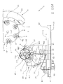
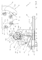
figures 1 and2 are schematic side elevation views of a packer machine according to the present invention, shown with certain parts omitted and illustrated in two respective operating positions; -
figure 3 shows the machine in the operating position offigure 2 , illustrated in a second possible embodiment. - With reference to the accompanying drawings,
numeral 1 denotes a packer machine in accordance with the present invention. - The invention finds application to advantage in the manufacture of soft cigarette packets. It will be appreciated nonetheless that the present invention finds application in systems for manufacturing packets of any given description from a respective wrapping material.
- In detail, the
machine 1 comprises awrapping wheel 3 rotatable about a relative axis X in an anticlockwise direction denoted F1 in the drawings, and furnished peripherally with a plurality of support andtransfer mechanisms 4 equispaced angularly one from the next. - Each
mechanism 4 is designed to support arespective object 2 of substantially parallelepiped appearance, consisting preferably in a group of cigarettes enveloped by a wrapper of metal foil paper, and to transfer theselfsame object 2 along a predetermined path through anassembly station 5 where each one is paired with arespective leaf 6 of wrapping material. - In particular, each
mechanism 4 comprises a substantiallyU-shaped support element 7 mounted freely to the periphery of thewheel 3 and pivotable thus about a respective axis parallel to the aforementioned axis X of the wheel. - Internally, each
support element 7 presents a rigidly associatedgripper 8 holding theobject 2, whilst externally, theelement 7 is furnished withgripping means 9 serving to engage one end of arelative leaf 6 retained by a feed block 10 (described more fully in the course of the present specification), located at theassembly station 5. - The gripping means 9 consist in a
jaw 9a pivotable about a respective axis parallel to the aforementioned axis X of the wheel, by which asingle leaf 6 is separated gradually from thefeed block 10 and transferred, together with arespective object 2, toward a folding station where the packet is formed. - Each
mechanism 4 is capable of movement between two limit positions, the first assumed both at a position A of insertion, in whichobjects 2 supplied by a feed device of conventional type (not illustrated in the drawings) are directed singly and in succession into thegrippers 8, and at a position B in which theleaf 6 is folded partially around theobject 2. - Extending along the feed path downstream of the
assembly station 5 are folding means 11, embodied advantageously as aguide mantle 11a of arched profile, positioned facing toward the wrappingwheel 3. Themantle 11a is furnished with an aspiratingsurface 12 such as will attract aleaf 6 released by theblock 10 to the gripping means 9 associated with eachmechanism 4. Accordingly, as thewrapping wheel 3 rotates, theleaf 6 is drawn taut by the aspirating action of themantle 11a and caused to wrap partially around theobject 2. - The
feed block 10 comprises acarriage 13 and, projecting beneath the carriage, a substantially vertical supportingwall 14. - The supporting
wall 14 carries means, denoted 15, by which to decoil acontinuous strip 16 of wrapping material. The decoiling means 15 comprise two mutuallytangential rollers wrapping wheel 3. Theaforementioned strip 16 is pulled steadily by therollers guide rollers 17 mounted to thecarriage 13. - Positioned beyond the decoiling
means 15 on the downstream side are means 18, also mounted to the aforementioned supportingwall 14, by which theleaves 6 are transferred to theassembly station 5. - In particular, such transfer means 18 comprise an
vacuum roller 19 disposed substantially tangential to the wrappingwheel 3 in such a way that the gripping means 9 associated with eachmechanism 4 can engage the leaves 6 (seefigure 1 ). Thevacuum roller 19 rotates about an axis parallel to the axis X of thewrapping wheel 3, turning in a clockwise direction denoted F2 in the drawings. - The
wall 14 also carries cutting means 20 interacting with thevacuum roller 19, by which thestrip 16 is divided intoleaves 6. - In particular, the cutting means 20 comprise a
cutter wheel 21 rotating tangentially to thevacuum roller 19 and in the opposite direction. The periphery of thewheel 21 carries at least oneblade 22 placed to interact with acorresponding anvil 22a afforded by the cylindrical surface of thevacuum roller 19. Thus, when theroller 19 and thewheel 21 are set in rotation, theblade 22 will strike repeatedly against theanvil 22a, cutting through thecontinuous strip 16 with each stroke to separate asingle leaf 6. - To advantage, the
feed block 10 also incorporates adevice 23 by means of which to mark thecontinuous strip 16, mounted likewise to the supportingwall 14 and operating at the same linear pitch as the cutting means 20. - The
marker device 23 is positioned upstream of the decoilingmeans 15 and serves to make an identification mark on thestrip 16. The mark in question is used as a reference for optical checks that may be conducted on the packet enveloped by therespective leaf 6 of wrapping material. Thedevice 23 might consist, by way of example, in a pair of contrarotatingcylinders 23a designed to leave a graphic imprint on thestrip 16. To this end, themarker device 23 must necessarily be timed to operate synchronously with the cutting means 20 in order to ensure that theleaf 6 will always be marked in a given position. Thus, when theobject 6 is wrapped in the leaf, orlabel 6, the mark will always coincide with a predetermined area of theenveloped object 2. - As readily discernible in the figures of the accompanying drawings, the
feed block 10 is capable of movement along respective guide means 24 between an operating position, occupying theassembly station 5 and supplyingleaves 6 to the wrapping wheel 3 (figure 1 ), and a non-operating position, distanced from theassembly station 5 and not interacting in any way with the wrapping wheel 3 (figure 2 ). - In particular, the guide means 24 will be seen to comprise at least one
rail 25 extending along a direction D followed by thefeed block 10 when set in motion between the operating position and the non-operating position. - The
carriage 13 is coupled to therail 25 and slidable thereon in such a way as to allow the movement of theentire block 10 toward and away from theassembly station 5. - To advantage, the
feed block 10 is also equipped withdrive means 26 mounted above and operating on thecarriage 13 in such a way that the motion of the selfsame carriage along therail 25 can be induced automatically. - With this arrangement, when an operator needs to gain access to the
feed block 10 for inspection and/or adjustment purposes, the drive means 26 are activated to ease thecarriage 13, and consequently thewall 14, away from theassembly station 5. As illustrated infigure 2 , theentire block 10 is advantageously distanced from thewrapping wheel 3 so that the operator can work manually on parts requiring attention. - The
machine 1 disclosed also comprises alifter element 27 associated operationally with thefeed block 10 and serving to detach at least oneleaf 6 when theblock 10 occupies the non-operating position. - More precisely, the
lifter element 27 comprises anarm 28 of which afirst end 28a is anchored rigidly to the supportingwall 14 at a point downstream of theassembly station 5, and a taperedsecond end 28b is offered to the cylindrical surface of thevacuum roller 19. Thesecond end 28a of thearm 28 is insertable between theleaf 6 of wrapping material and the surface of thevacuum roller 19, in such a way as to lift and detach theleaf 6 from theroller 19. - Adopting an alternative solution not illustrated in the accompanying drawings, the
lifter element 27 can be rendered capable of movement between a first position of interaction with the surface of thevacuum roller 19, and a second position in which there is no interaction with theroller 19. - In this instance, the
first end 28a of thearm 28 will be mounted pivotably to the supportingwall 14 so that thesecond end 28b can be rotated toward and away from the respective first position of theelement 27. - Thus, when the
feed block 10 occupies the respective non-operating position, distanced from thewrapping wheel 3, thelifter element 27 will be made to assume the relative first position. In this situation, thesecond end 28b of thearm 28 is inserted between theleaf 6 and the surface of thevacuum roller 19 so as to detach theleaf 6 from theroller 19. To advantage, the operator can then inspect theleaf 6 picked from theblock 10 to check that the line of the cut is correctly positioned and perpendicular to the longitudinal axis of theleaf 6, also that the positioning of the reference notch or imprint made by themarker device 23 is timed correctly in relation to the line of the cut. - When the
block 10 is returned to its operating position, with thevacuum roller 19 tangential to the wrappingwheel 3, thelifter element 27 will be retracted to the second position so as to remain clear of theroller 19 when normal operation is resumed. - According to a further embodiment illustrated in
figure 3 , thelifter element 27 can be separated entirely from the supportingwall 14 and mounted pivotably at a point remote from theassembly station 5. In this instance, when thefeed block 10 is moved into its non-operating position, the cylindrical surface of theroller 19 will be brought by this same movement into a position of proximity to thearm 28 of thelifter element 27. Thereupon, thearm 28 is caused to pivot on a respective axis Y of rotation, swinging through an arc in the direction denoted F3, so as to bring thesecond end 28b into engagement with the cylindrical surface of theroller 19. - When the
block 10 is returned to its operating position, thearm 28 will pivot in the opposite direction to distance thesecond end 28b from theroller 19. - Furthermore, to avoid any interference with the
feed block 10 when set in motion, thelifter element 27 can be translated along its axis Y of rotation by suitable actuators not described in detail, being of conventional type, to a position clear of the direction D along which motion is induced in theblock 10. - It will be seen that the steps performed by the operator when inspecting the
block 10, and picking theleaves 6 off theroller 19, can be completed without difficulty by distancing theblock 10 from thewrapping wheel 3. - Accordingly, having inspected the leaves, or labels 6, the operator will proceed to perform such servicing steps as may be needed, or to adjust the timing of the cutting means 20 and the marker device.
- Advantageously, the various devices forming part of the
machine 1 will present no obstacle to the operator when performing these operations, by virtue of the fact that thefeed block 10 can be distanced from theassembly station 5.
Claims (13)
- A packer machine, comprising: a wrapping wheel (3) rotatable about a respective axis (X), furnished peripherally with a plurality of mechanisms (4) by which objects (2) of substantially parallelepiped appearance are supported and transferred along a predetermined feed path through an assembly station (5) together with respective leaves (6) of wrapping material; and a feed block (10) by which the leaves (6) are supplied to the assembly station (5); characterized in that the feed block (10) is capable of motion along respective guide means (24) between an operating position, occupying the assembly station (5) in such a way that the leaves (6) of wrapping material can be transferred to the wrapping wheel (3), and a non-operating position, distanced from the assembly station (5) and not interacting in any way with the wrapping wheel (3).
- A machine as in claim 1, wherein the feed block (10) comprises drive means (26) by which the selfsame block (10) is set in motion between the operating position and the non-operating position.
- A machine as in preceding claims, wherein guide means (24) comprise at least one rail (25) extending along a respective direction (D) followed by the feed block (10) when in motion between the operating position and the non-operating position.
- A machine as in claim 3, wherein the feed block (10) further comprises a carriage (13) set in motion by the drive means (26) and caused thus to slide along the rail (25) in the direction of movement (D).
- A machine as in claim 4, wherein the feed block (10) comprises: means (15) by which to decoil a continuous strip (16) of wrapping material; cutting means (20) by which the continuous strip (16) is cut into discrete leaves (6); means (18) by which to transfer the leaves (6) to the assembly station (5), and a supporting wall (14) projecting from the carriage (13), to which the decoiling means (15), the cutting means (20) and the transfer means (18) are all mounted.
- A machine as in claim 5, wherein means (18) by which the leaves (6) are transferred at the assembly station (5) comprise a vacuum roller (19) disposed substantially tangential to the wrapping wheel (3).
- A machine as in preceding claims, comprising a lifter element (27) operationally associated with the feed block (10) and serving to detach at least one leaf (6) from the selfsame block (10) when occupying the respective non-operating position.
- A machine as in claim 7 where dependent on claim 6, wherein the lifter element (27) is mounted immovably to the supporting wall (14) at a point downstream of the assembly station (5) and positioned to interact with the cylindrical surface of the vacuum roller (19).
- A machine as in claim 7 where dependent on claim 6, wherein the lifter element (27) is mounted pivotably to the supporting wall (14) at a point downstream of the assembly station (5) and capable of alternating between a first position of interaction with the cylindrical surface of the vacuum roller (19), in which a leaf (6) can be detached from the selfsame surface, and a second position in which there is no interaction with the vacuum roller (19).
- A machine as in claim 9, wherein the lifter element (27) occupies the first position of interaction with the vacuum roller (19) when the feed block (10) is in the operating position, and occupies the second position, distanced from the vacuum roller (19), when the feed block (10) is in the non-operating position.
- A machine as in claims 1 to 6, comprising a lifter element (27) mounted pivotably at a location remote from the assembly station (5) and capable of interacting with the vacuum roller (19) in such a way as to detach at least one leaf (6) from the feed block (10) when the selfsame block is in the respective non-operating position.
- A machine as in claim 11, wherein the lifter element (27) is pivotable on a respective axis (Y) of rotation toward or away from the feed block (10) when occupying the respective non-operating position, and translatable along this same axis (Y) toward or away from the feed block (10) when occupying the selfsame non-operating position.
- A machine as in claims 5 to 12, wherein the feed block (10) comprises a device (23) by means of which to mark the continuous strip (16), operating at a linear pitch identical to that of the strokes made by the cutting means (20).
Applications Claiming Priority (1)
| Application Number | Priority Date | Filing Date | Title |
|---|---|---|---|
| ITBO20070232 ITBO20070232A1 (en) | 2007-04-02 | 2007-04-02 | PACKAGE PACKAGING MACHINE. |
Publications (1)
| Publication Number | Publication Date |
|---|---|
| EP1977974A1 true EP1977974A1 (en) | 2008-10-08 |
Family
ID=39577274
Family Applications (1)
| Application Number | Title | Priority Date | Filing Date |
|---|---|---|---|
| EP08153915A Withdrawn EP1977974A1 (en) | 2007-04-02 | 2008-04-01 | A packer machine |
Country Status (2)
| Country | Link |
|---|---|
| EP (1) | EP1977974A1 (en) |
| IT (1) | ITBO20070232A1 (en) |
Citations (4)
| Publication number | Priority date | Publication date | Assignee | Title |
|---|---|---|---|---|
| EP0619231A1 (en) * | 1993-04-07 | 1994-10-12 | SASIB S.p.A. | Packing machine, particularly a machine for packing cigarettes or the like |
| EP1361158A2 (en) * | 2002-05-06 | 2003-11-12 | G.D S.p.A. | A unit for overwrapping packets |
| EP1415915A1 (en) * | 2002-11-04 | 2004-05-06 | BAUMER S.r.l. | Sleeve type packaging machine, particularly useful for changing film reels |
| US20050005580A1 (en) * | 2003-05-22 | 2005-01-13 | G.D Societa' Per Azioni | Method and unit for packing groups of products |
-
2007
- 2007-04-02 IT ITBO20070232 patent/ITBO20070232A1/en unknown
-
2008
- 2008-04-01 EP EP08153915A patent/EP1977974A1/en not_active Withdrawn
Patent Citations (4)
| Publication number | Priority date | Publication date | Assignee | Title |
|---|---|---|---|---|
| EP0619231A1 (en) * | 1993-04-07 | 1994-10-12 | SASIB S.p.A. | Packing machine, particularly a machine for packing cigarettes or the like |
| EP1361158A2 (en) * | 2002-05-06 | 2003-11-12 | G.D S.p.A. | A unit for overwrapping packets |
| EP1415915A1 (en) * | 2002-11-04 | 2004-05-06 | BAUMER S.r.l. | Sleeve type packaging machine, particularly useful for changing film reels |
| US20050005580A1 (en) * | 2003-05-22 | 2005-01-13 | G.D Societa' Per Azioni | Method and unit for packing groups of products |
Also Published As
| Publication number | Publication date |
|---|---|
| ITBO20070232A1 (en) | 2008-10-03 |
Similar Documents
| Publication | Publication Date | Title |
|---|---|---|
| US7252131B2 (en) | Unit for applying printed slips to packets in packaging machines | |
| JP5657931B2 (en) | Method and apparatus for forming and applying a folded flyer | |
| US4962897A (en) | Web winding machine and method | |
| CA2271141C (en) | Roll-fed labelling apparatus | |
| US6141944A (en) | Continuous product wrapping method and machine | |
| JP4060419B2 (en) | (Printed) band label and method and apparatus for applying it to (cigarette) packets | |
| CN101218989B (en) | Method for transfer of a rod-shaped article in the tobacco industry | |
| JP2010500258A (en) | Method for performing a roll change in a supply unit for supplying a strip-shaped flat material to a packaging machine or similar processing machine, and a supply unit for carrying out this method | |
| EP1035021B1 (en) | Method and device for forming a packet of cigarettes | |
| EP3152143A1 (en) | Tipping paper feed assembly for use in smoking article manufacture | |
| CA1334023C (en) | Core loading device for web-slitting machine | |
| US7036413B2 (en) | Device for the transverse cutting of at least one web in a folding apparatus | |
| EP1642835A1 (en) | A unit for feeding and cutting into lengths a strip of wrapping material | |
| EP1300088B1 (en) | A cigarette maker outfeed unit | |
| EP2110319B1 (en) | A unit and a method for wrapping tobacco products | |
| EP1640268B1 (en) | A unit for overwrapping products, in particular packets, and a relative overwrapping method | |
| EP1361158B1 (en) | A unit for overwrapping packets | |
| EP1294627B1 (en) | Strip feed unit and method | |
| JP2005231026A (en) | Device for cutting the top edge, ground edge and small edge of printed matter | |
| ITBO20070232A1 (en) | PACKAGE PACKAGING MACHINE. | |
| EP1150886B1 (en) | Method and machine for wrapping articles | |
| US2591199A (en) | Apparatus for feeding labels or blanks | |
| JP3931031B2 (en) | Film winding device | |
| KR20170032270A (en) | Slitter for cutting cord band |
Legal Events
| Date | Code | Title | Description |
|---|---|---|---|
| PUAI | Public reference made under article 153(3) epc to a published international application that has entered the european phase |
Free format text: ORIGINAL CODE: 0009012 |
|
| 17P | Request for examination filed |
Effective date: 20080723 |
|
| AK | Designated contracting states |
Kind code of ref document: A1 Designated state(s): AT BE BG CH CY CZ DE DK EE ES FI FR GB GR HR HU IE IS IT LI LT LU LV MC MT NL NO PL PT RO SE SI SK TR |
|
| AX | Request for extension of the european patent |
Extension state: AL BA MK RS |
|
| AKX | Designation fees paid |
Designated state(s): CH DE GB LI TR |
|
| GRAP | Despatch of communication of intention to grant a patent |
Free format text: ORIGINAL CODE: EPIDOSNIGR1 |
|
| GRAS | Grant fee paid |
Free format text: ORIGINAL CODE: EPIDOSNIGR3 |
|
| STAA | Information on the status of an ep patent application or granted ep patent |
Free format text: STATUS: THE APPLICATION IS DEEMED TO BE WITHDRAWN |
|
| 18D | Application deemed to be withdrawn |
Effective date: 20101103 |