EP1977964A1 - Overturn prevention controller for two-wheeled vehicle - Google Patents
Overturn prevention controller for two-wheeled vehicle Download PDFInfo
- Publication number
- EP1977964A1 EP1977964A1 EP06822574A EP06822574A EP1977964A1 EP 1977964 A1 EP1977964 A1 EP 1977964A1 EP 06822574 A EP06822574 A EP 06822574A EP 06822574 A EP06822574 A EP 06822574A EP 1977964 A1 EP1977964 A1 EP 1977964A1
- Authority
- EP
- European Patent Office
- Prior art keywords
- angular velocity
- angle
- wheel
- vehicle body
- vehicle
- Prior art date
- Legal status (The legal status is an assumption and is not a legal conclusion. Google has not performed a legal analysis and makes no representation as to the accuracy of the status listed.)
- Withdrawn
Links
Images




Classifications
-
- A—HUMAN NECESSITIES
- A63—SPORTS; GAMES; AMUSEMENTS
- A63H—TOYS, e.g. TOPS, DOLLS, HOOPS OR BUILDING BLOCKS
- A63H17/00—Toy vehicles, e.g. with self-drive; ; Cranes, winches or the like; Accessories therefor
- A63H17/16—Toy vehicles, e.g. with self-drive; ; Cranes, winches or the like; Accessories therefor in the form of a bicycle, with or without riders thereon
-
- A—HUMAN NECESSITIES
- A63—SPORTS; GAMES; AMUSEMENTS
- A63H—TOYS, e.g. TOPS, DOLLS, HOOPS OR BUILDING BLOCKS
- A63H17/00—Toy vehicles, e.g. with self-drive; ; Cranes, winches or the like; Accessories therefor
- A63H17/21—Toy vehicles, e.g. with self-drive; ; Cranes, winches or the like; Accessories therefor shaped as motorcycles with or without figures
-
- A—HUMAN NECESSITIES
- A63—SPORTS; GAMES; AMUSEMENTS
- A63H—TOYS, e.g. TOPS, DOLLS, HOOPS OR BUILDING BLOCKS
- A63H17/00—Toy vehicles, e.g. with self-drive; ; Cranes, winches or the like; Accessories therefor
- A63H17/26—Details; Accessories
- A63H17/36—Steering-mechanisms for toy vehicles
-
- B—PERFORMING OPERATIONS; TRANSPORTING
- B62—LAND VEHICLES FOR TRAVELLING OTHERWISE THAN ON RAILS
- B62H—CYCLE STANDS; SUPPORTS OR HOLDERS FOR PARKING OR STORING CYCLES; APPLIANCES PREVENTING OR INDICATING UNAUTHORIZED USE OR THEFT OF CYCLES; LOCKS INTEGRAL WITH CYCLES; DEVICES FOR LEARNING TO RIDE CYCLES
- B62H7/00—Devices for learning to ride cycles, not otherwise provided for, e.g. assisting balance
Definitions
- the present invention relates to an overturn prevention control device for a two-wheel vehicle, and in particular, to an overturn prevention control device for a two-wheel vehicle capable of traveling autonomously without a human driver.
- Patent Document 1 describes an autonomous vehicle without a human driver, the autonomous vehicle being capable of making a run that is always approximated to an actual machine in stable and various modes from low to high speeds.
- This autonomous driverless vehicle includes a frame forming a vehicle body, a drive wheel disposed in an end of the frame and rotatable by a prime motor, and a fork mounted to another end of the frame and supporting a steerable wheel so as to allow the steerable wheel to be freely driven and also includes an angular velocity sensor that outputs an angular velocity signal for a fall angle of the vehicle body, an arithmetic unit that generates a steering angle control signal, and an actuator that changes an angle of travel of the steered wheel in accordance with the steering angle control signal output from the arithmetic unit.
- the arithmetic unit includes angular velocity command value generating means for generating an angular velocity command value on the basis of an externally provided travel control signal indicating an angle of travel of the steered wheel, control signal generating means for generating a steering angle control signal to be supplied to the actuator on the basis of the deviation between an angular velocity signal being a detection signal of the angular velocity sensor and the angular velocity command value being an output from the angular velocity command value generating means, and feedback means for feeding the steering angle control signal generated by the control signal generating means back to the angular velocity command value generating means.
- the actuator generates a steering control signal for controlling the steered wheel in a direction in which a deviation in fall angular velocity of the vehicle body during travel is reduced in accordance with the steering angle control signal from the arithmetic unit.
- the steering angle control signal to be supplied to the actuator is generated based on the deviation between the detection signal of the angular velocity sensor and the angular velocity command value generated based on the externally provided travel control signal indicating an angle of travel of the steered wheel.
- obtaining a proper angular velocity command value from an angle of travel of the steered wheel and obtaining a steering angle directly from the deviation between a detected angular velocity value and the angular velocity command value need complicated computation and many parameters. This leads to complicated control, so it is difficult to perform stable autonomous travel.
- a relatively simple control method for preventing a two-wheel vehicle from overturning is illustrated in Fig. 7 .
- This method is a method of obtaining a steering angle from the deviation in inclination angle using the proportional gain G 1 . Therefore, it is advantageous in that computation is simple and, because not many parameters are required, the method is executable in a relatively simple manner.
- an angular velocity sensor typically has a deviation (drift) in detection signal due to changes in environmental temperature or a lapse of time, and this has adverse effects as an offset. Together with the offset, external noise entering the angular velocity sensor 20 affects an angular velocity detection signal. In addition, if the vehicle body is already inclined when the vehicle starts traveling, it affects the inclination angle ⁇ f as a zero-set error ⁇ 0 . Such problems may occur in not only the control method illustrated in Fig. 7 but also the control method described in Patent Document 1.
- Fig. 8 is an actual control block diagram in which error factors (zero-set error ⁇ 0 and offset noise ⁇ ) are added to the block diagram illustrated in Fig. 7 .
- the zero-set error ⁇ 0 is applied to the inclination angle ⁇ f
- the offset noise ⁇ is applied to the angular velocity ⁇ 1 .
- Fig. 9 is an equivalent block diagram into which the block diagram illustrated in Fig. 8 is rewritten.
- the zero-set error ⁇ 0 is directly applied to the inclination angle command value ⁇ r
- the integral of the offset noise ⁇ is also applied to the inclination angle command value ⁇ r .
- the zero-set error urges the vehicle body to incline even when the inclination angle command value ⁇ r is zero, so the path taken by the two-wheel vehicle is a curve.
- an object of preferred embodiments of the present invention is to provide an overturn prevention control device that allows a two-wheel vehicle to perform stable autonomous travel using a relatively simple control loop even when a zero-set error or offset noise is present.
- the present invention is an overturn prevention control device for a two-wheel vehicle having a vehicle body, a steerable front wheel provided to a front end of the vehicle body, an actuator that steers the front wheel, a rear wheel provided to a rear end of the vehicle body, and a rear-wheel driving portion that drives the rear wheel.
- the overturn prevention control device includes an angular velocity sensor and control means for outputting a steering angle command signal ⁇ r for controlling the actuator.
- the angular velocity sensor has a detection axis, is mounted on the vehicle body such that the detection axis is downwardly inclined at a predetermined angle relative to a forward direction of the vehicle body, and detects an angular velocity ⁇ about the detection axis.
- the control means includes integration means for integrating the angular velocity ⁇ to obtain a first angle signal and steering-angle-signal generating means for generating the steering angle command signal ⁇ r using a deviation between the first angle signal and an externally provided second angle signal.
- the first angle is controlled so as to be made near the second angle by inputting of the steering angle command signal ⁇ r into the actuator.
- a traditional angular sensor detects only an angular velocity ⁇ 1 in the lateral direction of inclination of the vehicle body, so the sensor is mounted such that its detection axis faces in the forward direction of the vehicle body (horizontal axis in the direction of travel of the vehicle body).
- the angular velocity sensor is mounted on the vehicle body such that its detection axis is downwardly inclined relative to the forward direction of the vehicle body, so the angular velocity ⁇ containing the angular velocity ⁇ 1 component in the lateral direction of inclination of the vehicle body and the angular velocity ⁇ 2 component in the azimuthal direction is thereby detected.
- the zero-set error merely provides an initial value of the azimuth angle command with a deviation, and, for the offset noise, the integral thereof merely affects the azimuth angle command. That is, the zero-set error and the offset noise are incorporated into the azimuth angle command, and the inclination angle in the lateral direction of inclination is automatically controlled in the internal loop (inclination angle loop).
- the two-wheel vehicle can be prevented from overturning.
- the inclination angle is an angle in the lateral direction of inclination of the vehicle body
- the steering angle is an angle that represents the direction of the front wheel.
- the azimuth angle is an angle that represents the direction of travel of the vehicle body
- the mounting angle is an angle of downward tilt of the detection axis of the angular velocity sensor relative to the forward horizontal axis. Because the detection axis of the angular velocity sensor extends in the longitudinal direction, setting the detection axis using an angle of upward tilt to the backward horizontal axis is equal to the above.
- a mounting angle ⁇ of the detection axis of the angular velocity sensor relative to a horizontal axis may preferably be an angle that allows an angular velocity ⁇ 1 in a lateral direction of inclination of the vehicle body and an angular velocity ⁇ 2 in an azimuthal direction to be extracted from the angular velocity ⁇ .
- the optimal value of the mounting angle ⁇ varies depending on the structure of the vehicle body (e.g., the mass or the position of the center of gravity), the traveling speed of the two-wheel vehicle, or other factors.
- the mounting angle ⁇ may preferably be at least an angle that allows the angular velocity ⁇ 1 in the lateral direction of inclination of the vehicle body and the angular velocity ⁇ 2 in the azimuthal direction to be extracted from the angular velocity ⁇ . If the mounting angle ⁇ is too small, the angular velocity ⁇ 2 in the azimuthal direction would be difficult to extract. If the mounting angle ⁇ is too large, the azimuth angle loop gain would be significantly large and control would be unstable.
- the second angle signal can be given by a target azimuth angle ⁇ sin ⁇ . That is, because the second angle signal being a command signal has only an azimuth angle component, the direction of travel of the vehicle body can be directed in a target direction (orientation). In other words, the direction of travel is also controllable. In consideration of that the azimuth angle command is affected by the offset and noise, the vehicle can also be accurately controlled to a target position by correction of the position of the vehicle using other position recognition means.
- the angular velocity sensor is mounted on the vehicle body such that its detection axis is downwardly inclined relative to the forward direction of the vehicle body. Therefore, similar advantages to those obtained when the azimuth angle loop is set outside the inclination angle loop are obtainable.
- This causes the zero-set error and the offset noise to be incorporated into the azimuth angle command, and causes the inclination angle in the lateral direction of inclination to be automatically controlled in the internal loop (inclination angle loop). Accordingly, the two-wheel vehicle can be reliably prevented from overturning.
- the control means for outputting a steering angle command signal can be constructed of the integration means and the simple arithmetic unit having a proportional gain, the structure is simple and easy to make. Best Modes for Carrying Out the Invention
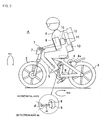
- Figs. 1 to 3 illustrate a first embodiment in which an overturn prevention control device according to the present invention is applied to a bicycle robot.
- the bicycle robot A includes a steering handlebar 1, a front wheel 2 steerable by the steering handlebar 1, a rear wheel 3, a rear-wheel driving motor 4 that drives the rear wheel 3, a frame 5 supporting the front wheel 2 and the rear wheel 3 such that they are freely rotatable, a doll 6 mounted on the frame 5, and an actuator 7 that steers the handlebar 1 (front wheel 2).
- the actuator 7 is provided on the central portion of the handlebar 1.
- the actuator 7 may be provided on any position or take any form as long as it can steer the front wheel 2.
- the front wheel 2 may be steered by an arm of the doll 6 via the handlebar 1.
- the rear wheel 3 is driven by the rear-wheel driving motor 4 via a roller 4a.
- the rear-wheel driving motor 4 may drive the shaft of the rear wheel 3.
- the rear wheel 3 may be driven via a chain by the doll 6 pedaling the bicycle.
- an internal combustion engine or other components may be used in place of the driving motor 4.
- the frame 5 is equipped with an angular velocity sensor 8 such that a detection axis 8a thereof is downwardly inclined at a predetermined angle ⁇ relative to the forward direction of the vehicle body of the bicycle robot A.
- the angular velocity sensor 8 can detect an angular velocity ⁇ about the detection axis 8a.
- the mounting angle ⁇ of the angular velocity sensor 8 may preferably be an angle that allows an angular velocity ⁇ 1 in a lateral direction of inclination of the vehicle body (including the frame 5 and the doll 6) and an angular velocity ⁇ 2 in an azimuthal direction to be extracted from the angular velocity ⁇ , and may preferably be, for example, on the order of approximately 4° to 8°.
- the optimal value of the mounting angle ⁇ varies depending on the structure of the vehicle body (e.g., the mass or the position of the center of gravity), the traveling speed, or other factors, so the mounting angle ⁇ is not limited to the above angle range.
- the inclination angle ⁇ is an angle in a lateral direction of inclination of the vehicle body (rear wheel 3) relative to a vertical direction.
- the steering angle ⁇ is an angle that represents the direction of the front wheel relative to the direction of travel of the vehicle body.
- the azimuth angle ⁇ is an angle that represents the direction of travel of the vehicle body relative to a reference direction (for example, the north).
- the mounting angle ⁇ is a tilt angle of the detection axis 8a relative to the horizontal axis (in the forward direction), as previously described.
- the angular velocity ⁇ is an angular velocity about the detection axis 8a.
- the angular velocity ⁇ 1 is an angular velocity in a lateral direction of inclination of the vehicle body.
- the angular velocity ⁇ 2 is an angle velocity in an azimuthal direction.
- An inertia rotor 9, a balance motor 10 that drives the inertia rotor 9, and an encoder 11 that measures a rotation angle of the balance motor 10 are mounted in the chest of the doll 6.
- the rotating shaft of each of the inertia rotor 9 and the motor 10 faces in a substantially longitudinal direction of the bicycle A.
- the substantially longitudinal direction here indicates that it includes an exact longitudinal direction and can be slightly displaced upward or downward therefrom.
- a control substrate 12 that controls the rear-wheel driving motor 4, the steering actuator 7, the balance motor 10, and other components and a battery 13 are mounted in the back of the doll 6.
- the vehicle can be prevented from overturning by maintaining its balance by steering the handlebar 1 (front wheel 2). Specifically, the vehicle can be prevented from overturning by steering the handlebar 1 in a direction in which the vehicle body is inclined.
- the vehicle is controlled such that the balance is maintained by exploiting a reaction occurring when the inertia rotor 9 is driven. Control for preventing an overturn by use of the inertia rotor 9 is described in Japanese Patent Application No. 2005-348373 filed by the applicant of the present invention, so the description thereof is omitted here.
- Fig. 4 illustrates one example of a control block for performing overturn prevention control while the bicycle robot A travels.
- the integral of an output from the angular velocity sensor is made to be a feedback signal, as in the case of Fig. 8 , and the same reference numerals are used as in Fig. 8 for the same portions and the redundant description is omitted.
- the offset noise signal ⁇ is added to the angular velocity signal ⁇ , and the result is integrated by an integrator 21.
- the zero-set error ⁇ 0 is added to the integrated signal, and the result becomes a feedback signal R f .
- the deviation between the feedback signal R f and an input command signal R r is input into arithmetic means 22, and a steering angle command value ⁇ r is formed.
- the command value ⁇ r is output to the actuator 7, and the handlebar 1 (front wheel 2) is steered.
- the command signal R r will be described later.
- Fig. 5 is an equivalent block diagram that illustrates the angular velocity ⁇ in the block diagram of Fig. 4 in such a way that the angular velocity ⁇ is divided into the angular velocity ⁇ 1 component in the lateral direction of inclination and the angular velocity ⁇ 2 component in the azimuthal direction.
- the zero-set error ⁇ 0 is directly applied to the input command signal R r
- the integral of the offset noise ⁇ evaluated by an integrator 21a is also applied to the command signal R r .
- Fig. 6A is an equivalent block diagram into which the block diagram of Fig. 5 is further rewritten.
- Fig. 6B is a block diagram in which the bicycle in a steady travel state (input R r is input so as to increase at a constant speed in a ramp-like manner) is added to Fig. 6A , illustrating an overall control system.
- the bicycle A is a bicycle model that includes the actuator 7 for steering the handlebar.
- the handlebar 1 is steered in accordance with the handlebar steering angle command ⁇ r and a movement of some kind is performed by the bicycle A in response thereto, the inclination angle ⁇ is thereby determined.
- the centripetal force tending to travel in a curve is represented by mg tan ⁇ ⁇ mg ⁇ (m: the mass of the bicycle, g: the acceleration of gravity).
- the deviation between the inclination angle command ⁇ r and the feedback signal ⁇ f obtained by the integration of the angular velocity ⁇ 1 in the lateral direction of inclination performed by the integrator 21c is determined.
- the product of cos ⁇ and G 1 is the inclination angle loop gain.
- the arithmetic means 22 having the gain G 1 may be basically the same as the arithmetic means 22 having the inclination angle loop gain G 1 illustrated in Fig. 7 .
- the steering angle command ⁇ r is input into the bicycle A (including the actuator 7).
- the output inclination angle ⁇ in the lateral direction of inclination is transformed into the angular velocity ⁇ 1 by a differentiator 29.
- a multiplication 30 is performed such that the inclination angle ⁇ is multiplied by a gain g/v, and the angular velocity ⁇ 2 in the azimuthal direction is thereby obtained.
- the angular velocity ⁇ 2 is integrated by an integrator 31, the azimuth angle is obtainable.
- the azimuth angle command ⁇ r is a constant, the inclination angle ⁇ converges to 0°.
- the response in the azimuthal direction can be freely changed.
- a target azimuth angle ⁇ sin ⁇ is input as the command signal R r , the orientation can be controlled.
- the azimuth angle command is affected by the offset and the noise, and thus, the bicycle can be guided to a target position by correction of the position using image recognition performed by other position recognition means, for example, a mounted camera if needed.
- the angular velocity ⁇ output from the angular velocity sensor 8 has the azimuth angle component ⁇ 2 and the angular velocity component ⁇ 1 , similar advantages to those occurring when the azimuth angle loop is set outside the inclination angle loop are obtainable.
- the integral thereof merely affects the azimuth angle command. That is, the zero-set error and the offset noise are incorporated into the azimuth angle command ⁇ r , and the inclination angle is automatically controlled in the internal loop (inclination angle loop). Accordingly, the two-wheel vehicle can be reliably prevented from overturning.
- the prevention of overturning of the bicycle robot is described.
- the present invention is not limited to this embodiment.
- the present invention is applicable to an automatically controlled two-wheel vehicle with a human driver and other types of vehicle.
- example overturn prevention control using the inertia rotor 9 during halts or while the vehicle travels at a very slow speed is described.
- the present invention is applicable to a bicycle that does not have the inertia rotor 9. In this case, if the vehicle body is inclined when the vehicle starts traveling, it affects the azimuth angle.
- the initial inclination angle ⁇ of the vehicle body is substantially 0° and substantially no zero-set error occurs, so it can be accurately controlled to a target orientation.
Landscapes
- Engineering & Computer Science (AREA)
- Mechanical Engineering (AREA)
- Motorcycle And Bicycle Frame (AREA)
- Steering Control In Accordance With Driving Conditions (AREA)
- Toys (AREA)
- Steering Devices For Bicycles And Motorcycles (AREA)
- Control Of Position, Course, Altitude, Or Attitude Of Moving Bodies (AREA)
Abstract
Description
- The present invention relates to an overturn prevention control device for a two-wheel vehicle, and in particular, to an overturn prevention control device for a two-wheel vehicle capable of traveling autonomously without a human driver.
- There are known autonomous vehicles without a human driver using an electric motor or an internal-combustion engine as a prime motor and being controlled wirelessly or automatically. When traveling straight, such a vehicle can maintain its balance by steering right for a rightward tilt of the body of the vehicle and steering left for a leftward tilt of the vehicle body. When traveling in a curve, the vehicle can set a target value for a tilt angle of the vehicle body to a direction inclined from a vertical direction, and can steer right for a rightward tilt and steer left for a leftward tilt by using the set angle as the reference. In either case, it is necessary to estimate a tilt angle of the vehicle body.
-
Patent Document 1 describes an autonomous vehicle without a human driver, the autonomous vehicle being capable of making a run that is always approximated to an actual machine in stable and various modes from low to high speeds. This autonomous driverless vehicle includes a frame forming a vehicle body, a drive wheel disposed in an end of the frame and rotatable by a prime motor, and a fork mounted to another end of the frame and supporting a steerable wheel so as to allow the steerable wheel to be freely driven and also includes an angular velocity sensor that outputs an angular velocity signal for a fall angle of the vehicle body, an arithmetic unit that generates a steering angle control signal, and an actuator that changes an angle of travel of the steered wheel in accordance with the steering angle control signal output from the arithmetic unit. The arithmetic unit includes angular velocity command value generating means for generating an angular velocity command value on the basis of an externally provided travel control signal indicating an angle of travel of the steered wheel, control signal generating means for generating a steering angle control signal to be supplied to the actuator on the basis of the deviation between an angular velocity signal being a detection signal of the angular velocity sensor and the angular velocity command value being an output from the angular velocity command value generating means, and feedback means for feeding the steering angle control signal generated by the control signal generating means back to the angular velocity command value generating means. The actuator generates a steering control signal for controlling the steered wheel in a direction in which a deviation in fall angular velocity of the vehicle body during travel is reduced in accordance with the steering angle control signal from the arithmetic unit. - It is a matter of course that, when the vehicle body falls, the direction of the steered wheel is controlled in a direction in which the fall angle is reduced. For the above autonomous driverless two-wheel vehicle, the steering angle control signal to be supplied to the actuator is generated based on the deviation between the detection signal of the angular velocity sensor and the angular velocity command value generated based on the externally provided travel control signal indicating an angle of travel of the steered wheel. However, obtaining a proper angular velocity command value from an angle of travel of the steered wheel and obtaining a steering angle directly from the deviation between a detected angular velocity value and the angular velocity command value need complicated computation and many parameters. This leads to complicated control, so it is difficult to perform stable autonomous travel.
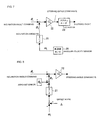
- One example of a relatively simple control method for preventing a two-wheel vehicle from overturning is illustrated in
Fig. 7 . In this method, an angular velocity ω1 in a lateral direction of inclination of a vehicle body by use of an angular velocity sensor 20, the angular velocity ω1 is integrated by use of anintegrator 21 to obtain an inclination angle θf in the lateral direction of inclination of the vehicle body, the deviation between the obtained inclination angle θf and an inclination angle command value θr is input intoarithmetic means 22 having a proportional gain G1 to generate a steering angle command value δr, and the generated command value δr is output to anactuator 23. This method is a method of obtaining a steering angle from the deviation in inclination angle using the proportional gain G1. Therefore, it is advantageous in that computation is simple and, because not many parameters are required, the method is executable in a relatively simple manner. - However, an angular velocity sensor typically has a deviation (drift) in detection signal due to changes in environmental temperature or a lapse of time, and this has adverse effects as an offset. Together with the offset, external noise entering the angular velocity sensor 20 affects an angular velocity detection signal. In addition, if the vehicle body is already inclined when the vehicle starts traveling, it affects the inclination angle θf as a zero-set error θ0. Such problems may occur in not only the control method illustrated in
Fig. 7 but also the control method described inPatent Document 1. -
Fig. 8 is an actual control block diagram in which error factors (zero-set error θ0 and offset noise Δ) are added to the block diagram illustrated inFig. 7 . As illustrated inFig. 8 , the zero-set error θ0 is applied to the inclination angle θf, and the offset noise Δ is applied to the angular velocity ω1. -
Fig. 9 is an equivalent block diagram into which the block diagram illustrated inFig. 8 is rewritten. As illustrated inFig. 9 , the zero-set error θ0 is directly applied to the inclination angle command value θr, and the integral of the offset noise Δ is also applied to the inclination angle command value θr. As a result, the zero-set error urges the vehicle body to incline even when the inclination angle command value θr is zero, so the path taken by the two-wheel vehicle is a curve. The integral of the offset noise Δ affects the inclination angle command value θr, and the two-wheel vehicle obeys the inclination angle command value θr containing the integral of the offset noise Δ, so the actual inclination angle continues to increase. This causes the two-wheel vehicle to overturn in a short time. As described above, although the control method illustrated inFig. 7 is a simple control method, a problem in which it is difficult to perform stable autonomous travel due to the zero-set error θ0 and offset noise Δ exists in actual control.
Patent Document 1: Japanese Registered Utility Model No.2577593 - Accordingly, an object of preferred embodiments of the present invention is to provide an overturn prevention control device that allows a two-wheel vehicle to perform stable autonomous travel using a relatively simple control loop even when a zero-set error or offset noise is present. Means for Solving the Problems
- The present invention is an overturn prevention control device for a two-wheel vehicle having a vehicle body, a steerable front wheel provided to a front end of the vehicle body, an actuator that steers the front wheel, a rear wheel provided to a rear end of the vehicle body, and a rear-wheel driving portion that drives the rear wheel. The overturn prevention control device includes an angular velocity sensor and control means for outputting a steering angle command signal δr for controlling the actuator. The angular velocity sensor has a detection axis, is mounted on the vehicle body such that the detection axis is downwardly inclined at a predetermined angle relative to a forward direction of the vehicle body, and detects an angular velocity ω about the detection axis. The control means includes integration means for integrating the angular velocity ω to obtain a first angle signal and steering-angle-signal generating means for generating the steering angle command signal δr using a deviation between the first angle signal and an externally provided second angle signal. The first angle is controlled so as to be made near the second angle by inputting of the steering angle command signal δr into the actuator.
- A traditional angular sensor detects only an angular velocity ω1 in the lateral direction of inclination of the vehicle body, so the sensor is mounted such that its detection axis faces in the forward direction of the vehicle body (horizontal axis in the direction of travel of the vehicle body). In contrast, in the present invention, the angular velocity sensor is mounted on the vehicle body such that its detection axis is downwardly inclined relative to the forward direction of the vehicle body, so the angular velocity ω containing the angular velocity ω1 component in the lateral direction of inclination of the vehicle body and the angular velocity ω2 component in the azimuthal direction is thereby detected. By integration of the angular velocity ω to obtain a first angle signal, generation of a steering angle command signal δr using the deviation between the first angle signal and an externally provided second angle signal, input of the steering angle command signal δr into the actuator, similar advantages to those obtained when an azimuth angle loop is set outside an inclination angle loop are obtainable. The zero-set error merely provides an initial value of the azimuth angle command with a deviation, and, for the offset noise, the integral thereof merely affects the azimuth angle command. That is, the zero-set error and the offset noise are incorporated into the azimuth angle command, and the inclination angle in the lateral direction of inclination is automatically controlled in the internal loop (inclination angle loop). Accordingly, the two-wheel vehicle can be prevented from overturning. Here, the inclination angle is an angle in the lateral direction of inclination of the vehicle body, and the steering angle is an angle that represents the direction of the front wheel. In addition, the azimuth angle is an angle that represents the direction of travel of the vehicle body, and the mounting angle is an angle of downward tilt of the detection axis of the angular velocity sensor relative to the forward horizontal axis. Because the detection axis of the angular velocity sensor extends in the longitudinal direction, setting the detection axis using an angle of upward tilt to the backward horizontal axis is equal to the above.
- According to a preferred embodiment, a mounting angle φ of the detection axis of the angular velocity sensor relative to a horizontal axis may preferably be an angle that allows an angular velocity ω1 in a lateral direction of inclination of the vehicle body and an angular velocity ω2 in an azimuthal direction to be extracted from the angular velocity ω. The optimal value of the mounting angle φ varies depending on the structure of the vehicle body (e.g., the mass or the position of the center of gravity), the traveling speed of the two-wheel vehicle, or other factors. The mounting angle φ may preferably be at least an angle that allows the angular velocity ω1 in the lateral direction of inclination of the vehicle body and the angular velocity ω2 in the azimuthal direction to be extracted from the angular velocity ω. If the mounting angle φ is too small, the angular velocity ω2 in the azimuthal direction would be difficult to extract. If the mounting angle φ is too large, the azimuth angle loop gain would be significantly large and control would be unstable.
- According to a preferred embodiment, the angular velocity ω detected by the angular velocity sensor can be represented by

where φ is a mounting angle of the detection axis relative to a horizontal axis, ω1 is an angular velocity in a lateral direction of inclination of the vehicle body, and ω2 is an angular velocity in an azimuthal direction. - According to a preferred embodiment, the second angle signal can be given by a target azimuth angle × sin φ. That is, because the second angle signal being a command signal has only an azimuth angle component, the direction of travel of the vehicle body can be directed in a target direction (orientation). In other words, the direction of travel is also controllable. In consideration of that the azimuth angle command is affected by the offset and noise, the vehicle can also be accurately controlled to a target position by correction of the position of the vehicle using other position recognition means.
- As described above, according to the overturn prevention control device for a two-wheel vehicle in accordance with the present invention, the angular velocity sensor is mounted on the vehicle body such that its detection axis is downwardly inclined relative to the forward direction of the vehicle body. Therefore, similar advantages to those obtained when the azimuth angle loop is set outside the inclination angle loop are obtainable. This causes the zero-set error and the offset noise to be incorporated into the azimuth angle command, and causes the inclination angle in the lateral direction of inclination to be automatically controlled in the internal loop (inclination angle loop). Accordingly, the two-wheel vehicle can be reliably prevented from overturning. Additionally, because the control means for outputting a steering angle command signal can be constructed of the integration means and the simple arithmetic unit having a proportional gain, the structure is simple and easy to make. Best Modes for Carrying Out the Invention
- Preferred embodiments of the present invention will be described below with reference to the drawings.
-
Figs. 1 to 3 illustrate a first embodiment in which an overturn prevention control device according to the present invention is applied to a bicycle robot. The bicycle robot A includes asteering handlebar 1, afront wheel 2 steerable by the steeringhandlebar 1, arear wheel 3, a rear-wheel driving motor 4 that drives therear wheel 3, aframe 5 supporting thefront wheel 2 and therear wheel 3 such that they are freely rotatable, adoll 6 mounted on theframe 5, and anactuator 7 that steers the handlebar 1 (front wheel 2). - In this example, the
actuator 7 is provided on the central portion of thehandlebar 1. However, theactuator 7 may be provided on any position or take any form as long as it can steer thefront wheel 2. For example, thefront wheel 2 may be steered by an arm of thedoll 6 via thehandlebar 1. In this example, therear wheel 3 is driven by the rear-wheel driving motor 4 via aroller 4a. However, the present invention is not limited to this example. The rear-wheel driving motor 4 may drive the shaft of therear wheel 3. Alternatively, therear wheel 3 may be driven via a chain by thedoll 6 pedaling the bicycle. In addition, an internal combustion engine or other components may be used in place of the drivingmotor 4. - The
frame 5 is equipped with anangular velocity sensor 8 such that adetection axis 8a thereof is downwardly inclined at a predetermined angle φ relative to the forward direction of the vehicle body of the bicycle robot A. Theangular velocity sensor 8 can detect an angular velocity ω about thedetection axis 8a. The mounting angle φ of the angular velocity sensor 8 (tilt angle of thedetection axis 8a to a horizontal axis) may preferably be an angle that allows an angular velocity ω1 in a lateral direction of inclination of the vehicle body (including theframe 5 and the doll 6) and an angular velocity ω2 in an azimuthal direction to be extracted from the angular velocity ω, and may preferably be, for example, on the order of approximately 4° to 8°. The optimal value of the mounting angle φ varies depending on the structure of the vehicle body (e.g., the mass or the position of the center of gravity), the traveling speed, or other factors, so the mounting angle φ is not limited to the above angle range. - Here, the symbols used in the description below are defined. As illustrated in
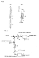
Fig. 3 , the inclination angle θ is an angle in a lateral direction of inclination of the vehicle body (rear wheel 3) relative to a vertical direction. The steering angle δ is an angle that represents the direction of the front wheel relative to the direction of travel of the vehicle body. The azimuth angle ψ is an angle that represents the direction of travel of the vehicle body relative to a reference direction (for example, the north). The mounting angle φ is a tilt angle of thedetection axis 8a relative to the horizontal axis (in the forward direction), as previously described. The angular velocity ω is an angular velocity about thedetection axis 8a. The angular velocity ω1 is an angular velocity in a lateral direction of inclination of the vehicle body. The angular velocity ω2 is an angle velocity in an azimuthal direction. - An
inertia rotor 9, abalance motor 10 that drives theinertia rotor 9, and anencoder 11 that measures a rotation angle of thebalance motor 10 are mounted in the chest of thedoll 6. The rotating shaft of each of theinertia rotor 9 and themotor 10 faces in a substantially longitudinal direction of the bicycle A. The substantially longitudinal direction here indicates that it includes an exact longitudinal direction and can be slightly displaced upward or downward therefrom. Acontrol substrate 12 that controls the rear-wheel driving motor 4, thesteering actuator 7, thebalance motor 10, and other components and abattery 13 are mounted in the back of thedoll 6. - During normal travel, the vehicle can be prevented from overturning by maintaining its balance by steering the handlebar 1 (front wheel 2). Specifically, the vehicle can be prevented from overturning by steering the
handlebar 1 in a direction in which the vehicle body is inclined. During halts or while traveling at a very low speed, because it is difficult to maintain the balance by steering thehandlebar 1 alone, the vehicle is controlled such that the balance is maintained by exploiting a reaction occurring when theinertia rotor 9 is driven. Control for preventing an overturn by use of theinertia rotor 9 is described in Japanese Patent Application No.2005-348373 -
Fig. 4 illustrates one example of a control block for performing overturn prevention control while the bicycle robot A travels. In this control block, the integral of an output from the angular velocity sensor is made to be a feedback signal, as in the case ofFig. 8 , and the same reference numerals are used as inFig. 8 for the same portions and the redundant description is omitted. - The angular velocity ω detected by the
angular velocity sensor 8 contains the angular velocity ω1 component in a lateral direction of inclination of the vehicle body and the angular velocity ω2 component in an azimuthal direction, and it can be represented by the following equation:
where φ is the mounting angle. - As is apparent from
Fig. 4 , the offset noise signal Δ is added to the angular velocity signal ω, and the result is integrated by anintegrator 21. The zero-set error θ0 is added to the integrated signal, and the result becomes a feedback signal Rf. The deviation between the feedback signal Rf and an input command signal Rr is input intoarithmetic means 22, and a steering angle command value δr is formed. The command value δr is output to theactuator 7, and the handlebar 1 (front wheel 2) is steered. The command signal Rr will be described later. -
Fig. 5 is an equivalent block diagram that illustrates the angular velocity ω in the block diagram ofFig. 4 in such a way that the angular velocity ω is divided into the angular velocity ω1 component in the lateral direction of inclination and the angular velocity ω2 component in the azimuthal direction. As is apparent fromFig. 5 , the zero-set error θ0 is directly applied to the input command signal Rr, and the integral of the offset noise Δ evaluated by anintegrator 21a is also applied to the command signal Rr. A multiplication 24 is performed such that the angular velocity ω2 in the azimuthal direction is multiplied by a gain (= sin φ), the result is integrated by anintegrator 21b, and a feedback signal ψf in the azimuthal direction is obtained. Similarly, amultiplication 25 is performed such that the angular velocity ω1 in the lateral direction of inclination is multiplied by a gain (= cos φ), the result is integrated by anintegrator 21c, and a feedback signal θf in the lateral direction of inclination is obtained. -
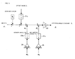
Fig. 6A is an equivalent block diagram into which the block diagram ofFig. 5 is further rewritten.Fig. 6B is a block diagram in which the bicycle in a steady travel state (input Rr is input so as to increase at a constant speed in a ramp-like manner) is added toFig. 6A , illustrating an overall control system. - In
Fig. 6B , the bicycle A is a bicycle model that includes theactuator 7 for steering the handlebar. When thehandlebar 1 is steered in accordance with the handlebar steering angle command δr and a movement of some kind is performed by the bicycle A in response thereto, the inclination angle θ is thereby determined. When the inclination angle is θ, the centripetal force tending to travel in a curve is represented by
mg tan θ ≈ mg θ (m: the mass of the bicycle, g: the acceleration of gravity). - The centrifugal force is represented as mvω2 where v is the velocity of the bicycle A and ω2 is the azimuth angular velocity. Because these two forces are in balance, the following relationship is satisfied:

As a result, as illustrated inFig. 6B , an inclination angle loop can be written such that it is placed within an azimuth angle loop, and thus, both the inclination angle loop and the azimuth angle loop can be stabilized. - The detailed description of
Fig. 6B will be provided. After the zero-set error θ0 and the integral of the offset noise Δ are applied to the command signal Rr, amultiplication 26 is performed such that the resultant command value is multiplied by a gain (= 1/sin φ), and the azimuth angle command ψr is obtained. The deviation between the azimuth angle command ψr and the feedback signal ψf obtained by the integration of the angular velocity ω2 in the azimuthal direction performed by theintegrator 21b is determined. Amultiplication 27 is performed such that this deviation (= ψr - ψf) is multiplied by the azimuth angle loop gain (= tan φ), and the inclination angle command θr is obtained. The deviation between the inclination angle command θr and the feedback signal θf obtained by the integration of the angular velocity ω1 in the lateral direction of inclination performed by theintegrator 21c is determined. When amultiplication 28 is performed such that this deviation (= θr - θf) is multiplied by a gain (= cos φ) and amultiplication 22 is performed such that the resultant is multiplied by the gain G1, the steering angle command δr is thereby obtained. In this case, the product of cos φ and G1 is the inclination angle loop gain. The arithmetic means 22 having the gain G1 may be basically the same as the arithmetic means 22 having the inclination angle loop gain G1 illustrated inFig. 7 . - The steering angle command δr is input into the bicycle A (including the actuator 7). The output inclination angle θ in the lateral direction of inclination is transformed into the angular velocity ω1 by a
differentiator 29. Amultiplication 30 is performed such that the inclination angle θ is multiplied by a gain g/v, and the angular velocity ω2 in the azimuthal direction is thereby obtained. When the angular velocity ω2 is integrated by anintegrator 31, the azimuth angle is obtainable. - As is apparent from
Fig. 6B , when the azimuth angle command ψr is a constant, the inclination angle θ converges to 0°. The azimuth angle loop gain (= tan φ) can be freely set in accordance with the mounting angle φ of theangular velocity sensor 8. The response in the azimuthal direction can be freely changed. When a target azimuth angle × sin φ is input as the command signal Rr, the orientation can be controlled. The azimuth angle command is affected by the offset and the noise, and thus, the bicycle can be guided to a target position by correction of the position using image recognition performed by other position recognition means, for example, a mounted camera if needed. - As described above, because the angular velocity ω output from the
angular velocity sensor 8 has the azimuth angle component ω2 and the angular velocity component ω1, similar advantages to those occurring when the azimuth angle loop is set outside the inclination angle loop are obtainable. The zero-set error merely provides an initial value of the azimuth angle command ψr with a deviation. Therefore, if the vehicle body is inclined in the initial state, it can be immediately returned to an upright position (θ = 0°). For the offset noise, the integral thereof merely affects the azimuth angle command. That is, the zero-set error and the offset noise are incorporated into the azimuth angle command ψr, and the inclination angle is automatically controlled in the internal loop (inclination angle loop). Accordingly, the two-wheel vehicle can be reliably prevented from overturning. - In the foregoing embodiment, the prevention of overturning of the bicycle robot is described. However, the present invention is not limited to this embodiment. The present invention is applicable to an automatically controlled two-wheel vehicle with a human driver and other types of vehicle. In the foregoing embodiment, example overturn prevention control using the
inertia rotor 9 during halts or while the vehicle travels at a very slow speed is described. However, it is, of course, understood that the present invention is applicable to a bicycle that does not have theinertia rotor 9. In this case, if the vehicle body is inclined when the vehicle starts traveling, it affects the azimuth angle. In contrast to this, for a bicycle that controls its balance using theinertia rotor 9 during halts, the initial inclination angle θ of the vehicle body is substantially 0° and substantially no zero-set error occurs, so it can be accurately controlled to a target orientation. -
-
Fig. 1 is a perspective view of one embodiment of a bicycle robot to which an overturn prevention control device according to the present invention is applied. -
Fig. 2 is a side view of the bicycle robot. -
Fig. 3 is an illustration that shows definitions of symbols used for describing an overturn prevention control device according to the present invention. -
Fig. 4 is a block diagram of an overturn prevention control device according to the present invention. -
Fig. 5 is an equivalent block diagram in which the block diagram ofFig. 4 is resolved into angular velocity components. -
Fig. 6A is an equivalent block diagram into which the block diagram ofFig. 5 is further rewritten. -
Fig. 6B is a block diagram in which a bicycle being in a steady travel state is added toFig. 6A , illustrating an overall control system. -
Fig. 7 is an ideal block diagram of an overturn prevention control device being a reference example. -
Fig. 8 is an actual block diagram in which error factors are added to the block diagram ofFig. 7 . -
Fig. 9 is an equivalent block diagram into which the block diagram ofFig. 8 is rewritten. -
- A bicycle robot (body)
- 1 steering handlebar (steering portion)
- 2 front wheel
- 3 rear wheel
- 4 rear-wheel driving motor (rear-wheel driving portion)
- 5 frame
- 6 doll
- 7 steering actuator
- 8 angular velocity sensor
- 8a detection axis
- 9 inertia rotor
- 10 balance motor
- 11 encoder (rotation sensor)
- 12 control substrate
- 13 battery
Claims (4)
- An overturn prevention control device for a two-wheel vehicle having a vehicle body, a steerable front wheel provided to a front end of the vehicle body, an actuator that steers the front wheel, a rear wheel provided to a rear end of the vehicle body, and a rear-wheel driving portion that drives the rear wheel, the overturn prevention control device comprising:an angular velocity sensor having a detection axis, being mounted on the vehicle body such that the detection axis is downwardly inclined at a predetermined angle relative to a forward direction of the vehicle body, and detecting an angular velocity ω about the detection axis and control means for outputting a steering angle command signal δr for controlling the actuator,wherein the control means includes integration means for integrating the angular velocity ω to obtain a first angle signal and steering-angle-signal generating means for generating the steering angle command signal δr using a deviation between the first angle signal and an externally provided second angle signal, and
wherein the first angle is controlled so as to be made near the second angle by inputting of the steering angle command signal δr into the actuator. - The overturn prevention control device for a two-wheel vehicle according to Claim 1, wherein a mounting angle φ of the detection axis of the angular velocity sensor relative to a horizontal axis is an angle that allows an angular velocity ω1 in a lateral direction of inclination of the vehicle body and an angular velocity ω2 in an azimuthal direction to be extracted from the angular velocity ω.
- The overturn prevention control device for a two-wheel vehicle according to Claim 1 or 2, wherein the angular velocity ω detected by the angular velocity sensor is represented by

where φ is a mounting angle of the detection axis relative to a horizontal axis, ω1 is an angular velocity in a lateral direction of inclination of the vehicle body, and ω2 is an angular velocity in an azimuthal direction. - The overturn prevention control device for a two-wheel vehicle according to Claim 3, wherein the second angle signal is given by a target azimuth angle × sin φ.
Applications Claiming Priority (2)
| Application Number | Priority Date | Filing Date | Title |
|---|---|---|---|
| JP2006018471 | 2006-01-27 | ||
| PCT/JP2006/321617 WO2007086176A1 (en) | 2006-01-27 | 2006-10-30 | Overturn prevention controller for two-wheeled vehicle |
Publications (2)
| Publication Number | Publication Date |
|---|---|
| EP1977964A1 true EP1977964A1 (en) | 2008-10-08 |
| EP1977964A4 EP1977964A4 (en) | 2014-05-21 |
Family
ID=38308984
Family Applications (1)
| Application Number | Title | Priority Date | Filing Date |
|---|---|---|---|
| EP06822574.7A Withdrawn EP1977964A4 (en) | 2006-01-27 | 2006-10-30 | Overturn prevention controller for two-wheeled vehicle |
Country Status (6)
| Country | Link |
|---|---|
| US (1) | US8548679B2 (en) |
| EP (1) | EP1977964A4 (en) |
| JP (1) | JP4743212B2 (en) |
| KR (1) | KR100958532B1 (en) |
| CN (1) | CN101312874B (en) |
| WO (1) | WO2007086176A1 (en) |
Cited By (6)
| Publication number | Priority date | Publication date | Assignee | Title |
|---|---|---|---|---|
| EP2410396A4 (en) * | 2009-03-16 | 2013-06-05 | Murata Manufacturing Co | MOVEMENT DIRECTION CONTROL DEVICE AND COMPUTER PROGRAM |
| US8640809B2 (en) | 2010-01-05 | 2014-02-04 | Honda Motor Company, Ltd. | Flywheel assemblies and vehicles including same |
| US8653681B2 (en) | 2011-04-04 | 2014-02-18 | Honda Motor Co., Ltd. | Power equipment apparatus having flywheel assembly |
| US9168970B2 (en) | 2013-03-15 | 2015-10-27 | Honda Motor Co., Ltd. | Flywheel assemblies and vehicles including same |
| CN106314645A (en) * | 2015-06-23 | 2017-01-11 | 代志斌 | Vehicle balancing device and method for adjusting vehicle balance |
| WO2023203100A1 (en) * | 2022-04-19 | 2023-10-26 | Sturmkind Gmbh | Toy vehicle having a yaw rate sensor |
Families Citing this family (12)
| Publication number | Priority date | Publication date | Assignee | Title |
|---|---|---|---|---|
| WO2010023668A1 (en) * | 2008-08-28 | 2010-03-04 | Technion Research & Development Foundation Ltd. | System and method for stabilizing a single-track vehicle |
| JP4936480B2 (en) * | 2009-06-24 | 2012-05-23 | タマデン工業株式会社 | Unmanned motorcycle with attitude control |
| JP5240365B2 (en) * | 2009-09-04 | 2013-07-17 | 株式会社村田製作所 | Moving direction control device and computer program |
| JP5913766B2 (en) * | 2012-04-01 | 2016-04-27 | タマデン工業株式会社 | Unmanned motorcycle with attitude control |
| EP2886431B1 (en) * | 2012-07-25 | 2020-10-21 | Bosch Corporation | Overturn prevention method and device for two-wheel vehicle |
| JP5840109B2 (en) * | 2012-11-01 | 2016-01-06 | 本田技研工業株式会社 | Moving body |
| JP5840108B2 (en) * | 2012-11-01 | 2016-01-06 | 本田技研工業株式会社 | Moving body |
| KR102698059B1 (en) * | 2016-03-09 | 2024-08-22 | 얀마 파워 테크놀로지 가부시키가이샤 | Work vehicle and travel region specification device |
| CN107344586A (en) * | 2017-06-09 | 2017-11-14 | 开勒环境科技(上海)股份有限公司 | The method of controlling security and system that a kind of electric bicycle turns to |
| GB2568912B (en) * | 2017-11-30 | 2022-09-21 | Moss Nicholas | Remote control vehicle |
| DE102017221642A1 (en) * | 2017-12-01 | 2019-06-06 | Continental Automotive Gmbh | Apparatus for operating a motorcycle, system and method for operating a motorcycle |
| WO2022059116A1 (en) * | 2020-09-17 | 2022-03-24 | ヤマハ発動機株式会社 | Two-wheeled vehicle |
Family Cites Families (21)
| Publication number | Priority date | Publication date | Assignee | Title |
|---|---|---|---|---|
| US3414909A (en) * | 1966-09-15 | 1968-12-10 | Brearley Co | Clamp-on grab bar or rail for bathtubs or the like |
| US4045842A (en) * | 1976-08-13 | 1977-09-06 | Roland Theriault | Detachable handle for aiding in the manipulation of transport carts |
| US4708357A (en) * | 1986-03-31 | 1987-11-24 | Gerard Berkowitz | Adaptor handle |
| JPS62238183A (en) | 1986-04-10 | 1987-10-19 | ヤマハ発動機株式会社 | Steering controller for motorcycle |
| US5044650A (en) * | 1989-12-20 | 1991-09-03 | Eberle Jr Robert | Wheelchair handle |
| JP2577593Y2 (en) | 1991-06-25 | 1998-07-30 | 田屋エンジニアリング株式会社 | Unmanned self-propelled two-wheeled vehicle |
| US5271636A (en) * | 1991-11-12 | 1993-12-21 | The Jewish Hospital Of St. Louis | Wheelchair travel restricting device and method |
| US5290055A (en) * | 1992-10-07 | 1994-03-01 | Treat Jr Merritt W | Wheelchair push bar and method |
| US5697128A (en) * | 1993-10-07 | 1997-12-16 | Lightware, Inc. | Loop fastening device having an elasticized cord and a slideable lock element |
| JP2990405B2 (en) * | 1994-01-31 | 1999-12-13 | 本田技研工業株式会社 | Motorcycle |
| US5915712A (en) * | 1995-05-23 | 1999-06-29 | Stephenson; John Thomas | Removable handles for mounting on the handles of a wheelchair |
| FR2747935B1 (en) * | 1996-04-26 | 1998-08-07 | Girardi Philippe | STABILIZATION DEVICE FOR NATURALLY UNSTABLE MOVE OBJECTS |
| US6360402B1 (en) * | 2000-03-02 | 2002-03-26 | Amy Marie Crabtree | Travel case pull handle |
| JP2006020652A (en) | 2001-12-17 | 2006-01-26 | Satoru Kojima | Roll angle controlling device for radio controlled model, and radio controlled model bicycle |
| AU2002354225A1 (en) * | 2002-12-18 | 2004-07-09 | Satoru Kojima | Roll angle controller for remote-controlled traveling body, and roll angle controller for remote-controlled motor cycle |
| KR100521169B1 (en) * | 2002-12-27 | 2005-10-12 | 현대자동차주식회사 | A method for controlling rollover of vehicle |
| WO2004103506A1 (en) * | 2003-05-23 | 2004-12-02 | Nikko Co., Ltd. | Radio-controlled toy two-wheeled vehicle |
| JP4228837B2 (en) * | 2003-08-26 | 2009-02-25 | 株式会社アドヴィックス | Wheel speed estimation device, vehicle body speed estimation device, and vehicle behavior control device |
| US6880794B1 (en) * | 2003-11-20 | 2005-04-19 | Peter P. Kahn | Universal tool holder |
| JP2005348373A (en) | 2004-06-07 | 2005-12-15 | Fujitsu Ten Ltd | Communication apparatus |
| US7229367B2 (en) * | 2004-08-11 | 2007-06-12 | Hos Development Corporation | Quick connect basketball practice device |
-
2006
- 2006-10-30 CN CN2006800432352A patent/CN101312874B/en not_active Expired - Fee Related
- 2006-10-30 JP JP2007555854A patent/JP4743212B2/en not_active Expired - Fee Related
- 2006-10-30 EP EP06822574.7A patent/EP1977964A4/en not_active Withdrawn
- 2006-10-30 WO PCT/JP2006/321617 patent/WO2007086176A1/en not_active Ceased
- 2006-10-30 KR KR1020087011492A patent/KR100958532B1/en not_active Expired - Fee Related
-
2008
- 2008-06-25 US US12/145,585 patent/US8548679B2/en not_active Expired - Fee Related
Cited By (7)
| Publication number | Priority date | Publication date | Assignee | Title |
|---|---|---|---|---|
| EP2410396A4 (en) * | 2009-03-16 | 2013-06-05 | Murata Manufacturing Co | MOVEMENT DIRECTION CONTROL DEVICE AND COMPUTER PROGRAM |
| US9128488B2 (en) | 2009-03-16 | 2015-09-08 | Murata Manufacturing Co., Ltd. | Movement direction control apparatus and computer program |
| US8640809B2 (en) | 2010-01-05 | 2014-02-04 | Honda Motor Company, Ltd. | Flywheel assemblies and vehicles including same |
| US8653681B2 (en) | 2011-04-04 | 2014-02-18 | Honda Motor Co., Ltd. | Power equipment apparatus having flywheel assembly |
| US9168970B2 (en) | 2013-03-15 | 2015-10-27 | Honda Motor Co., Ltd. | Flywheel assemblies and vehicles including same |
| CN106314645A (en) * | 2015-06-23 | 2017-01-11 | 代志斌 | Vehicle balancing device and method for adjusting vehicle balance |
| WO2023203100A1 (en) * | 2022-04-19 | 2023-10-26 | Sturmkind Gmbh | Toy vehicle having a yaw rate sensor |
Also Published As
| Publication number | Publication date |
|---|---|
| EP1977964A4 (en) | 2014-05-21 |
| KR20080059645A (en) | 2008-06-30 |
| CN101312874A (en) | 2008-11-26 |
| WO2007086176A1 (en) | 2007-08-02 |
| CN101312874B (en) | 2010-10-27 |
| KR100958532B1 (en) | 2010-05-19 |
| JP4743212B2 (en) | 2011-08-10 |
| US8548679B2 (en) | 2013-10-01 |
| US20080249684A1 (en) | 2008-10-09 |
| JPWO2007086176A1 (en) | 2009-06-18 |
Similar Documents
| Publication | Publication Date | Title |
|---|---|---|
| US8548679B2 (en) | Overturn prevention control device for two-wheel vehicle | |
| EP3717085B1 (en) | Remote control vehicle | |
| CN101296838B (en) | Fall-prevention control device | |
| JP4743347B2 (en) | Fall prevention control device and computer program | |
| US8825254B2 (en) | Inverted pendulum type vehicle, and control method of inverted pendulum type vehicle | |
| CN101549709B (en) | Vehicle behavior control apparatus and control method | |
| JP5913766B2 (en) | Unmanned motorcycle with attitude control | |
| EP2772412B1 (en) | Electric power steering apparatus | |
| EP2664462A1 (en) | Inverted pendulum type vehicle | |
| KR20130127372A (en) | Inverted pendulum type vehicle | |
| JP2009113729A (en) | Vehicle control device | |
| EP3995387A1 (en) | Control apparatus, ambient environment acquisition system, lean vehicle, and control method | |
| JP2004338507A (en) | Motorcycle | |
| EP2664532B1 (en) | Inverted pendulum type vehicle | |
| JP6833666B2 (en) | vehicle | |
| EP2597022B1 (en) | Inverted pendulum type vehicle | |
| EP2664531B1 (en) | Inverted pendulum type vehicle | |
| JPH081268U (en) | Unmanned self-propelled motorcycle | |
| EP3354547A1 (en) | Two-wheeled vehicle | |
| JPWO2018030407A1 (en) | vehicle | |
| JP2006044528A (en) | Rear wheel steering apparatus and motorcycle including the same | |
| JPH04349071A (en) | Rear wheel steering device for car |
Legal Events
| Date | Code | Title | Description |
|---|---|---|---|
| PUAI | Public reference made under article 153(3) epc to a published international application that has entered the european phase |
Free format text: ORIGINAL CODE: 0009012 |
|
| 17P | Request for examination filed |
Effective date: 20080725 |
|
| AK | Designated contracting states |
Kind code of ref document: A1 Designated state(s): AT BE BG CH CY CZ DE DK EE ES FI FR GB GR HU IE IS IT LI LT LU LV MC NL PL PT RO SE SI SK TR |
|
| DAX | Request for extension of the european patent (deleted) | ||
| A4 | Supplementary search report drawn up and despatched |
Effective date: 20140424 |
|
| RIC1 | Information provided on ipc code assigned before grant |
Ipc: B62K 21/10 20060101AFI20140430BHEP Ipc: B62J 99/00 20090101ALI20140430BHEP |
|
| GRAP | Despatch of communication of intention to grant a patent |
Free format text: ORIGINAL CODE: EPIDOSNIGR1 |
|
| RIC1 | Information provided on ipc code assigned before grant |
Ipc: B62J 99/00 20090101AFI20160127BHEP |
|
| INTG | Intention to grant announced |
Effective date: 20160301 |
|
| STAA | Information on the status of an ep patent application or granted ep patent |
Free format text: STATUS: THE APPLICATION IS DEEMED TO BE WITHDRAWN |
|
| 18D | Application deemed to be withdrawn |
Effective date: 20160712 |