EP1977937A1 - Pedestrian airbag device - Google Patents
Pedestrian airbag device Download PDFInfo
- Publication number
- EP1977937A1 EP1977937A1 EP07706428A EP07706428A EP1977937A1 EP 1977937 A1 EP1977937 A1 EP 1977937A1 EP 07706428 A EP07706428 A EP 07706428A EP 07706428 A EP07706428 A EP 07706428A EP 1977937 A1 EP1977937 A1 EP 1977937A1
- Authority
- EP
- European Patent Office
- Prior art keywords
- case
- airbag
- airbag device
- pedestrian
- water
- Prior art date
- Legal status (The legal status is an assumption and is not a legal conclusion. Google has not performed a legal analysis and makes no representation as to the accuracy of the status listed.)
- Granted
Links
Images


Classifications
-
- B—PERFORMING OPERATIONS; TRANSPORTING
- B62—LAND VEHICLES FOR TRAVELLING OTHERWISE THAN ON RAILS
- B62D—MOTOR VEHICLES; TRAILERS
- B62D25/00—Superstructure or monocoque structure sub-units; Parts or details thereof not otherwise provided for
- B62D25/08—Front or rear portions
- B62D25/081—Cowls
-
- B—PERFORMING OPERATIONS; TRANSPORTING
- B60—VEHICLES IN GENERAL
- B60H—ARRANGEMENTS OF HEATING, COOLING, VENTILATING OR OTHER AIR-TREATING DEVICES SPECIALLY ADAPTED FOR PASSENGER OR GOODS SPACES OF VEHICLES
- B60H1/00—Heating, cooling or ventilating devices
- B60H1/24—Ventilating devices where the heating or cooling is irrelevant
- B60H1/26—Ventilating openings in vehicle exterior; Ducts for conveying ventilating air
- B60H1/28—Ventilating openings in vehicle exterior; Ducts for conveying ventilating air the openings being situated directly in front of vehicle front window
-
- B—PERFORMING OPERATIONS; TRANSPORTING
- B60—VEHICLES IN GENERAL
- B60R—VEHICLES, VEHICLE FITTINGS, OR VEHICLE PARTS, NOT OTHERWISE PROVIDED FOR
- B60R21/00—Arrangements or fittings on vehicles for protecting or preventing injuries to occupants or pedestrians in case of accidents or other traffic risks
- B60R21/34—Protecting non-occupants of a vehicle, e.g. pedestrians
- B60R21/36—Protecting non-occupants of a vehicle, e.g. pedestrians using airbags
Definitions
- the present invention relates to an airbag device for pedestrian, which is structured to inflate an airbag along an outer surface of an automobile body around a cowl to protect a pedestrian (a pedestrian or a bike rider).
- an airbag device for pedestrian structured to protect a pedestrian (a pedestrian or a bike rider) by inflating an airbag along the outer surface of the automobile body around the cowl
- the airbag stored in a case is disposed around the cowl.
- a water discharge hole (drain hole) is formed in the bottom of the case to drain water such as rain water intruded into the case (see Fig. 3 in Japanese Unexamined Patent Application Publication No. 2005-178587 ).
- Patent Document 1 Japanese Unexamined Patent Application Publication No. 2005-178587
- the present invention provide an airbag device for pedestrian, which is structured to drain water in the case to the cowl.
- the present invention provides an airbag device for pedestrian with an airbag which inflates along an outer surface of an automobile body around a cowl, a case for storing the airbag, and an inflator which inflates the airbag.
- a drain passage for draining water which has intruded into the case to a cowl is provided.
- the airbag device for pedestrian allows water which has intruded into the case to be drained to the cowl through the drain passage without entering into the engine room. This makes it possible to protect the apparatus and device inside the engine room from being in contact with the drained water from the case.
- the airbag device for pedestrian may be provided with the guide passage for introducing water which has intruded to the front of the case in the region below the hood of the automobile body.
- water which has intruded in the region below the hood to the front of the case may be drained to the cowl via the case and the drain passage, thus preventing the apparatus and device within the engine room from being in contact with the drain water.
- FIG. 1 is a perspective view of an automobile equipped with an airbag device for pedestrian according to an example.
- Fig. 2 is a perspective view of an airbag storage case of the airbag device for pedestrian.
- Fig. 3 is an enlarged sectional view taken along line III-III shown in Fig. 2 .
- an automobile 1 is of a four-door sedan model in the embodiment.
- An airbag device for pedestrian is installed to the rear portion of a hood 3.
- a rear edge of the hood 3, a cowl louver 2, and at least a portion of a windshield 6 and left and right A pillars 7 are covered with the airbag 5.
- the airbag device for pedestrian includes a case 8 for storing the airbag 5 in the folded state, an inflator (not shown) for inflating the airbag 5, and a lid 10 for closing an opening 3a of the hood 3, which allows passage of the airbag.
- the inflator is stored in the case 8 together with the folded airbag 5.
- the case 8 is a long box-like shape extending in a width direction of the automobile.
- the case 8 having an open top surface includes a bottom portion 8a, a front wall portion 8b, a rear wall portion 8c, and left and right end walls 8d, 8d.
- the case 8 is disposed at a back side of the hood 3 to allow the open top surface to face the opening 3a, and attached to the hood 3 via a bracket (not shown).
- the case 8 is structured to have the height of the upper surface of the bottom portion 8a lower toward both ends in the lateral direction.
- a drain passage 9 for draining water from inside to outside the case 8 is formed at both ends of the bottom portion 8a in the lateral direction.
- the drain passage 9 has a descending slope surface toward the rear of the automobile.
- Each duct-like portion 9a protrudes at each left and right end of the rear wall portion 8c of the case 8 as an extension of the drain passage 9 to the rear of the automobile.
- a drain hole 9b is formed at the leading end of each of the duct-like portions 9a.
- a water receiving flange 9c protrudes from the front wall portion 8b of the case 8 to the front of the automobile as shown in Fig. 3 .
- a guide passage 9d communicated from the upper surface of the water receiving flange 9c to the inside of the case 8 is formed at the proximal end side of the water receiving flange 9c.
- the cowl louver 2 with a gutter-like member extending in the width direction of the automobile body is structured to guide water flowing thereon to the drain section (not shown) at both sides of the automobile body.
- a long box-like cowl body 2a extending in the width direction of the automobile body is disposed below the cowl louver 2.
- a wiper device (not shown) is stored in the cowl body 2a.
- the case 8 is structured to be mounted on a front portion 2b of the cowl louver 2 when closing the hood 3.
- a reference code 2c denotes a packing for sealing the gap between the cowl louver 2 and the case 8.
- a lid 10 at the rear edge of the automobile body is hinged (not shown) thereto at the rear edge of the opening 3a of the hood 3 so as to open while turning rearward upon inflation of the airbag 5.
- the front edge side of the lid 10 is attached to the automobile body at the front edge side of the opening 3a with a fixture member (not shown) such as a clip.
- the fixture member is structured to release a lock state when the lid 10 is pushed by the airbag 5 and opened.
- water which has intruded into the area below the hood to the front of the case 8 may be introduced from the guide passage 9d into the case 8, and drained onto the cowl louver 2 via the drain passage 9. The contact between the apparatus and device within the engine room and the drain water may be prevented.
- the inflator is activated based on the detection signal of a pedestrian collision detection sensor (not shown) installed in the automobile body.
- the airbag 5 starts inflating by the injected gas.
- the lid 10 is pushed by the inflating airbag 5 and then opened such that the airbag 5 deploys along the outer surface of the automobile body as shown in Fig. 1 .
- Fig. 4a is a perspective view of the airbag storage case of the airbag device for pedestrian according to another embodiment.
- Fig. 4b is a plan view of the case.
- Figs. 4c, 4d and 4e are sectional views taken along lines C-C, D-D, and E-E, respectively shown in Fig. 4b .
- an arrow direction F denotes the front side of the vehicle
- an arrow direction R denotes the rear side of the vehicle.
- An airbag storage case 11 in the embodiment with a long box-like shape extending in the width (lateral) direction of the automobile includes a bottom portion 11a, a front wall portion 11b, a rear wall portion 11c, and left and right end walls 11d, 11d, having an open top surface.
- a reference code 11f denotes a flange portion which protrudes from (provided along) the outer surface of the case 11.
- An insertion hole (code is omitted) through which the bolt or rivet for fixing the case 11 to the automobile body is inserted is formed in the flange portion 11f.
- the bottom portion 11a has a descending slope surface toward the front side of the automobile (the arrow F direction).
- a water collection groove 12 extending along the longitudinal direction of the case 11 is formed at the front edge side. Water on the bottom portion 11a drops forward of the automobile so as to be collected in the water collection groove 12 which extends along substantially the entire length of the case 11 in the longitudinal direction.
- drain passages 13, 13 for draining water in the water collection groove 12 outside the case 11 are formed at positions of the bottom portion 11a apart from the respective ends of the case 11 in the longitudinal direction toward the center each by a predetermined distance.
- the drain passage 13 extends from the front to the rear of the case 11.
- the drain passage 13 at the front end side joins the water collection groove 12, and the one at the rear end side is communicated with outside the case 11 via the drain hole 14 formed in the rear wall portion 11c.
- the drain passage 13 has a descending slope surface toward the rear side (arrow R direction) of the automobile.
- each level of the bottom portion 11a and the water collection groove 12 becomes lower from the center of the case 11 toward the drain passage 13, and from both ends of the case 11 toward the drain passage 13, respectively.
- the inflator is fixed (not shown) at the portion around the corner where the bottom portion 11a intersects the front wall portion 11b.
- the inflator is arranged higher than the water collection groove 12 by a predetermined height so as to at least prevent the initiator (ignition device) from being immersed in water.
- the other structure of the embodiment is the same as that of the embodiment shown in Figs. 1 to 3 .
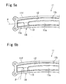
- Figs. 5a and 5b show examples of the packing arrangement when the case 11 is employed, respectively.
- the packing is shown by a chain double-dashed line in Figs. 5a and 5b .
- a packing P extends substantially linearly from one end to the other end in the longitudinal direction of the case across the lower surface of the bottom portion 11a.
- both ends of the packing extending across the lower surface of the bottom portion 11a are directed to the rear of the automobile each at the position before the end of the case 11 (around the drain passage 13) outward (sideward) of the drain passage 13.
- the packing may be provided in the arbitrary arrangement other than the one as described above.
- the drain passages are formed at both left and right ends of the case. However, they may be disposed at the portion other than the one as described above, for example, at an arbitrary position or the intermediate position of the case in the lateral direction.
- the airbag device for pedestrian includes only one airbag. However, it is allowed to have a plurality of airbags.
- the case may be divided into a plurality of chambers.
- the drain passage may be formed in each of the chambers.
- the drain passage may be formed astride the plurality of chambers.
Landscapes
- Engineering & Computer Science (AREA)
- Mechanical Engineering (AREA)
- Chemical & Material Sciences (AREA)
- Combustion & Propulsion (AREA)
- Transportation (AREA)
- Physics & Mathematics (AREA)
- Thermal Sciences (AREA)
- Body Structure For Vehicles (AREA)
- Superstructure Of Vehicle (AREA)
Abstract
Description
- The present invention relates to an airbag device for pedestrian, which is structured to inflate an airbag along an outer surface of an automobile body around a cowl to protect a pedestrian (a pedestrian or a bike rider).
- Generally in an airbag device for pedestrian structured to protect a pedestrian (a pedestrian or a bike rider) by inflating an airbag along the outer surface of the automobile body around the cowl, the airbag stored in a case is disposed around the cowl. A water discharge hole (drain hole) is formed in the bottom of the case to drain water such as rain water intruded into the case (see
Fig. 3 in Japanese Unexamined Patent Application Publication No.2005-178587
[Patent Document 1] Japanese Unexamined Patent Application Publication No.2005-178587 - In the airbag device for pedestrian as disclosed in Japanese Unexamined Patent Application Publication No.
2005-178587 - The present invention provide an airbag device for pedestrian, which is structured to drain water in the case to the cowl.
- The present invention provides an airbag device for pedestrian with an airbag which inflates along an outer surface of an automobile body around a cowl, a case for storing the airbag, and an inflator which inflates the airbag. A drain passage for draining water which has intruded into the case to a cowl is provided.
- The airbag device for pedestrian according to the present invention allows water which has intruded into the case to be drained to the cowl through the drain passage without entering into the engine room. This makes it possible to protect the apparatus and device inside the engine room from being in contact with the drained water from the case.
- The airbag device for pedestrian according to the present invention may be provided with the guide passage for introducing water which has intruded to the front of the case in the region below the hood of the automobile body. In the structure, water which has intruded in the region below the hood to the front of the case may be drained to the cowl via the case and the drain passage, thus preventing the apparatus and device within the engine room from being in contact with the drain water.
-
- [
Fig. 1] Fig. 1 is a perspective view of an automobile equipped with an airbag device for pedestrian according to an embodiment. - [
Fig. 2] Fig. 2 is a perspective view of a case for storing an airbag. - [
Fig. 3] Fig. 3 is a sectional view of the automobile taken along line III-III shown inFig. 2 . - [
Fig. 4] Fig. 4a is a perspective view of the case for storing the airbag of the airbag device for pedestrian according to another example;Fig. 4b is a plan view of the case; andFigs. 4c, 4d, and 4e are sectional views taken along lines C-C, D-D, and E-E shown inFig. 4b , respectively. - [
Fig. 5] Figs. 5a and 5b are plan views each showing an example of an arrangement of a packing for sealing a joint portion between the case and a cowl member. - An embodiment of the present invention will be described referring to the drawings.
Fig. 1 is a perspective view of an automobile equipped with an airbag device for pedestrian according to an example.Fig. 2 is a perspective view of an airbag storage case of the airbag device for pedestrian.Fig. 3 is an enlarged sectional view taken along line III-III shown inFig. 2 . - Referring to
Fig. 1 , an automobile 1 is of a four-door sedan model in the embodiment. However, the present invention is not limited to the vehicle of specific model. An airbag device for pedestrian is installed to the rear portion of ahood 3. As shown in the drawing, when an airbag 5 of the airbag device for pedestrian inflates, a rear edge of thehood 3, acowl louver 2, and at least a portion of a windshield 6 and left andright A pillars 7 are covered with the airbag 5. - The airbag device for pedestrian includes a
case 8 for storing the airbag 5 in the folded state, an inflator (not shown) for inflating the airbag 5, and alid 10 for closing anopening 3a of thehood 3, which allows passage of the airbag. In the embodiment, the inflator is stored in thecase 8 together with the folded airbag 5. - The
case 8 is a long box-like shape extending in a width direction of the automobile. Thecase 8 having an open top surface includes abottom portion 8a, afront wall portion 8b, arear wall portion 8c, and left andright end walls case 8 is disposed at a back side of thehood 3 to allow the open top surface to face theopening 3a, and attached to thehood 3 via a bracket (not shown). - The
case 8 is structured to have the height of the upper surface of thebottom portion 8a lower toward both ends in the lateral direction. Referring toFig. 3 , adrain passage 9 for draining water from inside to outside thecase 8 is formed at both ends of thebottom portion 8a in the lateral direction. Thedrain passage 9 has a descending slope surface toward the rear of the automobile. Each duct-like portion 9a (not shown inFig. 2 ) protrudes at each left and right end of therear wall portion 8c of thecase 8 as an extension of thedrain passage 9 to the rear of the automobile. Adrain hole 9b is formed at the leading end of each of the duct-like portions 9a. - In the embodiment, a
water receiving flange 9c protrudes from thefront wall portion 8b of thecase 8 to the front of the automobile as shown inFig. 3 . Aguide passage 9d communicated from the upper surface of thewater receiving flange 9c to the inside of thecase 8 is formed at the proximal end side of thewater receiving flange 9c. As a result, water which has intruded into the front area of thecase 8 from the opening 3a (water dropped onto theflange 9c, and water which has dropped along the front surface of thefront wall portion 8b) is introduced from theguide passage 9d into thecase 8, and then guided to thedrain passage 9. - The
cowl louver 2 with a gutter-like member extending in the width direction of the automobile body is structured to guide water flowing thereon to the drain section (not shown) at both sides of the automobile body. A long box-like cowl body 2a extending in the width direction of the automobile body is disposed below thecowl louver 2. A wiper device (not shown) is stored in thecowl body 2a. - Referring to
Fig. 3 , thecase 8 is structured to be mounted on afront portion 2b of thecowl louver 2 when closing thehood 3. Areference code 2c denotes a packing for sealing the gap between thecowl louver 2 and thecase 8. - A
lid 10 at the rear edge of the automobile body is hinged (not shown) thereto at the rear edge of the opening 3a of thehood 3 so as to open while turning rearward upon inflation of the airbag 5. The front edge side of thelid 10 is attached to the automobile body at the front edge side of the opening 3a with a fixture member (not shown) such as a clip. The fixture member is structured to release a lock state when thelid 10 is pushed by the airbag 5 and opened. - In the thus structured airbag device for pedestrian, water which has intruded in the
case 8 is drained onto thecowl louver 2 via thedrain passage 9, the duct-like portion 9a and thedrain hole 9b, and accordingly, it is not allowed to enter into the engine room. This makes it possible to prevent the contact between the apparatus and device within the engine room and the drain water. - In the embodiment, water which has intruded into the area below the hood to the front of the
case 8 may be introduced from theguide passage 9d into thecase 8, and drained onto thecowl louver 2 via thedrain passage 9. The contact between the apparatus and device within the engine room and the drain water may be prevented. - The operation of the airbag device for pedestrian will be described hereinafter.
- In the case where a pedestrian is hit by an automobile equipped with the airbag device for pedestrian, the inflator is activated based on the detection signal of a pedestrian collision detection sensor (not shown) installed in the automobile body. The airbag 5 starts inflating by the injected gas. The
lid 10 is pushed by the inflating airbag 5 and then opened such that the airbag 5 deploys along the outer surface of the automobile body as shown inFig. 1 . -
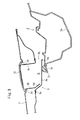
Fig. 4a is a perspective view of the airbag storage case of the airbag device for pedestrian according to another embodiment.Fig. 4b is a plan view of the case.Figs. 4c, 4d and 4e are sectional views taken along lines C-C, D-D, and E-E, respectively shown inFig. 4b . InFigs. 4d and 4e , an arrow direction F denotes the front side of the vehicle, and an arrow direction R denotes the rear side of the vehicle. - An
airbag storage case 11 in the embodiment with a long box-like shape extending in the width (lateral) direction of the automobile includes abottom portion 11a, afront wall portion 11b, arear wall portion 11c, and left andright end walls reference code 11f denotes a flange portion which protrudes from (provided along) the outer surface of thecase 11. An insertion hole (code is omitted) through which the bolt or rivet for fixing thecase 11 to the automobile body is inserted is formed in theflange portion 11f. - Referring to
Fig. 4d , thebottom portion 11a has a descending slope surface toward the front side of the automobile (the arrow F direction). Awater collection groove 12 extending along the longitudinal direction of thecase 11 is formed at the front edge side. Water on thebottom portion 11a drops forward of the automobile so as to be collected in thewater collection groove 12 which extends along substantially the entire length of thecase 11 in the longitudinal direction. - In the example, drain
passages water collection groove 12 outside thecase 11 are formed at positions of thebottom portion 11a apart from the respective ends of thecase 11 in the longitudinal direction toward the center each by a predetermined distance. Referring toFig. 4b , thedrain passage 13 extends from the front to the rear of thecase 11. Thedrain passage 13 at the front end side joins thewater collection groove 12, and the one at the rear end side is communicated with outside thecase 11 via thedrain hole 14 formed in therear wall portion 11c. Referring toFig. 4c , thedrain passage 13 has a descending slope surface toward the rear side (arrow R direction) of the automobile. - As
Fig. 4c shows, each level of thebottom portion 11a and thewater collection groove 12 becomes lower from the center of thecase 11 toward thedrain passage 13, and from both ends of thecase 11 toward thedrain passage 13, respectively. - In the example, the inflator is fixed (not shown) at the portion around the corner where the
bottom portion 11a intersects thefront wall portion 11b. The inflator is arranged higher than thewater collection groove 12 by a predetermined height so as to at least prevent the initiator (ignition device) from being immersed in water. - The other structure of the embodiment is the same as that of the embodiment shown in
Figs. 1 to 3 . - The arrangement of the packing for sealing the joint portion between the case and the cowl member is not limited.
Figs. 5a and 5b show examples of the packing arrangement when thecase 11 is employed, respectively. The packing is shown by a chain double-dashed line inFigs. 5a and 5b . - More specifically, in
Fig. 5a , a packing P extends substantially linearly from one end to the other end in the longitudinal direction of the case across the lower surface of thebottom portion 11a. - Referring to
Fig. 5b , both ends of the packing extending across the lower surface of thebottom portion 11a are directed to the rear of the automobile each at the position before the end of the case 11 (around the drain passage 13) outward (sideward) of thedrain passage 13. - The packing may be provided in the arbitrary arrangement other than the one as described above.
- The respective embodiments show examples of the present invention, and are not limited thereto.
- In the aforementioned embodiments, the drain passages (drain holes) are formed at both left and right ends of the case. However, they may be disposed at the portion other than the one as described above, for example, at an arbitrary position or the intermediate position of the case in the lateral direction.
- The airbag device for pedestrian according to the embodiments includes only one airbag. However, it is allowed to have a plurality of airbags.
- The case may be divided into a plurality of chambers. In this case, the drain passage may be formed in each of the chambers. Alternatively, the drain passage may be formed astride the plurality of chambers.
- The present invention has been described in accordance with the specific example. It is to be understood that the present invention may be changed or modified into various forms without departing from the scope of the present invention.
The present invention is based on the disclosure of Japanese Patent Application No.2006-16322 filed on January 25, 2006
Claims (5)
- An airbag device for pedestrian with an airbag which inflates along an outer surface of an automobile body around a cowl, a case for storing the airbag, and an inflator which inflates the airbag, wherein a drain passage for draining water which has intruded into the case to a cowl is provided.
- The airbag device for pedestrian according to Claim 1, further comprising a guide passage for introducing water which has intruded to a front side of the case in a region below a hood of the automobile body into the case.
- The airbag device for pedestrian according to Claim 1, wherein the case has a long box-like shape extending in a width direction of the automobile body and an open top surface, and includes a bottom portion, a front wall portion, a rear wall portion, and left and right end walls.
- The airbag device for pedestrian according to Claim 3, wherein:the case installed in the automobile body is structured to have the top surface of the bottom portion lowered toward each end of the automobile body in a lateral direction; andthe drain passages are formed at both ends of the bottom portion in the lateral direction.
- The airbag device for pedestrian according to Claim 3, wherein:a water collection groove is formed in a bottom surface of the case to extend in a longitudinal direction of the case; andthe drain passage is communicated with the water collection groove.
Applications Claiming Priority (2)
| Application Number | Priority Date | Filing Date | Title |
|---|---|---|---|
| JP2006016322A JP2007196787A (en) | 2006-01-25 | 2006-01-25 | Pedestrian airbag device |
| PCT/JP2007/050081 WO2007086246A1 (en) | 2006-01-25 | 2007-01-09 | Pedestrian airbag device |
Publications (3)
| Publication Number | Publication Date |
|---|---|
| EP1977937A1 true EP1977937A1 (en) | 2008-10-08 |
| EP1977937A4 EP1977937A4 (en) | 2009-04-22 |
| EP1977937B1 EP1977937B1 (en) | 2013-08-07 |
Family
ID=38309045
Family Applications (1)
| Application Number | Title | Priority Date | Filing Date |
|---|---|---|---|
| EP07706428.5A Ceased EP1977937B1 (en) | 2006-01-25 | 2007-01-09 | Vehicle comprising a pedestrian airbag device |
Country Status (5)
| Country | Link |
|---|---|
| US (1) | US7770684B2 (en) |
| EP (1) | EP1977937B1 (en) |
| JP (1) | JP2007196787A (en) |
| CN (1) | CN101374704B (en) |
| WO (1) | WO2007086246A1 (en) |
Cited By (3)
| Publication number | Priority date | Publication date | Assignee | Title |
|---|---|---|---|---|
| EP2796327A3 (en) * | 2013-04-26 | 2014-11-12 | Takata Corporation | Airbag unit and airbag folding method |
| WO2014139937A3 (en) * | 2013-03-11 | 2014-11-13 | Takata AG | Airbag module assembly for a motor vehicle |
| EP3109099A4 (en) * | 2014-02-19 | 2017-09-27 | Subaru Corporation | Airbag apparatus |
Families Citing this family (14)
| Publication number | Priority date | Publication date | Assignee | Title |
|---|---|---|---|---|
| JP2009056991A (en) * | 2007-09-03 | 2009-03-19 | Takata Corp | Seatbelt retractor and seatbelt device having the same |
| US20100300792A1 (en) * | 2009-05-28 | 2010-12-02 | Liang-Yann Yuan | Airbag apparatus for pedestrian protection |
| DE102009023779A1 (en) * | 2009-06-03 | 2010-12-09 | GM Global Technology Operations, Inc., Detroit | Motor vehicle with windscreen airbag |
| JP5601018B2 (en) * | 2010-05-18 | 2014-10-08 | スズキ株式会社 | Vehicle cowl structure |
| JP5580114B2 (en) * | 2010-05-31 | 2014-08-27 | アスモ株式会社 | Wiper blade |
| JP5900378B2 (en) * | 2013-03-01 | 2016-04-06 | マツダ株式会社 | Front body structure of the vehicle |
| GB2516699B (en) * | 2013-07-30 | 2017-05-03 | Jaguar Land Rover Ltd | Airbag device for a vehicle bonnet |
| KR101526751B1 (en) * | 2013-12-18 | 2015-06-05 | 현대자동차주식회사 | Pedestrian air-bag for vehicle |
| JP6301151B2 (en) * | 2014-02-19 | 2018-03-28 | 株式会社Subaru | Airbag device |
| JP6447031B2 (en) * | 2014-11-11 | 2019-01-09 | Joyson Safety Systems Japan株式会社 | Pedestrian airbag device |
| DE102016004110A1 (en) * | 2016-04-05 | 2017-10-05 | GM Global Technology Operations LLC (n. d. Ges. d. Staates Delaware) | Motor vehicle with pedestrian airbag |
| CN106428223B (en) * | 2016-11-09 | 2018-09-28 | 山东国金汽车制造有限公司 | A kind of novel front wall vent flap |
| JP6919613B2 (en) * | 2018-03-28 | 2021-08-18 | 豊田合成株式会社 | Airbag device |
| JP7290613B2 (en) * | 2020-08-25 | 2023-06-13 | トヨタ自動車株式会社 | vehicle |
Family Cites Families (16)
| Publication number | Priority date | Publication date | Assignee | Title |
|---|---|---|---|---|
| JPS5660686U (en) * | 1979-10-16 | 1981-05-23 | ||
| JP3245489B2 (en) | 1993-10-29 | 2002-01-15 | トヨタ自動車株式会社 | Waterproof structure of food airbag device |
| JP3791379B2 (en) * | 2001-10-02 | 2006-06-28 | トヨタ自動車株式会社 | Hood airbag device |
| JP3969121B2 (en) * | 2002-02-26 | 2007-09-05 | 豊田合成株式会社 | Pedestrian protection device |
| US6923286B2 (en) * | 2002-02-26 | 2005-08-02 | Toyoda Gosei Co., Ltd. | Pedestrian protecting device |
| JP3951747B2 (en) * | 2002-03-01 | 2007-08-01 | タカタ株式会社 | Externally deployable airbag device |
| JP4308643B2 (en) | 2003-12-19 | 2009-08-05 | 芦森工業株式会社 | Pedestrian airbag device |
| JP4238755B2 (en) * | 2004-03-17 | 2009-03-18 | 豊田合成株式会社 | Food panel |
| US7243754B2 (en) * | 2004-03-17 | 2007-07-17 | Toyoda Gosei Co., Ltd. | Pedestrian airbag system |
| JP2005349954A (en) * | 2004-06-10 | 2005-12-22 | Toyoda Gosei Co Ltd | Air bag device for pedestrian |
| US7404597B2 (en) * | 2004-06-29 | 2008-07-29 | Honda Motor Co., Ltd. | Sunroof drain tube mounting arrangement |
| JP2006016322A (en) | 2004-06-30 | 2006-01-19 | Mitsubishi Rayon Co Ltd | Method for removing tin compounds |
| JP4639129B2 (en) * | 2005-09-07 | 2011-02-23 | タカタ株式会社 | Airbag device, motorcycle with airbag device |
| JP4683388B2 (en) * | 2005-09-07 | 2011-05-18 | タカタ株式会社 | Airbag device, motorcycle with airbag device |
| JP4684077B2 (en) * | 2005-10-17 | 2011-05-18 | タカタ株式会社 | Airbag device, motorcycle with airbag device |
| JP5050356B2 (en) * | 2006-01-25 | 2012-10-17 | タカタ株式会社 | Pedestrian airbag device |
-
2006
- 2006-01-25 JP JP2006016322A patent/JP2007196787A/en active Pending
-
2007
- 2007-01-09 CN CN2007800035564A patent/CN101374704B/en not_active Expired - Fee Related
- 2007-01-09 EP EP07706428.5A patent/EP1977937B1/en not_active Ceased
- 2007-01-09 WO PCT/JP2007/050081 patent/WO2007086246A1/en not_active Ceased
- 2007-01-09 US US12/087,570 patent/US7770684B2/en not_active Expired - Fee Related
Non-Patent Citations (2)
| Title |
|---|
| No further relevant documents disclosed * |
| See also references of WO2007086246A1 * |
Cited By (4)
| Publication number | Priority date | Publication date | Assignee | Title |
|---|---|---|---|---|
| WO2014139937A3 (en) * | 2013-03-11 | 2014-11-13 | Takata AG | Airbag module assembly for a motor vehicle |
| EP2796327A3 (en) * | 2013-04-26 | 2014-11-12 | Takata Corporation | Airbag unit and airbag folding method |
| US9346432B2 (en) | 2013-04-26 | 2016-05-24 | Takata Corporation | Airbag unit and airbag folding method |
| EP3109099A4 (en) * | 2014-02-19 | 2017-09-27 | Subaru Corporation | Airbag apparatus |
Also Published As
| Publication number | Publication date |
|---|---|
| CN101374704B (en) | 2010-12-08 |
| WO2007086246A1 (en) | 2007-08-02 |
| JP2007196787A (en) | 2007-08-09 |
| CN101374704A (en) | 2009-02-25 |
| US7770684B2 (en) | 2010-08-10 |
| EP1977937A4 (en) | 2009-04-22 |
| EP1977937B1 (en) | 2013-08-07 |
| US20080314672A1 (en) | 2008-12-25 |
Similar Documents
| Publication | Publication Date | Title |
|---|---|---|
| EP1977937B1 (en) | Vehicle comprising a pedestrian airbag device | |
| US7174985B2 (en) | Exterior airbag device | |
| US7549663B2 (en) | Airbag device for pedestrian | |
| US20040232663A1 (en) | Externally developed airbag device | |
| EP0904992A2 (en) | Placement structure for head-protecting air bag body | |
| EP1700758A1 (en) | Airbag and airbag device for protecting a pedestrian or the like | |
| EP1681212A2 (en) | Protection apparatus for pedestrian or the like and airbag therefor | |
| JP4951986B2 (en) | Air bag and air bag device | |
| EP1976729B1 (en) | Airbag apparatus | |
| US7712767B2 (en) | Airbag device | |
| US7828319B2 (en) | Airbag for pedestrian and airbag apparatus for pedestrian | |
| EP1937518B1 (en) | Hood airbag device | |
| EP1527966A1 (en) | Protection device for pedestrian or the like | |
| JP4656031B2 (en) | Drainage structure for vehicle and drainage structure of vehicle hood airbag device using the same | |
| JP2005262954A (en) | Hood panel | |
| JP2005343199A (en) | Air bag device for pedestrian | |
| JP2007196801A (en) | Seal structure of vehicle hood airbag device |
Legal Events
| Date | Code | Title | Description |
|---|---|---|---|
| PUAI | Public reference made under article 153(3) epc to a published international application that has entered the european phase |
Free format text: ORIGINAL CODE: 0009012 |
|
| 17P | Request for examination filed |
Effective date: 20080808 |
|
| AK | Designated contracting states |
Kind code of ref document: A1 Designated state(s): DE GB |
|
| R17P | Request for examination filed (corrected) |
Effective date: 20080813 |
|
| RBV | Designated contracting states (corrected) |
Designated state(s): DE GB |
|
| RBV | Designated contracting states (corrected) |
Designated state(s): DE GB |
|
| A4 | Supplementary search report drawn up and despatched |
Effective date: 20090319 |
|
| 17Q | First examination report despatched |
Effective date: 20090720 |
|
| DAX | Request for extension of the european patent (deleted) | ||
| REG | Reference to a national code |
Ref country code: DE Ref legal event code: R079 Ref document number: 602007032105 Country of ref document: DE Free format text: PREVIOUS MAIN CLASS: B60R0021340000 Ipc: B60R0021360000 |
|
| GRAP | Despatch of communication of intention to grant a patent |
Free format text: ORIGINAL CODE: EPIDOSNIGR1 |
|
| RIC1 | Information provided on ipc code assigned before grant |
Ipc: B62D 25/08 20060101ALI20130129BHEP Ipc: B60R 21/36 20110101AFI20130129BHEP |
|
| GRAS | Grant fee paid |
Free format text: ORIGINAL CODE: EPIDOSNIGR3 |
|
| GRAA | (expected) grant |
Free format text: ORIGINAL CODE: 0009210 |
|
| AK | Designated contracting states |
Kind code of ref document: B1 Designated state(s): DE GB |
|
| REG | Reference to a national code |
Ref country code: GB Ref legal event code: FG4D |
|
| REG | Reference to a national code |
Ref country code: DE Ref legal event code: R096 Ref document number: 602007032105 Country of ref document: DE Effective date: 20131002 |
|
| PGFP | Annual fee paid to national office [announced via postgrant information from national office to epo] |
Ref country code: DE Payment date: 20140228 Year of fee payment: 8 |
|
| PLBE | No opposition filed within time limit |
Free format text: ORIGINAL CODE: 0009261 |
|
| STAA | Information on the status of an ep patent application or granted ep patent |
Free format text: STATUS: NO OPPOSITION FILED WITHIN TIME LIMIT |
|
| 26N | No opposition filed |
Effective date: 20140508 |
|
| REG | Reference to a national code |
Ref country code: DE Ref legal event code: R097 Ref document number: 602007032105 Country of ref document: DE Effective date: 20140508 |
|
| GBPC | Gb: european patent ceased through non-payment of renewal fee |
Effective date: 20140109 |
|
| PG25 | Lapsed in a contracting state [announced via postgrant information from national office to epo] |
Ref country code: GB Free format text: LAPSE BECAUSE OF NON-PAYMENT OF DUE FEES Effective date: 20140109 |
|
| REG | Reference to a national code |
Ref country code: DE Ref legal event code: R119 Ref document number: 602007032105 Country of ref document: DE |
|
| PG25 | Lapsed in a contracting state [announced via postgrant information from national office to epo] |
Ref country code: DE Free format text: LAPSE BECAUSE OF NON-PAYMENT OF DUE FEES Effective date: 20150801 |