EP1977720A1 - Dome shaped implant and inserter - Google Patents
Dome shaped implant and inserter Download PDFInfo
- Publication number
- EP1977720A1 EP1977720A1 EP08450051A EP08450051A EP1977720A1 EP 1977720 A1 EP1977720 A1 EP 1977720A1 EP 08450051 A EP08450051 A EP 08450051A EP 08450051 A EP08450051 A EP 08450051A EP 1977720 A1 EP1977720 A1 EP 1977720A1
- Authority
- EP
- European Patent Office
- Prior art keywords
- implant
- inserter
- assembly
- head
- arms
- Prior art date
- Legal status (The legal status is an assumption and is not a legal conclusion. Google has not performed a legal analysis and makes no representation as to the accuracy of the status listed.)
- Granted
Links
Images



Classifications
-
- A—HUMAN NECESSITIES
- A61—MEDICAL OR VETERINARY SCIENCE; HYGIENE
- A61F—FILTERS IMPLANTABLE INTO BLOOD VESSELS; PROSTHESES; DEVICES PROVIDING PATENCY TO, OR PREVENTING COLLAPSING OF, TUBULAR STRUCTURES OF THE BODY, e.g. STENTS; ORTHOPAEDIC, NURSING OR CONTRACEPTIVE DEVICES; FOMENTATION; TREATMENT OR PROTECTION OF EYES OR EARS; BANDAGES, DRESSINGS OR ABSORBENT PADS; FIRST-AID KITS
- A61F2/00—Filters implantable into blood vessels; Prostheses, i.e. artificial substitutes or replacements for parts of the body; Appliances for connecting them with the body; Devices providing patency to, or preventing collapsing of, tubular structures of the body, e.g. stents
- A61F2/02—Prostheses implantable into the body
- A61F2/30—Joints
- A61F2/38—Joints for elbows or knees
- A61F2/3877—Patellae or trochleae
-
- A—HUMAN NECESSITIES
- A61—MEDICAL OR VETERINARY SCIENCE; HYGIENE
- A61F—FILTERS IMPLANTABLE INTO BLOOD VESSELS; PROSTHESES; DEVICES PROVIDING PATENCY TO, OR PREVENTING COLLAPSING OF, TUBULAR STRUCTURES OF THE BODY, e.g. STENTS; ORTHOPAEDIC, NURSING OR CONTRACEPTIVE DEVICES; FOMENTATION; TREATMENT OR PROTECTION OF EYES OR EARS; BANDAGES, DRESSINGS OR ABSORBENT PADS; FIRST-AID KITS
- A61F2/00—Filters implantable into blood vessels; Prostheses, i.e. artificial substitutes or replacements for parts of the body; Appliances for connecting them with the body; Devices providing patency to, or preventing collapsing of, tubular structures of the body, e.g. stents
- A61F2/02—Prostheses implantable into the body
- A61F2/30—Joints
- A61F2/40—Joints for shoulders
-
- A—HUMAN NECESSITIES
- A61—MEDICAL OR VETERINARY SCIENCE; HYGIENE
- A61F—FILTERS IMPLANTABLE INTO BLOOD VESSELS; PROSTHESES; DEVICES PROVIDING PATENCY TO, OR PREVENTING COLLAPSING OF, TUBULAR STRUCTURES OF THE BODY, e.g. STENTS; ORTHOPAEDIC, NURSING OR CONTRACEPTIVE DEVICES; FOMENTATION; TREATMENT OR PROTECTION OF EYES OR EARS; BANDAGES, DRESSINGS OR ABSORBENT PADS; FIRST-AID KITS
- A61F2/00—Filters implantable into blood vessels; Prostheses, i.e. artificial substitutes or replacements for parts of the body; Appliances for connecting them with the body; Devices providing patency to, or preventing collapsing of, tubular structures of the body, e.g. stents
- A61F2/02—Prostheses implantable into the body
- A61F2/30—Joints
- A61F2/46—Special tools for implanting artificial joints
- A61F2/4603—Special tools for implanting artificial joints for insertion or extraction of endoprosthetic joints or of accessories thereof
- A61F2/461—Special tools for implanting artificial joints for insertion or extraction of endoprosthetic joints or of accessories thereof of knees
-
- A—HUMAN NECESSITIES
- A61—MEDICAL OR VETERINARY SCIENCE; HYGIENE
- A61F—FILTERS IMPLANTABLE INTO BLOOD VESSELS; PROSTHESES; DEVICES PROVIDING PATENCY TO, OR PREVENTING COLLAPSING OF, TUBULAR STRUCTURES OF THE BODY, e.g. STENTS; ORTHOPAEDIC, NURSING OR CONTRACEPTIVE DEVICES; FOMENTATION; TREATMENT OR PROTECTION OF EYES OR EARS; BANDAGES, DRESSINGS OR ABSORBENT PADS; FIRST-AID KITS
- A61F2/00—Filters implantable into blood vessels; Prostheses, i.e. artificial substitutes or replacements for parts of the body; Appliances for connecting them with the body; Devices providing patency to, or preventing collapsing of, tubular structures of the body, e.g. stents
- A61F2/02—Prostheses implantable into the body
- A61F2/30—Joints
- A61F2/46—Special tools for implanting artificial joints
- A61F2/4603—Special tools for implanting artificial joints for insertion or extraction of endoprosthetic joints or of accessories thereof
- A61F2/4612—Special tools for implanting artificial joints for insertion or extraction of endoprosthetic joints or of accessories thereof of shoulders
-
- A—HUMAN NECESSITIES
- A61—MEDICAL OR VETERINARY SCIENCE; HYGIENE
- A61F—FILTERS IMPLANTABLE INTO BLOOD VESSELS; PROSTHESES; DEVICES PROVIDING PATENCY TO, OR PREVENTING COLLAPSING OF, TUBULAR STRUCTURES OF THE BODY, e.g. STENTS; ORTHOPAEDIC, NURSING OR CONTRACEPTIVE DEVICES; FOMENTATION; TREATMENT OR PROTECTION OF EYES OR EARS; BANDAGES, DRESSINGS OR ABSORBENT PADS; FIRST-AID KITS
- A61F2/00—Filters implantable into blood vessels; Prostheses, i.e. artificial substitutes or replacements for parts of the body; Appliances for connecting them with the body; Devices providing patency to, or preventing collapsing of, tubular structures of the body, e.g. stents
- A61F2/02—Prostheses implantable into the body
- A61F2/30—Joints
- A61F2/42—Joints for wrists or ankles; for hands, e.g. fingers; for feet, e.g. toes
-
- A—HUMAN NECESSITIES
- A61—MEDICAL OR VETERINARY SCIENCE; HYGIENE
- A61F—FILTERS IMPLANTABLE INTO BLOOD VESSELS; PROSTHESES; DEVICES PROVIDING PATENCY TO, OR PREVENTING COLLAPSING OF, TUBULAR STRUCTURES OF THE BODY, e.g. STENTS; ORTHOPAEDIC, NURSING OR CONTRACEPTIVE DEVICES; FOMENTATION; TREATMENT OR PROTECTION OF EYES OR EARS; BANDAGES, DRESSINGS OR ABSORBENT PADS; FIRST-AID KITS
- A61F2/00—Filters implantable into blood vessels; Prostheses, i.e. artificial substitutes or replacements for parts of the body; Appliances for connecting them with the body; Devices providing patency to, or preventing collapsing of, tubular structures of the body, e.g. stents
- A61F2/02—Prostheses implantable into the body
- A61F2/30—Joints
- A61F2/46—Special tools for implanting artificial joints
- A61F2/4603—Special tools for implanting artificial joints for insertion or extraction of endoprosthetic joints or of accessories thereof
- A61F2/4606—Special tools for implanting artificial joints for insertion or extraction of endoprosthetic joints or of accessories thereof of wrists or ankles; of hands, e.g. fingers; of feet, e.g. toes
-
- A—HUMAN NECESSITIES
- A61—MEDICAL OR VETERINARY SCIENCE; HYGIENE
- A61F—FILTERS IMPLANTABLE INTO BLOOD VESSELS; PROSTHESES; DEVICES PROVIDING PATENCY TO, OR PREVENTING COLLAPSING OF, TUBULAR STRUCTURES OF THE BODY, e.g. STENTS; ORTHOPAEDIC, NURSING OR CONTRACEPTIVE DEVICES; FOMENTATION; TREATMENT OR PROTECTION OF EYES OR EARS; BANDAGES, DRESSINGS OR ABSORBENT PADS; FIRST-AID KITS
- A61F2/00—Filters implantable into blood vessels; Prostheses, i.e. artificial substitutes or replacements for parts of the body; Appliances for connecting them with the body; Devices providing patency to, or preventing collapsing of, tubular structures of the body, e.g. stents
- A61F2/02—Prostheses implantable into the body
- A61F2/30—Joints
- A61F2/46—Special tools for implanting artificial joints
- A61F2/4603—Special tools for implanting artificial joints for insertion or extraction of endoprosthetic joints or of accessories thereof
- A61F2002/4625—Special tools for implanting artificial joints for insertion or extraction of endoprosthetic joints or of accessories thereof with relative movement between parts of the instrument during use
- A61F2002/4628—Special tools for implanting artificial joints for insertion or extraction of endoprosthetic joints or of accessories thereof with relative movement between parts of the instrument during use with linear motion along or rotating motion about an axis transverse to the instrument axis or to the implantation direction, e.g. clamping
Definitions
- the present invention relates to a dome shaped implant for joint resurfacing and an inserter for the implant.
- the present invention provides an implant/inserter assembly designed to facilitate the handling and subsequent insertion of an implant at a surgical site.
- the inserter is provided with a plurality of arms that securely engage a plurality of indents on the edge or periphery of the implant.
- FIG. 1 illustrates a perspective view of an implant/inserter assembly of the present invention, in a detached state
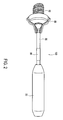
- FIG. 2 illustrates a perspective view of an implant/inserter assembly of the present invention, in an attached state
- FIG. 3 is a schematic view of the implant/inserter assembly of the present invention.
- FIGS. 4(a)-(c) illustrate additional perspective views the implant/inserter assembly of the present invention
- FIG. 5 is a perspective view of the implant of the present invention.
- FIG. 6 is a front view of the implant of the present invention.
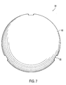
- FIG. 7 is a top view of the implant of the present invention.
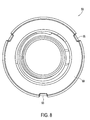
- FIG. 8 is a bottom view of the implant of the present invention.
- the present invention provides a dome shaped implant and an inserter that is configured to allow improved handling of the implant within a joint capsule, for example the knee capsule or the shoulder joint, during surgical reconstruction.
- the implant of the present invention is designed to be securely engaged by a corresponding inserter or driver.
- the implant is preferably provided with a dome or eclipse-like head having a plurality of indents on the periphery of the head.
- the plurality of indents are configured to be engaged by arms (tabs) of a corresponding inserter instrument.
- the present invention also provides an inserter designed to increase the handling and subsequent insertion of the implant at a surgical site.
- the inserter is provided with a plurality of arms that securely engage a plurality of indents on the edge or periphery of the implant.
- the arms of the inserter attach to the implant by sliding back the shaft of the inserter.
- the arms of the inserter detach from the implant by sliding the shaft forward (with open arms).
- FIGS. 1-8 illustrate various components of an implant/inserter assembly 100 of the present invention.
- the implant/inserter assembly 100 allows improved handling of the implant within a joint capsule, for example the knee capsule or the shoulder joint, during surgical reconstruction.
- implant/inserter assembly 100 comprises an implant or implant screw 50 designed to be securely engaged by an inserter or driver 80.
- Figure 1 illustrates the detached configuration of the implant/inserter assembly 100 (i.e., implant 50 detached from inserter 80).
- Figures 2-4 illustrate the attached configuration of the implant/inserter assembly 100 (i.e., implant 50 engaged by inserter 80).
- the implant screw 50 is preferably formed of titanium or titanium alloy materials, for example, or other biomedically acceptable materials.
- the implant screw 50 can be formed of a bioabsorbable, biocompatible material, such as Resomer L210 Poly (L-Lactide) acid (PLLA) or an equivalent material.
- PLLA Resomer L210 Poly (L-Lactide) acid
- a dome shaped implant formed of PLLA material provides the advantages of not being visible on radiographs and not interfering with MRI or CT scans.
- implant 50 is provided with a body 52 and a dome or eclipse-like head 60.
- Body 52 may be provided with a continuous thread 54 (as shown in the drawings) and may have a cylindrical configuration with a blunt end at its distal end 56.
- body 52 may be partially threaded.
- body 52 may be also provided with a plurality of fenestrations 53, to allow tissue in-growth.
- the proximal face of the head 60 has at least one opening or indent 55 ( Figures 5-8 ) for engaging an inserter or driver.
- the preferred embodiment of the invention has three equally spaced openings or arcuate slots 55 formed in the dome-shaped head to engage the driver/inserter used for delivery and installation of the implant, as described below.
- the plurality of indents or slots 55 are provided on the periphery or edge of the head 60.
- the plurality of indents or slots 55 may have various configurations and geometries, for example, a rectangular shape as illustrated in Figures 5-8 .
- indents 55 may have any configuration that allows them to be engaged by arms (or tabs) 88 ( Figures 1-3 ) of the corresponding inserter instrument 80.
- Slots 55 are positioned on the edge of head 60 so that the depth of slots 55 can extend slightly below the depth of head 60. In this manner, slots 55 enable solid coupling between an engaged inserter/driver and the screw for inserting/driving the screw.
- inserter 80 is preferably provided with handle 85, shaft 86 and plurality of arms 88. Arms 88 may be provided in any number and configuration to allow to securably engage indents 55 on the periphery or edge of the implant 50.
- the arms 88 of the inserter 80 attach to the indents or slots 55 of the implant 50 by sliding back shaft 86 of the inserter 80.
- the arms 88 of the inserter 80 detach from the indents or slots 55 of the implant 50 by sliding shaft 86 forward (with open arms). Engagement and/or disengagement of the arms 88 with/from the indents 55 may be facilitated by actuating an actuating mechanism (for example, a knurl or a ring feature) provided on, or in communication with, the handle 85 of the inserter 80.
- an actuating mechanism for example, a knurl or a ring feature
- the present invention also provides a method of conducting arthroscopic surgery by: (i) forming a socket at a surgical repair site; (ii) providing the implant/inserter assembly 100 of the present invention in the vicinity of the surgical repair site; and (iii) securing the implant at least partially (preferably fully) within the socket.
- the implant screw and driver assembly of the present invention are designed to be used to insert a dome shaped implant within a joint capsule, for example, the knee capsule or the shoulder joint, to resurface the load bearing surface of the joint.
- a joint capsule for example, the knee capsule or the shoulder joint
- the present invention has a variety of possible uses and applications relating to screw insertion, not necessarily limited to joint surgery or to orthopedics.
Landscapes
- Health & Medical Sciences (AREA)
- Orthopedic Medicine & Surgery (AREA)
- Transplantation (AREA)
- Heart & Thoracic Surgery (AREA)
- Life Sciences & Earth Sciences (AREA)
- Cardiology (AREA)
- Engineering & Computer Science (AREA)
- Biomedical Technology (AREA)
- Veterinary Medicine (AREA)
- Vascular Medicine (AREA)
- Oral & Maxillofacial Surgery (AREA)
- Animal Behavior & Ethology (AREA)
- General Health & Medical Sciences (AREA)
- Public Health (AREA)
- Physical Education & Sports Medicine (AREA)
- Prostheses (AREA)
- Surgical Instruments (AREA)
Abstract
Description
- The present invention relates to a dome shaped implant for joint resurfacing and an inserter for the implant.
- When a bearing surface of a joint becomes damaged, one solution is to replace the damaged surface with an implant having a hemispherical surface that matches the contour of the damaged cartilage of the joint. Insertion of these implants, is typically problematic as it is difficult to handle such fixation devices within the joint capsule (during arthroscopic surgery, for example) where visibility and access to the structures of the joint is minimal. It is also difficult to precisely position such fixation devices at the arthroscopic site.
- Accordingly, a need exists for a surgical implant and inserter that is configured to facilitate handling of the implant within a joint capsule, for example the knee capsule or the shoulder joint, during surgical reconstruction. A need also exists for a surgical implant and inserter that is stable during surgery and that allows for precise positioning of the implant during insertion and fixation.
- The present invention provides an implant/inserter assembly designed to facilitate the handling and subsequent insertion of an implant at a surgical site. The inserter is provided with a plurality of arms that securely engage a plurality of indents on the edge or periphery of the implant.
- These and other features and advantages of the invention will be more apparent from the following detailed description that is provided in connection with the accompanying drawings and illustrated exemplary embodiments of the invention.
-
FIG. 1 illustrates a perspective view of an implant/inserter assembly of the present invention, in a detached state; -
FIG. 2 illustrates a perspective view of an implant/inserter assembly of the present invention, in an attached state; -
FIG. 3 is a schematic view of the implant/inserter assembly of the present invention; -
FIGS. 4(a)-(c) illustrate additional perspective views the implant/inserter assembly of the present invention; -
FIG. 5 is a perspective view of the implant of the present invention; -
FIG. 6 is a front view of the implant of the present invention; -
FIG. 7 is a top view of the implant of the present invention; and -
FIG. 8 is a bottom view of the implant of the present invention. - In the following detailed description, reference is made to various specific embodiments in which the invention may be practiced. These embodiments are described with sufficient detail to enable those skilled in the art to practice the invention, and it is to be understood that other embodiments may be employed, and that structural and logical changes may be made without departing from the spirit or scope of the present invention.
- The present invention provides a dome shaped implant and an inserter that is configured to allow improved handling of the implant within a joint capsule, for example the knee capsule or the shoulder joint, during surgical reconstruction.
- The implant of the present invention is designed to be securely engaged by a corresponding inserter or driver. The implant is preferably provided with a dome or eclipse-like head having a plurality of indents on the periphery of the head. The plurality of indents are configured to be engaged by arms (tabs) of a corresponding inserter instrument.
- The present invention also provides an inserter designed to increase the handling and subsequent insertion of the implant at a surgical site. The inserter is provided with a plurality of arms that securely engage a plurality of indents on the edge or periphery of the implant. In an exemplary embodiment, the arms of the inserter attach to the implant by sliding back the shaft of the inserter. Alternatively, the arms of the inserter detach from the implant by sliding the shaft forward (with open arms).
- Referring now to the drawings, where like elements are designated by like reference numerals,
Figures 1-8 illustrate various components of an implant/inserter assembly 100 of the present invention. The implant/inserter assembly 100 allows improved handling of the implant within a joint capsule, for example the knee capsule or the shoulder joint, during surgical reconstruction. - As shown in the drawings, implant/
inserter assembly 100 comprises an implant orimplant screw 50 designed to be securely engaged by an inserter ordriver 80.Figure 1 illustrates the detached configuration of the implant/inserter assembly 100 (i.e.,implant 50 detached from inserter 80).Figures 2-4 illustrate the attached configuration of the implant/inserter assembly 100 (i.e., implant 50 engaged by inserter 80). - The
implant screw 50 is preferably formed of titanium or titanium alloy materials, for example, or other biomedically acceptable materials. Alternatively, theimplant screw 50 can be formed of a bioabsorbable, biocompatible material, such as Resomer L210 Poly (L-Lactide) acid (PLLA) or an equivalent material. In addition to being biocompatible and bioabsorbable, a dome shaped implant formed of PLLA material provides the advantages of not being visible on radiographs and not interfering with MRI or CT scans. - In a preferred embodiment, and as illustrated in
Figures 5-8 ,implant 50 is provided with abody 52 and a dome or eclipse-like head 60.Body 52 may be provided with a continuous thread 54 (as shown in the drawings) and may have a cylindrical configuration with a blunt end at its distal end 56. In exemplary embodiments,body 52 may be partially threaded. As shown inFigures 5 and6 , for example,body 52 may be also provided with a plurality offenestrations 53, to allow tissue in-growth. - The proximal face of the
head 60 has at least one opening or indent 55 (Figures 5-8 ) for engaging an inserter or driver. Although many different drive coupling arrangements are possible, the preferred embodiment of the invention has three equally spaced openings orarcuate slots 55 formed in the dome-shaped head to engage the driver/inserter used for delivery and installation of the implant, as described below. Preferably, the plurality of indents orslots 55 are provided on the periphery or edge of thehead 60. The plurality of indents orslots 55 may have various configurations and geometries, for example, a rectangular shape as illustrated inFigures 5-8 . However,indents 55 may have any configuration that allows them to be engaged by arms (or tabs) 88 (Figures 1-3 ) of thecorresponding inserter instrument 80.Slots 55 are positioned on the edge ofhead 60 so that the depth ofslots 55 can extend slightly below the depth ofhead 60. In this manner,slots 55 enable solid coupling between an engaged inserter/driver and the screw for inserting/driving the screw. - As also illustrated in
Figures 1-4 ,inserter 80 is preferably provided withhandle 85,shaft 86 and plurality ofarms 88.Arms 88 may be provided in any number and configuration to allow to securably engageindents 55 on the periphery or edge of theimplant 50. - In use, and according to an exemplary embodiment only, the
arms 88 of theinserter 80 attach to the indents orslots 55 of theimplant 50 by slidingback shaft 86 of theinserter 80. Alternatively, thearms 88 of theinserter 80 detach from the indents orslots 55 of theimplant 50 by slidingshaft 86 forward (with open arms). Engagement and/or disengagement of thearms 88 with/from theindents 55 may be facilitated by actuating an actuating mechanism (for example, a knurl or a ring feature) provided on, or in communication with, thehandle 85 of theinserter 80. - The present invention also provides a method of conducting arthroscopic surgery by: (i) forming a socket at a surgical repair site; (ii) providing the implant/
inserter assembly 100 of the present invention in the vicinity of the surgical repair site; and (iii) securing the implant at least partially (preferably fully) within the socket. - The implant screw and driver assembly of the present invention are designed to be used to insert a dome shaped implant within a joint capsule, for example, the knee capsule or the shoulder joint, to resurface the load bearing surface of the joint. However, it will be apparent to those skilled in the art that the present invention has a variety of possible uses and applications relating to screw insertion, not necessarily limited to joint surgery or to orthopedics.
- The above description and drawings illustrate preferred embodiments which achieve the objects, features and advantages of the present invention. It is not intended that the present invention be limited to the illustrated embodiments. Any modification of the present invention which comes within the spirit and scope of the following claims should be considered part of the present invention.
Claims (11)
- An implant and inserter assembly, comprising:a screw comprising a distal end, a body portion of a first diameter and a proximal end, wherein the proximal end is provided with a head of a second diameter, and wherein the head is provided with a plurality of indents disposed on an outer surface of the head; andan inserter comprising a handle, a shaft, and a plurality of arms configured to securely engage the plurality of indents on the outer surface of the head.
- The assembly of claim 1, wherein at least a portion of the body portion is threaded.
- The assembly of claim 1, wherein the proximal end is integrally attached to the head.
- The assembly of claim 1, wherein the plurality of arms extend in a direction about parallel to a longitudinal axis of the shaft.
- The assembly of claim 1, wherein the plurality of indents have a rectangular shape.
- The assembly of claim 1, wherein the plurality of arms are configured to disengage the plurality of indents on the outer surface of the head, when the implant is at least partially secured within a socket at a surgical site.
- The assembly of claim 6, wherein the inserter further comprises an actuating mechanism provided adjacent the shaft and in communication with the plurality of arms for moving the arms into one of an open position and a close position.
- The assembly of claim 7, wherein the actuating mechanism is a knurl or a ring configured to slide back or forth the shaft of the inserter.
- The assembly of claim 1, wherein the head of the screw has an dome-shaped configuration.
- The assembly of claim 1, wherein the body of the screw is fully threaded.
- The assembly of claim 1, wherein the body of the screw is provided with a plurality of fenestrations.
Applications Claiming Priority (1)
| Application Number | Priority Date | Filing Date | Title |
|---|---|---|---|
| US91007307P | 2007-04-04 | 2007-04-04 |
Publications (2)
| Publication Number | Publication Date |
|---|---|
| EP1977720A1 true EP1977720A1 (en) | 2008-10-08 |
| EP1977720B1 EP1977720B1 (en) | 2011-01-12 |
Family
ID=39588041
Family Applications (1)
| Application Number | Title | Priority Date | Filing Date |
|---|---|---|---|
| EP08450051A Active EP1977720B1 (en) | 2007-04-04 | 2008-04-03 | Dome shaped implant and inserter |
Country Status (4)
| Country | Link |
|---|---|
| US (1) | US8162947B2 (en) |
| EP (1) | EP1977720B1 (en) |
| AT (1) | ATE494863T1 (en) |
| DE (1) | DE602008004376D1 (en) |
Cited By (14)
| Publication number | Priority date | Publication date | Assignee | Title |
|---|---|---|---|---|
| WO2012035263A1 (en) * | 2010-09-17 | 2012-03-22 | Marc Duport | Screw-cage for fixing a cup of a shoulder prosthesis |
| EP2574313A1 (en) * | 2011-09-29 | 2013-04-03 | FX Solutions | Humeralimplantat für Schulterprothese |
| US10456264B2 (en) | 2014-01-24 | 2019-10-29 | Tornier, Inc. | Humeral implant anchor system |
| US10463499B2 (en) | 2016-03-25 | 2019-11-05 | Tornier, Inc. | Stemless shoulder implant with fixation components |
| US11129724B2 (en) | 2016-07-28 | 2021-09-28 | Howmedica Osteonics Corp. | Stemless prosthesis anchor component |
| US11278428B2 (en) | 2011-07-19 | 2022-03-22 | Howmedica Osteonics Corp. | Osteotome extractor |
| USD951449S1 (en) | 2019-10-01 | 2022-05-10 | Howmedica Osteonics Corp. | Humeral implant |
| US11364127B2 (en) | 2018-10-02 | 2022-06-21 | Howmedica Osteonics Corp. | Shoulder prosthesis components and assemblies |
| US11399948B2 (en) | 2017-12-11 | 2022-08-02 | Howmedica Osteonics Corp. | Stemless prosthesis anchor components and kits |
| USD965150S1 (en) | 2010-07-06 | 2022-09-27 | Howmedica Osteonics Corp. | Prosthesis anchor |
| US11547572B2 (en) | 2007-01-30 | 2023-01-10 | Tornier Sas | Intra-articular joint replacement |
| US11642223B2 (en) | 2019-10-01 | 2023-05-09 | Howmedica Osteonics Corp. | Shoulder prosthesis components and assemblies |
| US20230190485A1 (en) * | 2021-12-18 | 2023-06-22 | Richard Marks | Metatarsal arthroplasty devices, systems, and methods |
| US11974925B2 (en) | 2017-09-25 | 2024-05-07 | Howmedica Osteonics Corp. | Patient specific stemless prosthesis anchor components |
Families Citing this family (41)
| Publication number | Priority date | Publication date | Assignee | Title |
|---|---|---|---|---|
| US6610067B2 (en) | 2000-05-01 | 2003-08-26 | Arthrosurface, Incorporated | System and method for joint resurface repair |
| EP2314257B9 (en) | 2000-05-01 | 2013-02-27 | ArthroSurface, Inc. | System for joint resurface repair |
| US7163541B2 (en) * | 2002-12-03 | 2007-01-16 | Arthrosurface Incorporated | Tibial resurfacing system |
| US8177841B2 (en) | 2000-05-01 | 2012-05-15 | Arthrosurface Inc. | System and method for joint resurface repair |
| US7678151B2 (en) * | 2000-05-01 | 2010-03-16 | Ek Steven W | System and method for joint resurface repair |
| US7914545B2 (en) * | 2002-12-03 | 2011-03-29 | Arthrosurface, Inc | System and method for retrograde procedure |
| US7901408B2 (en) | 2002-12-03 | 2011-03-08 | Arthrosurface, Inc. | System and method for retrograde procedure |
| US8388624B2 (en) | 2003-02-24 | 2013-03-05 | Arthrosurface Incorporated | Trochlear resurfacing system and method |
| WO2005051231A2 (en) | 2003-11-20 | 2005-06-09 | Arthrosurface, Inc. | Retrograde delivery of resurfacing devices |
| JP2008504107A (en) | 2004-06-28 | 2008-02-14 | アースロサーフィス・インコーポレーテッド | Joint surface replacement system |
| US7828853B2 (en) | 2004-11-22 | 2010-11-09 | Arthrosurface, Inc. | Articular surface implant and delivery system |
| AU2007332787A1 (en) | 2006-12-11 | 2008-06-19 | Arthrosurface Incorporated | Retrograde resection apparatus and method |
| US20090105840A1 (en) * | 2007-10-18 | 2009-04-23 | Inbone Technologies, Inc. | Fibular stiffener and bony defect replacer |
| WO2009111481A1 (en) | 2008-03-03 | 2009-09-11 | Arthrosurface Incorporated | Bone resurfacing system and method |
| US8292899B2 (en) * | 2008-05-15 | 2012-10-23 | Olsen Russell G | Apparatus and system for orthopedic fastener insertion and extraction |
| US10610364B2 (en) | 2008-12-04 | 2020-04-07 | Subchondral Solutions, Inc. | Method for ameliorating joint conditions and diseases and preventing bone hypertrophy |
| US20100145451A1 (en) | 2008-12-04 | 2010-06-10 | Derek Dee | Joint support and subchondral support system |
| GB2479514A (en) * | 2009-02-23 | 2011-10-12 | Arthrosurface Inc | Nanorough alloy substrate |
| WO2010121250A1 (en) | 2009-04-17 | 2010-10-21 | Arthrosurface Incorporated | Glenoid resurfacing system and method |
| CA3064646C (en) | 2009-04-17 | 2023-01-03 | Arthrosurface Incorporated | Glenoid resurfacing system and method |
| US10945743B2 (en) | 2009-04-17 | 2021-03-16 | Arthrosurface Incorporated | Glenoid repair system and methods of use thereof |
| BR112012022482A2 (en) | 2010-03-05 | 2016-07-19 | Arthrosurface Inc | tibial surface recomposition system and method. |
| US8540756B2 (en) | 2010-05-03 | 2013-09-24 | Ortho Vation Medical Llc | Surgical fastener and associated systems and methods |
| US9066716B2 (en) | 2011-03-30 | 2015-06-30 | Arthrosurface Incorporated | Suture coil and suture sheath for tissue repair |
| EP2804565B1 (en) | 2011-12-22 | 2018-03-07 | Arthrosurface Incorporated | System for bone fixation |
| DE112013003358T5 (en) | 2012-07-03 | 2015-03-19 | Arthrosurface, Inc. | System and procedure for joint surface replacement and repair |
| US9492200B2 (en) | 2013-04-16 | 2016-11-15 | Arthrosurface Incorporated | Suture system and method |
| US12023253B2 (en) | 2014-01-24 | 2024-07-02 | Howmedica Osteonics Corp. | Humeral implant anchor system |
| US10624748B2 (en) | 2014-03-07 | 2020-04-21 | Arthrosurface Incorporated | System and method for repairing articular surfaces |
| US9931219B2 (en) | 2014-03-07 | 2018-04-03 | Arthrosurface Incorporated | Implant and anchor assembly |
| US11607319B2 (en) | 2014-03-07 | 2023-03-21 | Arthrosurface Incorporated | System and method for repairing articular surfaces |
| CN108495595B (en) | 2015-11-25 | 2022-02-01 | 软骨解决方案股份有限公司 | Methods, systems, and devices for repairing anatomical joint conditions |
| US20200078185A1 (en) * | 2016-12-01 | 2020-03-12 | Richard Marks | First Metatarsal Hemi-Arthroplasty Implant |
| US20230301794A1 (en) * | 2016-12-01 | 2023-09-28 | Richard Marks | First metatarsal hemi-arthroplasty implant |
| CA3108761A1 (en) | 2017-08-04 | 2019-02-07 | Arthrosurface Incorporated | Multicomponent articular surface implant |
| IL275811B2 (en) | 2018-01-02 | 2025-05-01 | Cartiheal 2009 Ltd | Implantation protocol for optimized solid substrates for promoting cell and tissue growth |
| AU2019352742B2 (en) | 2018-10-04 | 2025-04-17 | Depuy Ireland Unlimited Company | Prosthesis extraction system |
| GB2609338B (en) | 2019-03-12 | 2023-06-14 | Arthrosurface Inc | Humeral and glenoid articular surface implant systems and methods |
| ES3029412T3 (en) * | 2021-04-26 | 2025-06-24 | Link Waldemar Gmbh Co | Tool for assembling and disassembling implant components |
| CN114099095B (en) * | 2021-10-20 | 2023-02-17 | 浙江大学 | Surgical Head Holder for Inverted Shoulder Joint System |
| US20240024113A1 (en) * | 2022-06-07 | 2024-01-25 | Impressio Inc. | Use of liquid crystal elastomers in orthopedic applications |
Citations (4)
| Publication number | Priority date | Publication date | Assignee | Title |
|---|---|---|---|---|
| DE7601139U1 (en) * | 1976-05-26 | Aesculap-Werke Ag Vormals Jetter & Scheerer, 7200 Tuttlingen | Surgical instrument for inserting and withdrawing a joint endoprosthesis | |
| FR2395011A1 (en) | 1977-06-24 | 1979-01-19 | Ducroquet Jean | Artificial implant for repairing hip joint - has hollow cylindrical body with interrupted external thread embedded in iliac bone |
| FR2663838A1 (en) * | 1990-06-29 | 1992-01-03 | Michel Jean Pierre | Implant for an arthroplasty, in particular of a glenoid cavity |
| US5147386A (en) | 1988-08-22 | 1992-09-15 | Techmedica, Inc. | Securable pistoning finger prosthesis |
Family Cites Families (5)
| Publication number | Priority date | Publication date | Assignee | Title |
|---|---|---|---|---|
| US66585A (en) * | 1867-07-09 | haeyey | ||
| US3379231A (en) * | 1966-11-29 | 1968-04-23 | John Gallo Sr. | Fastener holder and driver |
| DE19832303C2 (en) * | 1998-07-17 | 2000-05-18 | Storz Karl Gmbh & Co Kg | screwdriver |
| DE59901090D1 (en) * | 1999-12-23 | 2002-05-02 | Storz Karl Gmbh & Co Kg | Decentralized drive screw |
| EP2314257B9 (en) * | 2000-05-01 | 2013-02-27 | ArthroSurface, Inc. | System for joint resurface repair |
-
2008
- 2008-04-02 US US12/061,396 patent/US8162947B2/en active Active
- 2008-04-03 EP EP08450051A patent/EP1977720B1/en active Active
- 2008-04-03 AT AT08450051T patent/ATE494863T1/en active
- 2008-04-03 DE DE602008004376T patent/DE602008004376D1/en active Active
Patent Citations (4)
| Publication number | Priority date | Publication date | Assignee | Title |
|---|---|---|---|---|
| DE7601139U1 (en) * | 1976-05-26 | Aesculap-Werke Ag Vormals Jetter & Scheerer, 7200 Tuttlingen | Surgical instrument for inserting and withdrawing a joint endoprosthesis | |
| FR2395011A1 (en) | 1977-06-24 | 1979-01-19 | Ducroquet Jean | Artificial implant for repairing hip joint - has hollow cylindrical body with interrupted external thread embedded in iliac bone |
| US5147386A (en) | 1988-08-22 | 1992-09-15 | Techmedica, Inc. | Securable pistoning finger prosthesis |
| FR2663838A1 (en) * | 1990-06-29 | 1992-01-03 | Michel Jean Pierre | Implant for an arthroplasty, in particular of a glenoid cavity |
Cited By (30)
| Publication number | Priority date | Publication date | Assignee | Title |
|---|---|---|---|---|
| US11547572B2 (en) | 2007-01-30 | 2023-01-10 | Tornier Sas | Intra-articular joint replacement |
| USD965150S1 (en) | 2010-07-06 | 2022-09-27 | Howmedica Osteonics Corp. | Prosthesis anchor |
| WO2012035263A1 (en) * | 2010-09-17 | 2012-03-22 | Marc Duport | Screw-cage for fixing a cup of a shoulder prosthesis |
| FR2964858A1 (en) * | 2010-09-17 | 2012-03-23 | Marc Duport | VIS-CAGE FOR ATTACHING A SHOULDER PROSTHESIS CUP |
| US11278428B2 (en) | 2011-07-19 | 2022-03-22 | Howmedica Osteonics Corp. | Osteotome extractor |
| EP2574313A1 (en) * | 2011-09-29 | 2013-04-03 | FX Solutions | Humeralimplantat für Schulterprothese |
| FR2980685A1 (en) * | 2011-09-29 | 2013-04-05 | Fx Solutions | HUMERAL IMPLANT OF SHOULDER PROSTHESIS AND SET OF ASSEMBLED ELEMENTS FOR THE CONSTITUTION OF THE SAME |
| US11432933B2 (en) | 2014-01-24 | 2022-09-06 | Howmedica Osteonics Corp. | Humeral implant anchor system |
| US11628067B2 (en) | 2014-01-24 | 2023-04-18 | Howmedica Osteonics Corp. | Humeral implant anchor system |
| US10456264B2 (en) | 2014-01-24 | 2019-10-29 | Tornier, Inc. | Humeral implant anchor system |
| US10463499B2 (en) | 2016-03-25 | 2019-11-05 | Tornier, Inc. | Stemless shoulder implant with fixation components |
| US11389300B2 (en) | 2016-03-25 | 2022-07-19 | Howmedica Osteonics Corp. | Stemless shoulder implant with fixation components |
| US11660200B2 (en) | 2016-03-25 | 2023-05-30 | Howmedica Osteonics Corp. | Stemless shoulder implant with fixation components |
| US11129724B2 (en) | 2016-07-28 | 2021-09-28 | Howmedica Osteonics Corp. | Stemless prosthesis anchor component |
| US11766335B2 (en) | 2016-07-28 | 2023-09-26 | Howmedica Osteonics Corp. | Stemless prosthesis anchor component |
| US11974925B2 (en) | 2017-09-25 | 2024-05-07 | Howmedica Osteonics Corp. | Patient specific stemless prosthesis anchor components |
| US11399948B2 (en) | 2017-12-11 | 2022-08-02 | Howmedica Osteonics Corp. | Stemless prosthesis anchor components and kits |
| US12433754B2 (en) | 2017-12-11 | 2025-10-07 | Howmedica Osteonics Corp. | Method of use for stemless prosthesis anchor components |
| US11364127B2 (en) | 2018-10-02 | 2022-06-21 | Howmedica Osteonics Corp. | Shoulder prosthesis components and assemblies |
| AU2024204577B2 (en) * | 2018-10-02 | 2026-02-05 | Howmedica Osteonics Corp. | Shoulder prosthesis components and assemblies |
| US12167966B2 (en) | 2018-10-02 | 2024-12-17 | Howmedica Osteonics Corp. | Shoulder prosthesis components and assemblies |
| US12232969B2 (en) | 2018-10-02 | 2025-02-25 | Howmedica Osteonics Corp. | Shoulder prosthesis components and assemblies |
| US11642223B2 (en) | 2019-10-01 | 2023-05-09 | Howmedica Osteonics Corp. | Shoulder prosthesis components and assemblies |
| USD1058810S1 (en) | 2019-10-01 | 2025-01-21 | Howmedica Osteonics Corp. | Humeral implant |
| USD1060677S1 (en) | 2019-10-01 | 2025-02-04 | Howmedica Osteonics Corp. | Humeral implant |
| US12370051B2 (en) | 2019-10-01 | 2025-07-29 | Howmedica Osteonics Corp. | Shoulder prosthesis components and assemblies |
| USD985125S1 (en) | 2019-10-01 | 2023-05-02 | Howmedica Osteonics Corp. | Humeral implant |
| USD951449S1 (en) | 2019-10-01 | 2022-05-10 | Howmedica Osteonics Corp. | Humeral implant |
| US20230190485A1 (en) * | 2021-12-18 | 2023-06-22 | Richard Marks | Metatarsal arthroplasty devices, systems, and methods |
| US12611311B2 (en) * | 2021-12-18 | 2026-04-28 | Extremity Innovations, Inc. | Metatarsal arthroplasty devices, systems, and methods |
Also Published As
| Publication number | Publication date |
|---|---|
| EP1977720B1 (en) | 2011-01-12 |
| US8162947B2 (en) | 2012-04-24 |
| DE602008004376D1 (en) | 2011-02-24 |
| US20080249577A1 (en) | 2008-10-09 |
| ATE494863T1 (en) | 2011-01-15 |
Similar Documents
| Publication | Publication Date | Title |
|---|---|---|
| EP1977720B1 (en) | Dome shaped implant and inserter | |
| US7727235B2 (en) | Medical fixation devices with improved torsional drive head | |
| US6447546B1 (en) | Apparatus and method for fusing opposing spinal vertebrae | |
| US7713285B1 (en) | Method and apparatus for suture anchors with a vertical eyelet | |
| US10206726B2 (en) | Locking bone screws and methods of use thereof | |
| US7780701B1 (en) | Suture anchor | |
| EP1169971B1 (en) | Bone screw retaining system | |
| US20180049735A1 (en) | Tissue repair devices | |
| US20180085119A1 (en) | Method and apparatuses for securing suture | |
| US20090234396A1 (en) | Method and apparatus for articular scapholunate reconstruction | |
| AU2009223847A1 (en) | Variable axis locking mechanism for use in orthopedic implants | |
| JPH10503389A (en) | Upright suture anchor device with operating ring member | |
| EP1487351A1 (en) | Suture anchor system and associated method | |
| JP2018538026A (en) | Suture anchor assembly with sliding fit tip | |
| US7678153B2 (en) | Subtalar implant | |
| US20250387216A1 (en) | Modified trabecular metal suture anchor implant | |
| US10085736B2 (en) | Hollow body anchor | |
| CN113679440B (en) | Interface extrusion nail | |
| WO2007102829A1 (en) | Cannulated suture anchor system | |
| IL297122A (en) | Osseous anchoring implant with facilitated extraction | |
| AU2013201365A1 (en) | Medical fixation devices with improved torsional drive head |
Legal Events
| Date | Code | Title | Description |
|---|---|---|---|
| PUAI | Public reference made under article 153(3) epc to a published international application that has entered the european phase |
Free format text: ORIGINAL CODE: 0009012 |
|
| AK | Designated contracting states |
Kind code of ref document: A1 Designated state(s): AT BE BG CH CY CZ DE DK EE ES FI FR GB GR HR HU IE IS IT LI LT LU LV MC MT NL NO PL PT RO SE SI SK TR |
|
| AX | Request for extension of the european patent |
Extension state: AL BA MK RS |
|
| 17P | Request for examination filed |
Effective date: 20090213 |
|
| 17Q | First examination report despatched |
Effective date: 20090311 |
|
| AKX | Designation fees paid |
Designated state(s): AT BE DE FR GB IT |
|
| GRAP | Despatch of communication of intention to grant a patent |
Free format text: ORIGINAL CODE: EPIDOSNIGR1 |
|
| GRAS | Grant fee paid |
Free format text: ORIGINAL CODE: EPIDOSNIGR3 |
|
| GRAA | (expected) grant |
Free format text: ORIGINAL CODE: 0009210 |
|
| AK | Designated contracting states |
Kind code of ref document: B1 Designated state(s): AT BE DE FR GB IT |
|
| REG | Reference to a national code |
Ref country code: GB Ref legal event code: FG4D |
|
| REF | Corresponds to: |
Ref document number: 602008004376 Country of ref document: DE Date of ref document: 20110224 Kind code of ref document: P |
|
| REG | Reference to a national code |
Ref country code: DE Ref legal event code: R096 Ref document number: 602008004376 Country of ref document: DE Effective date: 20110224 |
|
| PLBE | No opposition filed within time limit |
Free format text: ORIGINAL CODE: 0009261 |
|
| STAA | Information on the status of an ep patent application or granted ep patent |
Free format text: STATUS: NO OPPOSITION FILED WITHIN TIME LIMIT |
|
| 26N | No opposition filed |
Effective date: 20111013 |
|
| REG | Reference to a national code |
Ref country code: DE Ref legal event code: R097 Ref document number: 602008004376 Country of ref document: DE Effective date: 20111013 |
|
| REG | Reference to a national code |
Ref country code: FR Ref legal event code: PLFP Year of fee payment: 9 |
|
| REG | Reference to a national code |
Ref country code: FR Ref legal event code: PLFP Year of fee payment: 10 |
|
| REG | Reference to a national code |
Ref country code: FR Ref legal event code: PLFP Year of fee payment: 11 |
|
| PGFP | Annual fee paid to national office [announced via postgrant information from national office to epo] |
Ref country code: DE Payment date: 20250305 Year of fee payment: 18 |
|
| PGFP | Annual fee paid to national office [announced via postgrant information from national office to epo] |
Ref country code: AT Payment date: 20250325 Year of fee payment: 18 |
|
| PGFP | Annual fee paid to national office [announced via postgrant information from national office to epo] |
Ref country code: GB Payment date: 20260216 Year of fee payment: 19 |
|
| PGFP | Annual fee paid to national office [announced via postgrant information from national office to epo] |
Ref country code: BE Payment date: 20260317 Year of fee payment: 19 Ref country code: IT Payment date: 20260320 Year of fee payment: 19 |
|
| PGFP | Annual fee paid to national office [announced via postgrant information from national office to epo] |
Ref country code: FR Payment date: 20260309 Year of fee payment: 19 |