EP1976156A2 - System and method for using CDMA PN offset to maintain instrument timing reference - Google Patents
System and method for using CDMA PN offset to maintain instrument timing reference Download PDFInfo
- Publication number
- EP1976156A2 EP1976156A2 EP08153264A EP08153264A EP1976156A2 EP 1976156 A2 EP1976156 A2 EP 1976156A2 EP 08153264 A EP08153264 A EP 08153264A EP 08153264 A EP08153264 A EP 08153264A EP 1976156 A2 EP1976156 A2 EP 1976156A2
- Authority
- EP
- European Patent Office
- Prior art keywords
- bts
- offset
- signal
- timing reference
- time reference
- Prior art date
- Legal status (The legal status is an assumption and is not a legal conclusion. Google has not performed a legal analysis and makes no representation as to the accuracy of the status listed.)
- Withdrawn
Links
Images


Classifications
-
- H—ELECTRICITY
- H04—ELECTRIC COMMUNICATION TECHNIQUE
- H04B—TRANSMISSION
- H04B1/00—Details of transmission systems, not covered by a single one of groups H04B3/00 - H04B13/00; Details of transmission systems not characterised by the medium used for transmission
- H04B1/69—Spread spectrum techniques
- H04B1/707—Spread spectrum techniques using direct sequence modulation
- H04B1/7073—Synchronisation aspects
- H04B1/7085—Synchronisation aspects using a code tracking loop, e.g. a delay-locked loop
-
- G—PHYSICS
- G01—MEASURING; TESTING
- G01S—RADIO DIRECTION-FINDING; RADIO NAVIGATION; DETERMINING DISTANCE OR VELOCITY BY USE OF RADIO WAVES; LOCATING OR PRESENCE-DETECTING BY USE OF THE REFLECTION OR RERADIATION OF RADIO WAVES; ANALOGOUS ARRANGEMENTS USING OTHER WAVES
- G01S19/00—Satellite radio beacon positioning systems; Determining position, velocity or attitude using signals transmitted by such systems
- G01S19/01—Satellite radio beacon positioning systems transmitting time-stamped messages, e.g. GPS [Global Positioning System], GLONASS [Global Orbiting Navigation Satellite System] or GALILEO
- G01S19/13—Receivers
- G01S19/24—Acquisition or tracking or demodulation of signals transmitted by the system
-
- G—PHYSICS
- G01—MEASURING; TESTING
- G01S—RADIO DIRECTION-FINDING; RADIO NAVIGATION; DETERMINING DISTANCE OR VELOCITY BY USE OF RADIO WAVES; LOCATING OR PRESENCE-DETECTING BY USE OF THE REFLECTION OR RERADIATION OF RADIO WAVES; ANALOGOUS ARRANGEMENTS USING OTHER WAVES
- G01S19/00—Satellite radio beacon positioning systems; Determining position, velocity or attitude using signals transmitted by such systems
- G01S19/01—Satellite radio beacon positioning systems transmitting time-stamped messages, e.g. GPS [Global Positioning System], GLONASS [Global Orbiting Navigation Satellite System] or GALILEO
- G01S19/13—Receivers
- G01S19/31—Acquisition or tracking of other signals for positioning
-
- H—ELECTRICITY
- H04—ELECTRIC COMMUNICATION TECHNIQUE
- H04W—WIRELESS COMMUNICATION NETWORKS
- H04W56/00—Synchronisation arrangements
- H04W56/0055—Synchronisation arrangements determining timing error of reception due to propagation delay
- H04W56/006—Synchronisation arrangements determining timing error of reception due to propagation delay using known positions of transmitter and receiver
Definitions
- Embodiments of the present invention relate to test instruments, and more particularly to portable test instruments for measuring communications signals.
- Portable test instruments such as those used in communications testing to test wireless network base stations, and transmitters, for voice, data or other communications, rely on a timing reference for certain types of measurements, or to correlate measurements in time.
- An available timing source that has been used for outdoor testing is a global positioning system (GPS) signal which is provided by a GPS satellite.
- GPS global positioning system
- a GPS signal is not typically available in an indoor environment.
- An embodiment of the present method of maintaining a timing reference for a mobile communications signal is provided.
- a clock signal is extracted from a GPS signal.
- the PN offset for a BTS is measured for use in deriving a time reference.
- a time reference is derived.
- the strongest BTS signal available is used to provide the PN offset value and for deriving the time reference. This time reference is then used to measure other PN offsets.
- a subsequent BTS PN offset may be used to provide a time reference in the event that the previous BTS signal becomes lost as well. This process can be repeated as necessary to provide a time reference, and the time reference will have relate back to the original GPS time reference.
- a PN offset value can be provided, for example manually to provide an starting point for deriving a time reference.
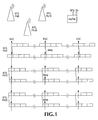
- Fig. 1 shows a PN sequence of each forward link pilot referenced to the ESC of the GPS signal.
- Fig. 2 shows an example where PN 10 is the strongest PN and is used to estimate a new timing reference timestamp.
- Fig. 3 is a flow diagram showing an embodiment of maintaining an instrument timing reference.
- Fig. 4 is a flow diagram showing an embodiment of maintaining an instrument timing reference.
- Fig. 5 illustrates a user interface for entering a reference PN offset to be used for estimating a new timing reference timestamp.
- the actual CDMA signal to be measured is also used to derive timing information and make the desired identification.
- This ability is referred to herein as PN Sync mode.
- the NetTek would not have absolute timing signals, as it may experience delay from the base station's antenna to the YBT250; therefore, the received CDMA signal will not be exactly aligned with the even second clock mark of the GPS time.
- it should be good enough to identify PN Offset since the base stations are not moving and the coverage range of a base station is intentionally relatively short with respect to the base stations' relative PN Offsets. Using a known PN Offset to derive the timing reference would allow the NetTek to identify all other PN Offsets.
- Figure 1 shows the PN sequence of each forward link pilot referenced to the timing reference, the Even Second Clock (ESC) of the GPS signal, with offsets 0, 10, and 20 respectively at the base station and at the input of the NetTek (delayed version).
- ESC Even Second Clock
- the derived timing reference will be aligned to the strongest PN offset, which corresponds to the highest-powered pilot.
- the tau results will be relative to the derived timing reference.
- Tau refers to the timing error, such as the timing error in PN chips, between the ideal and measured PN offset starting time. Therefore, tau values are not reported to the user as the values do not represent the error with respect to the CDMA timing reference.
- the test instrument After a GPS signal is obtained and an embodiment of a test instrument according to the present invention has measured an existing BTS, if the GPS signal is lost, the test instrument goes into a PN Sync mode. As long as the instrument continues to measure at least 1 PN offset in a reasonable amount of time, the instrument will derive its time reference from that Base Station and be able to identify other PN offsets. A reasonable amount of time corresponds to a length of time during which the drifting of the instrument's oscillator while no PN offset is measured does not cause an error in the next estimated PN offset value. In some embodiments, the instrument derive its time reference as long as the instrument continues to measure at least 1 PN offset. The estimated timing reference can be viewed as an extrapolation of the previously acquired GPS signal using the CDMA signal to correct for the drifting of the internal oscillator.
- Figure 2 illustrates an example where PN 10 is the strongest PN, which was identified using the last ESC timing reference.
- the length between two timing reference marks is a multiple of the frame length.
- An embodiment of the present instrument corrects for the drifting of its internal oscillator by relying on the two timing references being a multiple of the frame length. This allows the instrument to maintain internal timing with sufficient precision to measure PN offsets.
- the estimated timing reference timestamp is found using the following steps:
- PNX FB_Timestamp X_Timestamp - PNOSX * K PN - PNXTau * K Tsu ,
- the distance between the frame boundary and the current timing reference should be a multiple of the frame length. If not, it is assumed to be due to internal oscillator drifting.
- Distance FB_Timestamp - CurrentTmgRefTimestamp
- EstTmgRefTimestamp CurrentTmgRefTimestamp + Distance * 1 + TmgError
- EstTmgRefTimestamp EstTmgRefTimestamp + StrongestPNTau * K Tau
- the new estimated timing reference timestamp will be used for the next measurement, such as a scanner measurement.
- the measured tau will be expected to be 0, as the estimated timing reference is aligned to it.
- a deviation will be mainly due to internal oscillator drifting, which will be corrected in the next estimation.
- the strongest PN offset changes, the next estimated timing reference will be aligned to the new strongest PN offset.
- the next estimated timing reference will be determined using the process outlined above.
- Embodiments of this process rely on continuous measurement results to keep track of timing.
- PN offset values may change if the oscillator has drifted too much, for example if the oscillator has drifted significantly enough to misidentify the PN offset. If this occurs, the instrument may be moved to a location where the instrument is capable of reestablishing a GPS sync and then continue with the procedure described above.
- a Recovery PN offset process is used.
- a user will be able to enter the PN offset value of the dominant BTS, enabling the estimated timing reference stamp to be used even if a GPS lock was never established.
- Embodiments of the instrument derive its timing reference based upon the provided PN offset value and use it as a reference to measure other PN offset values.
- the first derived timing reference is estimated by taking into account the identity of the strongest PN offset, as provided by a user, for example.
- This embodiment is applicable to scanners capable of making relative measurement in the absence of a timing reference, such as a cdma2000 PN scanner in Tektronix' NETTEK analyzer.
- the measurement process utilizes the sample index for the strongest PN offset, and the acquisition timestamp, along with the identity of the strongest PN offset, which is provided by the user in some embodiments of the present invention.
- the sample index of the PN sequence can be computed.
- Fig. 3 is a flow diagram that illustrates the steps in an embodiment of a method according to the present invention.
- a clock is extracted from a GPS signal. This clock is for example the Even Second Clock (ESC) taken from the GPS signal.
- a PN offset is measured for a Base Transceiver Station (BTS) as provided at step 32.
- BTS Base Transceiver Station
- a time reference is derived from the BTS signal, for example using the PN offset as provided at step 34.
- the derived time reference can be adjusted to account for the tau value associated with the BTS PN offset measurement. That time reference is then used to identify the PN offset of a subsequent BTS, as provided at step 36.
- an optional additional process may be performed in the event that the signal from the first BTS is lost.
- a time reference is derived from a different BTS when the first BT signal is lost and further PN offsets are identified using this derived time reference at step 40.
- each of the derived timing references relates back in a known manner to the original GPS time reference it is still possible to maintain some continuity between the various PN offset measurement that are being made, despite losing the GPS signal or losing one or more BTS signals.
- Fig. 4 is a flow diagram that illustrates the steps in an embodiment of a method according to the present invention.
- a user provides a reference PN offset for a first BTS.
- a time reference is derived from the reference PN offset as provided at step 44. That time reference is then used to identify the PN offset of a subsequent BTS, as provided at step 46.
- an optional additional process may be performed in the event that the signal from the first BTS is lost.
- a time reference is derived from a different BTS when the first BT signal is lost and further PN offsets are identified using this derived time reference at step 50.
- Fig, 5 shows an embodiment of a user interface enabling a user to provide the PN offset to be used as the timing reference information. For example, a user may enter the Reference PN offset that corresponds to the dominant PN in the area.
- CDMA signal as a timing reference will allow embodiments of the present invention to identify BTS PN offset values indoors without a GPS timing signal.
Landscapes
- Engineering & Computer Science (AREA)
- Radar, Positioning & Navigation (AREA)
- Remote Sensing (AREA)
- Computer Networks & Wireless Communication (AREA)
- Physics & Mathematics (AREA)
- General Physics & Mathematics (AREA)
- Signal Processing (AREA)
- Position Fixing By Use Of Radio Waves (AREA)
- Mobile Radio Communication Systems (AREA)
- Synchronisation In Digital Transmission Systems (AREA)
Abstract
Description
- Embodiments of the present invention relate to test instruments, and more particularly to portable test instruments for measuring communications signals.
- Portable test instruments, such as those used in communications testing to test wireless network base stations, and transmitters, for voice, data or other communications, rely on a timing reference for certain types of measurements, or to correlate measurements in time. An available timing source that has been used for outdoor testing is a global positioning system (GPS) signal which is provided by a GPS satellite. A GPS signal is not typically available in an indoor environment. However, there is still a desire to provide testing of wireless communications systems within indoor environments.
- Accordingly, it would be useful to be able to identify and use an alternative timing reference. It would also be useful to be able to correlate the alternative timing reference with the GPS timing reference. An embodiment of the present method of maintaining a timing reference for a mobile communications signal is provided. A clock signal is extracted from a GPS signal. The PN offset for a BTS is measured for use in deriving a time reference. When the GPS signal is lost, a time reference is derived. In an embodiment, the strongest BTS signal available is used to provide the PN offset value and for deriving the time reference. This time reference is then used to measure other PN offsets.
- In further embodiments, a subsequent BTS PN offset may be used to provide a time reference in the event that the previous BTS signal becomes lost as well. This process can be repeated as necessary to provide a time reference, and the time reference will have relate back to the original GPS time reference.
- In an alternative embodiment, where no GPS value is available to begin with, a PN offset value can be provided, for example manually to provide an starting point for deriving a time reference.
-
Fig. 1 shows a PN sequence of each forward link pilot referenced to the ESC of the GPS signal. -
Fig. 2 shows an example where PN 10 is the strongest PN and is used to estimate a new timing reference timestamp. -
Fig. 3 is a flow diagram showing an embodiment of maintaining an instrument timing reference. -
Fig. 4 is a flow diagram showing an embodiment of maintaining an instrument timing reference. -
Fig. 5 illustrates a user interface for entering a reference PN offset to be used for estimating a new timing reference timestamp. - As part of the ability to identify different PN Offset values while within indoor environments, for the CDMA family of standards, a means of obtaining a timing reference - without access to a GPS signal was needed.
- In an embodiment of the present test instrument, such as the NETTEK™ YBT250 by Tektronix, Inc., the actual CDMA signal to be measured is also used to derive timing information and make the desired identification. This ability is referred to herein as PN Sync mode. While under this "PN Sync" mode, the NetTek would not have absolute timing signals, as it may experience delay from the base station's antenna to the YBT250; therefore, the received CDMA signal will not be exactly aligned with the even second clock mark of the GPS time. However, it should be good enough to identify PN Offset since the base stations are not moving and the coverage range of a base station is intentionally relatively short with respect to the base stations' relative PN Offsets. Using a known PN Offset to derive the timing reference would allow the NetTek to identify all other PN Offsets.
-
Figure 1 shows the PN sequence of each forward link pilot referenced to the timing reference, the Even Second Clock (ESC) of the GPS signal, withoffsets - The derived timing reference will be aligned to the strongest PN offset, which corresponds to the highest-powered pilot. The tau results will be relative to the derived timing reference. Tau refers to the timing error, such as the timing error in PN chips, between the ideal and measured PN offset starting time. Therefore, tau values are not reported to the user as the values do not represent the error with respect to the CDMA timing reference.
- After a GPS signal is obtained and an embodiment of a test instrument according to the present invention has measured an existing BTS, if the GPS signal is lost, the test instrument goes into a PN Sync mode. As long as the instrument continues to measure at least 1 PN offset in a reasonable amount of time, the instrument will derive its time reference from that Base Station and be able to identify other PN offsets. A reasonable amount of time corresponds to a length of time during which the drifting of the instrument's oscillator while no PN offset is measured does not cause an error in the next estimated PN offset value. In some embodiments, the instrument derive its time reference as long as the instrument continues to measure at least 1 PN offset. The estimated timing reference can be viewed as an extrapolation of the previously acquired GPS signal using the CDMA signal to correct for the drifting of the internal oscillator.
-
Figure 2 illustrates an example where PN 10 is the strongest PN, which was identified using the last ESC timing reference. The length between two timing reference marks is a multiple of the frame length. An embodiment of the present instrument corrects for the drifting of its internal oscillator by relying on the two timing references being a multiple of the frame length. This allows the instrument to maintain internal timing with sufficient precision to measure PN offsets. - In an embodiment of the present instrument, the estimated timing reference timestamp is found using the following steps:
- This can be done using the acquisition timestamp, and the equivalent PN offset and tau for that timestamp.
For any PNOS, say PNX
Where, - FB_Timestamp
- Frame boundary timestamp in clock ticks
- X_Timestamp
- Acquisition timestamp for X in clock ticks
- PNOSX
- PNOS for the PN sequence at the acquisition timestamp for X
- PNXTau
- Tau, in chips, of the PN sequence at the acquisition timestamp for X
- KPN
- Number of clock ticks per 64 chips
- KTau
- Number of clock ticks per chip
- The distance between the frame boundary and the current timing reference should be a multiple of the frame length. If not, it is assumed to be due to internal oscillator drifting.


-

-

- Embodiments of this process rely on continuous measurement results to keep track of timing. PN offset values may change if the oscillator has drifted too much, for example if the oscillator has drifted significantly enough to misidentify the PN offset. If this occurs, the instrument may be moved to a location where the instrument is capable of reestablishing a GPS sync and then continue with the procedure described above.
- In alternative embodiments, a Recovery PN offset process is used. In these alternative embodiments, a user will be able to enter the PN offset value of the dominant BTS, enabling the estimated timing reference stamp to be used even if a GPS lock was never established. Embodiments of the instrument derive its timing reference based upon the provided PN offset value and use it as a reference to measure other PN offset values. The first derived timing reference is estimated by taking into account the identity of the strongest PN offset, as provided by a user, for example. This embodiment is applicable to scanners capable of making relative measurement in the absence of a timing reference, such as a cdma2000 PN scanner in Tektronix' NETTEK analyzer.
- The measurement process utilizes the sample index for the strongest PN offset, and the acquisition timestamp, along with the identity of the strongest PN offset, which is provided by the user in some embodiments of the present invention. Using the strongest PN sample index, and its identity, the sample index of the PN sequence can be computed. The frame boundary may be estimated using the acquisition time stamp:

-
Fig. 3 is a flow diagram that illustrates the steps in an embodiment of a method according to the present invention. As shown, atstep 30, a clock is extracted from a GPS signal. This clock is for example the Even Second Clock (ESC) taken from the GPS signal. A PN offset is measured for a Base Transceiver Station (BTS) as provided atstep 32. When the GPS signal is lost a time reference is derived from the BTS signal, for example using the PN offset as provided atstep 34. In some embodiments the derived time reference can be adjusted to account for the tau value associated with the BTS PN offset measurement. That time reference is then used to identify the PN offset of a subsequent BTS, as provided atstep 36. In a further embodiment, an optional additional process may be performed in the event that the signal from the first BTS is lost. As shown atstep 38, a time reference is derived from a different BTS when the first BT signal is lost and further PN offsets are identified using this derived time reference atstep 40. - As each of the derived timing references relates back in a known manner to the original GPS time reference it is still possible to maintain some continuity between the various PN offset measurement that are being made, despite losing the GPS signal or losing one or more BTS signals.
-
Fig. 4 is a flow diagram that illustrates the steps in an embodiment of a method according to the present invention. As shown, atstep 42, a user provides a reference PN offset for a first BTS. A time reference is derived from the reference PN offset as provided atstep 44. That time reference is then used to identify the PN offset of a subsequent BTS, as provided atstep 46. In a further embodiment, an optional additional process may be performed in the event that the signal from the first BTS is lost. As shown atstep 48, a time reference is derived from a different BTS when the first BT signal is lost and further PN offsets are identified using this derived time reference atstep 50. -
Fig, 5 shows an embodiment of a user interface enabling a user to provide the PN offset to be used as the timing reference information. For example, a user may enter the Reference PN offset that corresponds to the dominant PN in the area. - Using the CDMA signal as a timing reference will allow embodiments of the present invention to identify BTS PN offset values indoors without a GPS timing signal.
- Various embodiments of the present invention have been described above by way of illustration. However, the above description should not limit the scope of the invention, which should be determined by the following claims.

Using the parameters for the strongest PN offset, PN 10 in this example, the timestamp for PN sequence at PN 10 can be derived.

From (1) and (2),

Claims (12)
- A method of maintaining a timing reference for a mobile communications signal comprising;extracting an Even Second Clock (ESC) from a global positioning system (GPS) signal;measuring a PN offset for a first Base Transceiver Station (BTS);deriving a time reference from the first BTS when the GPS signal is lost; andidentifying a second PN offset for a second BTS based upon the derived time reference.
- The method of claim 1, wherein the first BTS has the strongest signal.
- The method of claim 1, wherein a frame boundary of a CDMA signal is used when deriving the time reference.
- The method of claim 1, wherein tau is adjusted form when deriving the time reference.
- The method of claim 1, further comprising deriving a time reference from a different BTS other than the first BTS when the first BTS signal is lost.
- The method of claim 5, wherein the different BTS has the strongest signal at the time when the first BTS signal is lost.
- A method of maintaining a timing reference in the absence of a global positioning system (GPS) Even Second Clock (ESC) timing reference comprising:obtaining a value for a PN offset for a first Base Transceiver Station (BTS);deriving a time reference from the first BTS; andidentifying a second PN offset for a second BTS based upon the derived time reference.
- The method of claim 7, wherein the first BTS has the strongest signal.
- The method of claim 7, wherein a frame boundary of a CDMA signal is used when deriving the time reference.
- The method of claim 7, wherein tau is adjusted form when deriving the time reference.
- The method of claim 7, further comprising deriving a time reference from a different BTS other than the first BTS when the first BTS signal is lost.
- The method of claim 11, wherein the different BTS has the strongest signal at the time when the first BTS signal is lost.
Applications Claiming Priority (2)
| Application Number | Priority Date | Filing Date | Title |
|---|---|---|---|
| US90838607P | 2007-03-27 | 2007-03-27 | |
| US12/050,103 US8184608B2 (en) | 2007-03-27 | 2008-03-17 | System and method for using CDMA PN offset to maintain instrument timing reference |
Publications (2)
| Publication Number | Publication Date |
|---|---|
| EP1976156A2 true EP1976156A2 (en) | 2008-10-01 |
| EP1976156A3 EP1976156A3 (en) | 2011-01-19 |
Family
ID=39561834
Family Applications (1)
| Application Number | Title | Priority Date | Filing Date |
|---|---|---|---|
| EP08153264A Withdrawn EP1976156A3 (en) | 2007-03-27 | 2008-03-26 | System and method for using CDMA PN offset to maintain instrument timing reference |
Country Status (3)
| Country | Link |
|---|---|
| US (1) | US8184608B2 (en) |
| EP (1) | EP1976156A3 (en) |
| JP (1) | JP5057336B2 (en) |
Families Citing this family (4)
| Publication number | Priority date | Publication date | Assignee | Title |
|---|---|---|---|---|
| US8274947B1 (en) * | 2007-10-05 | 2012-09-25 | Zte (Usa) Inc. | Providing timing reference for femto cell in wireless communication networks |
| US20120231807A1 (en) * | 2011-03-11 | 2012-09-13 | Qualcomm Incorporated | Frequency and timing control for femtocell |
| US10218408B1 (en) * | 2017-08-23 | 2019-02-26 | Higher Ground Llc | Synchronized CPDMA (code phase division multiple access) |
| CN118795868B (en) * | 2024-08-26 | 2025-03-25 | 珠海广通车辆制造有限公司 | A system for analyzing vehicle status failure |
Family Cites Families (29)
| Publication number | Priority date | Publication date | Assignee | Title |
|---|---|---|---|---|
| KR100241725B1 (en) * | 1997-08-02 | 2000-02-01 | 윤종용 | Synchronizing method in distributed networking system and apparatus thereof |
| US5872774A (en) * | 1997-09-19 | 1999-02-16 | Qualcomm Incorporated | Mobile station assisted timing synchronization in a CDMA communication system |
| US6208871B1 (en) * | 1998-02-27 | 2001-03-27 | Motorola, Inc. | Method and apparatus for providing a time adjustment to a wireless communication system |
| US6590881B1 (en) * | 1998-12-04 | 2003-07-08 | Qualcomm, Incorporated | Method and apparatus for providing wireless communication system synchronization |
| KR20000045213A (en) * | 1998-12-30 | 2000-07-15 | 김영환 | Method of operating base station for compensating path delay between cdma mobile communication base station and mobile phone |
| HK1043012B (en) * | 1999-02-26 | 2005-10-28 | 高通股份有限公司 | Method for handoff between an asynchronous cdma base station and a synchronous cdma base station |
| US7053824B2 (en) * | 2001-11-06 | 2006-05-30 | Global Locate, Inc. | Method and apparatus for receiving a global positioning system signal using a cellular acquisition signal |
| US6577616B1 (en) * | 1999-12-29 | 2003-06-10 | Nortel Networks Limited | Systems and methods for implementing large CDMA cell sizes |
| US6650653B1 (en) * | 2000-01-19 | 2003-11-18 | Mitsubishi Electric Research Laboratories, Inc. | Software-based digital receiver adaptable to multiple multiplexing schemes |
| US6775252B1 (en) * | 2000-03-31 | 2004-08-10 | Qualcomm, Inc. | Dynamic adjustment of search window size in response to signal strength |
| US6813257B1 (en) * | 2000-06-26 | 2004-11-02 | Motorola, Inc. | Apparatus and methods for controlling short code timing offsets in a CDMA system |
| JP3656526B2 (en) | 2000-07-17 | 2005-06-08 | 株式会社日立製作所 | Wireless communication base station, wireless position measuring system, transmission timing measuring device, and position measuring center device |
| US7039098B2 (en) * | 2000-08-07 | 2006-05-02 | Qualcomm Incorporated | Method and apparatus for base station and mobile station time calibration |
| KR20020034517A (en) | 2000-11-02 | 2002-05-09 | 조정남 | Apparatus for setting standard time and method thereof |
| JP4627870B2 (en) * | 2000-11-27 | 2011-02-09 | 京セラ株式会社 | Mobile communication system and base station apparatus |
| GB0101200D0 (en) | 2001-01-17 | 2001-02-28 | Roke Manor Research | Nodeb frequency acquisition |
| JP3839277B2 (en) * | 2001-05-25 | 2006-11-01 | 三菱電機株式会社 | Wireless communication system and base station frame synchronization method |
| JP2003087175A (en) * | 2001-09-10 | 2003-03-20 | Hitachi Kokusai Electric Inc | Mesh wireless station communication system |
| KR100479169B1 (en) * | 2001-10-26 | 2005-03-25 | 삼성전자주식회사 | Apparatus for cell search and method thereof in mobile communication system |
| US7162261B1 (en) * | 2002-02-27 | 2007-01-09 | Sprint Communications Company L.P. | Method and device for identifying antennae to transmit wireless signals |
| US6937872B2 (en) * | 2002-04-15 | 2005-08-30 | Qualcomm Incorporated | Methods and apparatuses for measuring frequencies of basestations in cellular networks using mobile GPS receivers |
| US7197288B1 (en) * | 2002-06-24 | 2007-03-27 | Sprint Spectrum L.P. | Method and system of spread spectrum modulation |
| US7373118B1 (en) * | 2003-06-27 | 2008-05-13 | Sprint Spectrum L.P. | Method and system for facilitating transmission of analog signals to a wireless terminal |
| CN1890900B (en) | 2003-12-08 | 2010-06-16 | 高通股份有限公司 | Method and apparatus for high precision synchronization of test devices |
| US7929487B2 (en) * | 2004-01-16 | 2011-04-19 | Alcatel-Lucent Usa Inc. | Method and apparatus for cellular communication over data networks |
| US7240252B1 (en) * | 2004-06-30 | 2007-07-03 | Sprint Spectrum L.P. | Pulse interference testing in a CDMA communication system |
| JP2006217359A (en) * | 2005-02-04 | 2006-08-17 | Matsushita Electric Ind Co Ltd | Synchronization apparatus and synchronization method for mobile communication system |
| US7680075B2 (en) * | 2006-05-17 | 2010-03-16 | Alcatel-Lucent Usa Inc. | Identification of base stations |
| US20090310570A1 (en) * | 2008-06-16 | 2009-12-17 | Rivada Networks Llc | Method and Systems Providing Peer-to-Peer Direct-Mode-Only Communications on CDMA Mobile Devices |
-
2008
- 2008-03-17 US US12/050,103 patent/US8184608B2/en not_active Expired - Fee Related
- 2008-03-26 EP EP08153264A patent/EP1976156A3/en not_active Withdrawn
- 2008-03-27 JP JP2008084654A patent/JP5057336B2/en not_active Expired - Fee Related
Non-Patent Citations (1)
| Title |
|---|
| ANDREW MICELI: "Wireless Technicin's Handbook", 1 January 2003, ARTECH HOUSE, Norwood, pages: 253-254 * |
Also Published As
| Publication number | Publication date |
|---|---|
| EP1976156A3 (en) | 2011-01-19 |
| JP2008245289A (en) | 2008-10-09 |
| US20090073951A1 (en) | 2009-03-19 |
| JP5057336B2 (en) | 2012-10-24 |
| US8184608B2 (en) | 2012-05-22 |
Similar Documents
| Publication | Publication Date | Title |
|---|---|---|
| JP5108138B2 (en) | Method and apparatus for time calibration of base station and mobile station | |
| JP4680893B2 (en) | Virtual real-time clock based on time information from multiple communication systems | |
| US6246673B1 (en) | Method and system for handoff between an asynchronous CDMA base station and a synchronous CDMA base station | |
| EP1016225B1 (en) | Mobile station assisted timing synchronization in a cdma communication system | |
| EP1504540B1 (en) | System and method for the detection and compensation of radio signal time of arrival errors | |
| JP4482645B2 (en) | Method and apparatus for performing wireless communication system synchronization | |
| US6201802B1 (en) | Method and apparatus for analyzing base station timing | |
| KR101215766B1 (en) | Method of and system for calibrating a repeater | |
| SK10662000A3 (en) | TIME SYNCHRONIZATION USING MOBILE STATIONS IN CDMA COMMUNICATION SYSTEM | |
| WO2000051393A9 (en) | Method and system for handoff between an asynchronous cdma base station and a synchronous cdma base station | |
| US8184608B2 (en) | System and method for using CDMA PN offset to maintain instrument timing reference | |
| US7330458B2 (en) | Method for synchronizing terrestrial nodes equipped with GNSS receivers and belonging to a terrestrial network | |
| US20020110151A1 (en) | Method and apparatus for CDMA pn scanning at indoor and other obstructed locations | |
| JP4424576B2 (en) | Improved use of a global location system for radio transmitter location | |
| CN108347765B (en) | Pseudo-range measurement method based on CDMA forward link signal | |
| JP2003185727A (en) | Server, mobile terminal device, and position detection system | |
| CN113489509A (en) | Time-frequency synchronization method and device among large-scale GNSS pseudolites | |
| Shutin et al. | LDACS1 for APNT—Planning and realization of a flight measurement campaign | |
| EP1596508B1 (en) | Method and apparatus for base station and mobile station time calibration | |
| KR20030046682A (en) | Radio network controller/node b for detecting position of user equipment using differential global positioning system in mobile communication system | |
| HK1055517B (en) | Method and apparatus for base station and mobile station time calibration | |
| HK1073937B (en) | Method and apparatus for base station and mobile station time calibration | |
| HK1073936B (en) | Method and apparatus for base station and mobile station time calibration |
Legal Events
| Date | Code | Title | Description |
|---|---|---|---|
| PUAI | Public reference made under article 153(3) epc to a published international application that has entered the european phase |
Free format text: ORIGINAL CODE: 0009012 |
|
| AK | Designated contracting states |
Kind code of ref document: A2 Designated state(s): AT BE BG CH CY CZ DE DK EE ES FI FR GB GR HR HU IE IS IT LI LT LU LV MC MT NL NO PL PT RO SE SI SK TR |
|
| AX | Request for extension of the european patent |
Extension state: AL BA MK RS |
|
| PUAL | Search report despatched |
Free format text: ORIGINAL CODE: 0009013 |
|
| AK | Designated contracting states |
Kind code of ref document: A3 Designated state(s): AT BE BG CH CY CZ DE DK EE ES FI FR GB GR HR HU IE IS IT LI LT LU LV MC MT NL NO PL PT RO SE SI SK TR |
|
| AX | Request for extension of the european patent |
Extension state: AL BA MK RS |
|
| 17P | Request for examination filed |
Effective date: 20110505 |
|
| 17Q | First examination report despatched |
Effective date: 20110711 |
|
| AKX | Designation fees paid |
Designated state(s): AT BE BG CH CY CZ DE DK EE ES FI FR GB GR HR HU IE IS IT LI LT LU LV MC MT NL NO PL PT RO SE SI SK TR |
|
| STAA | Information on the status of an ep patent application or granted ep patent |
Free format text: STATUS: THE APPLICATION IS DEEMED TO BE WITHDRAWN |
|
| 18D | Application deemed to be withdrawn |
Effective date: 20131001 |