EP1976100A1 - Phase insulator - Google Patents
Phase insulator Download PDFInfo
- Publication number
- EP1976100A1 EP1976100A1 EP08153522A EP08153522A EP1976100A1 EP 1976100 A1 EP1976100 A1 EP 1976100A1 EP 08153522 A EP08153522 A EP 08153522A EP 08153522 A EP08153522 A EP 08153522A EP 1976100 A1 EP1976100 A1 EP 1976100A1
- Authority
- EP
- European Patent Office
- Prior art keywords
- portions
- phase
- insulating sheet
- coil
- stator core
- Prior art date
- Legal status (The legal status is an assumption and is not a legal conclusion. Google has not performed a legal analysis and makes no representation as to the accuracy of the status listed.)
- Withdrawn
Links
- 239000012212 insulator Substances 0.000 title claims abstract description 79
- 239000000463 material Substances 0.000 claims abstract description 31
- 229920003207 poly(ethylene-2,6-naphthalate) Polymers 0.000 claims description 10
- 239000011112 polyethylene naphthalate Substances 0.000 claims description 10
- 238000003466 welding Methods 0.000 claims description 4
- -1 polyethylene naphthalate Polymers 0.000 claims description 3
- 229920001577 copolymer Polymers 0.000 claims description 2
- 238000007493 shaping process Methods 0.000 description 8
- 238000009434 installation Methods 0.000 description 6
- 238000000034 method Methods 0.000 description 5
- 239000000126 substance Substances 0.000 description 4
- 238000009413 insulation Methods 0.000 description 3
- 238000002360 preparation method Methods 0.000 description 3
- 230000000694 effects Effects 0.000 description 2
- 238000004519 manufacturing process Methods 0.000 description 2
- 229920000139 polyethylene terephthalate Polymers 0.000 description 2
- 239000005020 polyethylene terephthalate Substances 0.000 description 2
- 239000003507 refrigerant Substances 0.000 description 2
- 239000000853 adhesive Substances 0.000 description 1
- 230000001070 adhesive effect Effects 0.000 description 1
- 239000000314 lubricant Substances 0.000 description 1
- 238000005461 lubrication Methods 0.000 description 1
- 238000003754 machining Methods 0.000 description 1
- 239000003595 mist Substances 0.000 description 1
- 229920000728 polyester Polymers 0.000 description 1
- 238000003825 pressing Methods 0.000 description 1
- 239000011347 resin Substances 0.000 description 1
- 229920005989 resin Polymers 0.000 description 1
- 230000000717 retained effect Effects 0.000 description 1
- 238000000926 separation method Methods 0.000 description 1
- 239000010409 thin film Substances 0.000 description 1
- 239000002699 waste material Substances 0.000 description 1
- 238000004804 winding Methods 0.000 description 1
Images


Classifications
-
- H—ELECTRICITY
- H02—GENERATION; CONVERSION OR DISTRIBUTION OF ELECTRIC POWER
- H02K—DYNAMO-ELECTRIC MACHINES
- H02K3/00—Details of windings
- H02K3/32—Windings characterised by the shape, form or construction of the insulation
- H02K3/38—Windings characterised by the shape, form or construction of the insulation around winding heads, equalising connectors, or connections thereto
Definitions
- the present invention relates to a phase insulator, more particularly, a phase insulator having insulating sheet portions and bridge portions for connecting the insulating sheet portions.
- the insulating sheet portions are disposed at both ends of a stator core for insulating between coil ends of stator coils.
- the bridge portions are inserted in slots between teeth of the stator core.
- stator coils are inserted in slots of a stator core of a stator in an electric motor.
- Each coil is arranged so as to have a different phase with each other.
- the coil ends of each coil disposed at the stator core protrude at both axial end surfaces of the stator core.
- the coil ends are arranged so as to overlap in the radial direction with each other.
- a phase insulator with a sheet shape is disposed between the coils with different phases to insulate between the coils.
- an appropriate phase insulator for automation is formed with a pair of insulating portions and bridge portions.
- the insulating portions insulate coil ends at the both end surfaces of the stator.
- the bridge portions connect the pair of the insulating portions.
- phase insulator is disclosed in Unexamined Japanese Patent Publication No. 03-40731 , whose corresponding U. S. Patent is published as U.S. Patent No. 4,266,994 .
- the phase insulator includes a pair of planar portions and connectors.
- the planar portions correspond to the above-described insulating portions.
- the connectors correspond to the above-described bridge portions.
- the planar portions are made of polyethylene terephthalate (PET).
- PET polyethylene terephthalate
- the connectors are made of polyester monofilament, which is stretched in advance to be straightened.
- the insulating portions and the bridge portions are connected by ultrasonic welding. In this type of phase insulator, the bridge portions of the phase insulator are easily inserted in slots of a stator core.
- the insulating portions and the bridge portions may be torn, or the welded regions may be disjointed.
- a shaping process is performed for shaping the coil ends of the coils disposed at the stator core. Forces appropriate for shaping coil ends are applied to the coil ends and the phase insulators in the axial and radial directions of the stator core. The forces may be applied to the coil ends and the phase insulators in the direction to separate the insulating portions with each other. In this case, the insulating portions and the bridge portions may be separated from each other, or the insulating portions and the bridge portions may be torn.
- the insulating portions and the bridge portions are separated or torn, the insulating portions are misaligned from the predetermined position, and moved in the direction away from the end surfaces of the stator core. In this case, a part of each stator coil may contact with each other. Thus, the phase insulation between each coil end is not ensured when the phase insulator is moved apart from the stator coils. Additionally, the insulating portions or the bridge portions are separated or torn into pieces, and such pieces may exist as debris in the electric motor.
- the present invention is directed to a phase insulator in which an insulating sheet portion and a bridge portion are not to be separated, and the insulating sheet portion and the bridge portion are not to be torn after the phase insulator is installed to a stator core.
- a phase insulator for a stator of a motor insulates plural stator coils from each other.
- the stator has the stator coils inserted in slots in a stator core.
- the phase insulator includes insulating sheet portions and bridge portions.
- the insulating sheet portions are disposed at both end portions of the stator core for insulating between the coil ends of the stator coils.
- the insulating sheet portions are made of a first material.
- the bridge portions connect the insulating sheet portions.
- the bridge portions are inserted in the slots of the stator core.
- the bridge portions are made of a second material. The second material has higher elastic characteristics than the first material.
- a stator core of a stator is incorporated in an electric motor with three-phase distributed windings for an electric compressor.
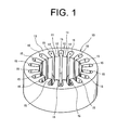
- a stator core 10 is formed with a substantially cylindrical shape.
- the stator core 10 has end surfaces 13, 14 at both axial end portions respectively.
- the end surfaces 13, 14 are formed perpendicular to the axial direction of the stator core 10.
- FIG. 1 is a perspective view, and the end surface 13 is shown in FIG. 1 .
- Teeth 11 are formed in the inner circumference of the stator core 10, and arranged in the circumferential direction of the stator core 10. The teeth 11 protrude toward the axial center of the stator core 10.
- Each of the teeth 11 has protruding portions 12 at the opposite side of the distal end thereof.
- the protruding portions 12 protrude in the circumferential direction.
- Slots 15 are formed between adjacent two teeth 11 respectively.
- Each slot 15 has a space which is formed so as to penetrate the stator core 10 in the axial direction.
- the slots 15 are aligned at regular intervals.
- Stator coils are inserted in the slots 15 such that any two adjacent slots 15 have respective stator coils with different phases from each other.
- the stator core 10 includes eighteen teeth 11 and eighteen slots 15. Accordingly, any two adjacent slots 15 are spaced from each other in the circumferential direction of the stator core 10 at an angular interval of 20°.
- the three-phase stator coils include a U-phase coil 16, a V-phase coil 17, and a W-phase coil 18.
- the stator coils 16, 17, 18 are formed such that enameled conductive wires are wound respectively.
- Each stator coil 16, 17, 18 is inserted in six of the eighteen slots 15.
- the stator coils 16, 17, 18 are arranged in the corresponding slots 15 which are spaced at an angular interval of 60° in the circumferential direction of the stator core 10.
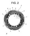
- the stator core 10 is in a state as shown in FIG.2 , and as shown schematically in FIG. 3 .
- the U-phase coil 16 passes through one of the slots 15 and the coil end of the coil 16 is exposed at the end surface 13. Then, the U-phase coil 16 passes through the third slot 15 from the foregoing slot 15 where the coil end of the coil 16 is exposed. The coil end of the U-phase coil 16 is exposed at the opposite end surface 14 of the stator core 10. Then, the U-phase coil 16 passes through the third slot 15 from the foregoing slot 15 where the coil end of the coil 16 is exposed at the end surface 14.
- the U-phase coil 16 is completely arranged in totally six slots 15 for the U-phase coil 16, the three coil ends are formed at the both end surfaces 13, 14 (shown in FIG. 6 ), respectively.
- the V-phase coil 17 is arranged in the slots 15 of the stator core 10 after the U-phase coil 16 is arranged.
- the V-phase coil 17 passes through one of the slots 15, which is next to the slot 15 for the U-phase coil 16.
- the three coil ends of the V-phase coil 17 are formed at the both end surfaces 13, 14, respectively.
- the W-phase coil 18 is arranged in the remained slots 15 after the V-phase coil 17 is arranged.
- the W-phase coil 18 is arranged in the similar way to the U-phase coil 16 and the V-phase coil 17.
- FIG. 2 shows only the coil ends of the stator coils 16, 17, 18 at the end surface 13 of the stator core 10.
- the coil ends of the stator coils 16, 17, 18 at the end surface 14 are arranged similarly to those at the end surface 13 and therefore omitted.
- stator coils 16, 17, 18 are installed to the stator core 10 so as to have different phases with each other. Phase insulation is required between the coil ends of the different stator coils 16, 17, 18.
- a first phase insulator 20 and a second phase insulator 24 are incorporated between the coils 16, 17, 18.
- the first phase insulator 20 insulates between the U-phase coil 16 and the V-phase coil 17 at the coil ends, as shown in FIG. 2 and 3 .
- the first phase insulator 20 is installed to the stator core 10 after the installation of the U-phase coil 16 and before the installation of the V-phase coil 17 to the stator core 10.
- the second phase insulator 24 insulates between the V-phase coil 17 and the W-phase coil 18 at the coil ends.
- the second phase insulator 24 is installed to the stator core 10 after the installation of the V-phase coil 17 to the stator core 10.
- FIG. 4 shows the configuration of the first phase insulator 20.
- the first phase insulator 20 is formed with a thin film.
- the first phase insulator 20 includes a pair of insulating sheet portions 21 and bridge portions 22.
- the pair of insulating sheet portions 21 is disposed at the both end surfaces 13, 14 of the stator core 10 for insulating between the coil ends.
- the bridge portions 22 connect the pair of the insulating sheet portions 21.
- the insulating sheet portions 21 insulate the U-phase coil 16 and the V-phase coil 17 at the coil ends.
- the insulating sheet portions 21 are made of polyethylene naphthalate (hereinafter referred to as PEN) as a first material.
- PEN has excellent insulating properties and chemical resistance.
- the insulating sheet portions 21 have a sufficient length and width such that a single insulating sheet portion 21 insulates between the U-phase coil 16 and the V-phase coil 17 at the coil ends.
- the insulating sheet portions 21 have a sufficient length (in the vertical direction in the drawing of FIG. 4 ) to cover the entire area where the U-phase coil 16 and the V-phase coil 17 overlap with each other at the end surfaces 13, 14.
- the insulating sheet portions 21 have a sufficient width (in the lateral direction in the drawing of FIG. 4 ) to round completely along the stator core 10 at the inner periphery of the U-phase coil 16.
- the bridge portions 22 connect the pair of the insulating sheet portions 21.
- the bridge portions 22 are inserted in the slots 15 between the teeth 11 of the stator core 10.
- the bridge portions 22 are formed as an independent part from the insulating sheet portions 21.
- the bridge portions 22 of the preferred embodiment are cut out from a sheet made of tetrafluoroethylene -hexafluoropropylene copolymer (hereinafter referred to as FEP).
- FEP corresponds to a second material of the present invention. Both ends of the bridge portions 22 are overlapped on edge portions of the insulating sheet portions 21, and connected to the insulating sheet portions 21 by ultrasonic welding so as to form joints 23.
- FEP for the bridge portions 22 has an extremely low stress which is generated in response to the elongation rate, compared to PEN for the insulating sheet portions 21. That is, FEP as the material for the bridge portions 22 has higher elastic characteristics than PEN. Namely, in an electric compressor, a stator core of an electric motor is exposed in refrigerant gas and mist of lubrication oil. Therefore, FEP with excellent chemical resistance is an appropriate material for the bridge portions 22.
- the material and the configuration of the second phase insulator 24 is substantially the same as the first phase insulator 20, and the explanation in detail is omitted.
- a slot insulator (not shown) is arranged in each slot 15 in advance, independently from the phase insulators 20, 24.
- the slot insulators insulate between the stator core 10 and each coil 16, 17, 18.
- the U-phase coil 16 is arranged in the slots 15 of the stator core 10 so as to be wound around the teeth 11 of the stator core 10.
- FIG. 6 when the U-phase coil 16 is arranged in the slots 15 of the stator core 10, three coil ends are formed at the both end surfaces 13, 14 of the stator core 10, respectively.
- the first phase insulator 20 is installed to the stator core 10.
- Each bridge portion 22 of the first phase insulator 20 is inserted in the corresponding slots 15, and the first phase insulator 20 is retained at the stator core 10.
- the insulating sheet portions 21 are arranged circularly along the inner circumference of the coil ends of the U-phase coil 16.
- the above process is a preparation to arrange the V-phase coil 17 easily.
- the axial end portions of the coil ends are expanded radially outward.
- force is applied on the first phase insulator 20 in the direction to move the both insulating sheet portions 21 away from each other.
- the both insulating sheet portions 21 are drawn by the force and are moved away from each other.
- the force is applied to the bridge portions 22 in the direction to draw the bridge portions 22 in the longitudinal direction. Since the bridge portions 22 have higher elastic characteristics than the insulating portions 21, the bridge portions 22 are extended to absorb the force. Due to the extension of the bridge portions 22, an excessive tension does not act on the joints 23 between the insulating sheet portions 21 and the bridge portions 22. Therefore, the insulating sheet portions 21 and the bridge portions 22 are not separated nor torn. Thus, the insulating sheet portions 21 are not moved away from the coil ends.
- the V-phase coil 17 is installed to the stator core 10.
- the V-phase coil 17 is disposed along the inner circumference of the first phase insulator 20.
- the U-phase coil 16 and the V-phase coil 17 are insulated by the insulating sheet portions 21 of the first phase insulator 20.
- the second phase insulator 24 is installed to the stator core 10. After the second phase insulator 24 is arranged, the coil ends are deformed by the pressing force such that the end portions of the coil ends of the V-phase coil 17 face radially outward.
- the above process is a preparation to arrange the W-phase coil 18 easily.
- the W-phase coil 18 is installed to the stator core 10.
- the W-phase coil 18 is disposed along the inner circumferential surface of the second phase insulator 24.
- the V-phase coil 17 and the W-phase coil 18 are insulated by the insulating sheet portions of the second phase insulator 24.
- FIG. 2 shows this state.
- the coils 16, 17, 18 are insulated at the coil ends by the first and the second phase insulators 20, 24.
- the shaping process is performed.
- the whole coil ends at the end surfaces 13, 14 of the stator core 10 are pressed and shaped to form a ring shape in which the radial and the axial dimensions are substantially constant.
- force is applied on the first phase insulator 20 in the direction to move the insulating sheet portions 21 away from each other.
- the tension due to the force is absorbed by the extension of the bridge portions 22.
- the insulating sheet portions 21 and the bridge portions 22 are not separated nor torn.
- the separation and the breakage of the insulating sheet portions and the bridge portions are not caused in the second phase insulator 24, despite the force acting on the second phase insulator 24.
- the insulating sheet portions and the bridge portions are connected by an ultrasonic welding.
- the insulating sheet portions and the bridge portions may be adhered by an adhesive, or may be pressed so as to be connected with each other.
- the connecting portions between the insulating sheet portions and the bridge portions need to have sufficient strength. That is, the connecting portions need to withstand the stress generated by the tension of the bridge portions during the shaping process of the coil ends or the like.
- FEP is utilized as a material for the bridge portions.
- FEP has higher elastic characteristics compared to PEN for the insulating sheet portions.
- the materials for the insulating sheet portions and the bridge portions are not limited, as long as the difference in the elastic characteristics between the alternative materials is substantially the same level as that between PEN and FEN. Namely, when the phase insulator is used for an electric compressor, the phase insulator needs chemical resistance.
- the insulating sheet portions and the bridge portions may be preferably made of combination of resin series.
- the insulating sheet portions and the bridge portions of the phase insulator have the simplest shape so as not to waste sheet material.
- the configuration of the insulating sheet portions and the bridge portions is determined appropriately depending on the conditions of the stator core and the coil ends.
- a phase insulator for a stator of a motor insulates between stator coils.
- the stator has plural stator coils inserted in slots in a stator core.
- the phase insulator insulates stator coils from each other.
- the phase insulator includes insulating sheet portions and bridge portions.
- the insulating sheet portions are disposed at both end portions of the stator core for insulating between the coil ends of the stator coils.
- the insulating sheet portions are made of a first material.
- the bridge portions connect the insulating sheet portions.
- the bridge portions are inserted in the slots of the stator core.
- the bridge portions are made of a second material. The second material has higher elastic characteristics than the first material.
Landscapes
- Engineering & Computer Science (AREA)
- Power Engineering (AREA)
- Insulation, Fastening Of Motor, Generator Windings (AREA)
Abstract
Description
- The present invention relates to a phase insulator, more particularly, a phase insulator having insulating sheet portions and bridge portions for connecting the insulating sheet portions. The insulating sheet portions are disposed at both ends of a stator core for insulating between coil ends of stator coils. The bridge portions are inserted in slots between teeth of the stator core.
- Generally, plural stator coils are inserted in slots of a stator core of a stator in an electric motor. Each coil is arranged so as to have a different phase with each other. The coil ends of each coil disposed at the stator core protrude at both axial end surfaces of the stator core. The coil ends are arranged so as to overlap in the radial direction with each other. A phase insulator with a sheet shape is disposed between the coils with different phases to insulate between the coils. In recent years, automatic installation of a phase insulator to a stator core has been attempted in manufacturing an electric motor. It is well known that an appropriate phase insulator for automation is formed with a pair of insulating portions and bridge portions. The insulating portions insulate coil ends at the both end surfaces of the stator. The bridge portions connect the pair of the insulating portions.
- Such a phase insulator is disclosed in Unexamined Japanese Patent Publication No.
03-40731 U.S. Patent No. 4,266,994 . The phase insulator includes a pair of planar portions and connectors. The planar portions correspond to the above-described insulating portions. The connectors correspond to the above-described bridge portions. The planar portions are made of polyethylene terephthalate (PET). The connectors are made of polyester monofilament, which is stretched in advance to be straightened. The insulating portions and the bridge portions are connected by ultrasonic welding. In this type of phase insulator, the bridge portions of the phase insulator are easily inserted in slots of a stator core. - However, in manufacturing an electric motor incorporated with such a phase insulator, problems occur. During the processes after the installation of the phase insulator to the stator core, the insulating portions and the bridge portions may be torn, or the welded regions may be disjointed. For example, a shaping process is performed for shaping the coil ends of the coils disposed at the stator core. Forces appropriate for shaping coil ends are applied to the coil ends and the phase insulators in the axial and radial directions of the stator core. The forces may be applied to the coil ends and the phase insulators in the direction to separate the insulating portions with each other. In this case, the insulating portions and the bridge portions may be separated from each other, or the insulating portions and the bridge portions may be torn.
- When the insulating portions and the bridge portions are separated or torn, the insulating portions are misaligned from the predetermined position, and moved in the direction away from the end surfaces of the stator core. In this case, a part of each stator coil may contact with each other. Thus, the phase insulation between each coil end is not ensured when the phase insulator is moved apart from the stator coils. Additionally, the insulating portions or the bridge portions are separated or torn into pieces, and such pieces may exist as debris in the electric motor.
- The present invention is directed to a phase insulator in which an insulating sheet portion and a bridge portion are not to be separated, and the insulating sheet portion and the bridge portion are not to be torn after the phase insulator is installed to a stator core.
- In accordance with an aspect of the present invention, a phase insulator for a stator of a motor insulates plural stator coils from each other. The stator has the stator coils inserted in slots in a stator core. The phase insulator includes insulating sheet portions and bridge portions. The insulating sheet portions are disposed at both end portions of the stator core for insulating between the coil ends of the stator coils. The insulating sheet portions are made of a first material. The bridge portions connect the insulating sheet portions. The bridge portions are inserted in the slots of the stator core. The bridge portions are made of a second material. The second material has higher elastic characteristics than the first material.
- Other aspects and advantages of the invention will become apparent from the following description, taken in conjunction with the accompanying drawings, illustrating by way of example the principles of the invention.
- The features of the present invention that are believed to be novel are set forth with particularity in the appended claims. The invention together with objects and advantages thereof, may best be understood by reference to the following description of the presently preferred embodiments together with the accompanying drawings in which:
-
FIG. 1 is a perspective view of a stator core according to a preferred embodiment of the present invention; -
FIG. 2 is a plan view of the stator core where phase insulators are installed according to the preferred embodiment; -
FIG. 3 is a schematic plan view of the stator core ofFIG. 2 ; -
FIG. 4 is a plan view of the phase insulator according to the preferred embodiment; -
FIG. 5 is a graph showing a relation between elongation rate and stress of an insulating sheet portion (PEN) and a bridge portion (FEP); and -
FIG. 6 is a side view of a stator core where a U-phase coil and a first phase insulator are installed. - The following will describe a preferred embodiment according to the present invention with reference to
FIG. 1 through 6 . In the preferred embodiment, a stator core of a stator is incorporated in an electric motor with three-phase distributed windings for an electric compressor. As shown inFIG. 1 , astator core 10 is formed with a substantially cylindrical shape. Thestator core 10 hasend surfaces end surfaces stator core 10.FIG. 1 is a perspective view, and theend surface 13 is shown inFIG. 1 .Teeth 11 are formed in the inner circumference of thestator core 10, and arranged in the circumferential direction of thestator core 10. Theteeth 11 protrude toward the axial center of thestator core 10. - Each of the
teeth 11 has protrudingportions 12 at the opposite side of the distal end thereof. Theprotruding portions 12 protrude in the circumferential direction.Slots 15 are formed between adjacent twoteeth 11 respectively. Eachslot 15 has a space which is formed so as to penetrate thestator core 10 in the axial direction. Theslots 15 are aligned at regular intervals. Stator coils are inserted in theslots 15 such that any twoadjacent slots 15 have respective stator coils with different phases from each other. According to the preferred embodiment, thestator core 10 includes eighteenteeth 11 and eighteenslots 15. Accordingly, any twoadjacent slots 15 are spaced from each other in the circumferential direction of thestator core 10 at an angular interval of 20°. - The three-phase stator coils include a
U-phase coil 16, a V-phase coil 17, and a W-phase coil 18. The stator coils 16, 17, 18 are formed such that enameled conductive wires are wound respectively. Eachstator coil slots 15. For example, between the twoslots 15 in which theU-phase coil 16 is inserted, there exist twoslots 15 in which the V-phase coil 17 and the W-phase coil 18 are inserted respectively. That is, the stator coils 16, 17, 18 are arranged in the correspondingslots 15 which are spaced at an angular interval of 60° in the circumferential direction of thestator core 10. When all thecoils slots 15 of thestator core 10, thestator core 10 is in a state as shown inFIG.2 , and as shown schematically inFIG. 3 . - Following will describe the coil ends of the stator coils 16, 17, 18 which are installed to the
stator core 10. TheU-phase coil 16 passes through one of theslots 15 and the coil end of thecoil 16 is exposed at theend surface 13. Then, theU-phase coil 16 passes through thethird slot 15 from the foregoingslot 15 where the coil end of thecoil 16 is exposed. The coil end of theU-phase coil 16 is exposed at theopposite end surface 14 of thestator core 10. Then, theU-phase coil 16 passes through thethird slot 15 from the foregoingslot 15 where the coil end of thecoil 16 is exposed at theend surface 14. When theU-phase coil 16 is completely arranged in totally sixslots 15 for theU-phase coil 16, the three coil ends are formed at the both end surfaces 13, 14 (shown inFIG. 6 ), respectively. - The V-
phase coil 17 is arranged in theslots 15 of thestator core 10 after theU-phase coil 16 is arranged. The V-phase coil 17 passes through one of theslots 15, which is next to theslot 15 for theU-phase coil 16. Similarly to theU-phase coil 16, the three coil ends of the V-phase coil 17 are formed at the both end surfaces 13, 14, respectively. The W-phase coil 18 is arranged in the remainedslots 15 after the V-phase coil 17 is arranged. The W-phase coil 18 is arranged in the similar way to theU-phase coil 16 and the V-phase coil 17.FIG. 2 shows only the coil ends of the stator coils 16, 17, 18 at theend surface 13 of thestator core 10. The coil ends of the stator coils 16, 17, 18 at theend surface 14 are arranged similarly to those at theend surface 13 and therefore omitted. - Thus, the stator coils 16, 17, 18 are installed to the
stator core 10 so as to have different phases with each other. Phase insulation is required between the coil ends of the different stator coils 16, 17, 18. In the preferred embodiment, afirst phase insulator 20 and asecond phase insulator 24 are incorporated between thecoils first phase insulator 20 insulates between theU-phase coil 16 and the V-phase coil 17 at the coil ends, as shown inFIG. 2 and3 . Thefirst phase insulator 20 is installed to thestator core 10 after the installation of theU-phase coil 16 and before the installation of the V-phase coil 17 to thestator core 10. Thesecond phase insulator 24 insulates between the V-phase coil 17 and the W-phase coil 18 at the coil ends. Thesecond phase insulator 24 is installed to thestator core 10 after the installation of the V-phase coil 17 to thestator core 10. -
FIG. 4 shows the configuration of thefirst phase insulator 20. Thefirst phase insulator 20 is formed with a thin film. Thefirst phase insulator 20 includes a pair of insulatingsheet portions 21 andbridge portions 22. The pair of insulatingsheet portions 21 is disposed at the both end surfaces 13, 14 of thestator core 10 for insulating between the coil ends. Thebridge portions 22 connect the pair of the insulatingsheet portions 21. The insulatingsheet portions 21 insulate theU-phase coil 16 and the V-phase coil 17 at the coil ends. The insulatingsheet portions 21 are made of polyethylene naphthalate (hereinafter referred to as PEN) as a first material. PEN has excellent insulating properties and chemical resistance. - The insulating
sheet portions 21 have a sufficient length and width such that a single insulatingsheet portion 21 insulates between theU-phase coil 16 and the V-phase coil 17 at the coil ends. The insulatingsheet portions 21 have a sufficient length (in the vertical direction in the drawing ofFIG. 4 ) to cover the entire area where theU-phase coil 16 and the V-phase coil 17 overlap with each other at the end surfaces 13, 14. The insulatingsheet portions 21 have a sufficient width (in the lateral direction in the drawing ofFIG. 4 ) to round completely along thestator core 10 at the inner periphery of theU-phase coil 16. - The
bridge portions 22 connect the pair of the insulatingsheet portions 21. Thebridge portions 22 are inserted in theslots 15 between theteeth 11 of thestator core 10. Thebridge portions 22 are formed as an independent part from the insulatingsheet portions 21. Thebridge portions 22 of the preferred embodiment are cut out from a sheet made of tetrafluoroethylene -hexafluoropropylene copolymer (hereinafter referred to as FEP). FEP corresponds to a second material of the present invention. Both ends of thebridge portions 22 are overlapped on edge portions of the insulatingsheet portions 21, and connected to the insulatingsheet portions 21 by ultrasonic welding so as to form joints 23. - As shown in
FIG. 5 , FEP for thebridge portions 22 has an extremely low stress which is generated in response to the elongation rate, compared to PEN for the insulatingsheet portions 21. That is, FEP as the material for thebridge portions 22 has higher elastic characteristics than PEN. Namely, in an electric compressor, a stator core of an electric motor is exposed in refrigerant gas and mist of lubrication oil. Therefore, FEP with excellent chemical resistance is an appropriate material for thebridge portions 22. The material and the configuration of thesecond phase insulator 24 is substantially the same as thefirst phase insulator 20, and the explanation in detail is omitted. - The following will explain the operation of the phase insulator according to the preferred embodiment of the present invention. In assembling an electric motor of the preferred embodiment, a slot insulator (not shown) is arranged in each
slot 15 in advance, independently from thephase insulators stator core 10 and eachcoil U-phase coil 16 is arranged in theslots 15 of thestator core 10 so as to be wound around theteeth 11 of thestator core 10. As shown inFIG. 6 , when theU-phase coil 16 is arranged in theslots 15 of thestator core 10, three coil ends are formed at the both end surfaces 13, 14 of thestator core 10, respectively. - Then, the
first phase insulator 20 is installed to thestator core 10. Eachbridge portion 22 of thefirst phase insulator 20 is inserted in the correspondingslots 15, and thefirst phase insulator 20 is retained at thestator core 10. Then the insulatingsheet portions 21 are arranged circularly along the inner circumference of the coil ends of theU-phase coil 16. After thefirst phase insulator 20 is installed to thestator core 10, force is applied to the coil ends. The coil ends are pressed by the force such that the axial end portions of the coil ends protruding at the both end surfaces 13, 14 face radially outward (shown by an arrow inFIG. 6 ). - The above process is a preparation to arrange the V-
phase coil 17 easily. In the preparation process, the axial end portions of the coil ends are expanded radially outward. Thereby force is applied on thefirst phase insulator 20 in the direction to move the both insulatingsheet portions 21 away from each other. The both insulatingsheet portions 21 are drawn by the force and are moved away from each other. The force is applied to thebridge portions 22 in the direction to draw thebridge portions 22 in the longitudinal direction. Since thebridge portions 22 have higher elastic characteristics than the insulatingportions 21, thebridge portions 22 are extended to absorb the force. Due to the extension of thebridge portions 22, an excessive tension does not act on thejoints 23 between the insulatingsheet portions 21 and thebridge portions 22. Therefore, the insulatingsheet portions 21 and thebridge portions 22 are not separated nor torn. Thus, the insulatingsheet portions 21 are not moved away from the coil ends. - Then, the V-
phase coil 17 is installed to thestator core 10. The V-phase coil 17 is disposed along the inner circumference of thefirst phase insulator 20. TheU-phase coil 16 and the V-phase coil 17 are insulated by the insulatingsheet portions 21 of thefirst phase insulator 20. After the V-phase coil 17 is arranged, thesecond phase insulator 24 is installed to thestator core 10. After thesecond phase insulator 24 is arranged, the coil ends are deformed by the pressing force such that the end portions of the coil ends of the V-phase coil 17 face radially outward. The above process is a preparation to arrange the W-phase coil 18 easily. - When deforming the coil ends of the V-
phase coil 17, force is applied to thesecond phase insulator 24 to move the insulating sheet portions (not shown) away from each other. The bridge portions (not shown) with higher elastic characteristics than the insulating sheet portions are extended and absorb the force. Similarly to thefirst phase insulator 20, due to the extension of the bridge portions in thesecond phase insulator 24, an excessive tension does not act on the joints between the insulating sheet portions and the bridge portions. Therefore, the insulating sheet portions and the bridge portions are not separated nor torn in thesecond phase insulator 24. - The W-
phase coil 18 is installed to thestator core 10. The W-phase coil 18 is disposed along the inner circumferential surface of thesecond phase insulator 24. The V-phase coil 17 and the W-phase coil 18 are insulated by the insulating sheet portions of thesecond phase insulator 24.FIG. 2 shows this state. Thus, thecoils second phase insulators - Then, the shaping process is performed. The whole coil ends at the end surfaces 13, 14 of the
stator core 10 are pressed and shaped to form a ring shape in which the radial and the axial dimensions are substantially constant. In the shaping process, force is applied on thefirst phase insulator 20 in the direction to move the insulatingsheet portions 21 away from each other. However, the tension due to the force is absorbed by the extension of thebridge portions 22. Thus, the insulatingsheet portions 21 and thebridge portions 22 are not separated nor torn. Similarly, the separation and the breakage of the insulating sheet portions and the bridge portions are not caused in thesecond phase insulator 24, despite the force acting on thesecond phase insulator 24. - The following advantageous effects are obtained by the above embodiment. Only the
first phase insulator 20 is referred, however, thesecond phase insulator 24 has the same effects obviously. - (1) The
bridge portions 22 are made of the second material with higher elastic characteristics than the first material for the insulatingsheet portions 21. After the process for installing the coils to thestator core 10, the process for shaping the coil ends is performed. The force required for shaping the coils in the axial and the radial directions is applied to thefirst phase insulator 20 and the coil ends. The force may be applied in the direction to move the insulatingsheet portions 21 of thephase insulator 20 away from each other. In this state, thebridge portions 22 extend to absorb the tension. Therefore, the insulatingsheet portions 21 and thebridge portions 22 are not separated nor torn after the installation to thestator core 10. - (2) Since the insulating
sheet portions 21 and thebridge portions 22 are not separated nor torn, the insulatingsheet portions 21 are not moved away from the coil ends of thecoils coils sheet portions 21 or to remove the broken pieces. - (3) FEP for the
bridge portions 22 has higher elastic characteristics than PEN for the insulatingsheet portions 21. Therefore, the insulatingsheet portions 21 and thebridge portions 22 are reliably prevented from being separated therebetween and being torn. - (4) The materials of the insulating
portions 21 and thebridge portions 22 are excellent in chemical resistance. Therefore, an electric motor with thephase insulator 20 is able to be applied to various fields. For example, a stator with thephase insulator 20 incorporated in an electric motor is used for the electric compressor. In this case, even if the stator is exposed in refrigerant gas and lubricant oil, the insulating performance of thephase insulator 20 is not deteriorated. - (5) The insulating
sheet portions 21 and thebridge portions 22 of thephase insulator 20 are simply cut out from sheet material, and are welded by ultrasonic apparatus. A special machining process is not necessary for producing the insulatingsheet portions 21 and thebridge portions 22. - The present invention is not limited to the above-described embodiment, but may be variously modified within the scope of the invention, as exemplified below.
- In this embodiment, the insulating sheet portions and the bridge portions are connected by an ultrasonic welding. The insulating sheet portions and the bridge portions may be adhered by an adhesive, or may be pressed so as to be connected with each other. In this case, the connecting portions between the insulating sheet portions and the bridge portions need to have sufficient strength. That is, the connecting portions need to withstand the stress generated by the tension of the bridge portions during the shaping process of the coil ends or the like.
- In the preferred embodiment, FEP is utilized as a material for the bridge portions. FEP has higher elastic characteristics compared to PEN for the insulating sheet portions. The materials for the insulating sheet portions and the bridge portions are not limited, as long as the difference in the elastic characteristics between the alternative materials is substantially the same level as that between PEN and FEN. Namely, when the phase insulator is used for an electric compressor, the phase insulator needs chemical resistance. In this case, the insulating sheet portions and the bridge portions may be preferably made of combination of resin series.
- In the preferred embodiment, the insulating sheet portions and the bridge portions of the phase insulator have the simplest shape so as not to waste sheet material. The configuration of the insulating sheet portions and the bridge portions is determined appropriately depending on the conditions of the stator core and the coil ends.
- The present examples and embodiments are to be considered as illustrative and not restrictive, and the invention is not to be limited to the details given herein but may be modified within the scope of the appended claims.
- A phase insulator for a stator of a motor insulates between stator coils. The stator has plural stator coils inserted in slots in a stator core. The phase insulator insulates stator coils from each other. The phase insulator includes insulating sheet portions and bridge portions. The insulating sheet portions are disposed at both end portions of the stator core for insulating between the coil ends of the stator coils. The insulating sheet portions are made of a first material. The bridge portions connect the insulating sheet portions. The bridge portions are inserted in the slots of the stator core. The bridge portions are made of a second material. The second material has higher elastic characteristics than the first material.
Claims (4)
- A phase insulator (20, 24) for a stator of a motor, the stator having plural stator coils (16, 17, 18) inserted in slots (15) in a stator core (10), the phase insulator (20, 24) insulating the stator coils (16, 17, 18) from each other, the phase insulator (20, 24) comprising:insulating sheet portions (21) disposed at both end portions (13, 14) of the stator core (10) for insulating between the coil ends of the stator coils (16, 17, 18); andbridge portions (22) connecting the insulating sheet portions (21), wherein the bridge portions (22) are inserted in the slots (15) of the stator core (10),characterized in that:the insulating sheet portions (21) are made of a first material, and the bridge portions (22) are made of a second material, wherein the second material has higher elastic characteristics than the first material.
- The phase insulator (20, 24) according to claim 1, characterized in that the first material is polyethylene naphthalate, and the second material is tetrafluoroethylene-hexafluoropropylene copolymer.
- The phase insulator (20, 24) according to claims 1 or 2, characterized in that the insulating sheet portions (21) are formed with a pair of insulating sheet portions, and the bridge portions (22) connect the pair of insulating sheet portions so as to form joints (23).
- The phase insulator (20, 24) according to any one of claims 1 through 3, characterized in that the insulating sheet portions (21) and the bridge portions (22) are connected by welding.
Applications Claiming Priority (1)
| Application Number | Priority Date | Filing Date | Title |
|---|---|---|---|
| JP2007090411A JP2008253037A (en) | 2007-03-30 | 2007-03-30 | Inter-phase insulator |
Publications (1)
| Publication Number | Publication Date |
|---|---|
| EP1976100A1 true EP1976100A1 (en) | 2008-10-01 |
Family
ID=39591134
Family Applications (1)
| Application Number | Title | Priority Date | Filing Date |
|---|---|---|---|
| EP08153522A Withdrawn EP1976100A1 (en) | 2007-03-30 | 2008-03-28 | Phase insulator |
Country Status (4)
| Country | Link |
|---|---|
| US (1) | US20080246364A1 (en) |
| EP (1) | EP1976100A1 (en) |
| JP (1) | JP2008253037A (en) |
| CN (1) | CN101286662A (en) |
Cited By (1)
| Publication number | Priority date | Publication date | Assignee | Title |
|---|---|---|---|---|
| EP4366139A4 (en) * | 2021-07-01 | 2025-04-30 | DMG Mori Co., Ltd. | ELECTRIC LATHE |
Families Citing this family (6)
| Publication number | Priority date | Publication date | Assignee | Title |
|---|---|---|---|---|
| US8643243B2 (en) | 2009-12-23 | 2014-02-04 | Kohler Co. | Apparatus and method for electrically insulating end turns of a stator assembly |
| JP6105835B2 (en) * | 2011-06-10 | 2017-03-29 | 東芝産業機器システム株式会社 | Method for producing interphase insulating paper for rotating electrical machine |
| WO2014034157A1 (en) * | 2012-08-31 | 2014-03-06 | 三菱電機株式会社 | Rotary electric machine and manufacturing method therefor |
| US9369020B2 (en) * | 2012-12-21 | 2016-06-14 | Hamilton Sundstrand Corporation | Phase separators for electrical machines |
| CN105965479B (en) * | 2016-06-23 | 2017-12-22 | 哈工大机器人集团(哈尔滨)资产经营管理有限公司 | A bidirectional synchronous paper-inserting intelligent robot for electric motors in distribution stations |
| JP2021090242A (en) * | 2019-12-02 | 2021-06-10 | 日本電産株式会社 | Insulation sheet, stator, and motor |
Citations (5)
| Publication number | Priority date | Publication date | Assignee | Title |
|---|---|---|---|---|
| US4263475A (en) * | 1974-12-23 | 1981-04-21 | General Electric Company | Dynamoelectric machine insulators |
| US4266994A (en) | 1979-02-01 | 1981-05-12 | General Electric Company | Methods for making dynamoelectric machine phase insulators |
| US4389584A (en) * | 1979-02-01 | 1983-06-21 | General Electric Company | Dynamoelectric machine phase insulators and apparatus for making the same |
| US4400226A (en) * | 1981-07-16 | 1983-08-23 | General Electric Company | Method of making an insulated electromagnetic coil |
| GB2122426A (en) * | 1982-06-18 | 1984-01-11 | Tokyo Shibaura Electric Co | Insulation insert assembly and method for manufacturing the same |
Family Cites Families (5)
| Publication number | Priority date | Publication date | Assignee | Title |
|---|---|---|---|---|
| JPH05292693A (en) * | 1992-04-07 | 1993-11-05 | Hitachi Ltd | Electric motor interphase insulating paper |
| JPH09131012A (en) * | 1995-10-30 | 1997-05-16 | Toshiba Mec Kk | Insulator between coils of rotating electric machine stator |
| JPH10136601A (en) * | 1996-10-31 | 1998-05-22 | Toray Ind Inc | Insulation tube and interphase insulation element for motor lead wire |
| JP3262110B2 (en) * | 1999-10-26 | 2002-03-04 | 松下電器産業株式会社 | Compressor and refrigerant system device using the same |
| JP4461820B2 (en) * | 2004-01-30 | 2010-05-12 | トヨタ自動車株式会社 | Interphase insulating paper and electric motor provided with the same |
-
2007
- 2007-03-30 JP JP2007090411A patent/JP2008253037A/en active Pending
-
2008
- 2008-03-26 US US12/079,464 patent/US20080246364A1/en not_active Abandoned
- 2008-03-28 EP EP08153522A patent/EP1976100A1/en not_active Withdrawn
- 2008-03-28 CN CNA2008101092927A patent/CN101286662A/en active Pending
Patent Citations (6)
| Publication number | Priority date | Publication date | Assignee | Title |
|---|---|---|---|---|
| US4263475A (en) * | 1974-12-23 | 1981-04-21 | General Electric Company | Dynamoelectric machine insulators |
| US4266994A (en) | 1979-02-01 | 1981-05-12 | General Electric Company | Methods for making dynamoelectric machine phase insulators |
| US4389584A (en) * | 1979-02-01 | 1983-06-21 | General Electric Company | Dynamoelectric machine phase insulators and apparatus for making the same |
| JPH0340731A (en) | 1979-02-01 | 1991-02-21 | General Electric Co <Ge> | Interphase insulating element of rotating electric machine, and its manufacture and device |
| US4400226A (en) * | 1981-07-16 | 1983-08-23 | General Electric Company | Method of making an insulated electromagnetic coil |
| GB2122426A (en) * | 1982-06-18 | 1984-01-11 | Tokyo Shibaura Electric Co | Insulation insert assembly and method for manufacturing the same |
Cited By (1)
| Publication number | Priority date | Publication date | Assignee | Title |
|---|---|---|---|---|
| EP4366139A4 (en) * | 2021-07-01 | 2025-04-30 | DMG Mori Co., Ltd. | ELECTRIC LATHE |
Also Published As
| Publication number | Publication date |
|---|---|
| US20080246364A1 (en) | 2008-10-09 |
| CN101286662A (en) | 2008-10-15 |
| JP2008253037A (en) | 2008-10-16 |
Similar Documents
| Publication | Publication Date | Title |
|---|---|---|
| US9729030B2 (en) | Method for manufacturing stator for rotary electric machine | |
| US20080246364A1 (en) | Phase insulator | |
| EP1936781B1 (en) | Statorinsulators between winding phases | |
| EP3694086B1 (en) | Insulating member, stator of rotary electric machine, and rotary electric machine | |
| US8115353B2 (en) | Connection line used for stator of electric motor, stator including that connection line, and method for bending the connection line | |
| EP3476021B1 (en) | Stator and motor having the same | |
| US11355982B2 (en) | Stator and electric motor having an insulating sheet arranged between coils | |
| US20090243418A1 (en) | Motor with neutral bus ring connecting multiple motor coils | |
| US8203251B2 (en) | Stator with restraints for restraining relative radial movement between turn portions of electric wires | |
| CN110168868B (en) | Stator of a rotating electrical machine | |
| US11303178B2 (en) | Stator for rotary electric machine, method of manufacturing stator for rotary electric machine, and rotary electric machine | |
| WO2015050271A2 (en) | Stator for rotary electric machine | |
| US11183902B2 (en) | Device for driving a compressor and method for assembling of the device | |
| CN117121343A (en) | Motor stator and motor | |
| US10284041B2 (en) | Stator of motor having insulating structure | |
| US20130033135A1 (en) | Rotating electrical machine, wire connecting substrate of rotating electrical machine, manufacturing method of rotating electrical machine, and manufacturing method of wire connecting substrate of rotating electrical machine | |
| US11973386B2 (en) | Rotary electric machine and method of manufacturing rotary electric machine | |
| US11038395B2 (en) | Rotor of rotary electrical machine | |
| JP2020124057A (en) | Rotary electric machine insulator | |
| US20240396394A1 (en) | Rotating electric machine | |
| JP5517943B2 (en) | Method of manufacturing commutator ring for cylindrical commutator of electrical equipment, and electrical equipment | |
| JP2006223063A (en) | In-phase insulating paper and stator using in-phase insulating paper | |
| US20250047181A1 (en) | Stator manufacturing device | |
| EP4510427A1 (en) | Motor stator winding structure | |
| JP4215001B2 (en) | Interphase insulating paper and stator using the interphase insulating paper |
Legal Events
| Date | Code | Title | Description |
|---|---|---|---|
| PUAI | Public reference made under article 153(3) epc to a published international application that has entered the european phase |
Free format text: ORIGINAL CODE: 0009012 |
|
| 17P | Request for examination filed |
Effective date: 20080328 |
|
| AK | Designated contracting states |
Kind code of ref document: A1 Designated state(s): AT BE BG CH CY CZ DE DK EE ES FI FR GB GR HR HU IE IS IT LI LT LU LV MC MT NL NO PL PT RO SE SI SK TR |
|
| AX | Request for extension of the european patent |
Extension state: AL BA MK RS |
|
| AKX | Designation fees paid |
Designated state(s): AT BE BG CH CY CZ DE DK EE ES FI FR GB GR HR HU IE IS IT LI LT LU LV MC MT NL NO PL PT RO SE SI SK TR |
|
| STAA | Information on the status of an ep patent application or granted ep patent |
Free format text: STATUS: THE APPLICATION IS DEEMED TO BE WITHDRAWN |
|
| 18D | Application deemed to be withdrawn |
Effective date: 20101001 |