EP1976044A1 - Catalyst for polymer solid electrolyte fuel cell, membrane electrode assembly, and fuel cell - Google Patents
Catalyst for polymer solid electrolyte fuel cell, membrane electrode assembly, and fuel cell Download PDFInfo
- Publication number
- EP1976044A1 EP1976044A1 EP08250915A EP08250915A EP1976044A1 EP 1976044 A1 EP1976044 A1 EP 1976044A1 EP 08250915 A EP08250915 A EP 08250915A EP 08250915 A EP08250915 A EP 08250915A EP 1976044 A1 EP1976044 A1 EP 1976044A1
- Authority
- EP
- European Patent Office
- Prior art keywords
- catalyst
- atomic
- fuel cell
- area
- cell according
- Prior art date
- Legal status (The legal status is an assumption and is not a legal conclusion. Google has not performed a legal analysis and makes no representation as to the accuracy of the status listed.)
- Withdrawn
Links
- 239000003054 catalyst Substances 0.000 title claims abstract description 160
- 239000000446 fuel Substances 0.000 title claims abstract description 56
- 239000012528 membrane Substances 0.000 title claims description 15
- 229920000642 polymer Polymers 0.000 title description 4
- 239000007784 solid electrolyte Substances 0.000 title description 2
- 229910052751 metal Inorganic materials 0.000 claims abstract description 39
- 239000002184 metal Substances 0.000 claims abstract description 35
- PXHVJJICTQNCMI-UHFFFAOYSA-N Nickel Chemical compound [Ni] PXHVJJICTQNCMI-UHFFFAOYSA-N 0.000 claims abstract description 29
- 239000010955 niobium Substances 0.000 claims abstract description 18
- 239000010936 titanium Substances 0.000 claims abstract description 18
- 239000011651 chromium Substances 0.000 claims abstract description 16
- 239000010419 fine particle Substances 0.000 claims abstract description 14
- 229910052782 aluminium Inorganic materials 0.000 claims abstract description 11
- XAGFODPZIPBFFR-UHFFFAOYSA-N aluminium Chemical compound [Al] XAGFODPZIPBFFR-UHFFFAOYSA-N 0.000 claims abstract description 11
- 229910052718 tin Inorganic materials 0.000 claims abstract description 9
- 229910052719 titanium Inorganic materials 0.000 claims abstract description 9
- 229910052759 nickel Inorganic materials 0.000 claims abstract description 8
- 229910052715 tantalum Inorganic materials 0.000 claims abstract description 8
- 229910052721 tungsten Inorganic materials 0.000 claims abstract description 8
- ATJFFYVFTNAWJD-UHFFFAOYSA-N Tin Chemical compound [Sn] ATJFFYVFTNAWJD-UHFFFAOYSA-N 0.000 claims abstract description 7
- RTAQQCXQSZGOHL-UHFFFAOYSA-N Titanium Chemical compound [Ti] RTAQQCXQSZGOHL-UHFFFAOYSA-N 0.000 claims abstract description 7
- 229910052735 hafnium Inorganic materials 0.000 claims abstract description 7
- 229910052758 niobium Inorganic materials 0.000 claims abstract description 7
- 229910052804 chromium Inorganic materials 0.000 claims abstract description 6
- 229910052750 molybdenum Inorganic materials 0.000 claims abstract description 6
- GUVRBAGPIYLISA-UHFFFAOYSA-N tantalum atom Chemical compound [Ta] GUVRBAGPIYLISA-UHFFFAOYSA-N 0.000 claims abstract description 6
- WFKWXMTUELFFGS-UHFFFAOYSA-N tungsten Chemical compound [W] WFKWXMTUELFFGS-UHFFFAOYSA-N 0.000 claims abstract description 6
- 239000010937 tungsten Substances 0.000 claims abstract description 6
- VYZAMTAEIAYCRO-UHFFFAOYSA-N Chromium Chemical compound [Cr] VYZAMTAEIAYCRO-UHFFFAOYSA-N 0.000 claims abstract description 5
- ZOKXTWBITQBERF-UHFFFAOYSA-N Molybdenum Chemical compound [Mo] ZOKXTWBITQBERF-UHFFFAOYSA-N 0.000 claims abstract description 5
- VBJZVLUMGGDVMO-UHFFFAOYSA-N hafnium atom Chemical compound [Hf] VBJZVLUMGGDVMO-UHFFFAOYSA-N 0.000 claims abstract description 5
- 239000011733 molybdenum Substances 0.000 claims abstract description 5
- GUCVJGMIXFAOAE-UHFFFAOYSA-N niobium atom Chemical compound [Nb] GUCVJGMIXFAOAE-UHFFFAOYSA-N 0.000 claims abstract description 5
- VSZWPYCFIRKVQL-UHFFFAOYSA-N selanylidenegallium;selenium Chemical compound [Se].[Se]=[Ga].[Se]=[Ga] VSZWPYCFIRKVQL-UHFFFAOYSA-N 0.000 claims abstract description 5
- LEONUFNNVUYDNQ-UHFFFAOYSA-N vanadium atom Chemical compound [V] LEONUFNNVUYDNQ-UHFFFAOYSA-N 0.000 claims abstract description 5
- XUIMIQQOPSSXEZ-UHFFFAOYSA-N Silicon Chemical compound [Si] XUIMIQQOPSSXEZ-UHFFFAOYSA-N 0.000 claims description 25
- 239000001301 oxygen Substances 0.000 claims description 25
- 229910052760 oxygen Inorganic materials 0.000 claims description 25
- 229910052710 silicon Inorganic materials 0.000 claims description 25
- 239000010703 silicon Substances 0.000 claims description 25
- 238000004833 X-ray photoelectron spectroscopy Methods 0.000 claims description 21
- 238000001228 spectrum Methods 0.000 claims description 11
- 230000003197 catalytic effect Effects 0.000 abstract description 3
- BASFCYQUMIYNBI-UHFFFAOYSA-N platinum Substances [Pt] BASFCYQUMIYNBI-UHFFFAOYSA-N 0.000 description 69
- 230000000694 effects Effects 0.000 description 33
- 238000000034 method Methods 0.000 description 26
- 239000002245 particle Substances 0.000 description 26
- OKKJLVBELUTLKV-UHFFFAOYSA-N Methanol Chemical compound OC OKKJLVBELUTLKV-UHFFFAOYSA-N 0.000 description 21
- 239000000243 solution Substances 0.000 description 19
- LFQSCWFLJHTTHZ-UHFFFAOYSA-N Ethanol Chemical compound CCO LFQSCWFLJHTTHZ-UHFFFAOYSA-N 0.000 description 12
- 238000004544 sputter deposition Methods 0.000 description 12
- 239000002253 acid Substances 0.000 description 11
- 239000000203 mixture Substances 0.000 description 11
- 229910052697 platinum Inorganic materials 0.000 description 11
- 230000000052 comparative effect Effects 0.000 description 10
- 239000000463 material Substances 0.000 description 9
- 238000004519 manufacturing process Methods 0.000 description 8
- 229910002849 PtRu Inorganic materials 0.000 description 7
- 230000015572 biosynthetic process Effects 0.000 description 7
- 239000006229 carbon black Substances 0.000 description 7
- 238000005406 washing Methods 0.000 description 7
- KJTLSVCANCCWHF-UHFFFAOYSA-N Ruthenium Chemical compound [Ru] KJTLSVCANCCWHF-UHFFFAOYSA-N 0.000 description 6
- QAOWNCQODCNURD-UHFFFAOYSA-N Sulfuric acid Chemical compound OS(O)(=O)=O QAOWNCQODCNURD-UHFFFAOYSA-N 0.000 description 6
- 238000009792 diffusion process Methods 0.000 description 6
- 230000008569 process Effects 0.000 description 6
- 229910052707 ruthenium Inorganic materials 0.000 description 6
- 238000003756 stirring Methods 0.000 description 6
- 238000003786 synthesis reaction Methods 0.000 description 6
- XLYOFNOQVPJJNP-UHFFFAOYSA-N water Substances O XLYOFNOQVPJJNP-UHFFFAOYSA-N 0.000 description 6
- OKTJSMMVPCPJKN-UHFFFAOYSA-N Carbon Chemical compound [C] OKTJSMMVPCPJKN-UHFFFAOYSA-N 0.000 description 5
- QVGXLLKOCUKJST-UHFFFAOYSA-N atomic oxygen Chemical compound [O] QVGXLLKOCUKJST-UHFFFAOYSA-N 0.000 description 5
- 229910052799 carbon Inorganic materials 0.000 description 5
- 238000006243 chemical reaction Methods 0.000 description 5
- 239000010949 copper Substances 0.000 description 5
- 229910000510 noble metal Inorganic materials 0.000 description 5
- 238000007254 oxidation reaction Methods 0.000 description 5
- 238000007740 vapor deposition Methods 0.000 description 5
- 229920000557 Nafion® Polymers 0.000 description 4
- 239000003513 alkali Substances 0.000 description 4
- 239000000470 constituent Substances 0.000 description 4
- 239000006185 dispersion Substances 0.000 description 4
- BDAGIHXWWSANSR-UHFFFAOYSA-N methanoic acid Natural products OC=O BDAGIHXWWSANSR-UHFFFAOYSA-N 0.000 description 4
- 230000009467 reduction Effects 0.000 description 4
- 239000002002 slurry Substances 0.000 description 4
- RYGMFSIKBFXOCR-UHFFFAOYSA-N Copper Chemical compound [Cu] RYGMFSIKBFXOCR-UHFFFAOYSA-N 0.000 description 3
- UFHFLCQGNIYNRP-UHFFFAOYSA-N Hydrogen Chemical compound [H][H] UFHFLCQGNIYNRP-UHFFFAOYSA-N 0.000 description 3
- 230000010718 Oxidation Activity Effects 0.000 description 3
- 229910052802 copper Inorganic materials 0.000 description 3
- 238000010438 heat treatment Methods 0.000 description 3
- 239000007787 solid Substances 0.000 description 3
- 239000000126 substance Substances 0.000 description 3
- 229910052720 vanadium Inorganic materials 0.000 description 3
- SDGKUVSVPIIUCF-UHFFFAOYSA-N 2,6-dimethylpiperidine Chemical compound CC1CCCC(C)N1 SDGKUVSVPIIUCF-UHFFFAOYSA-N 0.000 description 2
- ZNQVEEAIQZEUHB-UHFFFAOYSA-N 2-ethoxyethanol Chemical compound CCOCCO ZNQVEEAIQZEUHB-UHFFFAOYSA-N 0.000 description 2
- 229940093475 2-ethoxyethanol Drugs 0.000 description 2
- OSWFIVFLDKOXQC-UHFFFAOYSA-N 4-(3-methoxyphenyl)aniline Chemical compound COC1=CC=CC(C=2C=CC(N)=CC=2)=C1 OSWFIVFLDKOXQC-UHFFFAOYSA-N 0.000 description 2
- XKRFYHLGVUSROY-UHFFFAOYSA-N Argon Chemical compound [Ar] XKRFYHLGVUSROY-UHFFFAOYSA-N 0.000 description 2
- 229910002848 Pt–Ru Inorganic materials 0.000 description 2
- GWEVSGVZZGPLCZ-UHFFFAOYSA-N Titan oxide Chemical compound O=[Ti]=O GWEVSGVZZGPLCZ-UHFFFAOYSA-N 0.000 description 2
- 238000000026 X-ray photoelectron spectrum Methods 0.000 description 2
- MCMNRKCIXSYSNV-UHFFFAOYSA-N Zirconium dioxide Chemical compound O=[Zr]=O MCMNRKCIXSYSNV-UHFFFAOYSA-N 0.000 description 2
- 229910045601 alloy Inorganic materials 0.000 description 2
- 239000000956 alloy Substances 0.000 description 2
- 230000033228 biological regulation Effects 0.000 description 2
- 239000003575 carbonaceous material Substances 0.000 description 2
- 239000000460 chlorine Substances 0.000 description 2
- 150000001875 compounds Chemical class 0.000 description 2
- 239000004020 conductor Substances 0.000 description 2
- 238000000151 deposition Methods 0.000 description 2
- 230000006866 deterioration Effects 0.000 description 2
- 235000019253 formic acid Nutrition 0.000 description 2
- 239000010931 gold Substances 0.000 description 2
- 238000005470 impregnation Methods 0.000 description 2
- 239000007788 liquid Substances 0.000 description 2
- 239000011572 manganese Substances 0.000 description 2
- 238000005259 measurement Methods 0.000 description 2
- 150000002739 metals Chemical class 0.000 description 2
- 238000012986 modification Methods 0.000 description 2
- 230000004048 modification Effects 0.000 description 2
- 229910021392 nanocarbon Inorganic materials 0.000 description 2
- 239000002086 nanomaterial Substances 0.000 description 2
- 239000002105 nanoparticle Substances 0.000 description 2
- ZKATWMILCYLAPD-UHFFFAOYSA-N niobium pentoxide Chemical compound O=[Nb](=O)O[Nb](=O)=O ZKATWMILCYLAPD-UHFFFAOYSA-N 0.000 description 2
- 231100000572 poisoning Toxicity 0.000 description 2
- 230000000607 poisoning effect Effects 0.000 description 2
- 239000005518 polymer electrolyte Substances 0.000 description 2
- 238000010248 power generation Methods 0.000 description 2
- 238000009877 rendering Methods 0.000 description 2
- 230000002940 repellent Effects 0.000 description 2
- 239000005871 repellent Substances 0.000 description 2
- 239000010948 rhodium Substances 0.000 description 2
- 239000000758 substrate Substances 0.000 description 2
- 230000000007 visual effect Effects 0.000 description 2
- 229910052726 zirconium Inorganic materials 0.000 description 2
- 229920003934 Aciplex® Polymers 0.000 description 1
- 229920000049 Carbon (fiber) Polymers 0.000 description 1
- ZAMOUSCENKQFHK-UHFFFAOYSA-N Chlorine atom Chemical compound [Cl] ZAMOUSCENKQFHK-UHFFFAOYSA-N 0.000 description 1
- XDTMQSROBMDMFD-UHFFFAOYSA-N Cyclohexane Chemical compound C1CCCCC1 XDTMQSROBMDMFD-UHFFFAOYSA-N 0.000 description 1
- 229920003935 Flemion® Polymers 0.000 description 1
- XEEYBQQBJWHFJM-UHFFFAOYSA-N Iron Chemical compound [Fe] XEEYBQQBJWHFJM-UHFFFAOYSA-N 0.000 description 1
- PWHULOQIROXLJO-UHFFFAOYSA-N Manganese Chemical compound [Mn] PWHULOQIROXLJO-UHFFFAOYSA-N 0.000 description 1
- OAICVXFJPJFONN-UHFFFAOYSA-N Phosphorus Chemical compound [P] OAICVXFJPJFONN-UHFFFAOYSA-N 0.000 description 1
- NINIDFKCEFEMDL-UHFFFAOYSA-N Sulfur Chemical compound [S] NINIDFKCEFEMDL-UHFFFAOYSA-N 0.000 description 1
- HCHKCACWOHOZIP-UHFFFAOYSA-N Zinc Chemical compound [Zn] HCHKCACWOHOZIP-UHFFFAOYSA-N 0.000 description 1
- 230000009471 action Effects 0.000 description 1
- 230000002411 adverse Effects 0.000 description 1
- 239000011260 aqueous acid Substances 0.000 description 1
- 239000007864 aqueous solution Substances 0.000 description 1
- 229910052786 argon Inorganic materials 0.000 description 1
- 238000010420 art technique Methods 0.000 description 1
- 238000000429 assembly Methods 0.000 description 1
- 230000000712 assembly Effects 0.000 description 1
- 239000012298 atmosphere Substances 0.000 description 1
- 239000004917 carbon fiber Substances 0.000 description 1
- 239000000969 carrier Substances 0.000 description 1
- 239000000919 ceramic Substances 0.000 description 1
- 229910010293 ceramic material Inorganic materials 0.000 description 1
- 230000008859 change Effects 0.000 description 1
- 239000003795 chemical substances by application Substances 0.000 description 1
- 229910052801 chlorine Inorganic materials 0.000 description 1
- 229910017052 cobalt Inorganic materials 0.000 description 1
- 239000010941 cobalt Substances 0.000 description 1
- GUTLYIVDDKVIGB-UHFFFAOYSA-N cobalt atom Chemical compound [Co] GUTLYIVDDKVIGB-UHFFFAOYSA-N 0.000 description 1
- 238000000366 colloid method Methods 0.000 description 1
- 239000012050 conventional carrier Substances 0.000 description 1
- 238000001816 cooling Methods 0.000 description 1
- 238000012937 correction Methods 0.000 description 1
- 238000006356 dehydrogenation reaction Methods 0.000 description 1
- 230000008021 deposition Effects 0.000 description 1
- 238000011161 development Methods 0.000 description 1
- 238000009826 distribution Methods 0.000 description 1
- 238000004070 electrodeposition Methods 0.000 description 1
- 239000003792 electrolyte Substances 0.000 description 1
- 238000001962 electrophoresis Methods 0.000 description 1
- 238000011156 evaluation Methods 0.000 description 1
- 239000004744 fabric Substances 0.000 description 1
- 239000007789 gas Substances 0.000 description 1
- PCHJSUWPFVWCPO-UHFFFAOYSA-N gold Chemical compound [Au] PCHJSUWPFVWCPO-UHFFFAOYSA-N 0.000 description 1
- 229910052737 gold Inorganic materials 0.000 description 1
- 239000001257 hydrogen Substances 0.000 description 1
- 229910052739 hydrogen Inorganic materials 0.000 description 1
- 238000007654 immersion Methods 0.000 description 1
- 230000006872 improvement Effects 0.000 description 1
- 239000012535 impurity Substances 0.000 description 1
- 230000000977 initiatory effect Effects 0.000 description 1
- 229910010272 inorganic material Inorganic materials 0.000 description 1
- 239000011147 inorganic material Substances 0.000 description 1
- 238000010884 ion-beam technique Methods 0.000 description 1
- 229910052741 iridium Inorganic materials 0.000 description 1
- GKOZUEZYRPOHIO-UHFFFAOYSA-N iridium atom Chemical compound [Ir] GKOZUEZYRPOHIO-UHFFFAOYSA-N 0.000 description 1
- 229910052748 manganese Inorganic materials 0.000 description 1
- 230000007246 mechanism Effects 0.000 description 1
- VNWKTOKETHGBQD-UHFFFAOYSA-N methane Chemical compound C VNWKTOKETHGBQD-UHFFFAOYSA-N 0.000 description 1
- 239000011259 mixed solution Substances 0.000 description 1
- 238000006386 neutralization reaction Methods 0.000 description 1
- 229910052762 osmium Inorganic materials 0.000 description 1
- SYQBFIAQOQZEGI-UHFFFAOYSA-N osmium atom Chemical compound [Os] SYQBFIAQOQZEGI-UHFFFAOYSA-N 0.000 description 1
- 230000003647 oxidation Effects 0.000 description 1
- 238000005191 phase separation Methods 0.000 description 1
- IYDGMDWEHDFVQI-UHFFFAOYSA-N phosphoric acid;trioxotungsten Chemical compound O=[W](=O)=O.O=[W](=O)=O.O=[W](=O)=O.O=[W](=O)=O.O=[W](=O)=O.O=[W](=O)=O.O=[W](=O)=O.O=[W](=O)=O.O=[W](=O)=O.O=[W](=O)=O.O=[W](=O)=O.O=[W](=O)=O.OP(O)(O)=O IYDGMDWEHDFVQI-UHFFFAOYSA-N 0.000 description 1
- 229910052698 phosphorus Inorganic materials 0.000 description 1
- 239000011574 phosphorus Substances 0.000 description 1
- 229920006254 polymer film Polymers 0.000 description 1
- 238000001556 precipitation Methods 0.000 description 1
- 239000011164 primary particle Substances 0.000 description 1
- 230000001105 regulatory effect Effects 0.000 description 1
- 238000012827 research and development Methods 0.000 description 1
- 229910052703 rhodium Inorganic materials 0.000 description 1
- MHOVAHRLVXNVSD-UHFFFAOYSA-N rhodium atom Chemical compound [Rh] MHOVAHRLVXNVSD-UHFFFAOYSA-N 0.000 description 1
- YBCAZPLXEGKKFM-UHFFFAOYSA-K ruthenium(iii) chloride Chemical compound [Cl-].[Cl-].[Cl-].[Ru+3] YBCAZPLXEGKKFM-UHFFFAOYSA-K 0.000 description 1
- 239000011163 secondary particle Substances 0.000 description 1
- 238000000926 separation method Methods 0.000 description 1
- 239000002904 solvent Substances 0.000 description 1
- 238000001179 sorption measurement Methods 0.000 description 1
- 230000002269 spontaneous effect Effects 0.000 description 1
- 230000007480 spreading Effects 0.000 description 1
- 238000003892 spreading Methods 0.000 description 1
- 125000000542 sulfonic acid group Chemical group 0.000 description 1
- 229910052717 sulfur Inorganic materials 0.000 description 1
- 239000011593 sulfur Substances 0.000 description 1
- 230000001629 suppression Effects 0.000 description 1
- 238000010301 surface-oxidation reaction Methods 0.000 description 1
- 230000002195 synergetic effect Effects 0.000 description 1
- JBQYATWDVHIOAR-UHFFFAOYSA-N tellanylidenegermanium Chemical compound [Te]=[Ge] JBQYATWDVHIOAR-UHFFFAOYSA-N 0.000 description 1
- OGIDPMRJRNCKJF-UHFFFAOYSA-N titanium oxide Inorganic materials [Ti]=O OGIDPMRJRNCKJF-UHFFFAOYSA-N 0.000 description 1
- CMPGARWFYBADJI-UHFFFAOYSA-L tungstic acid Chemical compound O[W](O)(=O)=O CMPGARWFYBADJI-UHFFFAOYSA-L 0.000 description 1
- GPPXJZIENCGNKB-UHFFFAOYSA-N vanadium Chemical compound [V]#[V] GPPXJZIENCGNKB-UHFFFAOYSA-N 0.000 description 1
- 239000011701 zinc Substances 0.000 description 1
- 229910052725 zinc Inorganic materials 0.000 description 1
Images
Classifications
-
- H—ELECTRICITY
- H01—ELECTRIC ELEMENTS
- H01M—PROCESSES OR MEANS, e.g. BATTERIES, FOR THE DIRECT CONVERSION OF CHEMICAL ENERGY INTO ELECTRICAL ENERGY
- H01M8/00—Fuel cells; Manufacture thereof
- H01M8/10—Fuel cells with solid electrolytes
- H01M8/1004—Fuel cells with solid electrolytes characterised by membrane-electrode assemblies [MEA]
-
- H—ELECTRICITY
- H01—ELECTRIC ELEMENTS
- H01M—PROCESSES OR MEANS, e.g. BATTERIES, FOR THE DIRECT CONVERSION OF CHEMICAL ENERGY INTO ELECTRICAL ENERGY
- H01M4/00—Electrodes
- H01M4/86—Inert electrodes with catalytic activity, e.g. for fuel cells
- H01M4/90—Selection of catalytic material
-
- H—ELECTRICITY
- H01—ELECTRIC ELEMENTS
- H01M—PROCESSES OR MEANS, e.g. BATTERIES, FOR THE DIRECT CONVERSION OF CHEMICAL ENERGY INTO ELECTRICAL ENERGY
- H01M4/00—Electrodes
- H01M4/86—Inert electrodes with catalytic activity, e.g. for fuel cells
-
- H—ELECTRICITY
- H01—ELECTRIC ELEMENTS
- H01M—PROCESSES OR MEANS, e.g. BATTERIES, FOR THE DIRECT CONVERSION OF CHEMICAL ENERGY INTO ELECTRICAL ENERGY
- H01M4/00—Electrodes
- H01M4/86—Inert electrodes with catalytic activity, e.g. for fuel cells
- H01M4/90—Selection of catalytic material
- H01M4/92—Metals of platinum group
- H01M4/921—Alloys or mixtures with metallic elements
-
- H—ELECTRICITY
- H01—ELECTRIC ELEMENTS
- H01M—PROCESSES OR MEANS, e.g. BATTERIES, FOR THE DIRECT CONVERSION OF CHEMICAL ENERGY INTO ELECTRICAL ENERGY
- H01M4/00—Electrodes
- H01M4/86—Inert electrodes with catalytic activity, e.g. for fuel cells
- H01M4/90—Selection of catalytic material
- H01M4/92—Metals of platinum group
- H01M4/925—Metals of platinum group supported on carriers, e.g. powder carriers
-
- Y—GENERAL TAGGING OF NEW TECHNOLOGICAL DEVELOPMENTS; GENERAL TAGGING OF CROSS-SECTIONAL TECHNOLOGIES SPANNING OVER SEVERAL SECTIONS OF THE IPC; TECHNICAL SUBJECTS COVERED BY FORMER USPC CROSS-REFERENCE ART COLLECTIONS [XRACs] AND DIGESTS
- Y02—TECHNOLOGIES OR APPLICATIONS FOR MITIGATION OR ADAPTATION AGAINST CLIMATE CHANGE
- Y02E—REDUCTION OF GREENHOUSE GAS [GHG] EMISSIONS, RELATED TO ENERGY GENERATION, TRANSMISSION OR DISTRIBUTION
- Y02E60/00—Enabling technologies; Technologies with a potential or indirect contribution to GHG emissions mitigation
- Y02E60/30—Hydrogen technology
- Y02E60/50—Fuel cells
Definitions
- the present invention relates to a catalyst for a fuel cell, particularly a catalyst for a polymer solid electrolyte fuel cell, and a membrane electrode assembly and a fuel cell using the catalyst.
- Solid polymer fuel cells particularly methanol-type solid polymer fuel cells using a methanol solution as a fuel, can be operated at a low temperature and can realize a reduction in size and a reduction in weight and thus have recently drawn attention as a power supply, for example, for mobile equipment, and research and development thereof have been forwarded.
- PtRu has generally been used as a catalyst for an anode electrode in fuel cells.
- the voltage loss by the PtRu catalyst is about 0.3 V with respect to the theoretical voltage 1.21 V of the electrode catalyst reaction, and anode catalysts having a higher activity (methanol oxidation activity) than the catalytic activity of the PtRu have been desired. From this viewpoint, in order to improve the methanol oxidation activity of the PtRu catalyst, various studies, for example, on the addition of other elements to the PtRu, have been made.
- the synthesis of catalysts by sputtering or vapor deposition is more advantageous than the solution method from the viewpoint of the control of the material.
- the influence of a change in conditions such as the type of elements, catalyst composition, substrate material, and substrate temperature, on a catalyst production process has not been fully studied.
- the catalyst for fuel cells is nanoparticles, the surface electron state of catalyst particles and the nanostructure of the particles greatly depend upon the type and addition amount of elements added, and, thus, it is considered that, in order to realize high activity and high stability, the type of addition elements, the amount of elements added, and a combination of addition elements should be optimized.
- JP-A 2006-128118 discloses a catalyst comprising a compound, selected from silicon, aluminum, and titanium, added to a catalyst metal.
- an object of the present invention is to provide a catalyst for a fuel cell, which is excellent in both catalyst activity and catalyst stability.
- the area of a peak attributable to an oxygen bond of silicon (Si) in a spectrum measured by X-ray photoelectron spectroscopy (XPS) is not more than 200% of the area of a peak attributable to a metal bond of a silicon element. More preferably, the area of a peak attributable to an oxygen bond of the element T1 in a spectrum measured by X-ray photoelectron spectroscopy (XPS) is not more than 200% of the area of a peak attributable to a metal bond of the same element.
- a catalyst for a fuel cell comprising a metallic fine particle represented by formula: Pt x Ru y Si z T2 u
- T2 represents at least one element selected from the group consisting of hafnium (Hf), tin (Sn), zirconium (Zr), niobium (Nb), titanium (Ti), tantalum (Ta), chromium (Cr), and aluminum (AI);
- x 30 to 90 atomic%;
- y 0 to 50 atomic%;
- the area of a peak attributable to an oxygen bond of silicon (Si) in a spectrum measured by X-ray photoelectron spectroscopy (XPS) is not more than 200% of the area of a peak attributable to a metal bond of a silicon element, or the area of a peak attributable to a metal bond of the element T2 in a spectrum measured by X-ray photoelectron spectroscopy (XPS) is not more than 200% of the area of a peak attributable to an oxygen bond of the same element.
- the present invention includes a supported catalyst for a fuel cell, comprising a carrier and the above catalyst supported on the carrier, a membrane electrode assembly comprising the supported catalyst, and a fuel cell comprising the membrane electrode assembly.
- the present invention can provide a catalyst for a fuel cell, which is excellent in both catalyst activity and catalyst stability.
- the present invention is characterized in that silicon and an element T have been added in combination to a specific noble metal and, at the same time, the content ratio of the these elements has been limited to a specific range.
- a combination of the composition and the content ratio could have realized the provision of a catalyst for a fuel cell, which is excellent in both catalyst activity and catalyst stability.
- platinum is a main catalyst element. Platinum is very effective for the oxidation of hydrogen and a dehydrogenation reaction of an organic fuel. When the amount of the platinum is excessively small, the catalyst activity is lowered. Accordingly, in the above formula, the content x of Pt is preferably 30 to 90 atomic%, more preferably 40 to 85 atomic%. Ruthenium (Ru) is effective for the suppression of CO poisoning, and the content y of ruthenium is preferably 0 to 50 atomic%, more preferably 0 to 45 atomic%. In the catalyst of the present invention, even when the content of ruthenium is low or zero, satisfactory catalyst activity can be obtained.
- replacement of a part of platinum with other metal sometimes improves the activity. Since the noble metal has excellent chemical stability, when replacement is contemplated, replacement, for example, with rhodium (Rh), osmium (Os), or iridium (Ir) is preferred.
- Rh rhodium
- Os osmium
- Ir iridium
- silicon, and element T1 or element T2 function as a cocatalyst.
- Element T is at least one element selected from the group consisting of nickel (Ni), tungsten (W), vanadium (V), hafnium (Hf), tin (Sn), zirconium (Zr), niobium (Nb), molybdenum (Mo), titanium (Ti), tantalum (Ta), chromium (Cr), and aluminum (AI).
- the area of the peak attributable to an oxygen bond of silicon in the catalyst is preferably not more than 200% of the area of the peak attributable to the metal bond of the silicon element, particularly preferably not more than 150%, most preferably not more than 80%.
- the area ratio in this case exceeds 200%, the catalyst activity is disadvantageously significantly lowered.
- the area of the peak attributable to the oxygen bond of the same element in a spectrum as measured by X-ray photoelectron spectroscopy (XPS) is preferably not more than 200% of the area of the peak attributable to the metal bond of the same element, particularly preferably not more than 120%, most preferably not more than 80%.
- the area of the peak attributable to the metal bond in a spectrum as measured by X-ray photoelectron spectroscopy (XPS) is preferably not more than 200% of the area of the peak attributable to the oxygen bond of the same element, particularly preferably not more than 120%, most preferably not more than 80%. In both the cases, bringing the area ratio to not more than 200% can improve the catalyst activity or stability.
- peak area refers to the integral value of a binding energy axis of a part obtained by subtracting a signal background from a peak attributable to the element in the XPS spectrum.
- the area of the peak belonging to the element can be determined by conducting peak separation.
- the content z of silicon in the catalyst is preferably 0.5 to 20 atomic%, more preferably 1 to 15 atomic%.
- the Si content is less than 0.5 atomic%, the cocatalyst action of silicon is insufficient.
- the Si content exceeds 20 atomic%, the number of major active sites constituted by the platinum and ruthenium atoms is significantly reduced resulting in lowered catalyst activity.
- the content u of element T in the catalyst is preferably 0.5 to 40 atomic%, more preferably 1 to 30 atomic%, most preferably 1 to 20 atomic%.
- the content u of element T is outside the range of 0.5 to 40 atomic%, the catalyst activity and the stability cannot be simultaneously realized without difficulties.
- the Sn content is preferably in the range of 0.5 to 10 atomic%, most preferably 1 to 8 atomic%. When the Sn content is less than 0.5 atomic% or more than 10 atomic%, the cocatalyst activity of tin is lowered.
- metal elements other than described above particularly, at least one metal selected from manganese (Mn), iron (Fe), cobalt (Co), gold (Au) and copper (Cu) can be additionally added.
- Mn manganese
- Fe iron
- Co cobalt
- Au gold
- Cu copper
- the addition of these metal elements in combination sometimes contributes to an improvement in activity.
- the addition amount is preferably in the range of 2 to 20 atomic%.
- oxygen can be contained.
- metal components of the catalyst surface are unavoidably oxidized by the adsorption of oxygen on the surface of the catalyst in storing the catalyst, or by surface oxidation treatment such as acid washing.
- the content of oxygen in the catalyst according to the present invention is preferably not more than 15 atomic%. When the content of oxygen in the catalyst exceeds 15 atomic%, the catalyst activity is adversely affected.
- the presence of not more than 0.1 atomic% of impurity elements for example, phosphorus (P), sulfur (S), and chlorine (Cl) is tolerable.
- impurity elements for example, phosphorus (P), sulfur (S), and chlorine (Cl)
- these elements are included during the production of the catalyst or membrane electrode assembly, or during the treatment process. It is considered that, when the content of these elements is not more than 0.1 atomic%, the properties of the catalyst according to the present invention are not significantly deteriorated. Also from this viewpoint, it can be said that the level of the acceptability of the surface structure of the catalyst according to the present invention is high.
- the particle diameter of the catalyst according to the present invention is not particularly limited. When the particles are nano fine particles, the highest activity can be realized. Accordingly, the average particle diameter of the catalyst particles according to the present invention is preferably not more than 10 nm. This is because, when the average particle diameter of the catalyst particles is not more than 10 nm, the active efficiency of the catalyst can be improved. The average particle diameter is more preferably in the range of 0.5 to 10 nm. An average particle diameter of not less than 0.5 nm facilitates the regulation of the catalyst synthesis process and is also advantageous in cost.
- Fine particles having an average particle diameter of not more than 10 nm may be used solely as the catalyst particles.
- aggregates (secondary particles) of primary particles formed of the fine particles may also be used.
- the present invention embraces the form of a supported catalyst comprising the above catalyst supported on a carrier.
- the carrier may be an electroconductive carrier.
- carbon black may be mentioned as the electroconductive carrier.
- the electroconductive carrier is not limited to carbon black, and any conventional carrier may be properly used so far as the carrier has excellent electroconductivity and stability.
- nanocarbon materials for example, fiber-, tube-, or coil-shaped nanocarbon materials have been developed.
- the activity is possibly further improved by supporting catalyst particles to be used in the present invention on these materials having different surface states.
- Carriers other than carbon materials usable herein include electroconductive ceramic materials. In this case, a further synergistic effect can be expected by the ceramic carrier and the catalyst particles.
- the supported catalyst according to the present invention may be produced, for example, by sputtering or vapor deposition. As compared with solution methods such as impregnation methods, precipitation methods, or colloid methods, these methods can more easily produce catalysts having a metal bond-containing specific mixed state.
- the supported catalyst according to the present invention cannot be produced by conventional solution methods without difficulties.
- a method which comprises preparing a metal bond-containing polynuclear complex of Pt and Ru with T, impregnating a carrier with the polynuclear complex, and subjecting the impregnation product to reduction treatment, the synthesis of the polynuclear complex is difficult making it impossible to produce the supported catalyst according to the present invention. Further, the production cost would be increased.
- the supported catalyst according to the present invention is produced by electrodeposition or electrophoresis, the control of nanoparticles is difficult and, thus, this method is expected to be disadvantageous in production cost.
- an alloy target may be used.
- simultaneous sputtering or simultaneous vapor deposition may be carried out using metal targets of respective constituent elements.
- a method for depositing catalyst particles on an electroconductive carrier by sputtering will be described.
- a particulate or fibrous electroconductive carrier is first satisfactorily dispersed.
- the dispersed carrier is then inserted in a holder provided in a champer of a sputtering device, and, while stirring in a predetermined direction, constituent metals of the catalyst is deposited on the carrier by sputtering.
- the temperature of the carrier during sputtering is preferably set at a temperature of 400°C or below. When the setting temperature is excessively high, phase separation is likely to occur in catalyst particles and, consequently, the catalyst activity sometimes becomes unstable.
- the lower limit of the carrier temperature is preferably 10°C from the viewpoint of reducing the cost necessary for cooling the carrier.
- the temperature of the carrier may be measured with a thermocouple. Further, stirring is important for realizing even deposition of the catalyst. When stirring is not carried out, the properties of the fuel cell are deteriorated due to uneven catalyst distribution.
- the catalyst according to the present invention may also be produced by sputtering directly on an electroconductive carbon fiber-containing porous paper, an electrode diffusion layer, or an electrolyte film.
- the catalyst should be formed in the form of nano fine particles by regulating the process.
- the temperature of the porous paper is brought to 400°C or below.
- the activity can be further improved by a method in which, after the formation of catalyst particles by sputtering or vapor deposition, the catalyst particles are subjected to acid washing treatment, alkali treatment or heat treatment. The reason why the activity can be increased by this method is believed to reside in that the catalyst structure or surface structure is rendered more proper by the acid washing treatment, alkali treatment, or heat treatment.
- an aqueous acid solution suffices for contemplated results.
- an aqueous sulfuric acid solution is used.
- An aqueous alkali solution may be used for the alkali treatment.
- the heat treatment is preferably carried out at a temperature of 10 to 400°C in an atmosphere of an oxygen partial pressure of less than 5%. Further, since fine particles are likely to be formed, other materials such as carbon material and constituent metal elements may be sputtered or vapor deposited simultaneously.
- a method may be adopted in which a method having high solubility, for example, copper (Cu) or zinc (Zn), and constituent metal elements may be sputtered or vapor deposited simultaneously followed by acid washing or the like to remove copper, zinc and the like.
- a method having high solubility for example, copper (Cu) or zinc (Zn)
- constituent metal elements may be sputtered or vapor deposited simultaneously followed by acid washing or the like to remove copper, zinc and the like.
- the present invention includes a membrane electrode assembly comprising the above supported catalyst.
- the membrane electrode assembly (MEA) in a preferred embodiment of the present invention comprises an anode, a cathode, and a proton conductive film disposed between the anode and the cathode.
- the fuel cell in an embodiment of the present invention may comprise the above membrane electrode assembly.
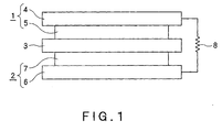
- Fig. 1 is a typical side view of a fuel cell in one embodiment of the present invention.
- a membrane electrode assembly (MEA) shown in Fig. 1 comprises an anode 1, a cathode 2, and a proton conductive film 3.
- the anode 1 comprises a diffusion layer 4 and an anode catalyst layer 5 stacked on the diffusion layer 4.
- the cathode 2 comprises a diffusion layer 6 and a cathode catalyst layer 7 stacked on the diffusion layer 6.
- the anode 1 and the cathode 2 are stacked on top of each other so that the anode catalyst layer 5 faces the cathode catalyst layer 7 through the proton conductive film 3.
- reference character 8 designates an external circuit.
- the anode catalyst layer contains the above catalyst.
- platinum (Pt) may be used in the cathode catalyst contained in the cathode catalyst layer.
- the cathode catalyst may be supported on a carrier.
- the cathode catalyst may be used in an unsupported form.
- An electroconductive porous sheet may be used in the diffusion layer.
- the electroconductive porous sheet may be, for example, a sheet formed of an air or liquid permeable material, for example, a carbon cloth or a carbon paper.
- the proton conductive material contained in the anode catalyst layer, the cathode catalyst layer, and the proton conductive film is not particularly limited so far as the material can conduct protons.
- Examples of proton conductive materials include, but not limited to, Nafion (manufactured by Du Pont (E.I.) de Nemours & Co.), Flemion (manufactured by Asahi Chemical Industry Co., Ltd.), Aciplex (manufactured by Asahi Glass Co., Ltd.) and other sulfonic acid group-containing fluororesins, and tungstic acid, phosphotungstic acid and other inorganic materials.
- a fuel cell in an embodiment of the present invention comprises the above MEA, means for supplying a fuel to an anode, and means for supplying an oxidizinig agent to a cathode.
- the number of MEAs may be one or at least two. The use of a plurality of MEAs can realize higher electromotive force.
- the fuel may be, for example, methanol, ethanol, formic acid, or an aqueous solution containing at least one material selected from methanol, ethanol, and formic acid.
- a carbon black carrier (tradename: Vulcan XC72, specific surface area: about 230 m 2 /g, manufactured by Cabot Corporation) was satisfactorily dispersed.
- the dispersed carrier was then placed in a holder provided in a champer in an ion beam sputter.
- the holder was evacuated. When the degree of vacuum reached not more than 3 ⁇ 10 -6 Torr, an Ar gas was allowed to flow into the champer.
- sputtering was carried out using a metal or an alloy as a target so as to provide various compositions as shown in Table 1 to deposit catalyst particles to the carrier.
- the product was acid cleaned with an aqueous sulfuric acid solution (10 g of sulfuric acid and 200 g of water), was then washed with water and was dried.
- a supported catalyst having the same composition as described in patent JP-A 2006-278217 was produced in the same manner as in a working example described in this reference.
- 500 mg of carbon black (tradename: Vulcan XC72, specific surface area: about 230 m 2 /g, manufactured by Cabot Corporation) was added 1000 ml of an ethanol solution containing a compound (content in the solution: 100 mg in terms of silicon), and the mixture was thoroughly stirred for even dispersion. Thereafter, the dispersion liquid was then heated under stirring to 55°C to evaporate and remove ethanol. Next, while allowing hydrogen gas to flow into the system at a rate of 50 ml/min, the residue obtained by the above method was heated at 300°C for 3 hr to support vanadium on carbon black.
- Each catalyst was subjected to XPS with Quantum-2000 (manufactured by PHI).
- a neutralization gun an electron gun, an argon gun
- Identification of peaks attributable to metal bond and oxygen bond is shown in Table 2.
- Si 2p spectrum was used, and a peak in a binding energy range of 99 to 100 eV was identified as attributable to a metal bond, and a peak in a binding energy of 103 to 104 eV was identified as attributable to an oxygen bond.
- the element T having the highest content is defined as a main element T.
- the results of measurement for a main element T (element T1 or element T2) for each catalyst are shown in Table 1.
- the peak area ratio of the main element T1 was defined as an oxygen bond-derived peak area obtained by presuming the metal bond-derived peak area of the same element to be 100%, and the peak area ratio of the main element T2 was defined as the metal bond-derived peak area by presuming the oxygen bond-derived peak area of the same element to be 100%.
- the average particle diameter of catalyst particles for each supported catalyst was measured for five desired different visual fields by observation under TEM. For each visual field, the diameters of 20 particles were measured, and the average of the diameters of the 100 particles in total was designated as the average particle diameter. The results are shown in Table 1 below.
- Examples 1 to 20 and Comparative Examples 1 to 19 were used as an anode catalyst in combination with a standard cathode electrode (a platinum (Pt) catalyst supported on carbon black, manufactured by Tanaka Kikinzoku Kogyo K.K.) to produce the following fuel cell electrodes, membrane electrode assemblies, and single cells which were then evaluated.
- a standard cathode electrode a platinum (Pt) catalyst supported on carbon black, manufactured by Tanaka Kikinzoku Kogyo K.K.
- the cathode electrode and the anode electrode each were cut off to a size of 3.2 ⁇ 3.2 cm square (electrode area 10 cm 2 ).
- Nafion 117 manufactured by Du Pont (E.I.)
- E.I. Du Pont
- thermocompression bonding under conditions of temperature 125°C, time 10 min and pressure 30 kg/cm 2 to produce a membrane electrode assembly.
- a single cell for a fuel direct supply-type polymer electrolyte fuel cell was produced by using this membrane electrode assembly and a passage plate.
- a 1 M aqueous methanol solution was supplied as a fuel into the anode cell in this single cell at a flow rate of 0.6 ml/min.
- air was supplied into the cathode electrode at a flow rate of 200 ml/min.
- discharge was carried out at a current density of 100 mA/cm 2 .
- the cell voltage was measured. The results are shown in Table 1 below.
- Example 1 to 20 As can be seen from the results shown in Table 1, a comparison of Examples 1 to 20 with Comparative Example 1 reveals that, as compared with the PtRu catalyst, the catalysts according to the present invention have a higher level of fuel cell properties and a stability comparable with the PtRu catalyst. A comparison of Example 1 to 20 with Comparative Examples 2 to 14 reveals that, when silicon or element T is added solely, a high level of fuel cell properties and a high level of stability could not be simultaneously realized.
- a comparison of Examples 1 and 2 with Comparative Examples 15 to 18 reveals that, when the addition amount of the silicon element is outside the range of 0.5 to 20 atomic%, or when the addition amount of the nickel (Ni) element is outside the range of 1 to 40 atomic%, a high level of activity and a high level of stability of not more than 1% in terms of percentage deterioration cannot be simultaneously realized. For other element systems, the same results could be obtained.
- a comparison of Example 1 with Comparative Example 19 reveals that, in order to realize a high level of activity, in addition to the composition, the regulation of the bound state of elements by the process is necessary.
Landscapes
- Chemical & Material Sciences (AREA)
- Chemical Kinetics & Catalysis (AREA)
- Electrochemistry (AREA)
- General Chemical & Material Sciences (AREA)
- Engineering & Computer Science (AREA)
- Materials Engineering (AREA)
- Life Sciences & Earth Sciences (AREA)
- Manufacturing & Machinery (AREA)
- Sustainable Development (AREA)
- Sustainable Energy (AREA)
- Inert Electrodes (AREA)
- Catalysts (AREA)
- Fuel Cell (AREA)
Abstract
PtxRuySizT1u
wherein T1 represents at least one element selected from the group consisting of nickel (Ni), tungsten (W), vanadium (V), and molybdenum (Mo); x = 30 to 90 atomic%; y = 0 to 50 atomic%; z = 0.5 to 20 atomic%; and u = 0.5 to 40 atomic%, or comprises a fine particle of a metal represented by formula:
PtxRuySizT2u
wherein T2 represents at least one element selected from the group consisting of hafnium (Hf), tin (Sn), zirconium (Zr), niobium (Nb), titanium (Ti), tantalum (Ta), chromium (Cr), and aluminum (Al); x = 30 to 90 atomic%; y = 0 to 50 atomic%; z = 0.5 to 20 atomic%; and u = 0.5 to 40 atomic%.
Description
- The present invention relates to a catalyst for a fuel cell, particularly a catalyst for a polymer solid electrolyte fuel cell, and a membrane electrode assembly and a fuel cell using the catalyst.
- Solid polymer fuel cells, particularly methanol-type solid polymer fuel cells using a methanol solution as a fuel, can be operated at a low temperature and can realize a reduction in size and a reduction in weight and thus have recently drawn attention as a power supply, for example, for mobile equipment, and research and development thereof have been forwarded.
- The performance of conventional fuel cells, however, is unsatisfactory for wide spreading. In fuel cells, chemical energy is converted to electric power by an electrode catalyst reaction, and high-activity catalysts are indispensable for the development of high-performance fuel cells.
- Up to now, PtRu has generally been used as a catalyst for an anode electrode in fuel cells. The voltage loss by the PtRu catalyst is about 0.3 V with respect to the theoretical voltage 1.21 V of the electrode catalyst reaction, and anode catalysts having a higher activity (methanol oxidation activity) than the catalytic activity of the PtRu have been desired. From this viewpoint, in order to improve the methanol oxidation activity of the PtRu catalyst, various studies, for example, on the addition of other elements to the PtRu, have been made.
- For example,
U.S. Patent No. 3,506,494 describes the effect attained by the addition of ten metals such as tungsten and tantalum, andJP-A 2006-278217 - On the other hand, the synthesis of catalysts by sputtering or vapor deposition is more advantageous than the solution method from the viewpoint of the control of the material. At the present time, however, the influence of a change in conditions such as the type of elements, catalyst composition, substrate material, and substrate temperature, on a catalyst production process has not been fully studied. Since the catalyst for fuel cells is nanoparticles, the surface electron state of catalyst particles and the nanostructure of the particles greatly depend upon the type and addition amount of elements added, and, thus, it is considered that, in order to realize high activity and high stability, the type of addition elements, the amount of elements added, and a combination of addition elements should be optimized. To this end, in PCT Publication No. 2005-532670, studies have been made on a production process by sputtering, and finding on elements other than Pt and Ru is described. Further,
JP-A 2006-128118 - In all the above prior art techniques, studies on the influence of the catalyst composition on the catalyst activity are unsatisfactory, and the provision of an improved catalyst for a fuel cell, which is excellent in both methanol oxidation activity and catalyst stability, has been still desired.
- In view of the above problems of the prior art, the present invention has been made, and an object of the present invention is to provide a catalyst for a fuel cell, which is excellent in both catalyst activity and catalyst stability.
- The above object can be attained by a catalyst for a fuel cell, comprising a metallic fine particle represented by formula:
PtxRuySizT1u
wherein T1 represents at least one element selected from the group consisting of nickel (Ni), tungsten (W), vanadium (V), and molybdenum (Mo); x = 30 to 90 atomic%; y = 0 to 50 atomic%; z = 0.5 to 20 atomic%; and u = 0.5 to 40 atomic%. - In a preferred embodiment of the present invention, the area of a peak attributable to an oxygen bond of silicon (Si) in a spectrum measured by X-ray photoelectron spectroscopy (XPS) is not more than 200% of the area of a peak attributable to a metal bond of a silicon element. More preferably, the area of a peak attributable to an oxygen bond of the element T1 in a spectrum measured by X-ray photoelectron spectroscopy (XPS) is not more than 200% of the area of a peak attributable to a metal bond of the same element.
- According to the present invention, there is provided a catalyst for a fuel cell, comprising a metallic fine particle represented by formula:
PtxRuySizT2u
wherein T2 represents at least one element selected from the group consisting of hafnium (Hf), tin (Sn), zirconium (Zr), niobium (Nb), titanium (Ti), tantalum (Ta), chromium (Cr), and aluminum (AI); x = 30 to 90 atomic%; y = 0 to 50 atomic%; z = 0.5 to 20 atomic%; and u = 0.5 to 40 atomic%. - In the above embodiment, preferably, the area of a peak attributable to an oxygen bond of silicon (Si) in a spectrum measured by X-ray photoelectron spectroscopy (XPS) is not more than 200% of the area of a peak attributable to a metal bond of a silicon element, or the area of a peak attributable to a metal bond of the element T2 in a spectrum measured by X-ray photoelectron spectroscopy (XPS) is not more than 200% of the area of a peak attributable to an oxygen bond of the same element.
- The present invention includes a supported catalyst for a fuel cell, comprising a carrier and the above catalyst supported on the carrier, a membrane electrode assembly comprising the supported catalyst, and a fuel cell comprising the membrane electrode assembly.
- The present invention can provide a catalyst for a fuel cell, which is excellent in both catalyst activity and catalyst stability.
-
-
Fig. 1 is a typical side view of a fuel cell in one embodiment of the present invention. - As described above, the catalyst for a fuel cell according to the first invention comprises a metallic fine particle represented by formula:
PtxRuySizT1u
wherein T1 represents at least one element selected from the group consisting of nickel (Ni), tungsten (W), vanadium (V), and molybdenum (Mo); x = 30 to 90 atomic%; y = 0 to 50 atomic%; z = 0.5 to 20 atomic%; and u = 0.5 to 40 atomic%. - The catalyst for a fuel cell according to the second invention comprises a metallic fine particle represented by formula:
PtxRuySizT2u
wherein T2 represents at least one element selected from the group consisting of hafnium (Hf), tin (Sn), zirconium (Zr), niobium (Nb), titanium (Ti), tantalum (Ta), chromium (Cr), and aluminum (AI); x = 30 to 90 atomic%; y = 0 to 50 atomic%; z = 0.5 to 20 atomic%; and u = 0.5 to 40 atomic%. - Thus the present invention is characterized in that silicon and an element T have been added in combination to a specific noble metal and, at the same time, the content ratio of the these elements has been limited to a specific range. As shown in the results of Examples and Comparative Examples which will be described later, a combination of the composition and the content ratio could have realized the provision of a catalyst for a fuel cell, which is excellent in both catalyst activity and catalyst stability.
- The present invention will be described in conjunction with preferred embodiments.
- In the catalyst according to the present invention, platinum (Pt) is a main catalyst element. Platinum is very effective for the oxidation of hydrogen and a dehydrogenation reaction of an organic fuel. When the amount of the platinum is excessively small, the catalyst activity is lowered. Accordingly, in the above formula, the content x of Pt is preferably 30 to 90 atomic%, more preferably 40 to 85 atomic%. Ruthenium (Ru) is effective for the suppression of CO poisoning, and the content y of ruthenium is preferably 0 to 50 atomic%, more preferably 0 to 45 atomic%. In the catalyst of the present invention, even when the content of ruthenium is low or zero, satisfactory catalyst activity can be obtained. Further, replacement of a part of platinum with other metal sometimes improves the activity. Since the noble metal has excellent chemical stability, when replacement is contemplated, replacement, for example, with rhodium (Rh), osmium (Os), or iridium (Ir) is preferred.
- In the present invention, silicon, and element T1 or element T2 (the elements T1 and T2 being hereinafter collectively referred to as element T) function as a cocatalyst. Element T is at least one element selected from the group consisting of nickel (Ni), tungsten (W), vanadium (V), hafnium (Hf), tin (Sn), zirconium (Zr), niobium (Nb), molybdenum (Mo), titanium (Ti), tantalum (Ta), chromium (Cr), and aluminum (AI). In the present invention, as described above, it was found that, when silicon and element T are added in combination to the Pt-Ru-based component, the combination can improve both activity and stability to a high level in a good balance.
- The mechanism through which the activity is enhanced, has not been fully elucidated yet. However, in the combination in a specific composition, it is considered that the participation of the coexistence of a silicon element, an element T and a noble metal is important in the enhanced activity, and it is further considered that the nanostructure, surface structure, and electron state of catalyst fine particles attributable to the coexistence can render the catalyst activity high.
- From this viewpoint, regarding silicon, the area of the peak attributable to an oxygen bond of silicon in the catalyst is preferably not more than 200% of the area of the peak attributable to the metal bond of the silicon element, particularly preferably not more than 150%, most preferably not more than 80%. When the area ratio in this case exceeds 200%, the catalyst activity is disadvantageously significantly lowered.
- Also for element T, from the viewpoint of simultaneously realizing both high activity and high stability in a good balance, it is important that the element T be in a proper state of element. From this viewpoint, for element T1 (Ni, W, V, or Mo element), the area of the peak attributable to the oxygen bond of the same element in a spectrum as measured by X-ray photoelectron spectroscopy (XPS) is preferably not more than 200% of the area of the peak attributable to the metal bond of the same element, particularly preferably not more than 120%, most preferably not more than 80%. Further, for element T2 (Sn, Hf, Zr, Nb, Ti, Ta, Cr, or Al element), the area of the peak attributable to the metal bond in a spectrum as measured by X-ray photoelectron spectroscopy (XPS) is preferably not more than 200% of the area of the peak attributable to the oxygen bond of the same element, particularly preferably not more than 120%, most preferably not more than 80%. In both the cases, bringing the area ratio to not more than 200% can improve the catalyst activity or stability.
- In the present invention, the term "peak area" as used herein refers to the integral value of a binding energy axis of a part obtained by subtracting a signal background from a peak attributable to the element in the XPS spectrum. When there is an overlap of peaks, the area of the peak belonging to the element can be determined by conducting peak separation.
- Further, in the present invention, the content z of silicon in the catalyst is preferably 0.5 to 20 atomic%, more preferably 1 to 15 atomic%. When the Si content is less than 0.5 atomic%, the cocatalyst action of silicon is insufficient. On the other hand, when the Si content exceeds 20 atomic%, the number of major active sites constituted by the platinum and ruthenium atoms is significantly reduced resulting in lowered catalyst activity.
- Furthermore, in the present invention, the content u of element T in the catalyst is preferably 0.5 to 40 atomic%, more preferably 1 to 30 atomic%, most preferably 1 to 20 atomic%. When the content u of element T is outside the range of 0.5 to 40 atomic%, the catalyst activity and the stability cannot be simultaneously realized without difficulties.
- When tin (Sn) is contained, the Sn content is preferably in the range of 0.5 to 10 atomic%, most preferably 1 to 8 atomic%. When the Sn content is less than 0.5 atomic% or more than 10 atomic%, the cocatalyst activity of tin is lowered.
- In the catalyst according to the present invention, metal elements other than described above, particularly, at least one metal selected from manganese (Mn), iron (Fe), cobalt (Co), gold (Au) and copper (Cu) can be additionally added. The addition of these metal elements in combination sometimes contributes to an improvement in activity. The addition amount is preferably in the range of 2 to 20 atomic%.
- Further, in the catalyst according to the present invention, oxygen can be contained. In the course of the synthesis process, metal components of the catalyst surface are unavoidably oxidized by the adsorption of oxygen on the surface of the catalyst in storing the catalyst, or by surface oxidation treatment such as acid washing. In the present invention, however, it was found that the production of a small amount of oxide on the surface can improve the activity and stability of the catalyst. Accordingly, in the present invention, the presence of the oxide is positively accepted. From this viewpoint, the content of oxygen in the catalyst according to the present invention is preferably not more than 15 atomic%. When the content of oxygen in the catalyst exceeds 15 atomic%, the catalyst activity is adversely affected.
- In the catalyst according to the present invention, the presence of not more than 0.1 atomic% of impurity elements, for example, phosphorus (P), sulfur (S), and chlorine (Cl) is tolerable. There is a possibility that these elements are included during the production of the catalyst or membrane electrode assembly, or during the treatment process. It is considered that, when the content of these elements is not more than 0.1 atomic%, the properties of the catalyst according to the present invention are not significantly deteriorated. Also from this viewpoint, it can be said that the level of the acceptability of the surface structure of the catalyst according to the present invention is high.
- The particle diameter of the catalyst according to the present invention is not particularly limited. When the particles are nano fine particles, the highest activity can be realized. Accordingly, the average particle diameter of the catalyst particles according to the present invention is preferably not more than 10 nm. This is because, when the average particle diameter of the catalyst particles is not more than 10 nm, the active efficiency of the catalyst can be improved. The average particle diameter is more preferably in the range of 0.5 to 10 nm. An average particle diameter of not less than 0.5 nm facilitates the regulation of the catalyst synthesis process and is also advantageous in cost.
- Fine particles having an average particle diameter of not more than 10 nm may be used solely as the catalyst particles. Alternatively, aggregates (secondary particles) of primary particles formed of the fine particles may also be used.
- The present invention embraces the form of a supported catalyst comprising the above catalyst supported on a carrier. In this case, the carrier may be an electroconductive carrier. For example, carbon black may be mentioned as the electroconductive carrier. The electroconductive carrier, however, is not limited to carbon black, and any conventional carrier may be properly used so far as the carrier has excellent electroconductivity and stability. In recent years, nanocarbon materials, for example, fiber-, tube-, or coil-shaped nanocarbon materials have been developed. The activity is possibly further improved by supporting catalyst particles to be used in the present invention on these materials having different surface states. Carriers other than carbon materials usable herein include electroconductive ceramic materials. In this case, a further synergistic effect can be expected by the ceramic carrier and the catalyst particles.
- Next, the production process of a supported catalyst according to the present invention will be described. The supported catalyst according to the present invention may be produced, for example, by sputtering or vapor deposition. As compared with solution methods such as impregnation methods, precipitation methods, or colloid methods, these methods can more easily produce catalysts having a metal bond-containing specific mixed state. The supported catalyst according to the present invention cannot be produced by conventional solution methods without difficulties. In a method, which comprises preparing a metal bond-containing polynuclear complex of Pt and Ru with T, impregnating a carrier with the polynuclear complex, and subjecting the impregnation product to reduction treatment, the synthesis of the polynuclear complex is difficult making it impossible to produce the supported catalyst according to the present invention. Further, the production cost would be increased. When the supported catalyst according to the present invention is produced by electrodeposition or electrophoresis, the control of nanoparticles is difficult and, thus, this method is expected to be disadvantageous in production cost. In sputtering or vapor deposition, an alloy target may be used. Alternatively, simultaneous sputtering or simultaneous vapor deposition may be carried out using metal targets of respective constituent elements.
- A method for depositing catalyst particles on an electroconductive carrier by sputtering will be described. A particulate or fibrous electroconductive carrier is first satisfactorily dispersed. The dispersed carrier is then inserted in a holder provided in a champer of a sputtering device, and, while stirring in a predetermined direction, constituent metals of the catalyst is deposited on the carrier by sputtering. The temperature of the carrier during sputtering is preferably set at a temperature of 400°C or below. When the setting temperature is excessively high, phase separation is likely to occur in catalyst particles and, consequently, the catalyst activity sometimes becomes unstable. The lower limit of the carrier temperature is preferably 10°C from the viewpoint of reducing the cost necessary for cooling the carrier. The temperature of the carrier may be measured with a thermocouple. Further, stirring is important for realizing even deposition of the catalyst. When stirring is not carried out, the properties of the fuel cell are deteriorated due to uneven catalyst distribution.
- The catalyst according to the present invention may also be produced by sputtering directly on an electroconductive carbon fiber-containing porous paper, an electrode diffusion layer, or an electrolyte film. In this case, the catalyst should be formed in the form of nano fine particles by regulating the process. Further, as in the above embodiment, preferably, the temperature of the porous paper is brought to 400°C or below. In some cases, the activity can be further improved by a method in which, after the formation of catalyst particles by sputtering or vapor deposition, the catalyst particles are subjected to acid washing treatment, alkali treatment or heat treatment. The reason why the activity can be increased by this method is believed to reside in that the catalyst structure or surface structure is rendered more proper by the acid washing treatment, alkali treatment, or heat treatment. In the acid washing treatment, the use of an aqueous acid solution suffices for contemplated results. Preferably, however, an aqueous sulfuric acid solution is used. An aqueous alkali solution may be used for the alkali treatment. The heat treatment is preferably carried out at a temperature of 10 to 400°C in an atmosphere of an oxygen partial pressure of less than 5%. Further, since fine particles are likely to be formed, other materials such as carbon material and constituent metal elements may be sputtered or vapor deposited simultaneously. In the present invention, a method may be adopted in which a method having high solubility, for example, copper (Cu) or zinc (Zn), and constituent metal elements may be sputtered or vapor deposited simultaneously followed by acid washing or the like to remove copper, zinc and the like.
- The present invention includes a membrane electrode assembly comprising the above supported catalyst. The membrane electrode assembly (MEA) in a preferred embodiment of the present invention comprises an anode, a cathode, and a proton conductive film disposed between the anode and the cathode.
- Further, the fuel cell in an embodiment of the present invention may comprise the above membrane electrode assembly.
-
Fig. 1 is a typical side view of a fuel cell in one embodiment of the present invention. - A membrane electrode assembly (MEA) shown in
Fig. 1 comprises an anode 1, acathode 2, and a protonconductive film 3. The anode 1 comprises adiffusion layer 4 and ananode catalyst layer 5 stacked on thediffusion layer 4. Thecathode 2 comprises a diffusion layer 6 and a cathode catalyst layer 7 stacked on the diffusion layer 6. The anode 1 and thecathode 2 are stacked on top of each other so that theanode catalyst layer 5 faces the cathode catalyst layer 7 through the protonconductive film 3. InFig. 1 , reference character 8 designates an external circuit. - The anode catalyst layer contains the above catalyst. On the other hand, for example, platinum (Pt) may be used in the cathode catalyst contained in the cathode catalyst layer. The cathode catalyst may be supported on a carrier. Alternatively, the cathode catalyst may be used in an unsupported form. An electroconductive porous sheet may be used in the diffusion layer. The electroconductive porous sheet may be, for example, a sheet formed of an air or liquid permeable material, for example, a carbon cloth or a carbon paper.
- The proton conductive material contained in the anode catalyst layer, the cathode catalyst layer, and the proton conductive film is not particularly limited so far as the material can conduct protons. Examples of proton conductive materials include, but not limited to, Nafion (manufactured by Du Pont (E.I.) de Nemours & Co.), Flemion (manufactured by Asahi Chemical Industry Co., Ltd.), Aciplex (manufactured by Asahi Glass Co., Ltd.) and other sulfonic acid group-containing fluororesins, and tungstic acid, phosphotungstic acid and other inorganic materials.
- A fuel cell in an embodiment of the present invention comprises the above MEA, means for supplying a fuel to an anode, and means for supplying an oxidizinig agent to a cathode. The number of MEAs may be one or at least two. The use of a plurality of MEAs can realize higher electromotive force. The fuel may be, for example, methanol, ethanol, formic acid, or an aqueous solution containing at least one material selected from methanol, ethanol, and formic acid.
- The following Examples and Comparative Examples further illustrate the present invention.
- A carbon black carrier (tradename: Vulcan XC72, specific surface area: about 230 m2/g, manufactured by Cabot Corporation) was satisfactorily dispersed. The dispersed carrier was then placed in a holder provided in a champer in an ion beam sputter. The holder was evacuated. When the degree of vacuum reached not more than 3 × 10⁻⁶ Torr, an Ar gas was allowed to flow into the champer. While stirring the carrier in such a state kept at 400°C or below, sputtering was carried out using a metal or an alloy as a target so as to provide various compositions as shown in Table 1 to deposit catalyst particles to the carrier. The product was acid cleaned with an aqueous sulfuric acid solution (10 g of sulfuric acid and 200 g of water), was then washed with water and was dried.
- A supported catalyst having the same composition as described in patent
JP-A 2006-278217 - Next, 300 ml of a cyclohexane solution containing 1,5-cyclooctadienedimethylplatinum in an amount of 317.7 mg in terms of platinum metal, and 40 ml of an ethanol solution containing ruthenium chloride in an amount of 82.3 mg in terms of a ruthenium metal were mixed together. The above silicon-supported carbon was added to the mixed solution, and the mixture was thoroughly stirred for even dispersion. The dispersion was heated to 55°C with stirring to evaporate and remove the solvent. Next, while allowing hydrogen gas to flow at a rate of 50 ml/min, the residue obtained by the above method was heated at 300°C for 3 hr to support platinum, ruthenium and silicon on carbon black and thus to give supported catalysts.
- Each catalyst was subjected to XPS with Quantum-2000 (manufactured by PHI). A neutralization gun (an electron gun, an argon gun) was used for charge-up compensation and charge correction (Cls: C - C = 284.6 eV). For each element, identification of peaks attributable to metal bond and oxygen bond is shown in Table 2. For example, for a silicon element, an Si 2p spectrum was used, and a peak in a binding energy range of 99 to 100 eV was identified as attributable to a metal bond, and a peak in a binding energy of 103 to 104 eV was identified as attributable to an oxygen bond. When a plurality of types of element T are contained in the catalyst particle, the element T having the highest content is defined as a main element T. The results of measurement for a main element T (element T1 or element T2) for each catalyst are shown in Table 1.
- The peak area ratio of the main element T1 was defined as an oxygen bond-derived peak area obtained by presuming the metal bond-derived peak area of the same element to be 100%, and the peak area ratio of the main element T2 was defined as the metal bond-derived peak area by presuming the oxygen bond-derived peak area of the same element to be 100%.
- As shown in Table 1, it was confirmed that the oxygen bond-derived peak area of each main element T1 on an XPS spectrum in Examples 1 to 20 was not more than 200% of the metal bond-derived peak area of the same element, and the metal bond-derived peak area of each main element T2 was not more than 200% of the oxygen bond-derived peak area of the same element. It was found that the silicon element of Comparative Example 19 prepared by the solution method was substantially in an oxidized state. The above sample for the measurement is a catalyst which has been washed with an acid. The catalyst before the acid washing sometimes has a higher oxidization bond-derived peak than the acid washed catalyst. This is in many cases due to an unstable oxide layer, and it was confirmed that, when the acid washing process was not carried out, spontaneous conversion to a stable layer during power generation was observed, and the area ratio of the oxidization bond-derived peak was on the same level as the acid washed catalyst.
- The average particle diameter of catalyst particles for each supported catalyst was measured for five desired different visual fields by observation under TEM. For each visual field, the diameters of 20 particles were measured, and the average of the diameters of the 100 particles in total was designated as the average particle diameter. The results are shown in Table 1 below.
- The products of Examples 1 to 20 and Comparative Examples 1 to 19 were used as an anode catalyst in combination with a standard cathode electrode (a platinum (Pt) catalyst supported on carbon black, manufactured by Tanaka Kikinzoku Kogyo K.K.) to produce the following fuel cell electrodes, membrane electrode assemblies, and single cells which were then evaluated.
- Various catalysts obtained above (3 g) were weighed. Each of the supported catalyst, together with 8 g of pure water, 15 g of a 20% Nafion solution, and 30 g of 2-ethoxyethanol, was thoroughly stirred and was dispersed to prepare slurries. The slurry was coated by a control coater on carbon paper subjected to treatment rendering the paper water repellent (350 µm, manufactured by Toray Industries, Inc.), and the coated paper was dried to produce an anode electrode of which the loading density of the noble metal catalyst was 1 mg/cm2.
- A platinum (Pt) catalyst (2 g) manufactured by Tanaka Kikinzoku Kogyo K.K. was first weighed. The weighted catalyst, together with 5 g of pure water, 5 g of a 20% Nafion solution, and 20 g of 2-ethoxyethanol, was thoroughly stirred and was dispersed to prepare slurries. The slurry was coated by a control coater on carbon paper subjected to treatment rendering the paper water repellent (350 µm, manufactured by Toray Industries, Inc.), and the coated paper was dried to produce a cathode electrode of which the loading density of the noble metal catalyst was 2 mg/cm2.
- The cathode electrode and the anode electrode each were cut off to a size of 3.2 × 3.2 cm square (electrode area 10 cm2). Nafion 117 (manufactured by Du Pont (E.I.)) as a proton conductive solid polymer film was held between the cathode electrode and the anode electrode followed by thermocompression bonding under conditions of temperature 125°C, time 10 min and pressure 30 kg/cm2 to produce a membrane electrode assembly.
- A single cell for a fuel direct supply-type polymer electrolyte fuel cell was produced by using this membrane electrode assembly and a passage plate. A 1 M aqueous methanol solution was supplied as a fuel into the anode cell in this single cell at a flow rate of 0.6 ml/min. At the same time, air was supplied into the cathode electrode at a flow rate of 200 ml/min. In such a state that the cell was maintained at 50°C, discharge was carried out at a current density of 100 mA/cm2. Thirty min after the initiation of the discharge, the cell voltage was measured. The results are shown in Table 1 below. Regarding the high level of stability, power generation of the single cell was carried out under the above operating conditions for 500 hr for evaluation of the single cell using the percentage lowering in voltage at a current density of 100 mA/cm2 as an index. The results are shown in Table 1 below.
- As can be seen from the results shown in Table 1, a comparison of Examples 1 to 20 with Comparative Example 1 reveals that, as compared with the PtRu catalyst, the catalysts according to the present invention have a higher level of fuel cell properties and a stability comparable with the PtRu catalyst. A comparison of Example 1 to 20 with Comparative Examples 2 to 14 reveals that, when silicon or element T is added solely, a high level of fuel cell properties and a high level of stability could not be simultaneously realized. A comparison of Examples 1 and 2 with Comparative Examples 15 to 18 reveals that, when the addition amount of the silicon element is outside the range of 0.5 to 20 atomic%, or when the addition amount of the nickel (Ni) element is outside the range of 1 to 40 atomic%, a high level of activity and a high level of stability of not more than 1% in terms of percentage deterioration cannot be simultaneously realized. For other element systems, the same results could be obtained. A comparison of Example 1 with Comparative Example 19 reveals that, in order to realize a high level of activity, in addition to the composition, the regulation of the bound state of elements by the process is necessary.
- It was confirmed that the same tendency as described above was observed in a reformed gas-type polymer electrolyte fuel cell using the catalyst according to the present invention. Accordingly, also for CO poisoning, the catalysts of the present invention is more effective than the conventional Pt-Ru catalyst.
Table 1 Catalyst composition Si peak area ratio (%) (1) Main element T1 area area ratio A (%) (2) Main element T2 ratio B (%) (3) Voltage (V) Deteri-oration rate (%) Ex. 1 Pt40Ru30Si10Ni20 About 20 - 0.50 0.9 Ex. 2 Pt44Ru40Si1Ni15 < 20 20 - 0.49 0.7 Ex. 3 Pt50Ru41Si3W6 < 20 20 - 0.48 0.7 Ex. 4 Pt90Si5V5 About 40 - 0.46 0.6 Ex. 5 Pt50Ru42Si3Mo5 About 30 - 0.47 0.8 Ex.6 Pt50Ru40Si5Sn5 About - 30 0.48 0.9 Ex.7 Pt40Ru37Si20Zr3 160 - 40 0.46 0.7 Ex. 8 Pt44Ru43Si8Nb5 50 - 40 0.47 0.6 Ex. 9 Pt50Ru42Si3Hf5 < 20 - 30 0.48 0.6 Ex. 10 Pt50Ru41Si3Ti6 < 20 - 30 0.47 0.7 Ex. 11 Pt50Ru37Si10Ta3 About - 40 0.48 0.8 Ex. 12 Pt50Ru40Si5Cr5 About - 40 0.47 0.6 Ex. 13 Pt50Ru39Si10Al1 About - 50 0.47 0.7 Ex. 14 Pt30Ru50Si0.5Ni15Al2 < 20 20 40 0.50 0.7 Ex. 15 Pt50Ru27Si3W15Nb5 About 60 30 0.48 0.6 Ex. 16 Pt44Ru45Si1W4Cr6 < 20 30 40 0.48 0.8 Ex. 17 Pt50Ru35Si3V15Nb7 About 40 40 0.49 0.9 Ex. 18 Pt45Ru40Si5V6Zr4 < 20 40 50 0.50 0.7 Ex. 19 Pt60Ru30Si1Hf4Nb5 < 20 - 40 0.49 0.6 Ex. 20 Pt44Ru15Si1Sn5W20Ni15 < 20 30 30 0.51 0.6 Comp. Ex. 1 Pt50Ru50 - - - 0.42 0.5 Comp. Ex. 2 Pt50Ru40Si10 < 30 - - 0.43 2 Comp. Ex. 3 Pt45Ru35Ni20 - 20 - 0.44 2 Comp. Ex. 4 Pt50Ru44W6 - 30 - 0.43 2 Comp. Ex. 5 Pt60Ru33V7 - 20 - 0.43 1.5 Comp. Ex. 6 Pt48Ru47Mo5 - 30 - 0.35 2 Comp. Ex. 7 Pt50Ru45Sn5 - - 30 0.45 2 Comp. Ex. 8 Pt40Ru37Zr3 - - 20 0.30 1.5 Comp. Ex. 9 Pt50Ru45Nb5 - - 30 0.40 0.6 Comp. Ex. 10 Pt50Ru47Hf5 - - 30 0.43 2 Comp. Ex. 11 Pt50Ru44Ti6 - - 40 0.37 4 Comp. Ex. 12 Pt50Ru47Ta3 - - 40 0.35 2 Comp. Ex. 13 Pt50Ru45Cr5 - - 40 0.34 0.8 Comp. Ex. 14 Pt50Ru49Al1 - - 40 0.44 1.0 Comp. Ex. 15 Pt35Ru20Si0.2Ni44.8 < 20 20 - 0.43 2.0 Comp. Ex. 16 Pt60Ru10Si10Ni20 < 20 20 - 0.39 1.0 Comp. Ex. 17 Pt20Ru50Si10Ni20 < 20 20 - 0.30 1.5 Comp. Ex. 18 Pt50Ru35Si25Ni10 <20 20 - 0.41 1.3 Comp. Ex. 19 Pt74Ru25Si3 (Solution method) Only oxygen bond - - 0.37 0.8 (1): Ratio between Si oxidization bond-derived peak and metal bond-derived peak of the same element
(2): Ratio between oxidization bond-derived peak of element T1 (T1 = Ni, W, V, or Mo) and metal bond-derived peak of the same element
(3): Ratio between metal bond-derived peak of element T2 (T2 = Sn, Hf, Zr, Nb, Mo, Ti, Ta, or Cr) and oxygen bond-derived peak of the same element.Table 2 Element Range of presence of metal bond-derived peak (eV) Range of presence of oxygen bond-derived peak (eV) Si 99- 100 (2p) 103 - 104 (2p) V 512 - 513 (2p 3/2) 516 - 517 (2p 3/2) W 31ev - 34ev (4f 7/2) 36 - 40 (4f 5/2) Mo 227 - 228 (3d 5/2) 235 - 237 (3d 5/2) Nb 202 - 203 (3d 5/2) 202 - 203 (3d 5/2) NbO: 203 - 205 (3d 3/2) Nb2O5: 209 - 211 (3d 5/2) Cr 574 (2p 3/2) 576 - 580 (2p 3/2) Zr 178 - 179 (3d 5/2) ZrO2: 184 - 185 (3d 3/2) Ti 454 (2p 3/2) TiO: 455 (2p 3/2), TiO2: 459 (due to overlapping with Ru, there is a high possibility of being unobservable) Ta 23 - 24 (4f 7/2) 27 - 29 (4f 5/2) Al 117-118 (2s) 120-121 (2s) Sn 493 - 494 (3d 3/2) 494 - 496 (3d 3/2) Hf 14 - 15 (4f 7/2) 17 - 19 (4f 5/2) - Additional advantages and modifications will readily occur to those skilled in the art. Therefore, the invention in its broader aspects is not limited to the specific details and representative embodiments shown and described herein. Accordingly, various modifications may be made without departing from the spirit or scope of the general inventive concept as defined by the appended claims and their equivalents.
Claims (17)
- A catalyst for a fuel cell, comprising a fine particle of a metal represented by formula:
PtxRuySizT1u
wherein T1 represents at least one element selected from the group consisting of nickel (Ni), tungsten (W), vanadium (V), and molybdenum (Mo); x = 30 to 90 atomic%; y = 0 to 50 atomic%; z = 0.5 to 20 atomic%; and u = 0.5 to 40 atomic%. - The catalyst for a fuel cell according to claim 1, wherein the area of a peak attributable to an oxygen bond of silicon (Si) in a spectrum measured by X-ray photoelectron spectroscopy (XPS) is not more than 200% of the area of a peak attributable to a metal bond of a silicon element.
- The catalyst for a fuel cell according to claim 1, wherein the area of a peak attributable to an oxygen bond of the element T1 in a spectrum measured by X-ray photoelectron spectroscopy (XPS) is not more than 200% of the area of a peak attributable to a metal bond of the same element.
- The catalyst for a fuel cell according to claim 1, wherein x = 30 to 90 atomic%.
- The catalyst for a fuel cell according to claim 1, wherein y = 0 to 45 atomic%.
- The catalyst for a fuel cell according to claim 1, wherein z = 1 to 15 atomic%.
- The catalyst for a fuel cell according to claim 1, wherein u = 1 to 30 atomic%.
- A catalyst for a fuel cell, comprising a fine particle of a metal represented by formula:
PtxRuySizT2u
wherein T2 represents at least one element selected from the group consisting of hafnium (Hf), tin (Sn), zirconium (Zr), niobium (Nb), titanium (Ti), tantalum (Ta), chromium (Cr), and aluminum (Al); x = 30 to 90 atomic%; y = 0 to 50 atomic%; z = 0.5 to 20 atomic%; and u = 0.5 to 40 atomic%. - The catalyst for a fuel cell according to claim 8, wherein the area of a peak attributable to an oxygen bond of silicon in a spectrum measured by X-ray photoelectron spectroscopy (XPS) is not more than 200% of the area of a peak attributable to a metal bond of a silicon element.
- The catalyst for a fuel cell according to claim 8, wherein the area of a peak attributable to a metal bond of the element T2 in a spectrum measured by X-ray photoelectron spectroscopy (XPS) is not more than 200% of the area of a peak attributable to an oxygen bond of the same element.
- The catalyst for a fuel cell according to claim 8, wherein x = 30 to 90 atomic%.
- The catalyst for a fuel cell according to claim 8, wherein y = 0 to 45 atomic%.
- The catalyst for a fuel cell according to claim 8, wherein z = 1 to 15 atomic%.
- The catalyst for a fuel cell according to claim 8, wherein u = 1 to 30 atomic%.
- A supported catalyst for a fuel cell, comprising a carrier and a catalyst according to claim 1 or 8 supported on the carrier.
- A membrane electrode assembly comprising a supported catalyst according to claim 15.
- A fuel cell comprising a membrane electrode assembly according to claim 16.
Applications Claiming Priority (1)
| Application Number | Priority Date | Filing Date | Title |
|---|---|---|---|
| JP2007082185A JP4374036B2 (en) | 2007-03-27 | 2007-03-27 | Polymer solid oxide fuel cell catalyst, membrane electrode assembly and fuel cell |
Publications (1)
| Publication Number | Publication Date |
|---|---|
| EP1976044A1 true EP1976044A1 (en) | 2008-10-01 |
Family
ID=39523265
Family Applications (1)
| Application Number | Title | Priority Date | Filing Date |
|---|---|---|---|
| EP08250915A Withdrawn EP1976044A1 (en) | 2007-03-27 | 2008-03-17 | Catalyst for polymer solid electrolyte fuel cell, membrane electrode assembly, and fuel cell |
Country Status (4)
| Country | Link |
|---|---|
| US (1) | US8080347B2 (en) |
| EP (1) | EP1976044A1 (en) |
| JP (1) | JP4374036B2 (en) |
| KR (1) | KR20080087665A (en) |
Families Citing this family (7)
| Publication number | Priority date | Publication date | Assignee | Title |
|---|---|---|---|---|
| JP5205013B2 (en) * | 2007-08-31 | 2013-06-05 | 株式会社東芝 | Anode for fuel cell and fuel cell using the same |
| JP5032250B2 (en) * | 2007-09-21 | 2012-09-26 | 株式会社東芝 | Methanol oxidation catalyst and method for producing the same |
| JP5032251B2 (en) * | 2007-09-21 | 2012-09-26 | 株式会社東芝 | Methanol oxidation catalyst and method for producing the same |
| JP5314910B2 (en) * | 2008-03-26 | 2013-10-16 | 株式会社東芝 | Methanol oxidation catalyst and method for producing the same |
| JP2009238569A (en) | 2008-03-27 | 2009-10-15 | Toshiba Corp | Catalyst for fuel cell, its manufacturing method, membrane electrode assembly and fuel cell using its catalyst |
| US8737989B2 (en) * | 2008-08-29 | 2014-05-27 | Apple Inc. | Methods and apparatus for machine-to-machine based communication service classes |
| RU2479076C1 (en) * | 2012-03-05 | 2013-04-10 | Федеральное государственное бюджетное учреждение науки Институт высокотемпературной электрохимии Уральского отделения Российской Академии наук | Solid electrolyte based on hafnium oxide |
Citations (5)
| Publication number | Priority date | Publication date | Assignee | Title |
|---|---|---|---|---|
| US3506494A (en) | 1966-12-22 | 1970-04-14 | Engelhard Ind Inc | Process for producing electrical energy utilizing platinum-containing catalysts |
| US5872074A (en) * | 1997-01-24 | 1999-02-16 | Hydro-Quebec | Leached nanocrystalline materials process for manufacture of the same, and use thereof in the energetic field |
| WO2005119828A2 (en) | 2004-05-27 | 2005-12-15 | E.I. Dupont De Nemours And Company | Sol-gel derived composites comprising oxide or oxyhydroxide matrices with noble metal components and carbon for fuel cell catalysts |
| JP2006128118A (en) | 2004-10-28 | 2006-05-18 | Samsung Sdi Co Ltd | Catalyst for fuel cell, method for producing the same, and fuel cell system including the same |
| JP2006278217A (en) | 2005-03-30 | 2006-10-12 | Hitachi Maxell Ltd | Fuel cell and membrane electrode assembly |
Family Cites Families (3)
| Publication number | Priority date | Publication date | Assignee | Title |
|---|---|---|---|---|
| JP2005532670A (en) | 2002-07-01 | 2005-10-27 | イー・アイ・デュポン・ドウ・ヌムール・アンド・カンパニー | Deposition catalyst and its use in fuel cells |
| JP2004079244A (en) * | 2002-08-12 | 2004-03-11 | Toshiba Corp | Fuel cell catalyst and fuel cell |
| JP4713959B2 (en) * | 2005-06-23 | 2011-06-29 | 株式会社東芝 | Fuel cell supported catalyst and fuel cell |
-
2007
- 2007-03-27 JP JP2007082185A patent/JP4374036B2/en not_active Expired - Fee Related
-
2008
- 2008-03-06 KR KR1020080020866A patent/KR20080087665A/en not_active Ceased
- 2008-03-17 EP EP08250915A patent/EP1976044A1/en not_active Withdrawn
- 2008-03-17 US US12/049,739 patent/US8080347B2/en not_active Expired - Fee Related
Patent Citations (5)
| Publication number | Priority date | Publication date | Assignee | Title |
|---|---|---|---|---|
| US3506494A (en) | 1966-12-22 | 1970-04-14 | Engelhard Ind Inc | Process for producing electrical energy utilizing platinum-containing catalysts |
| US5872074A (en) * | 1997-01-24 | 1999-02-16 | Hydro-Quebec | Leached nanocrystalline materials process for manufacture of the same, and use thereof in the energetic field |
| WO2005119828A2 (en) | 2004-05-27 | 2005-12-15 | E.I. Dupont De Nemours And Company | Sol-gel derived composites comprising oxide or oxyhydroxide matrices with noble metal components and carbon for fuel cell catalysts |
| JP2006128118A (en) | 2004-10-28 | 2006-05-18 | Samsung Sdi Co Ltd | Catalyst for fuel cell, method for producing the same, and fuel cell system including the same |
| JP2006278217A (en) | 2005-03-30 | 2006-10-12 | Hitachi Maxell Ltd | Fuel cell and membrane electrode assembly |
Also Published As
| Publication number | Publication date |
|---|---|
| JP4374036B2 (en) | 2009-12-02 |
| US20080241639A1 (en) | 2008-10-02 |
| KR20080087665A (en) | 2008-10-01 |
| US8080347B2 (en) | 2011-12-20 |
| JP2008243577A (en) | 2008-10-09 |
Similar Documents
| Publication | Publication Date | Title |
|---|---|---|
| US8211825B2 (en) | Methanol oxidation catalyst | |
| US20090029219A1 (en) | Catalyst, process for producing the catalyst, membrane electrode assembly, and fuel cell | |
| JP4519871B2 (en) | Anode-supported catalyst, method for producing anode-supported catalyst, anode catalyst, method for producing anode catalyst, membrane electrode assembly, and fuel cell | |
| US20180166695A1 (en) | Ternary platinum alloy catalyst | |
| US8197965B2 (en) | Anode for fuel cell and fuel cell using the same | |
| US7723260B2 (en) | Methanol oxidation catalyst | |
| US8080347B2 (en) | Catalyst for polymer solid electrolyte fuel cell, membrane electrode assembly, and fuel cell | |
| JP5305699B2 (en) | Catalyst, catalyst manufacturing method, membrane electrode assembly, and fuel cell | |
| US7846862B2 (en) | Methanol oxidation catalyst | |
| JP4575268B2 (en) | Catalyst, electrode for fuel cell fuel electrode, and fuel cell | |
| KR20210114052A (en) | Fluid for fuel cells | |
| US7759277B2 (en) | Fuel cell catalyst, process for preparation of the same, and membrane electrode assembly and fuel cell employing the catalyst | |
| JP2008235031A (en) | Catalyst, catalyst manufacturing method, membrane electrode assembly, and fuel cell | |
| CN100539268C (en) | Catalyst, membrane electrode assembly and fuel cell | |
| JP2009070680A (en) | Fuel cell catalyst, membrane electrode assembly for fuel cell comprising the catalyst, and fuel cell |
Legal Events
| Date | Code | Title | Description |
|---|---|---|---|
| PUAI | Public reference made under article 153(3) epc to a published international application that has entered the european phase |
Free format text: ORIGINAL CODE: 0009012 |
|
| 17P | Request for examination filed |
Effective date: 20080328 |
|
| AK | Designated contracting states |
Kind code of ref document: A1 Designated state(s): AT BE BG CH CY CZ DE DK EE ES FI FR GB GR HR HU IE IS IT LI LT LU LV MC MT NL NO PL PT RO SE SI SK TR |
|
| AX | Request for extension of the european patent |
Extension state: AL BA MK RS |
|
| 17Q | First examination report despatched |
Effective date: 20090123 |
|
| AKX | Designation fees paid |
Designated state(s): DE FR GB |
|
| RIC1 | Information provided on ipc code assigned before grant |
Ipc: H01M 4/92 20060101AFI20150909BHEP Ipc: H01M 8/10 20060101ALI20150909BHEP |
|
| GRAP | Despatch of communication of intention to grant a patent |
Free format text: ORIGINAL CODE: EPIDOSNIGR1 |
|
| INTG | Intention to grant announced |
Effective date: 20151112 |
|
| RIN1 | Information on inventor provided before grant (corrected) |
Inventor name: MEI, WU Inventor name: FUKAZAWA, TAISHI Inventor name: MIZUTANI, ITSUKO Inventor name: SATO, TAKHIRO Inventor name: NAKANO, YOSHIHIKO |
|
| STAA | Information on the status of an ep patent application or granted ep patent |
Free format text: STATUS: THE APPLICATION IS DEEMED TO BE WITHDRAWN |
|
| 18D | Application deemed to be withdrawn |
Effective date: 20160323 |