EP1975670A2 - Operation microscope - Google Patents
Operation microscope Download PDFInfo
- Publication number
- EP1975670A2 EP1975670A2 EP08006082A EP08006082A EP1975670A2 EP 1975670 A2 EP1975670 A2 EP 1975670A2 EP 08006082 A EP08006082 A EP 08006082A EP 08006082 A EP08006082 A EP 08006082A EP 1975670 A2 EP1975670 A2 EP 1975670A2
- Authority
- EP
- European Patent Office
- Prior art keywords
- microscope
- guide rail
- assistant
- usage position
- lens barrel
- Prior art date
- Legal status (The legal status is an assumption and is not a legal conclusion. Google has not performed a legal analysis and makes no representation as to the accuracy of the status listed.)
- Granted
Links
Images



Classifications
-
- G—PHYSICS
- G02—OPTICS
- G02B—OPTICAL ELEMENTS, SYSTEMS OR APPARATUS
- G02B21/00—Microscopes
- G02B21/18—Arrangements with more than one light path, e.g. for comparing two specimens
- G02B21/20—Binocular arrangements
- G02B21/22—Stereoscopic arrangements
-
- G—PHYSICS
- G02—OPTICS
- G02B—OPTICAL ELEMENTS, SYSTEMS OR APPARATUS
- G02B21/00—Microscopes
- G02B21/0004—Microscopes specially adapted for specific applications
- G02B21/0012—Surgical microscopes
-
- G—PHYSICS
- G02—OPTICS
- G02B—OPTICAL ELEMENTS, SYSTEMS OR APPARATUS
- G02B21/00—Microscopes
- G02B21/06—Means for illuminating specimens
Definitions
- the present invention relates to an operation microscope including a microscope unit for an assistant.
- a conventional operation microscope including a microscope body having a main observation optical system which observes a subject, and a microscope unit for an assistant (hereinafter referred to as a microscope unit) attached to the microscope body (refer to JP2006-280805A , for example).
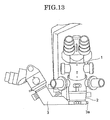
- a microscope unit 3 is rotatably attached in the circumferential direction of a lens barrel 2 of a microscope body 1 as illustrated in FIG. 13 , so as to be movable in accordance with a position that an assistant stands at the time of operation.
- the microscope unit 3 is provided with an annular section 3a which is coaxially disposed to the lens barrel 2 and is rotatably supported. For this reason, it is impossible to provide more than one microscope unit 3.
- two of the microscope units 3 can be fastened to the right and left of the lens barrel 2.
- the microscope unit 3 can be previously removed from the lens barrel 2 before the operation.
- the microscope unit it is preferable for the microscope unit not to disturb the operator even if a plurality of microscope units 3 is provided as described above.
- an object of the present invention to provide an operation microscope in which a microscope unit for an assistant is movable between a usage position and a non-usage position, regardless of the number of microscope units.
- an aspect of the present invention relates to an operation microscope including, a microscope body having an illumination optical system which illuminates a subject, a lens barrel, and a main observation optical system which observes the subject, a microscope unit for an assistant attached to the microscope body, and a guide rail which is disposed in the lens barrel of the microscope body, and extends in a circumferential direction about a center of an optical axis of an objective lens of the microscope body, wherein the microscope unit for an assistant is disposed in the guide rail to be movable between a usage position and a non-usage position in a circumferential direction of the lens barrel.
- FIG. 1 illustrates an operation microscope according to the embodiment of the present invention.
- the operation microscope includes a microscope body 11.
- the microscope body 11 includes a main microscope unit 12 for an operator and a housing 13 integrally provided in the rear side of the main microscope unit 12.
- the main microscope unit 12 includes a lens barrel 12a in which an objective lens 12c is built and right, and left eye lenses 12b, 12b for an operator.
- the main microscope unit 12 includes a main observation optical system (observation system for an operator) illustrated by M in FIGs. 6, 7 .
- the main observation optical system M includes right and left observation optical systems ML, MR (not shown in detail). The detailed explanation of the main optical system M is omitted because a known structure can be adopted for the main observation optical system M.
- the housing 13 includes inside thereof an illumination optical system (not shown).
- the illumination luminous flux from the illumination optical system can be projected onto a subject via a luminous flux deflection member 13 a such as a prism and an objective lens 12c.
- a luminous flux deflection member 13 a such as a prism and an objective lens 12c.
- the detailed explanation of the illumination optical system is also omitted because a known structure can be adopted for the illumination optical system.
- the lens barrel 12a includes inside thereof luminous flux reflection members 12d, 12d' such as prisms, which reflect toward the openings 12L, 12R and 12L', 12R', respectively, the observation luminous fluxes reflected from the subject (not shown) to enter onto the objective lens 12c.
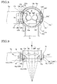
- the lower end part of the main microscope unit 12 is provided with a guide rail which extends to the lens barrel 12a and the housing 13 as illustrated in FIGs. 2, 3 .
- the guide rail 14 includes a circular arc guide section 15, which extends in the circumferential direction along the lens barrel 12a, and linear guide sections 16, 16' which extend from the circular arc guide section 15 to the right and left sides of the housing 13, respectively.
- the circular arc guide section 15 extends in the circumferential direction centering on the optical axis of the objective lens 12c.
- the one end part of the circular arc guide section 15 is provided with a pair of openings 15L, 15R (refer to FIG. 5 ) opposed to (communicating with) a pair of openings 12L, 12R.
- the other end part of the circular arc guide section 15 is provided with a pair of openings 15L', 15R' opposed to (communicating with) a pair of openings 12L', 12R'.
- microscope mounts 17, 17' are mounted on the guide rail 14 so as to be movably disposed along the lens barrel 12a.
- the microscope mount 17 includes openings 17L, 17R opposed to (communicating with) the openings 15L, 15R, respectively.
- the microscope mount 17' includes openings 17L', 17R' opposed to (communicating with) the openings 15L', 15R'.
- Each of the microscope mounts 17, 17' includes a groove 17a, 17a' to which a microscope unit for an assistant Su, Su' (not shown entirely, hereinafter referred to as a microscope unit) is attached.
- the microscope unit Su for an assistant includes a projection Sa which engages with the groove 17a, and a stopper projection Sb which has contact with the upper end of the microscope mount 17, so as to prevent the falling of the microscope unit Su when the projection Sa engages with the groove 17a.
- the microscope unit Su' for an assistant also includes a projection Sa' which engages with the groove 17a', and a stopper projection Sb' which has contact with the upper end of the microscope mount 17', so as to prevent the falling of the microscope unit Su' when the projection Sa' engages with the groove 17'.
- Each of the microscope units Su, Su' includes an optical system for an assistant Sc, Sc' illustrated in FIG. 6 . The details of the optical systems Sc, Sc' are omitted because a known structure can be adopted for the optical systems Sc, Sc'.
- the microscope unit Su for an assistant is detachably attached to the microscope mount 17 by fastening the stopper projection Sb to screw holes 17b of the microscope mount 17 by means of fastening screws (not shown).
- the microscope unit Su' for an assistant is also detachably attached to the microscope mount 17' by fastening the stopper projection Sb' to screw holes 17b' of the microscope mount 17' by means of fastening screws (not shown).
- the microscope mount 17 is fastenably provided in the end part of the circular arc guide section 15 at a position (usage position) that the openings 17L, 17R are opposed to (communicating with) the openings 15L, 15R.
- This fastening can be conducted by means of a fastening pin or a fastening screw (not shown), for example.
- This structure is the same as the microscope mount 17'.
- the microscope mount 17' can be moved to a position illustrated by a two-point dotted line from the end part (usage position) of the circular arc guide section 15 illustrated by the solid line in FIG. 2 . More particularly, the microscope mount 17' can be disposed in the linear guide section (non-usage position) 16' as illustrated by the solid line from the position illustrated by the two-point dotted line by moving the microscope mount 17' in the direction of the arrow A1 in FIG. 3 . Moreover, the microscope mount 17 can be disposed in the linear guide section (non-usage position) 16 by moving the microscope mount 17 in a direction opposite to the direction of the arrow A1 in FIG. 3 from the end part (usage position) of the circular arc guide section 15.
- the microscope mounts 17, 17' are fastenably provided in the linear guide sections 16, 16' (non-usage position), respectively.
- These fastenings can be achieved by means of a fastening pin or a fastening screw (not shown), for example.
- the outer circumferential face of the circular arc guide section 15 is provided with plate-like circular arc shutters 15s, 15s' which are movable in the circumferential direction.
- an upper supporting groove (not shown) which extends in the circumferential direction and opens downwardly is formed on the upper end part of the outer circumferential face of the circular arc guide section 15, and a lower supporting groove (not shown) which extends in the circumferential direction and opens upwardly is formed on the lower end part of the outer circumferential face of the circular arc guide section 15, so that the upper end part and the lower end part of the shutters 15s, 15s' engage with the upper supporting groove and the lower supporting groove, respectively.
- the openings 15L, 15R are closed by the shutter 15s.
- the openings 15L', 15R' are closed by the shutter 15s'.
- the shutters 15s, 15s' can be opened and closed in conjugation with the movement of the microscope mounts 17, 17' by means of a wire or a connection pin (not shown), for example.
- FIGs. 2, 3 an example in which a pair of right and left microscope mounts 17, 17' and a pair of right and left microscope units Su, Su' are disposed is illustrated; however, it is not limited thereto.
- the microscope mount 17 can be moved in the circumferential direction of the lens barrel 12a along the circular arc guide section 15 of the guide rail 14, so that the microscope mount 17 can be disposed in either the right usage position or the left usage position (the position of the openings 15L, 15R or the position of the openings 15L', 15R').
- linear guide sections 16, 16 of the guide rail 14 illustrated in FIGs. 2, 3 can be omitted as illustrated in FIGs. 10-12 , and only the circular arc guide section 15 illustrated in FIGs. 2, 3 can be used as a guide rail 14' as illustrated in FIGs. 10-12 .
- the microscope mount 17' can be removed from the end of the guide rail 14' together with a microscope unit for an assistant (not shown) when moving the microscope mount 17' from the usage position in FIG. 11 to the removing space (non-usage position) 18 provided in the side of the housing 13.
- the microscope mount 17 can be removed from the guide rail 14' of the lens barrel 12a by moving the microscope mount 17 to the removing space (non-usage position) 18.
- the openings 15L, 15R and the openings 15L7, 15R' are opened by the shutters 15s, 15s'.
- the operation microscope includes an illumination optical system which illuminates a subject, the microscope body 11 having the main observation optical system which observes the subject, and the microscope unit for an assistant (Su, Su') attached to the microscope body.
- the operation microscope includes the guide rail 14 which is disposed in the lens barrel 12a of the microscope body 11, and extends in the circumferential direction about the center of the optical axis of the objective lens 12c of the microscope body 11, and the microscope unit (Su, Su') for an assistant is disposed in the guide rail 14 to be movable between the usage position and the non-usage position in the circumferential direction of the lens barrel 12.
- the microscope unit (Su, Su') for an assistant since the microscope unit (Su, Su') for an assistant is attached to the guide rail 14 to be movable from the usage position and the non-usage position, the microscope unit (Su, Su') for an assistant can be moved to the non-usage position regardless of the number of microscope units.
- the guide rail 14 includes the guide section (guide rail 14') which moves the microscope unit (Su, Su') for an assistant from the usage position to the non-usage position.
- the microscope unit for an assistant by moving the microscope unit (Su, Su') for an assistant to the non-usage position (removing space 18), the microscope unit for an assistant (Su, Su') can be disposed without inconveniencing the operator.
- the microscope unit (Su, Su') for an assistant is removable from both ends in the non-usage positions (removing space 18) of the guide rail 14'.
- the microscope unit for an assistant (Su, Su') can be easily removed from the guide rail at the non-usage position, the microscope unit (Su, Su') for an assistant can be disposed without inconveniencing the operator.
Landscapes
- Physics & Mathematics (AREA)
- Chemical & Material Sciences (AREA)
- Analytical Chemistry (AREA)
- General Physics & Mathematics (AREA)
- Optics & Photonics (AREA)
- Health & Medical Sciences (AREA)
- General Health & Medical Sciences (AREA)
- Surgery (AREA)
- Microscoopes, Condenser (AREA)
Abstract
Description
- The present application is based on and claims priority from Japanese Patent Application No.
2007-091891, filed on March 30, 2007 - The present invention relates to an operation microscope including a microscope unit for an assistant.
- There is known a conventional operation microscope including a microscope body having a main observation optical system which observes a subject, and a microscope unit for an assistant (hereinafter referred to as a microscope unit) attached to the microscope body (refer to
JP2006-280805A - In such an operation microscope, a
microscope unit 3 is rotatably attached in the circumferential direction of alens barrel 2 of amicroscope body 1 as illustrated inFIG. 13 , so as to be movable in accordance with a position that an assistant stands at the time of operation. - However, in this operation microscope, the
microscope unit 3 is provided with anannular section 3a which is coaxially disposed to thelens barrel 2 and is rotatably supported. For this reason, it is impossible to provide more than onemicroscope unit 3. - As a measure for this problem, two of the
microscope units 3 can be fastened to the right and left of thelens barrel 2. In this fastening structure of themicroscope units 3, if themicroscope unit 3 is inconvenient to an operator, themicroscope unit 3 can be previously removed from thelens barrel 2 before the operation. - However, it is preferable for the microscope unit not to disturb the operator even if a plurality of
microscope units 3 is provided as described above. - It is, therefore, an object of the present invention to provide an operation microscope in which a microscope unit for an assistant is movable between a usage position and a non-usage position, regardless of the number of microscope units.
- In order to achieve the above object, an aspect of the present invention relates to an operation microscope including, a microscope body having an illumination optical system which illuminates a subject, a lens barrel, and a main observation optical system which observes the subject, a microscope unit for an assistant attached to the microscope body, and a guide rail which is disposed in the lens barrel of the microscope body, and extends in a circumferential direction about a center of an optical axis of an objective lens of the microscope body, wherein the microscope unit for an assistant is disposed in the guide rail to be movable between a usage position and a non-usage position in a circumferential direction of the lens barrel.
- These and other features, aspects, and advantages of the present invention will become better understood with regard to the following description, appended claims, and accompanying drawings.
-
FIG. 1 is a perspective view illustrating an operation microscope according to one embodiment of the present invention. -
FIG. 2 is a schematic diagram illustrating a guide rail of the operation microscope inFIG. 1 . -
FIG. 3 is a schematic diagram for use illustrating the guide rail of the operation microscope inFIG. 2 . -
FIG. 4 is a partially enlarged explanatory view illustrating a lens barrel of the operation microscope inFIG. 1 . -
FIG. 5 is a partially enlarged explanatory view illustrating the guide rail of the operation microscope inFIG. 1 . -
FIG. 6 is a horizontal sectional view illustrating a lower part of the lens barrel inFIG. 1 . -
FIG. 7 is a longitudinal sectional view illustrating the lens barrel inFIG. 6 . -
FIG. 8 is a horizontal sectional view of a lens barrel illustrating another modification example of the operation microscope according to the present invention. -
FIG. 9 is a longitudinal sectional view illustrating the lens barrel inFIG. 8 . -
FIG. 10 is a perspective view illustrating another modification example of the operation microscope according to the present invention. -
FIG. 11 is a schematic diagram illustrating a guide rail of the operation microscope inFIG. 10 . -
FIG. 12 is a schematic diagram for use illustrating the operation microscope inFIG. 10 . -
FIG. 13 is a perspective view illustrating one example of a conventional operation microscope. - Hereinafter, an embodiment of the present invention will be described with reference to the drawings.
-
FIG. 1 illustrates an operation microscope according to the embodiment of the present invention. The operation microscope includes amicroscope body 11. Themicroscope body 11 includes amain microscope unit 12 for an operator and ahousing 13 integrally provided in the rear side of themain microscope unit 12. - The
main microscope unit 12 includes alens barrel 12a in which anobjective lens 12c is built and right, andleft eye lenses main microscope unit 12 includes a main observation optical system (observation system for an operator) illustrated by M inFIGs. 6, 7 . The main observation optical system M includes right and left observation optical systems ML, MR (not shown in detail). The detailed explanation of the main optical system M is omitted because a known structure can be adopted for the main observation optical system M. - The
housing 13 includes inside thereof an illumination optical system (not shown). The illumination luminous flux from the illumination optical system can be projected onto a subject via a luminousflux deflection member 13 a such as a prism and anobjective lens 12c. The detailed explanation of the illumination optical system is also omitted because a known structure can be adopted for the illumination optical system. - Provided in the left side part of the lower end part of the
main microscope unit 12 is a pair ofopenings FIG. 4 ) as illustrated inFIG. 6 , and also provided in the right side part of the lower end part of themain microscope unit 12 is a pair ofopenings 12L', 12R'. Thelens barrel 12a includes inside thereof luminousflux reflection members openings objective lens 12c. - The lower end part of the
main microscope unit 12 is provided with a guide rail which extends to thelens barrel 12a and thehousing 13 as illustrated inFIGs. 2, 3 . Theguide rail 14 includes a circulararc guide section 15, which extends in the circumferential direction along thelens barrel 12a, andlinear guide sections 16, 16' which extend from the circulararc guide section 15 to the right and left sides of thehousing 13, respectively. The circulararc guide section 15 extends in the circumferential direction centering on the optical axis of theobjective lens 12c. - As illustrated in
FIG. 6 , the one end part of the circulararc guide section 15 is provided with a pair ofopenings FIG. 5 ) opposed to (communicating with) a pair ofopenings arc guide section 15 is provided with a pair ofopenings 15L', 15R' opposed to (communicating with) a pair ofopenings 12L', 12R'. - In addition,
microscope mounts 17, 17' are mounted on theguide rail 14 so as to be movably disposed along thelens barrel 12a. Themicroscope mount 17 includesopenings openings openings 17L', 17R' opposed to (communicating with) theopenings 15L', 15R'. - Each of the
microscope mounts 17, 17' includes agroove - The microscope unit Su for an assistant includes a projection Sa which engages with the
groove 17a, and a stopper projection Sb which has contact with the upper end of themicroscope mount 17, so as to prevent the falling of the microscope unit Su when the projection Sa engages with thegroove 17a. The microscope unit Su' for an assistant also includes a projection Sa' which engages with thegroove 17a', and a stopper projection Sb' which has contact with the upper end of the microscope mount 17', so as to prevent the falling of the microscope unit Su' when the projection Sa' engages with the groove 17'. Each of the microscope units Su, Su' includes an optical system for an assistant Sc, Sc' illustrated inFIG. 6 . The details of the optical systems Sc, Sc' are omitted because a known structure can be adopted for the optical systems Sc, Sc'. - The microscope unit Su for an assistant is detachably attached to the
microscope mount 17 by fastening the stopper projection Sb to screwholes 17b of themicroscope mount 17 by means of fastening screws (not shown). The microscope unit Su' for an assistant is also detachably attached to the microscope mount 17' by fastening the stopper projection Sb' to screwholes 17b' of the microscope mount 17' by means of fastening screws (not shown). - The
microscope mount 17 is fastenably provided in the end part of the circulararc guide section 15 at a position (usage position) that theopenings openings - The microscope mount 17' can be moved to a position illustrated by a two-point dotted line from the end part (usage position) of the circular
arc guide section 15 illustrated by the solid line inFIG. 2 . More particularly, the microscope mount 17' can be disposed in the linear guide section (non-usage position) 16' as illustrated by the solid line from the position illustrated by the two-point dotted line by moving the microscope mount 17' in the direction of the arrow A1 inFIG. 3 . Moreover, themicroscope mount 17 can be disposed in the linear guide section (non-usage position) 16 by moving themicroscope mount 17 in a direction opposite to the direction of the arrow A1 inFIG. 3 from the end part (usage position) of the circulararc guide section 15. - In these positions, the microscope mounts 17, 17' are fastenably provided in the
linear guide sections 16, 16' (non-usage position), respectively. These fastenings can be achieved by means of a fastening pin or a fastening screw (not shown), for example. - As illustrated in
FIG. 6 , the outer circumferential face of the circulararc guide section 15 is provided with plate-like circular arc shutters 15s, 15s' which are movable in the circumferential direction. As the structure for attaching these shutters, for example, an upper supporting groove (not shown) which extends in the circumferential direction and opens downwardly is formed on the upper end part of the outer circumferential face of the circulararc guide section 15, and a lower supporting groove (not shown) which extends in the circumferential direction and opens upwardly is formed on the lower end part of the outer circumferential face of the circulararc guide section 15, so that the upper end part and the lower end part of the shutters 15s, 15s' engage with the upper supporting groove and the lower supporting groove, respectively. - In addition, when the
microscope mount 17 is fastened to the linear guide section 16 (non-usage position), theopenings openings 15L', 15R' are closed by the shutter 15s'. - The shutters 15s, 15s' can be opened and closed in conjugation with the movement of the microscope mounts 17, 17' by means of a wire or a connection pin (not shown), for example.
- Moreover, in
FIGs. 2, 3 , an example in which a pair of right and left microscope mounts 17, 17' and a pair of right and left microscope units Su, Su' are disposed is illustrated; however, it is not limited thereto. For example, as illustrated inFIGs. 8, 9 , only onemicroscope mount 17 can be disposed, and themicroscope mount 17 can be moved in the circumferential direction of thelens barrel 12a along the circulararc guide section 15 of theguide rail 14, so that themicroscope mount 17 can be disposed in either the right usage position or the left usage position (the position of theopenings openings 15L', 15R'). - Furthermore, in the above-described embodiment, an example in which the circular
arc guide section 15 and thelinear guide sections guide rail 14 is illustrated; however, it is not limited thereto. - For example, the
linear guide sections guide rail 14 illustrated inFIGs. 2, 3 can be omitted as illustrated inFIGs. 10-12 , and only the circulararc guide section 15 illustrated inFIGs. 2, 3 can be used as a guide rail 14' as illustrated inFIGs. 10-12 . - In this case, by providing an removing space (non-usage position) 18 in one side of the right and left of the
housing 13 illustrated inFIG. 10 , the microscope mount 17' can be removed from the end of the guide rail 14' together with a microscope unit for an assistant (not shown) when moving the microscope mount 17' from the usage position inFIG. 11 to the removing space (non-usage position) 18 provided in the side of thehousing 13. - In
FIG. 12 , after moving the remainingmicroscope mount 17 in the direction of the arrow A1, themicroscope mount 17 can be removed from the guide rail 14' of thelens barrel 12a by moving themicroscope mount 17 to the removing space (non-usage position) 18. - As described above, if the microscope mounts 17, 17' are removed from the guide rail 14', similar to the above-described embodiments, the
openings - As described above the operation microscope according to one embodiment of the present invention includes an illumination optical system which illuminates a subject, the
microscope body 11 having the main observation optical system which observes the subject, and the microscope unit for an assistant (Su, Su') attached to the microscope body. The operation microscope includes theguide rail 14 which is disposed in thelens barrel 12a of themicroscope body 11, and extends in the circumferential direction about the center of the optical axis of theobjective lens 12c of themicroscope body 11, and the microscope unit (Su, Su') for an assistant is disposed in theguide rail 14 to be movable between the usage position and the non-usage position in the circumferential direction of thelens barrel 12. - According to this structure, since the microscope unit (Su, Su') for an assistant is attached to the
guide rail 14 to be movable from the usage position and the non-usage position, the microscope unit (Su, Su') for an assistant can be moved to the non-usage position regardless of the number of microscope units. - Moreover, in the operation microscope according to one embodiment of the present invention, the
guide rail 14 includes the guide section (guide rail 14') which moves the microscope unit (Su, Su') for an assistant from the usage position to the non-usage position. - According to this structure, by moving the microscope unit (Su, Su') for an assistant to the non-usage position (removing space 18), the microscope unit for an assistant (Su, Su') can be disposed without inconveniencing the operator.
- Furthermore, in the operation microscope according to one embodiment of the present invention, the microscope unit (Su, Su') for an assistant is removable from both ends in the non-usage positions (removing space 18) of the guide rail 14'.
- According to this structure, since the microscope unit for an assistant (Su, Su') can be easily removed from the guide rail at the non-usage position, the microscope unit (Su, Su') for an assistant can be disposed without inconveniencing the operator.
Although the present invention has been described in terms of exemplary embodiments, it is not limited thereto. It should be appreciated that variations may be made in the embodiments described by persons skilled in the art without departing from the scope of the present invention as defined by the following claims.
Claims (6)
- An operation microscope, comprising:an illumination optical system which illuminates a subj ect;a microscope body (11) having a lens barrel (12a) and a main observation optical system (12) which observes the subject;a microscope unit (Su, Su') for an assistant attached to the microscope body (11); anda guide rail (14) which is disposed in the lens barrel (12a) of the microscope body (11), and extends in a circumferential direction about a center of an optical axis of an objective lens (12c) of the microscope body (11), whereinthe microscope unit (Su, Su') for an assistant is disposed in the guide rail (14) to be movable between a usage position and a non-usage position in a circumferential direction of the lens barrel (12a).
- The operation microscope according to Claim 1, wherein the microscope unit (Su, Su') for an assistant is removable from both ends in the non-usage position of the guide rail (14).
- The operation microscope according to Claim 1, wherein the guide rail (14) includes a circular arc guide section (15) which extends along the circumferential direction of the lens barrel (12a), and linear guide sections (16, 16') which are disposed to extend from the circular arc guide section to right and left side portions of the microscope body (11), respectively.
- The operation microscope according to Claim 1, wherein the microscope body (11) includes a pair of openings (12L, 12R, 12L', 12R') disposed in a lower end part thereof, the guide rail (14) includes a pair of openings (15L, 15R, 15L', 15R') which are opposed to the pair of openings (12L, 12R, 12L', 12R'), and the guide rail (14) includes a shutter (15s, 15s') which closes the pair of openings (12L, 12R, 12L', 12R') provided in the lower end part of the microscope body (11) and the pair of openings (15L, 15R, 15L', 15R') provided in the guide rail (14) when fastening the microscope unit (Su, Su') for an assistant to the non-usage position.
- The operation microscope according to Claim 1, wherein the microscope body (11) includes a stopper (Sb, Sb') which prevents the microscope unit (Su, Su') for an assistant from falling.
- The operation microscope according to Claim 1, wherein the usage position is located in an outer circumference face of the circular arc guide section (15), and the non-usage position is located in the linear-guide section (16, 16').
Applications Claiming Priority (1)
| Application Number | Priority Date | Filing Date | Title |
|---|---|---|---|
| JP2007091891A JP2008245980A (en) | 2007-03-30 | 2007-03-30 | Surgical microscope |
Publications (3)
| Publication Number | Publication Date |
|---|---|
| EP1975670A2 true EP1975670A2 (en) | 2008-10-01 |
| EP1975670A3 EP1975670A3 (en) | 2009-06-03 |
| EP1975670B1 EP1975670B1 (en) | 2011-11-30 |
Family
ID=39590214
Family Applications (1)
| Application Number | Title | Priority Date | Filing Date |
|---|---|---|---|
| EP08006082A Active EP1975670B1 (en) | 2007-03-30 | 2008-03-28 | Operation microscope |
Country Status (4)
| Country | Link |
|---|---|
| US (1) | US7982949B2 (en) |
| EP (1) | EP1975670B1 (en) |
| JP (1) | JP2008245980A (en) |
| CN (1) | CN101273918B (en) |
Families Citing this family (5)
| Publication number | Priority date | Publication date | Assignee | Title |
|---|---|---|---|---|
| DE102009037022B4 (en) * | 2009-08-07 | 2014-03-20 | Carl Zeiss Meditec Ag | Surgical microscope and method for pivoting a co-observer microscope |
| USD663336S1 (en) * | 2010-07-27 | 2012-07-10 | Carl Zeiss Meditec Ag | Tube for surgical microscope |
| CN102928971B (en) * | 2012-11-12 | 2015-09-09 | 杨勋 | Microscope |
| JP2018027139A (en) * | 2016-08-15 | 2018-02-22 | 三鷹光器株式会社 | Surgical microscope system |
| KR101931540B1 (en) * | 2017-07-31 | 2018-12-24 | 주식회사 고영테크놀러지 | Stereo microscope, optical apparatus, and method for forming optical path using same |
Citations (2)
| Publication number | Priority date | Publication date | Assignee | Title |
|---|---|---|---|---|
| JP2006280805A (en) | 2005-04-04 | 2006-10-19 | Topcon Corp | Surgical microscope equipment |
| JP2007091891A (en) | 2005-09-29 | 2007-04-12 | Ube Machinery Corporation Ltd | Boiler fuel production system |
Family Cites Families (6)
| Publication number | Priority date | Publication date | Assignee | Title |
|---|---|---|---|---|
| JPH0720652Y2 (en) * | 1986-03-31 | 1995-05-15 | 株式会社トプコン | Surgical microscope |
| US5052789A (en) * | 1988-09-30 | 1991-10-01 | Storz Instrument Company | Multi-user microscope with orientation adjustment and method |
| US6421173B1 (en) * | 1999-09-28 | 2002-07-16 | Leica Microsystems Ag | Stereomicroscope |
| JP2001208979A (en) * | 2000-01-27 | 2001-08-03 | Mitaka Koki Co Ltd | Stereo microscope |
| JP3944050B2 (en) * | 2001-11-05 | 2007-07-11 | オリンパス株式会社 | Surgical microscope |
| US7002738B2 (en) * | 2003-06-13 | 2006-02-21 | Leica Microsystems (Schweiz) Ag | Stereomicroscope with a co-observer tube |
-
2007
- 2007-03-30 JP JP2007091891A patent/JP2008245980A/en active Pending
-
2008
- 2008-03-27 CN CN2008100880627A patent/CN101273918B/en not_active Expired - Fee Related
- 2008-03-28 EP EP08006082A patent/EP1975670B1/en active Active
- 2008-03-28 US US12/057,555 patent/US7982949B2/en active Active
Patent Citations (2)
| Publication number | Priority date | Publication date | Assignee | Title |
|---|---|---|---|---|
| JP2006280805A (en) | 2005-04-04 | 2006-10-19 | Topcon Corp | Surgical microscope equipment |
| JP2007091891A (en) | 2005-09-29 | 2007-04-12 | Ube Machinery Corporation Ltd | Boiler fuel production system |
Also Published As
| Publication number | Publication date |
|---|---|
| EP1975670A3 (en) | 2009-06-03 |
| US20080239473A1 (en) | 2008-10-02 |
| EP1975670B1 (en) | 2011-11-30 |
| CN101273918B (en) | 2010-06-09 |
| CN101273918A (en) | 2008-10-01 |
| JP2008245980A (en) | 2008-10-16 |
| US7982949B2 (en) | 2011-07-19 |
Similar Documents
| Publication | Publication Date | Title |
|---|---|---|
| EP1975670B1 (en) | Operation microscope | |
| US4167302A (en) | Surgical microscopes with L-shaped mounting brackets | |
| US10288859B2 (en) | Surgical microscope system | |
| US8056992B2 (en) | Coupling for a movable part of a piece of furniture | |
| EP1956408B1 (en) | Microscope Iens barrel | |
| JPH11510918A (en) | Device for switching the operation method of the microscope barrel | |
| US6288838B1 (en) | Video-type stereoscopic microscope including movable field stop frame and holder | |
| EP0310514B2 (en) | Binocular microscope | |
| JP4847649B2 (en) | Microscope focusing device | |
| JP3910659B2 (en) | Optical axis adjustment mechanism for binoculars and binoculars | |
| US20010055150A1 (en) | Video-type stereoscopic microscope | |
| US7265899B2 (en) | Stereoscopic microscope | |
| JP5471100B2 (en) | Lens barrel and imaging device | |
| JP4532852B2 (en) | Polarization microscope and polarization observation intermediate tube | |
| JP3865889B2 (en) | microscope | |
| US10606024B2 (en) | Lens moving mechanism | |
| JP2003202504A5 (en) | ||
| JP3022761B2 (en) | microscope | |
| JPS58118729A (en) | Ophthalmic photographing apparatus | |
| JPH07501635A (en) | Swing-type flexible condenser for microscopes | |
| JPH0734404Y2 (en) | Optical mechanical connection structure | |
| US20250035902A1 (en) | Optical ancillary device attached to microscope and microscope assembly including the same | |
| US20190258023A1 (en) | Lens moving mechanism | |
| KR20060122390A (en) | Reflective telescope with main reflector transport | |
| JP2018060054A (en) | Surgical microscope |
Legal Events
| Date | Code | Title | Description |
|---|---|---|---|
| PUAI | Public reference made under article 153(3) epc to a published international application that has entered the european phase |
Free format text: ORIGINAL CODE: 0009012 |
|
| 17P | Request for examination filed |
Effective date: 20080328 |
|
| AK | Designated contracting states |
Kind code of ref document: A2 Designated state(s): AT BE BG CH CY CZ DE DK EE ES FI FR GB GR HR HU IE IS IT LI LT LU LV MC MT NL NO PL PT RO SE SI SK TR |
|
| AX | Request for extension of the european patent |
Extension state: AL BA MK RS |
|
| PUAL | Search report despatched |
Free format text: ORIGINAL CODE: 0009013 |
|
| AK | Designated contracting states |
Kind code of ref document: A3 Designated state(s): AT BE BG CH CY CZ DE DK EE ES FI FR GB GR HR HU IE IS IT LI LT LU LV MC MT NL NO PL PT RO SE SI SK TR |
|
| AX | Request for extension of the european patent |
Extension state: AL BA MK RS |
|
| 17Q | First examination report despatched |
Effective date: 20090903 |
|
| AKX | Designation fees paid |
Designated state(s): CH DE LI |
|
| GRAP | Despatch of communication of intention to grant a patent |
Free format text: ORIGINAL CODE: EPIDOSNIGR1 |
|
| RIN1 | Information on inventor provided before grant (corrected) |
Inventor name: TAKAGI, KAZUTOSHI |
|
| GRAS | Grant fee paid |
Free format text: ORIGINAL CODE: EPIDOSNIGR3 |
|
| GRAA | (expected) grant |
Free format text: ORIGINAL CODE: 0009210 |
|
| AK | Designated contracting states |
Kind code of ref document: B1 Designated state(s): CH DE LI |
|
| REG | Reference to a national code |
Ref country code: CH Ref legal event code: EP |
|
| REG | Reference to a national code |
Ref country code: DE Ref legal event code: R096 Ref document number: 602008011632 Country of ref document: DE Effective date: 20120126 |
|
| PLBE | No opposition filed within time limit |
Free format text: ORIGINAL CODE: 0009261 |
|
| STAA | Information on the status of an ep patent application or granted ep patent |
Free format text: STATUS: NO OPPOSITION FILED WITHIN TIME LIMIT |
|
| REG | Reference to a national code |
Ref country code: CH Ref legal event code: PL |
|
| 26N | No opposition filed |
Effective date: 20120831 |
|
| REG | Reference to a national code |
Ref country code: DE Ref legal event code: R097 Ref document number: 602008011632 Country of ref document: DE Effective date: 20120831 |
|
| PG25 | Lapsed in a contracting state [announced via postgrant information from national office to epo] |
Ref country code: CH Free format text: LAPSE BECAUSE OF NON-PAYMENT OF DUE FEES Effective date: 20120331 Ref country code: LI Free format text: LAPSE BECAUSE OF NON-PAYMENT OF DUE FEES Effective date: 20120331 |
|
| PGFP | Annual fee paid to national office [announced via postgrant information from national office to epo] |
Ref country code: DE Payment date: 20260204 Year of fee payment: 19 |