EP1975579A1 - Optical spectrum analyzer - Google Patents
Optical spectrum analyzer Download PDFInfo
- Publication number
- EP1975579A1 EP1975579A1 EP07713610A EP07713610A EP1975579A1 EP 1975579 A1 EP1975579 A1 EP 1975579A1 EP 07713610 A EP07713610 A EP 07713610A EP 07713610 A EP07713610 A EP 07713610A EP 1975579 A1 EP1975579 A1 EP 1975579A1
- Authority
- EP
- European Patent Office
- Prior art keywords
- light
- wavelength
- spectrum analyzer
- optical spectrum
- optical
- Prior art date
- Legal status (The legal status is an assumption and is not a legal conclusion. Google has not performed a legal analysis and makes no representation as to the accuracy of the status listed.)
- Withdrawn
Links
- 230000003287 optical effect Effects 0.000 title claims abstract description 121
- 238000001228 spectrum Methods 0.000 title claims abstract description 80
- 239000000758 substrate Substances 0.000 claims abstract description 13
- 230000001419 dependent effect Effects 0.000 claims abstract description 10
- 108091008695 photoreceptors Proteins 0.000 claims description 9
- 239000000835 fiber Substances 0.000 claims description 7
- 230000000644 propagated effect Effects 0.000 claims description 6
- 230000008859 change Effects 0.000 abstract description 23
- 239000013307 optical fiber Substances 0.000 description 16
- 230000010287 polarization Effects 0.000 description 12
- 238000010586 diagram Methods 0.000 description 11
- 239000010410 layer Substances 0.000 description 8
- 238000012937 correction Methods 0.000 description 7
- 230000004048 modification Effects 0.000 description 7
- 238000012986 modification Methods 0.000 description 7
- 238000005259 measurement Methods 0.000 description 6
- 239000012792 core layer Substances 0.000 description 5
- 238000010897 surface acoustic wave method Methods 0.000 description 4
- 238000005549 size reduction Methods 0.000 description 3
- 238000010408 sweeping Methods 0.000 description 3
- 229910003327 LiNbO3 Inorganic materials 0.000 description 1
- 239000000956 alloy Substances 0.000 description 1
- 229910045601 alloy Inorganic materials 0.000 description 1
- 239000000919 ceramic Substances 0.000 description 1
- 238000006243 chemical reaction Methods 0.000 description 1
- 229910052802 copper Inorganic materials 0.000 description 1
- 239000013078 crystal Substances 0.000 description 1
- 230000007547 defect Effects 0.000 description 1
- 238000006073 displacement reaction Methods 0.000 description 1
- 230000005284 excitation Effects 0.000 description 1
- 239000002184 metal Substances 0.000 description 1
- 229910052751 metal Inorganic materials 0.000 description 1
- 238000000034 method Methods 0.000 description 1
- 238000012806 monitoring device Methods 0.000 description 1
- 238000012544 monitoring process Methods 0.000 description 1
- 230000009467 reduction Effects 0.000 description 1
- 230000028016 temperature homeostasis Effects 0.000 description 1
Images




Classifications
-
- G—PHYSICS
- G01—MEASURING; TESTING
- G01J—MEASUREMENT OF INTENSITY, VELOCITY, SPECTRAL CONTENT, POLARISATION, PHASE OR PULSE CHARACTERISTICS OF INFRARED, VISIBLE OR ULTRAVIOLET LIGHT; COLORIMETRY; RADIATION PYROMETRY
- G01J3/00—Spectrometry; Spectrophotometry; Monochromators; Measuring colours
- G01J3/12—Generating the spectrum; Monochromators
- G01J3/1256—Generating the spectrum; Monochromators using acousto-optic tunable filter
-
- G—PHYSICS
- G01—MEASURING; TESTING
- G01J—MEASUREMENT OF INTENSITY, VELOCITY, SPECTRAL CONTENT, POLARISATION, PHASE OR PULSE CHARACTERISTICS OF INFRARED, VISIBLE OR ULTRAVIOLET LIGHT; COLORIMETRY; RADIATION PYROMETRY
- G01J3/00—Spectrometry; Spectrophotometry; Monochromators; Measuring colours
- G01J3/02—Details
-
- G—PHYSICS
- G01—MEASURING; TESTING
- G01J—MEASUREMENT OF INTENSITY, VELOCITY, SPECTRAL CONTENT, POLARISATION, PHASE OR PULSE CHARACTERISTICS OF INFRARED, VISIBLE OR ULTRAVIOLET LIGHT; COLORIMETRY; RADIATION PYROMETRY
- G01J3/00—Spectrometry; Spectrophotometry; Monochromators; Measuring colours
- G01J3/02—Details
- G01J3/0256—Compact construction
-
- G—PHYSICS
- G01—MEASURING; TESTING
- G01J—MEASUREMENT OF INTENSITY, VELOCITY, SPECTRAL CONTENT, POLARISATION, PHASE OR PULSE CHARACTERISTICS OF INFRARED, VISIBLE OR ULTRAVIOLET LIGHT; COLORIMETRY; RADIATION PYROMETRY
- G01J9/00—Measuring optical phase difference; Determining degree of coherence; Measuring optical wavelength
- G01J9/02—Measuring optical phase difference; Determining degree of coherence; Measuring optical wavelength by interferometric methods
- G01J9/0246—Measuring optical wavelength
-
- G—PHYSICS
- G01—MEASURING; TESTING
- G01J—MEASUREMENT OF INTENSITY, VELOCITY, SPECTRAL CONTENT, POLARISATION, PHASE OR PULSE CHARACTERISTICS OF INFRARED, VISIBLE OR ULTRAVIOLET LIGHT; COLORIMETRY; RADIATION PYROMETRY
- G01J9/00—Measuring optical phase difference; Determining degree of coherence; Measuring optical wavelength
- G01J9/04—Measuring optical phase difference; Determining degree of coherence; Measuring optical wavelength by beating two waves of a same source but of different frequency and measuring the phase shift of the lower frequency obtained
Definitions
- the present invention relates to an optical spectrum analyzer using a waveguide acousto-optic tunable filter.
- Patent Document 1 discloses an optical spectrum analyzer including a tunable filter using an arrayed waveguide grating.
- the arrayed waveguide grating by using the arrayed waveguide grating, light having a target wavelength is extracted.
- Patent Document 1 also includes the description that, by thermoregulating the arrayed waveguide grating, a wavelength can be changed.
- Patent Document 2 discloses an optical spectrum analyzer using a tunable fiber grating.
- the optical spectrum analyzer is configured so that, by extending or contracting the fiber grating by using a piezoelectric element, a wavelength can be changed.
- the spectrum analyzer does not include any mechanical driving parts, but takes a relatively long time by the time its temperature changes. Thus, this optical spectrum analyzer is unsuitable for high speed measurement.
- the optical spectrum analyzer using the wavelength variable fiber grating, as described in Patent Document 2, is small since it uses a piezoelectric element, and can perform measurement at high speed. However, it has a problem of a narrow tunable range.
- AOTF waveguide acousto-optic tunable filter
- the present invention provides an optical spectrum analyzer for detecting a light output that is dependent on the frequency of light in a wavelength range of light to be measured, the optical spectrum analyzer comprising: a waveguide acousto-optic tunable filter including a piezoelectric substrate, an optical waveguide provided on the piezoelectric substrate, and an IDT for converting the mode of light being propagated in the middle of the optical waveguide; a light source for giving, to the waveguide acousto-optic tunable filter, reference light having a particular wavelength outside the wavelength range; a driving circuit for exciting the IDT of the waveguide acousto-optic tunable filter by supplying a high frequency signal; a photoreceptor that receives light that is output from the waveguide acousto-optic tunable filter; and an arithmetic device in which, on the basis of:
- the light source includes a light generator that generates light having various wavelengths, and a fiber Bragg grating (FBG) that enables, from the light given from the light generator, output of only light having a particular wavelength.
- FBG fiber Bragg grating
- the light source is a laser source.
- the laser source In the case of using the laser source, light having a particular wavelength can be obtained from the laser source.
- the FBG or the like is not needed, and size reduction and structure simplification of the light source can be achieved.
- the light source is configured so that first and second types of light having different wavelengths are given as the reference light, and a relationship between the frequency of the high frequency waves applied to the IDT and the wavelength of the selected light is corrected using the first and second types of light. Therefore, as described later, a relationship between the wavelength of selected light and the frequency of the high frequency signal for exciting the IDT can be ascertained at two points.
- the optical spectrum can be measured with higher accuracy.
- an optical spectrum analyzer for use in combination with an optical sensor for detecting a predetermined physical quantity, wherein the optical sensor includes a light source and an optical detecting unit, and the light source of the optical spectrum analyzer is shared with the light source of the optical sensor.
- the entirety of an apparatus including the optical sensor and the optical spectrum analyzer can be reduced in size.
- the optical spectrum analyzer in the case of detecting a light output that is dependent on the frequency of light in a wavelength range of light to be measured, since the optical spectrum analyzer includes the waveguide acousto-optic tunable filter, the light source, the driving circuit, the photoreceptor, and the arithmetic device, by using the reference light, whose wavelength is known beforehand, the frequency of a signal for exciting the IDT can be accurately converted into the wavelength of the selected light.
- the light to be measured is propagated in a single polarization mode along the optical waveguide.
- the polarization mode of the light being propagated is converted, and, from the acousto-optic tunable filter, light having a particular wavelength can be separated and output.
- the wavelength of the selected light that is output corresponds to the frequency of the high frequency signal applied to the IDT at 1:1. Therefore, by changing the frequency of the signal for exciting the IDT in accordance with the wavelength range, the light output that is dependent on the frequency of light in a wavelength range can be detected.
- the frequency of the high frequency signal for exciting the IDT corresponds to the wavelength of the selected light at 1:1
- a ratio at which the wavelength of the selected light changes when the frequency of the high frequency signal is changed changes depending on the temperature.
- df is a change in frequency of the high frequency signal
- d ⁇ is a change in wavelength of the selected light to the frequency of the high frequency signal
- d ⁇ /df has temperature dependency. Therefore, there is a possibility that the wavelength of the selected light may shift from a wavelength corresponding to the frequency of the high frequency signal applied when the IDT is excited, depending on the operating temperature.
- reference light having a known particular wavelength is input from the light source.
- a high frequency signal having a predetermined frequency is applied, on the basis of the frequency of the high frequency signal and the wavelength of selected light, the wavelength of the selected light, which is selected from the light to be measured, is corrected. Therefore, the optical spectrum can be detected with higher accuracy, despite a change in temperature.
- the optical spectrum can be measured with high speed and higher accuracy.
- Fig. 1 is a schematic diagram of the configuration of an optical spectrum analyzer according to a first embodiment of the present invention.
- the optical spectrum analyzer 1 of the present invention includes a waveguide acousto-optic tunable filter 2 to which light to be measured is input and from which selected light is output.
- the waveguide acousto-optic tunable filter 2 is configured by using a piezoelectric substrate 3.
- the piezoelectric substrate 3 is formed of a LiNbO 3 piezoelectric monocrystal substrate.
- the piezoelectric substrate 3 may be formed of a different piezoelectric monocrystal or may be formed of piezoelectric ceramic.
- optical waveguides 4a and 4b are provided on the piezoelectric substrate 3.
- An IDT 5 is provided in a part of the optical waveguides 4a and 4b.
- the IDT 5 is electrically connected to a driving circuit 6.
- the IDT 5 consists of a pair of interdigitated comb electrodes having a plurality of electrode fingers.
- a high frequency signal is applied to the IDT 5
- the IDT 5 is excited and a surface acoustic wave is excited. This excitation of the surface acoustic wave converts a polarization mode of light that propagates in the optical waveguides 4a and 4b in a single polarization mode.
- a cross waveguide polarizing splitter 7 is provided closer to an input side than the IDT 5, and a cross waveguide polarizing splitter 8 is similarly provided on an output side of the optical waveguides 4a and 4b.
- the waveguide acousto-optic tunable filter 2 that includes the optical waveguides 4a and 4b, the IDT 5, and the polarizing splitters 7 and 8 has been known as a non-dependent AOTF.
- waveguide acousto-optic tunable filter 2 which is a non-polarization-dependent AOTF
- light to be measured and reference light, which is described below, are incident on one incident end 7a of the polarizing splitter 7 provided on an incident side.
- selected light is emitted from one emitting end 8a of the second cross waveguide polarizing splitter 8.
- the IDT 5 can be formed of Al, Cu, or a proper metal or alloy.
- optical waveguides 4a and 4b, and the cross waveguide polarizing splitters 7 and 8 can be formed in accordance with a known technique in which Ti is diffused in part of a piezoelectric substrate.
- an incident optical fiber 9 is connected to the one incident end 7a of the waveguide acousto-optic tunable filter 2.
- the light to be measured or the reference light is incident on the incident optical fiber 9.
- the reference light is incident from a light source 10 on the incident optical fiber 9.
- the light source 10 includes a wideband light source 11 having a relatively wide band (that is, the wideband light source 11, which generates light having various wavelengths), an optical circulator 12, and an FBG 13.
- the FBG 13 is a fiber Bragg grating, and has a function of reflecting and emitting light having a predetermined wavelength.
- the wavelength of the reference light is outside a wavelength range in which the spectrum of the light to be measured is measured and is within a wavelength range that can be monitored by the AOTF.
- Fig. 2 is a schematic perspective view illustrating functions of the FBG 13.
- the FBG 13 is provided as part of the optical fiber or is provided so as to be joined to the optical fiber.
- the FBG 13 has a core layer 13a, and a clad layer 13b provided around the core layer 13a.
- the FBG 13 has a refractive index difference between the core layer 13a and the clad layer 13b.
- a different refractive index layer 13c having a refractive index different from that of the core layer 13a is provided at a predetermined pitch.
- the different refractive index layer 13c is provided at the predetermined pitch, as indicated by the arrow A, in the light that is incident, only light having a wavelength matching the pitch of the different refractive index layer 13c is reflected as indicated by the arrow B. In other words, only light having a particular wavelength is reflected as indicated by the arrow B, and light having other wavelengths is transmitted.
- a wideband light source such as an ASE light source, can be used as the light source 11.
- an optical fiber 14 is connected to the emitting end 8a of the waveguide acousto-optic tunable filter 2.
- a photoreceptor 15 is connected to an output side of the optical fiber 14.
- the photoreceptor 15 is formed of, for example, a proper photoelectric conversion element such as a photodiode, and outputs an electric signal in accordance with the intensity of input light.
- an arithmetic device 16 is electrically connected to the photoreceptor 15. Also, the arithmetic device 16 is electrically connected to the driving circuit 6.
- the arithmetic device 16 calculates a light output that is output in accordance with an electric signal given from the photoreceptor 15. Also, as described below, on the basis of a relationship between the frequency of a high frequency signal that is applied in order to excite the IDT 5 and a known wavelength of the reference light, the arithmetic device 16 corrects a relationship between the frequency of the high frequency signal and the wavelength of selected light selected from the light to be measured, and gives a highly accurate optical spectrum.
- the optical spectrum analyzer 1 An operation of the optical spectrum analyzer 1 according to this embodiment will be described.
- the light to be measured is incident from the input optical fiber 9 on the one incident end 7a.
- the light to be measured includes light having various wavelength components. Accordingly, with the optical spectrum analyzer 1, an output change dependent on the wavelength of light in a wavelength range, that is, a light output dependent on the frequency of light in a wavelength range, is measured.
- incident light is split by the polarizing splitter 7 into TE mode light and TM mode light.
- the TE mode light or TM mode light is guided to one optical waveguide 4a, and the TM mode light or TE mode light is guided to the other optical waveguide 4b.
- the IDT 5 is excited and a surface acoustic wave is propagated.
- This propagation of the surface acoustic wave deforms a crystal structure of the piezoelectric substrate 3, so that, among polarization modes in which propagation through the optical waveguides 4a and 4b is performed in a single polarization mode, a polarization mode of polarization of a particular wavelength according to the frequency of an IDT driving high frequency signal is converted.
- a high frequency signal having a frequency fa is applied from the driving circuit 6 to the IDT 5
- TE mode polarization in TE mode polarization, only a polarization mode of a wavelength having a particular wavelength ⁇ a is converted into the TM mode.
- the light having the mode changed in the above manner is separated from light having other wavelengths by the polarizing splitter 8.
- the separated light is output as selected light from the emitting end 8a and is given to the photoreceptor 15.
- the frequency of the high frequency signal applied to the IDT 5 and the wavelength of the selected light have a one-to-one relationship.
- a high frequency signal in a frequency range according to a wavelength range is applied from the driving circuit 6 to the IDT 5, while performing sweeping, and measurement is performed, whereby a light output change dependent on a wavelength in a wavelength range can be obtained.
- a wavelength gradient d ⁇ /df of the wavelength of the selected light to the frequency changes on the basis of the temperature.
- d ⁇ represents a change in wavelength of the selected light
- df represents a change of the high frequency signal.
- the relationship of the wavelength of the selected light with the frequency of the high frequency signal applied to the IDT 5 has temperature dependency.
- the reference light is incident from the light source 10, and, on the basis of the result of the reference light, the wavelength of the selected light obtained from the light to be measured is corrected.
- the reference light has a particular known wavelength determined by the FBG 13.
- the light to be measured and the reference light are simultaneously guided from the input optical fiber 9 to the waveguide acousto-optic tunable filter 2.
- the guided light to be measured and reference light are polarized by the polarizing splitter 7 into TE mode light and TM mode light.
- a high frequency signal in a predetermined frequency range is applied from the driving circuit 6 to the IDT 5 so that step sweeping is performed.
- a case is exemplified in which, by using reference light having a wavelength of 1545 nm at a temperature of 25°C, light to be measured having a wavelength in the vicinity of 1550 nm is measured.
- an IDT exciting high frequency signal is step-swept in 171 MHz to 173 MHz.
- An example of an output waveform obtained from the photoreceptor 15 is as shown in Fig. 3(a) .
- the horizontal axis of Fig, 3(a) indicates the frequency of a high frequency signal, and the vertical axis indicates a light output.
- two peaks appear on the light output.
- the arrow C denotes a peak responsive to reference light having a wavelength of 1545 nm
- the arrow D denotes a peak based on the light to be measured.
- the wavelength of selected light in an acousto-optic tunable filter is proportional to the reciprocal of a high frequency signal exciting an IDT. Accordingly, in the case of measuring reference light and light to be measured, as shown above, when the wavelength of the reference light is lower; the peak of the reference light appears on a side having a lower frequency of the high frequency signal. Therefore, Fig. 3(a) indicates that what is denoted by the arrow C is the peak based on the reference light.
- reference light having a particular wavelength by measuring beforehand, at a temperature, the frequency of a high frequency signal responsive to a particular wavelength of the reference light, it can be determined which of two peaks in Fig. 3(a) is based on the reference light.
- the frequency of the high frequency signal and the wavelength of selected light have a one-to-one relationship, as described above, a change in temperature changes d ⁇ /df.
- the optical spectrum can be measured with high accuracy. This will be described with reference to Fig. 3(b) and Figs. 4(a) and (b) .
- Fig. 4(a) shows a gradient of wavelength change d ⁇ of selected light to frequency change df of the high frequency signal.
- Fig. 4(a) shows a change caused by the temperature.
- d ⁇ /df is -8.55 nm/MHz at 25°C.
- the frequency which corresponds to a wavelength of 1545 nm as reference light, is known. Therefore, in the arithmetic device 16, the wavelength of selected light selected from light to be measured can be determined from the frequency of a high frequency signal on the basis of the relationship of the frequency of the high frequency signal to the wavelength of the reference light.
- Fig. 3(b) is a graph obtained by rewriting the optical spectrum shown in Fig. 3(a) on the basis of the result of correcting a light wavelength by using the above d ⁇ /df based on a result in a case where reference light is incident.
- the optical spectrum can be measured with higher accuracy.
- the reference light is used to correct the relationship between the exciting frequency and the wavelength of the selected light.
- the wavelength of the reference light it is necessary for the wavelength of the reference light to exist outside a wavelength range of the light to be measured.
- Fig. 5 is a schematic block diagram of an optical analyzer according to a modification of the first embodiment.
- the optical spectrum analyzer 21 according to this modification is similar to that according to the first embodiment, except that a laser source 22 that emits a beam having a single wavelength is used instead of the light source 10.
- a laser source 22 that emits a beam having a single wavelength is used instead of the light source 10.
- reference light can be given to the acousto-optic tunable filter 2.
- Fig. 6 is a schematic block diagram of an optical spectrum analyzer 31 according to a second embodiment of the present invention.
- the optical spectrum analyzer 31 is similar in configuration to the optical spectrum analyzer according to the first embodiment, except that it includes an FBG 13, a temperature sensor 32 that detects the temperature of a portion provided with the FBG 13, and a temperature correcting device 33 electrically connected to the temperature sensor 32.
- the FBG 13 reflects and outputs a particular wavelength of light.
- the particular wavelength in the FBG 13 also has temperature dependency.
- the FBG 13 reflects and emits only light having a particular wavelength in input light.
- the particular wavelength changes with a temperature.
- the temperature of the FBG 13 is detected by the temperature sensor 32 serving as a temperature detecting device.
- the wavelength of the light reflected by the FBG 13 on the basis of the temperature that is, a change in wavelength of reference light
- the temperature correcting device 33 is corrected by the temperature correcting device 33, and the corrected light is given to the arithmetic device 16. Accordingly, in this embodiment, also the change in wavelength of the reference light on the basis of the temperature change is compensated.
- the optical spectrum can be measured with higher accuracy.
- thermoregulator may be provided in order to thermoregulate the temperature of the FBG 13 in order to thermoregulate the temperature of the FBG 13.
- a thermoregulator may be used so that the temperature of the FBG 13 is constant.
- reference light having an always constant wavelength can be given to the acousto-optic tunable filter 2 without being corrected.
- thermoregulator is not particularly limited.
- a proper thermoregulator that includes a heater, a temperature sensor; and a controller that switches on and off the heater on the basis of a temperature measured by the temperature sensor can be used.
- Fig. 7 is a schematic block diagram of the configuration of an optical spectrum analyzer according to a third embodiment of the present invention.
- the optical spectrum analyzer 41 is similar to the optical spectrum analyzer, except that it includes the light source 50 shown in Fig. 7 instead of the light source 10 in the first embodiment, and that it is connected to an optical sensor 51 that is frequently used with optical spectrum analyzers. Accordingly, by denoting identical portions with identical reference numerals, their detailed description is omitted.
- the light source 50 which has a relatively wide band, is provided as a light generator that generates light having various wavelengths.
- the light source 50 is used as a light source for giving reference light in the optical spectrum analyzer 41, and is also used as a light source for the optical sensor 51. In other words, the light source 50 is shared by the optical spectrum analyzer 41 and the optical sensor 51.
- the optical sensor 51 is a sensor that detects various physical quantities on the basis of light wavelengths and changes in strength, such as a sensor that detects a displacement based on deformation in the ground.
- the optical sensor 51 detects a change in light based on a change in target physical quantity.
- a plurality of FBGs 52 to 54 are provided in the optical sensor 51.
- the FBGs 52 to 54 are configured to respectively reflect light having a wavelength of ⁇ 1 , light having a wavelength of ⁇ 2 , and light having a wavelength of ⁇ 3 , and are connected to one another in series.
- the light having a wavelength of ⁇ 1 , the light having a wavelength of ⁇ 2 , and the light having a wavelength of ⁇ 3 can be used in the optical sensor 51.
- two types of light having two wavelengths are used as reference light that is given to the acousto-optic tunable filter 2.
- the FBGs 42 and 43 are connected to each other in series.
- the FBGs 42 and 43 are configured to reflect only light having a wavelength of ⁇ a and light having a wavelength ⁇ b from the light given from the light source 50.
- two types of light having wavelengths ⁇ a and ⁇ b are given as first reference light and second reference light to the acousto-optic tunable filter 2.
- a first wavelength of ⁇ a and a second wavelength ⁇ b are given to the acousto-optic tunable filter 2.
- the optical spectrum can be measured with higher accuracy. This will be described with reference to Fig. 8(a) and (b) .
- first reference light wavelength ⁇ a 1545 nm
- second reference light wavelength ⁇ b 1555 nm.
- Fig. 8(a) when the horizontal axis indicates the frequency of a high frequency signal that excites the IDT 5, three peaks G, H, and I appear.
- relationships between the first and second light wavelengths ⁇ a and ⁇ b , and the exciting frequency are determined beforehand.
- the wavelength of the selected light and the frequency of a corresponding high frequency signal are inversely proportional to each other. Accordingly, this indicates that peak G represents reference light having 1545 nm and that peak I represents reference light having 1555 nm.
- peak H is a peak of the light to be measured.
- d ⁇ /df has temperature dependency.
- the correspondence between the reference light wavelength and the exciting frequency can be ascertained only at one point.
- d ⁇ /df itself is unknown, it is unclear that to which light wavelength range a sweeping range of the high frequency signal frequency corresponds. Accordingly, in the case of the first embodiment, it is preferable that, after a temperature characteristic of an acousto-optic tunable filter is ascertained beforehand, a change in corresponding d ⁇ /df be determined, while monitoring the temperature in the case of measurement.
- this embodiment uses the first reference light having a wavelength ⁇ a and the second reference light having a wavelength ⁇ b , a relationship between the wavelength of the selected light and the exciting frequency can be ascertained at two points. Therefore, simultaneously with measurement, d ⁇ /df itself can be determined on the basis of a gradient between the two points.
- Fig. 8(b) shows results obtained by converting the exciting frequency into the wavelength of selected light
- a wavelength corresponding to the two types of reference light can be known.
- a wavelength in another wavelength range can be accurately ascertained.
- an optical spectrum can be detected with high accuracy without providing a complex temperature adjusting device or temperature monitoring device.
- the wavelength ⁇ a of the reference light and wavelength ⁇ b be dispersed on low-frequency and high-frequency sides of the wavelength range of the light to be measured. This makes it possible to perform more accurate temperature correction in the wavelength range of the light to be measured.
- the optical spectrum analyzer 41 shares the light source with the optical sensor 51.
- the light source of the optical spectrum analyzer in the optical sensor 51 can be shared with the optical sensor 51, and can be also used with an apparatus light source.
- Fig. 9 is a schematic block diagram showing a modification of the spectrum analyzer according to the third embodiment.
- the light source 50 is used with the optical sensor 51.
- two types of reference light are given to the waveguide acousto-optic tunable filter 2 by using two types of laser sources 62 and 63 having different oscillating frequencies.
- laser sources according to the types of reference light may be used as light sources.
Landscapes
- Physics & Mathematics (AREA)
- Spectroscopy & Molecular Physics (AREA)
- General Physics & Mathematics (AREA)
- Spectrometry And Color Measurement (AREA)
Abstract
Description
- The present invention relates to an optical spectrum analyzer using a waveguide acousto-optic tunable filter.
- Hitherto, in order to measure a light output in a wavelength range of light to be measured, various optical spectrum analyzers have been proposed. For example, the following
Patent Document 1 discloses an optical spectrum analyzer including a tunable filter using an arrayed waveguide grating. Here, by using the arrayed waveguide grating, light having a target wavelength is extracted.Patent Document 1 also includes the description that, by thermoregulating the arrayed waveguide grating, a wavelength can be changed. - Further, the following
Patent Document 2 discloses an optical spectrum analyzer using a tunable fiber grating. By using the tunable fiber grating, light having a target wavelength is extracted. Here, the optical spectrum analyzer is configured so that, by extending or contracting the fiber grating by using a piezoelectric element, a wavelength can be changed. - Patent Document 1: Japanese Unexamined Patent Application Publication No.
2002-214459 - Patent Document 2: Japanese Unexamined Patent Application Publication No.
2001-264167 - In an optical analyzer using an arrayed waveguide grating, by using a Peltier element, a heater, or the like to perform thermoregulation, a wavelength is changed. Accordingly, the spectrum analyzer does not include any mechanical driving parts, but takes a relatively long time by the time its temperature changes. Thus, this optical spectrum analyzer is unsuitable for high speed measurement.
- On the other hand, the optical spectrum analyzer, using the wavelength variable fiber grating, as described in
Patent Document 2, is small since it uses a piezoelectric element, and can perform measurement at high speed. However, it has a problem of a narrow tunable range. - It is an object of the present invention to provide an optical spectrum analyzer that eliminates the defects in the above prior art, that uses a waveguide acousto-optic tunable filter (AOTF), and that can be thus formed in small size and can perform high speed measurement, and, in addition, can measure an optical spectrum with higher accuracy.
- The present invention provides an optical spectrum analyzer for detecting a light output that is dependent on the frequency of light in a wavelength range of light to be measured, the optical spectrum analyzer comprising: a waveguide acousto-optic tunable filter including a piezoelectric substrate, an optical waveguide provided on the piezoelectric substrate, and an IDT for converting the mode of light being propagated in the middle of the optical waveguide; a light source for giving, to the waveguide acousto-optic tunable filter, reference light having a particular wavelength outside the wavelength range; a driving circuit for exciting the IDT of the waveguide acousto-optic tunable filter by supplying a high frequency signal; a photoreceptor that receives light that is output from the waveguide acousto-optic tunable filter; and an arithmetic device in which, on the basis of:
- the wavelength of selected light that is output when the mode of reference light is converted by causing the reference light to be incident on the waveguide acousto-optic tunable filter and applying high frequency waves having a predetermined frequency to the IDT, and
- the predetermined frequency, at which the IDT is excited,
- In a particular aspect of the optical spectrum analyzer according to the present invention, the light source includes a light generator that generates light having various wavelengths, and a fiber Bragg grating (FBG) that enables, from the light given from the light generator, output of only light having a particular wavelength. In this case, an inexpensive generator that generates light having a relatively wide band that reflects light having various wavelengths can be used as the light generator. Accordingly, the cost of the optical spectrum analyzer can be reduced.
- In another aspect of the optical spectrum analyzer according to the present invention, the light source is a laser source. In the case of using the laser source, light having a particular wavelength can be obtained from the laser source. Thus, the FBG or the like is not needed, and size reduction and structure simplification of the light source can be achieved.
- In a further aspect of the optical spectrum analyzer according to the present invention, the light source is configured so that first and second types of light having different wavelengths are given as the reference light, and a relationship between the frequency of the high frequency waves applied to the IDT and the wavelength of the selected light is corrected using the first and second types of light. Therefore, as described later, a relationship between the wavelength of selected light and the frequency of the high frequency signal for exciting the IDT can be ascertained at two points. Thus, despite a gradient of a wavelength change dλ of the selected light to a frequency change df of the high frequency signal, that is, despite a change in dλ/df on the basis of the temperature, the optical spectrum can be measured with higher accuracy.
- In a still further aspect of the optical spectrum analyzer according to the present invention, there is provided an optical spectrum analyzer for use in combination with an optical sensor for detecting a predetermined physical quantity, wherein the optical sensor includes a light source and an optical detecting unit, and the light source of the optical spectrum analyzer is shared with the light source of the optical sensor. In this case, since the light source is shared with the optical sensor, the entirety of an apparatus including the optical sensor and the optical spectrum analyzer can be reduced in size.
- In the optical spectrum analyzer according to the present invention, in the case of detecting a light output that is dependent on the frequency of light in a wavelength range of light to be measured, since the optical spectrum analyzer includes the waveguide acousto-optic tunable filter, the light source, the driving circuit, the photoreceptor, and the arithmetic device, by using the reference light, whose wavelength is known beforehand, the frequency of a signal for exciting the IDT can be accurately converted into the wavelength of the selected light.
- In other words, in the waveguide acousto-optic tunable filter, the light to be measured is propagated in a single polarization mode along the optical waveguide. In a case where a high frequency signal having a predetermined frequency is applied from the IDT, the polarization mode of the light being propagated is converted, and, from the acousto-optic tunable filter, light having a particular wavelength can be separated and output. In this case, the wavelength of the selected light that is output corresponds to the frequency of the high frequency signal applied to the IDT at 1:1. Therefore, by changing the frequency of the signal for exciting the IDT in accordance with the wavelength range, the light output that is dependent on the frequency of light in a wavelength range can be detected.
- However, although the frequency of the high frequency signal for exciting the IDT corresponds to the wavelength of the selected light at 1:1, a ratio at which the wavelength of the selected light changes when the frequency of the high frequency signal is changed changes depending on the temperature. In other words, when df is a change in frequency of the high frequency signal, and dλ is a change in wavelength of the selected light to the frequency of the high frequency signal, dλ/df has temperature dependency. Therefore, there is a possibility that the wavelength of the selected light may shift from a wavelength corresponding to the frequency of the high frequency signal applied when the IDT is excited, depending on the operating temperature.
- Compared with this, in the present invention, reference light having a known particular wavelength is input from the light source. When a high frequency signal having a predetermined frequency is applied, on the basis of the frequency of the high frequency signal and the wavelength of selected light, the wavelength of the selected light, which is selected from the light to be measured, is corrected. Therefore, the optical spectrum can be detected with higher accuracy, despite a change in temperature.
- Thus, according to the present invention, by using a waveguide acousto-optic tunable filter that does not need mechanical driving parts and whose size reduction can be achieved, the optical spectrum can be measured with high speed and higher accuracy.
-
-
Fig. 1 is a schematic diagram of the configuration of an optical spectrum analyzer according to a first embodiment of the present invention. -
Fig. 2 is a schematic diagram illustrating the structure of an FBG used in the first embodiment. -
Fig. 3(a) and Fig. 3(b) are graphs showing a relationship between a light output measured and a SAW excitement frequency and a relationship between the wavelength of selected light and a light output. -
Fig. 4(a) is a graph showing a change of dλ/df on the basis of temperature, andFig. 4(b) is a graph showing results of the optical spectrum analyzer that are measured in the first embodiment before correction, and results obtained after correction. -
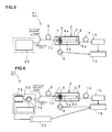
Fig. 5 is a schematic diagram showing the configuration of an optical spectrum analyzer according to a modification of the first embodiment. -
Fig. 6 is a schematic diagram illustrating the configuration of an optical spectrum analyzer according to a second embodiment of the invention. -
Fig. 7 is a schematic diagram illustrating the configuration of an optical spectrum analyzer according to a third embodiment of the invention. -
Fig. 8(a) and Fig. 8(b) are graphs showing a relationship between a SAW excitement frequency and a light output in the third embodiment and a relationship between the wavelength of selected light and a light output. -
Fig. 9 is a schematic diagram illustrating the configuration of an optical spectrum analyzer according to a modification of the third embodiment. -
- 1
- optical spectrum analyzer
- 2
- acousto-optic tunable filter
- 3
- piezoelectric substrate
- 4a, 4b
- optical waveguides
- 5
- IDT
- 6
- driving circuit
- 7, 8
- polarizing splitters
- 7a
- incident end
- 8a
- emitting end
- 9
- input optical fiber
- 10
- light source
- 11
- wideband light source
- 12
- optical circulator
- 13
- FBG
- 13a
- core layer
- 13b
- clad layer
- 13c
- different index layer
- 14
- output optical fiber
- 15
- photoreceiver
- 16
- arithmetic device
- 21
- optical spectrum analyzer
- 22
- laser source
- 31
- optical spectrum analyzer
- 32
- temperature detecting sensor
- 33
- temperature correcting device
- 41
- optical spectrum analyzer
- 42
- light source
- 43, 44
- FBG
- 45
- optical fiber
- 50
- wideband light source
- 51
- light sensor
- 52 to 54
- FBGs
- 55
- optical fiber
- 61
- optical spectrum analyzer
- 62, 63
- laser source
- The present invention will be clarified by describing specific embodiments of the present invention with reference to the drawings.
-
Fig. 1 is a schematic diagram of the configuration of an optical spectrum analyzer according to a first embodiment of the present invention. - The
optical spectrum analyzer 1 of the present invention includes a waveguide acousto-optictunable filter 2 to which light to be measured is input and from which selected light is output. The waveguide acousto-optictunable filter 2 is configured by using apiezoelectric substrate 3. In the present invention, thepiezoelectric substrate 3 is formed of a LiNbO3 piezoelectric monocrystal substrate. However, thepiezoelectric substrate 3 may be formed of a different piezoelectric monocrystal or may be formed of piezoelectric ceramic. - On the
piezoelectric substrate 3,optical waveguides 4a and 4b are provided. AnIDT 5 is provided in a part of theoptical waveguides 4a and 4b. TheIDT 5 is electrically connected to adriving circuit 6. TheIDT 5 consists of a pair of interdigitated comb electrodes having a plurality of electrode fingers. When a high frequency signal is applied to theIDT 5, theIDT 5 is excited and a surface acoustic wave is excited. This excitation of the surface acoustic wave converts a polarization mode of light that propagates in theoptical waveguides 4a and 4b in a single polarization mode. - In addition, a cross waveguide
polarizing splitter 7 is provided closer to an input side than theIDT 5, and a cross waveguidepolarizing splitter 8 is similarly provided on an output side of theoptical waveguides 4a and 4b. - The waveguide acousto-optic
tunable filter 2 that includes theoptical waveguides 4a and 4b, theIDT 5, and thepolarizing splitters - In the waveguide acousto-optic
tunable filter 2, which is a non-polarization-dependent AOTF, light to be measured, and reference light, which is described below, are incident on one incident end 7a of thepolarizing splitter 7 provided on an incident side. As described below, selected light is emitted from one emitting end 8a of the second cross waveguidepolarizing splitter 8. - The
IDT 5 can be formed of Al, Cu, or a proper metal or alloy. - Further, the
optical waveguides 4a and 4b, and the crosswaveguide polarizing splitters - In this embodiment, an incident optical fiber 9 is connected to the one incident end 7a of the waveguide acousto-optic
tunable filter 2. The light to be measured or the reference light is incident on the incident optical fiber 9. Here, the reference light is incident from alight source 10 on the incident optical fiber 9. Thelight source 10 includes a widebandlight source 11 having a relatively wide band (that is, the widebandlight source 11, which generates light having various wavelengths), anoptical circulator 12, and anFBG 13. TheFBG 13 is a fiber Bragg grating, and has a function of reflecting and emitting light having a predetermined wavelength. The wavelength of the reference light is outside a wavelength range in which the spectrum of the light to be measured is measured and is within a wavelength range that can be monitored by the AOTF. -
Fig. 2 is a schematic perspective view illustrating functions of theFBG 13. TheFBG 13 is provided as part of the optical fiber or is provided so as to be joined to the optical fiber. Similarly to the optical fiber, theFBG 13 has a core layer 13a, and a clad layer 13b provided around the core layer 13a. Similarly to the optical fiber, theFBG 13 has a refractive index difference between the core layer 13a and the clad layer 13b. In addition, in a part of the clad layer 13b, a different refractive index layer 13c having a refractive index different from that of the core layer 13a is provided at a predetermined pitch. Since the different refractive index layer 13c is provided at the predetermined pitch, as indicated by the arrow A, in the light that is incident, only light having a wavelength matching the pitch of the different refractive index layer 13c is reflected as indicated by the arrow B. In other words, only light having a particular wavelength is reflected as indicated by the arrow B, and light having other wavelengths is transmitted. - Referring back to
Fig. 1 , in this embodiment, in light which includes light having various wavelength components and which is incident from the widebandlight source 11 on anoptical circulator 12, only light having a particular wavelength is reflected by theFBG 13 and is given as the reference light to the input optical fiber 9. - Accordingly, since only light having a particular wavelength can be extracted by using the
FBG 13, for example, a wideband light source, such as an ASE light source, can be used as thelight source 11. - In addition, an
optical fiber 14 is connected to the emitting end 8a of the waveguide acousto-optictunable filter 2. Aphotoreceptor 15 is connected to an output side of theoptical fiber 14. Thephotoreceptor 15 is formed of, for example, a proper photoelectric conversion element such as a photodiode, and outputs an electric signal in accordance with the intensity of input light. - In this embodiment, an
arithmetic device 16 is electrically connected to thephotoreceptor 15. Also, thearithmetic device 16 is electrically connected to thedriving circuit 6. - The
arithmetic device 16 calculates a light output that is output in accordance with an electric signal given from thephotoreceptor 15. Also, as described below, on the basis of a relationship between the frequency of a high frequency signal that is applied in order to excite theIDT 5 and a known wavelength of the reference light, thearithmetic device 16 corrects a relationship between the frequency of the high frequency signal and the wavelength of selected light selected from the light to be measured, and gives a highly accurate optical spectrum. - An operation of the
optical spectrum analyzer 1 according to this embodiment will be described. In theoptical spectrum analyzer 1, the light to be measured is incident from the input optical fiber 9 on the one incident end 7a. In this case, the light to be measured includes light having various wavelength components. Accordingly, with theoptical spectrum analyzer 1, an output change dependent on the wavelength of light in a wavelength range, that is, a light output dependent on the frequency of light in a wavelength range, is measured. - More specifically, incident light is split by the
polarizing splitter 7 into TE mode light and TM mode light. The TE mode light or TM mode light is guided to one optical waveguide 4a, and the TM mode light or TE mode light is guided to the otheroptical waveguide 4b. In addition, by applying the high frequency signal from the drivingcircuit 6 to theIDT 5, theIDT 5 is excited and a surface acoustic wave is propagated. This propagation of the surface acoustic wave deforms a crystal structure of thepiezoelectric substrate 3, so that, among polarization modes in which propagation through theoptical waveguides 4a and 4b is performed in a single polarization mode, a polarization mode of polarization of a particular wavelength according to the frequency of an IDT driving high frequency signal is converted. - In other words, in a case where a high frequency signal having a frequency fa is applied from the driving
circuit 6 to theIDT 5, for example, when TE mode polarization is propagated through the optical waveguide 4a, in TE mode polarization, only a polarization mode of a wavelength having a particular wavelength λa is converted into the TM mode. The light having the mode changed in the above manner is separated from light having other wavelengths by thepolarizing splitter 8. The separated light is output as selected light from the emitting end 8a and is given to thephotoreceptor 15. - In this case, the frequency of the high frequency signal applied to the
IDT 5 and the wavelength of the selected light have a one-to-one relationship. - Thus, a high frequency signal in a frequency range according to a wavelength range is applied from the driving
circuit 6 to theIDT 5, while performing sweeping, and measurement is performed, whereby a light output change dependent on a wavelength in a wavelength range can be obtained. - However, although the frequency of the high frequency signal applied to the
IDT 5 and the wavelength of the selected light have a one-to-one relationship, a wavelength gradient dλ/df of the wavelength of the selected light to the frequency changes on the basis of the temperature. Here, dλ represents a change in wavelength of the selected light, and df represents a change of the high frequency signal. In other words, the relationship of the wavelength of the selected light with the frequency of the high frequency signal applied to theIDT 5 has temperature dependency. - Accordingly, when ambient temperature changes, there is a possibility that the wavelength of the selected light in the obtained optical spectrum may be shifted from an accurate wavelength.
- Conversely, in this embodiment, the reference light is incident from the
light source 10, and, on the basis of the result of the reference light, the wavelength of the selected light obtained from the light to be measured is corrected. - In other words, the reference light has a particular known wavelength determined by the
FBG 13. As indicated by the arrows inFig. 1 , the light to be measured and the reference light are simultaneously guided from the input optical fiber 9 to the waveguide acousto-optictunable filter 2. The guided light to be measured and reference light are polarized by thepolarizing splitter 7 into TE mode light and TM mode light. In this case, for example, a high frequency signal in a predetermined frequency range is applied from the drivingcircuit 6 to theIDT 5 so that step sweeping is performed. For example, a case is exemplified in which, by using reference light having a wavelength of 1545 nm at a temperature of 25°C, light to be measured having a wavelength in the vicinity of 1550 nm is measured. In this case, for example, an IDT exciting high frequency signal is step-swept in 171 MHz to 173 MHz. An example of an output waveform obtained from thephotoreceptor 15 is as shown inFig. 3(a) . The horizontal axis ofFig, 3(a) indicates the frequency of a high frequency signal, and the vertical axis indicates a light output. As is clear fromFig. 3(a) , two peaks appear on the light output. The arrow C denotes a peak responsive to reference light having a wavelength of 1545 nm, and the arrow D denotes a peak based on the light to be measured. - As is commonly known, the wavelength of selected light in an acousto-optic tunable filter is proportional to the reciprocal of a high frequency signal exciting an IDT. Accordingly, in the case of measuring reference light and light to be measured, as shown above, when the wavelength of the reference light is lower; the peak of the reference light appears on a side having a lower frequency of the high frequency signal. Therefore,
Fig. 3(a) indicates that what is denoted by the arrow C is the peak based on the reference light. However, in the case of using reference light having a particular wavelength, by measuring beforehand, at a temperature, the frequency of a high frequency signal responsive to a particular wavelength of the reference light, it can be determined which of two peaks inFig. 3(a) is based on the reference light. - In addition, although the frequency of the high frequency signal and the wavelength of selected light have a one-to-one relationship, as described above, a change in temperature changes dλ/df. In this embodiment, despite the change in dλ/df caused by the temperature, the optical spectrum can be measured with high accuracy. This will be described with reference to
Fig. 3(b) andFigs. 4(a) and (b) . -
Fig. 4(a) shows a gradient of wavelength change dλ of selected light to frequency change df of the high frequency signal. In other words,Fig. 4(a) shows a change caused by the temperature. As is clear fromFig. 4(a) , dλ/df is -8.55 nm/MHz at 25°C. Also, the frequency, which corresponds to a wavelength of 1545 nm as reference light, is known. Therefore, in thearithmetic device 16, the wavelength of selected light selected from light to be measured can be determined from the frequency of a high frequency signal on the basis of the relationship of the frequency of the high frequency signal to the wavelength of the reference light. In other words, the wavelength of selected light selected from light to be measured can be corrected on the basis of a relationship between the wavelength of reference light in a case where the reference light is incident, and a high frequency signal.Fig. 3(b) is a graph obtained by rewriting the optical spectrum shown inFig. 3(a) on the basis of the result of correcting a light wavelength by using the above dλ/df based on a result in a case where reference light is incident. - For example, it is assumed that light to be measured in the vicinity of 1550 nm be measured by using reference light having 1545 nm at a temperature of 35°C. In this case, if correction using the above dλ/df is not performed, the result indicated by the dotted line E in
Fig. 4(b) is obtained. Conversely, if correction using the above dλ/df is performed, correction is performed as indicated by the solid line F inFig. 4(b) . - Therefore, even if ambient temperature changes, the optical spectrum can be measured with higher accuracy.
- As described above, the reference light is used to correct the relationship between the exciting frequency and the wavelength of the selected light. Thus, it is necessary for the wavelength of the reference light to exist outside a wavelength range of the light to be measured.
-
Fig. 5 is a schematic block diagram of an optical analyzer according to a modification of the first embodiment. Theoptical spectrum analyzer 21 according to this modification is similar to that according to the first embodiment, except that alaser source 22 that emits a beam having a single wavelength is used instead of thelight source 10. As described above, instead of a configuration having the widebandlight source 11 and theFBG 13, by using thelaser source 22 that can emit a beam having a single wavelength, reference light can be given to the acousto-optictunable filter 2. In other words, in the present invention, regarding a light source that gives reference light, in addition to a light source apparatus using theFBG 13, various light sources that can emit a beam having a single wavelength, such as thelaser source 22, can be used, if necessary. -
Fig. 6 is a schematic block diagram of anoptical spectrum analyzer 31 according to a second embodiment of the present invention. - The
optical spectrum analyzer 31 is similar in configuration to the optical spectrum analyzer according to the first embodiment, except that it includes anFBG 13, atemperature sensor 32 that detects the temperature of a portion provided with theFBG 13, and atemperature correcting device 33 electrically connected to thetemperature sensor 32. - As described above, the
FBG 13 reflects and outputs a particular wavelength of light. However, the particular wavelength in theFBG 13 also has temperature dependency. In other words, theFBG 13 reflects and emits only light having a particular wavelength in input light. The particular wavelength changes with a temperature. In theoptical spectrum analyzer 31 according to the second embodiment, the temperature of theFBG 13 is detected by thetemperature sensor 32 serving as a temperature detecting device. The wavelength of the light reflected by theFBG 13 on the basis of the temperature, that is, a change in wavelength of reference light, is corrected by thetemperature correcting device 33, and the corrected light is given to thearithmetic device 16. Accordingly, in this embodiment, also the change in wavelength of the reference light on the basis of the temperature change is compensated. Thus, the optical spectrum can be measured with higher accuracy. - Although, in the second embodiment, the
temperature sensor 32 as a temperature detecting device and thetemperature correcting device 33 are used, for example, in order to thermoregulate the temperature of theFBG 13, a thermoregulator may be provided. In other words, a thermoregulator may be used so that the temperature of theFBG 13 is constant. In this case, reference light having an always constant wavelength can be given to the acousto-optictunable filter 2 without being corrected. - Such a thermoregulator is not particularly limited. A proper thermoregulator that includes a heater, a temperature sensor; and a controller that switches on and off the heater on the basis of a temperature measured by the temperature sensor can be used.
-
Fig. 7 is a schematic block diagram of the configuration of an optical spectrum analyzer according to a third embodiment of the present invention. The optical spectrum analyzer 41 is similar to the optical spectrum analyzer, except that it includes thelight source 50 shown inFig. 7 instead of thelight source 10 in the first embodiment, and that it is connected to an optical sensor 51 that is frequently used with optical spectrum analyzers. Accordingly, by denoting identical portions with identical reference numerals, their detailed description is omitted. - In this embodiment, the
light source 50, which has a relatively wide band, is provided as a light generator that generates light having various wavelengths. Thelight source 50 is used as a light source for giving reference light in the optical spectrum analyzer 41, and is also used as a light source for the optical sensor 51. In other words, thelight source 50 is shared by the optical spectrum analyzer 41 and the optical sensor 51. - The optical sensor 51 is a sensor that detects various physical quantities on the basis of light wavelengths and changes in strength, such as a sensor that detects a displacement based on deformation in the ground. The optical sensor 51 detects a change in light based on a change in target physical quantity. In the optical sensor 51, a plurality of
FBGs 52 to 54 are provided. TheFBGs 52 to 54 are configured to respectively reflect light having a wavelength of λ1, light having a wavelength of λ2, and light having a wavelength of λ3, and are connected to one another in series. - Thus, from the light incident from the wideband
light source 50 on theFBGs 52 to 54, the light having a wavelength of λ1, the light having a wavelength of λ2, and the light having a wavelength of λ3, that is, types of light having three wavelengths, can be used in the optical sensor 51. - In addition, in this embodiment, two types of light having two wavelengths are used as reference light that is given to the acousto-optic
tunable filter 2. Accordingly, theFBGs FBGs light source 50. Thus, from the light incident from thelight source 50, two types of light having wavelengths λa and λb are given as first reference light and second reference light to the acousto-optictunable filter 2. - In this embodiment, as described above, two types of reference light having particular wavelengths, a first wavelength of λa and a second wavelength λb, are given to the acousto-optic
tunable filter 2. By performing correction using plural types of reference light in this manner, the optical spectrum can be measured with higher accuracy. This will be described with reference toFig. 8(a) and (b) . - A case in which light in the vicinity of 1550 nm is incident as light to be measured on the optical spectrum analyzer 41 according to this embodiment, in order to measure the optical spectrum, is exemplified. In this case, the optical spectrum is measured similarly to the case of the first embodiment with first reference light wavelength λa = 1545 nm and second reference light wavelength λb = 1555 nm. As shown in
Fig. 8(a) , when the horizontal axis indicates the frequency of a high frequency signal that excites theIDT 5, three peaks G, H, and I appear. Here, relationships between the first and second light wavelengths λa and λb, and the exciting frequency are determined beforehand. Also, the wavelength of the selected light and the frequency of a corresponding high frequency signal are inversely proportional to each other. Accordingly, this indicates that peak G represents reference light having 1545 nm and that peak I represents reference light having 1555 nm. In addition, peak H is a peak of the light to be measured. - Meanwhile, as described above, dλ/df has temperature dependency. As in the case of the first embodiment, in a case where the dλ/df is corrected by using single reference light, the correspondence between the reference light wavelength and the exciting frequency can be ascertained only at one point. However; since dλ/df itself is unknown, it is unclear that to which light wavelength range a sweeping range of the high frequency signal frequency corresponds. Accordingly, in the case of the first embodiment, it is preferable that, after a temperature characteristic of an acousto-optic tunable filter is ascertained beforehand, a change in corresponding dλ/df be determined, while monitoring the temperature in the case of measurement.
- Compared with this, since this embodiment uses the first reference light having a wavelength λa and the second reference light having a wavelength λb, a relationship between the wavelength of the selected light and the exciting frequency can be ascertained at two points. Therefore, simultaneously with measurement, dλ/df itself can be determined on the basis of a gradient between the two points. In other words, as
Fig. 8(b) shows results obtained by converting the exciting frequency into the wavelength of selected light, a wavelength corresponding to the two types of reference light can be known. Thus, also a wavelength in another wavelength range can be accurately ascertained. Hence, an optical spectrum can be detected with high accuracy without providing a complex temperature adjusting device or temperature monitoring device. - In addition, in particular, in the case of using two types of reference light, it is preferable that the wavelength λa of the reference light and wavelength λb be dispersed on low-frequency and high-frequency sides of the wavelength range of the light to be measured. This makes it possible to perform more accurate temperature correction in the wavelength range of the light to be measured.
- Also, in this embodiment, the optical spectrum analyzer 41 shares the light source with the optical sensor 51. Thus, in the optical spectrum analyzer used with the optical sensor device, a reduced number of components, cost reduction, and size reduction can be achieved. The light source of the optical spectrum analyzer in the optical sensor 51 can be shared with the optical sensor 51, and can be also used with an apparatus light source.
-
Fig. 9 is a schematic block diagram showing a modification of the spectrum analyzer according to the third embodiment. In the above embodiment, thelight source 50 is used with the optical sensor 51. In this modification, two types of reference light are given to the waveguide acousto-optictunable filter 2 by using two types oflaser sources optical spectrum analyzer 63 according to the modification, when plural types of reference light are given, laser sources according to the types of reference light may be used as light sources.
Claims (5)
- An optical spectrum analyzer for detecting a light output that is dependent on the frequency of light in a wavelength range of light to be measured, comprising:a waveguide acousto-optic tunable filter including a piezoelectric substrate, an optical waveguide provided on the piezoelectric substrate, and an IDT for converting the mode of light being propagated in the optical waveguide;a light source for giving, to the waveguide acousto-optic tunable filter, reference light having a particular wavelength outside the wavelength range;a driving circuit for exciting the IDT of the waveguide acousto-optic tunable filter by supplying a high frequency signal;a photoreceptor that receives light that is output from the waveguide acousto-optic tunable filter; andan arithmetic device in which, on the basis of:a relationship between the frequency of the high frequency waves applied to the IDT and the wavelength of selected light selected from the light to be measured is corrected.the wavelength of selected light that is output when the mode of reference light is converted by causing the reference light to be incident on the waveguide acousto-optic tunable filter and applying high frequency waves having a predetermined frequency to the IDT, andthe predetermined frequency, at which the IDT is excited,
- The optical spectrum analyzer according to Claim 1, wherein the light source includes a light generator that generates light having various wavelengths, and a fiber Bragg grating that enables, from the light given from the light generator, output of only light having a particular wavelength.
- The optical spectrum analyzer according to Claim 1, wherein the light source is a laser source.
- The optical spectrum analyzer according to any one of Claims 1 to 3, wherein the light source is configured so that first and second types of light having different wavelengths are given as the reference light, and a relationship between the frequency of the high frequency waves applied to the IDT and the wavelength of the selected light is corrected by the first and second types of light.
- The optical spectrum analyzer according to any one of Claims 1, 2, and 4, for use in combination with an optical sensor for detecting a predetermined physical quantity,
wherein the optical sensor includes a light source and an optical detecting unit, and the light source of the optical spectrum analyzer is shared with the light source of the optical sensor.
Applications Claiming Priority (2)
| Application Number | Priority Date | Filing Date | Title |
|---|---|---|---|
| JP2006008312 | 2006-01-17 | ||
| PCT/JP2007/050461 WO2007083609A1 (en) | 2006-01-17 | 2007-01-16 | Light spectrum analyzer |
Publications (2)
| Publication Number | Publication Date |
|---|---|
| EP1975579A1 true EP1975579A1 (en) | 2008-10-01 |
| EP1975579A4 EP1975579A4 (en) | 2012-11-28 |
Family
ID=38287562
Family Applications (1)
| Application Number | Title | Priority Date | Filing Date |
|---|---|---|---|
| EP07713610A Withdrawn EP1975579A4 (en) | 2006-01-17 | 2007-01-16 | Optical spectrum analyzer |
Country Status (4)
| Country | Link |
|---|---|
| US (1) | US7609383B2 (en) |
| EP (1) | EP1975579A4 (en) |
| JP (1) | JPWO2007083609A1 (en) |
| WO (1) | WO2007083609A1 (en) |
Families Citing this family (5)
| Publication number | Priority date | Publication date | Assignee | Title |
|---|---|---|---|---|
| JPWO2008152879A1 (en) * | 2007-06-12 | 2010-08-26 | 株式会社村田製作所 | Optical spectrum analyzer |
| WO2009054193A1 (en) * | 2007-10-26 | 2009-04-30 | Murata Manufacturing Co., Ltd. | Optical spectrum analyzer |
| WO2018056208A1 (en) * | 2016-09-20 | 2018-03-29 | 長野計器株式会社 | Light wavelength measurement device |
| CN107084787A (en) * | 2017-03-08 | 2017-08-22 | 北京环境特性研究所 | A kind of temperature correction of AOTF imaging spectrometers spectral calibration |
| CN108872159A (en) * | 2018-08-20 | 2018-11-23 | 中国科学院上海技术物理研究所 | A kind of spectrum detection instrument and its method measuring liquid component spectral characteristic |
Family Cites Families (8)
| Publication number | Priority date | Publication date | Assignee | Title |
|---|---|---|---|---|
| JPH0816747B2 (en) * | 1988-07-19 | 1996-02-21 | 富士写真フイルム株式会社 | Optical spectrum analyzer |
| JPH02194337A (en) * | 1989-01-23 | 1990-07-31 | Fuji Photo Film Co Ltd | Optical spectrum analyzer |
| JP2001264167A (en) | 2000-03-16 | 2001-09-26 | Nippon Telegr & Teleph Corp <Ntt> | Optical spectrum analyzer |
| JP4270718B2 (en) * | 2000-04-27 | 2009-06-03 | 株式会社アドバンテスト | Reference wavelength light generator |
| JP2002214459A (en) | 2001-01-15 | 2002-07-31 | Nippon Telegr & Teleph Corp <Ntt> | Wavelength spectrometer and optical spectrum analyzer |
| US6687001B2 (en) * | 2001-03-16 | 2004-02-03 | Fujitsu Limited | Optical spectrum analyzer and optical spectrum detecting method |
| JP3761025B2 (en) * | 2002-08-22 | 2006-03-29 | 横河電機株式会社 | Optical spectrum analyzer |
| JP2007178258A (en) | 2005-12-28 | 2007-07-12 | Yokogawa Electric Corp | Optical spectrum analyzer and optical fiber sensor system using the same |
-
2007
- 2007-01-16 WO PCT/JP2007/050461 patent/WO2007083609A1/en not_active Ceased
- 2007-01-16 JP JP2007554885A patent/JPWO2007083609A1/en active Pending
- 2007-01-16 EP EP07713610A patent/EP1975579A4/en not_active Withdrawn
-
2008
- 2008-07-01 US US12/165,721 patent/US7609383B2/en active Active
Also Published As
| Publication number | Publication date |
|---|---|
| US20080259332A1 (en) | 2008-10-23 |
| WO2007083609A1 (en) | 2007-07-26 |
| EP1975579A4 (en) | 2012-11-28 |
| US7609383B2 (en) | 2009-10-27 |
| JPWO2007083609A1 (en) | 2009-06-11 |
Similar Documents
| Publication | Publication Date | Title |
|---|---|---|
| EP1760424B1 (en) | Distributed optical fiber sensor | |
| US8857242B2 (en) | Photoacoustic gas sensor and its use | |
| US7268884B2 (en) | Wavelength reference system for optical measurements | |
| US9146095B2 (en) | FBG vibration detection system, apparatus and vibration detection method using the system | |
| US20080043243A1 (en) | AE/ultrasound detection system, and material monitoring apparatus and nondestructive inspection apparatus equipped the system | |
| US8693512B2 (en) | Frequency referencing for tunable lasers | |
| US7609383B2 (en) | Optical spectrum analyzer | |
| CN101479577B (en) | Method for monitoring and measuring optical properties of devices in polarization-maintaining optical fibers using reference fiber Bragg gratings and optical fiber components fabricated therefrom | |
| CN101604055A (en) | A Parallel Dual-Cavity Tunable Fiber Fabry-Perot Filter | |
| WO2001061303A1 (en) | Polarization mode dispersion measuring device and polarization mode dispersion measuring method | |
| JP4758227B2 (en) | Distributed optical fiber sensor | |
| JP3934544B2 (en) | Elastic wave observation device | |
| JP4027352B2 (en) | Optical fiber probe device | |
| CN102735270B (en) | Wavelength-scanning-based active fiber Bragg grating time domain demodulating device | |
| CN104697634A (en) | Very high resolution spectral measurement device and method | |
| JPWO2008152879A1 (en) | Optical spectrum analyzer | |
| JP2005114512A (en) | Strain measuring apparatus and wavelength correction method | |
| JP2004205271A (en) | Wavelength meter and FBG sensing device using the same | |
| RU2520963C2 (en) | Optic fibre measuring system (versions) | |
| Álvarez-Ocampo et al. | Forward Stimulated Brillouin Scattering for point-to-point sensing and metrology | |
| Dashti et al. | Measurement of acoustic wavelength in optical fiber via acousto-optic interaction | |
| JPH0953999A (en) | Optical external force detector | |
| Tanaka et al. | Application of acoustooptic tunable filter to strain-or vibration-sensing system | |
| JP4004921B2 (en) | Load monitoring apparatus and load monitoring method | |
| WO2025182120A1 (en) | Inspection device and inspection method |
Legal Events
| Date | Code | Title | Description |
|---|---|---|---|
| PUAI | Public reference made under article 153(3) epc to a published international application that has entered the european phase |
Free format text: ORIGINAL CODE: 0009012 |
|
| 17P | Request for examination filed |
Effective date: 20080626 |
|
| AK | Designated contracting states |
Kind code of ref document: A1 Designated state(s): AT BE BG CH CY CZ DE DK EE ES FI FR GB GR HU IE IS IT LI LT LU LV MC NL PL PT RO SE SI SK TR |
|
| DAX | Request for extension of the european patent (deleted) | ||
| A4 | Supplementary search report drawn up and despatched |
Effective date: 20121031 |
|
| RIC1 | Information provided on ipc code assigned before grant |
Ipc: G01J 3/18 20060101AFI20121025BHEP Ipc: G01J 9/00 20060101ALI20121025BHEP |
|
| STAA | Information on the status of an ep patent application or granted ep patent |
Free format text: STATUS: THE APPLICATION IS DEEMED TO BE WITHDRAWN |
|
| 18D | Application deemed to be withdrawn |
Effective date: 20130530 |