EP1975513A2 - A premix burner for a gas turbine, in particular a microturbine - Google Patents
A premix burner for a gas turbine, in particular a microturbine Download PDFInfo
- Publication number
- EP1975513A2 EP1975513A2 EP20080152724 EP08152724A EP1975513A2 EP 1975513 A2 EP1975513 A2 EP 1975513A2 EP 20080152724 EP20080152724 EP 20080152724 EP 08152724 A EP08152724 A EP 08152724A EP 1975513 A2 EP1975513 A2 EP 1975513A2
- Authority
- EP
- European Patent Office
- Prior art keywords
- annular duct
- respect
- longitudinal axis
- main
- burner according
- Prior art date
- Legal status (The legal status is an assumption and is not a legal conclusion. Google has not performed a legal analysis and makes no representation as to the accuracy of the status listed.)
- Withdrawn
Links
- 238000002485 combustion reaction Methods 0.000 claims abstract description 26
- 238000009792 diffusion process Methods 0.000 claims description 4
- 230000000284 resting effect Effects 0.000 claims description 3
- 239000007789 gas Substances 0.000 description 27
- 239000000203 mixture Substances 0.000 description 7
- 239000001257 hydrogen Substances 0.000 description 3
- 229910052739 hydrogen Inorganic materials 0.000 description 3
- MWUXSHHQAYIFBG-UHFFFAOYSA-N nitrogen oxide Inorganic materials O=[N] MWUXSHHQAYIFBG-UHFFFAOYSA-N 0.000 description 3
- 206010016754 Flashback Diseases 0.000 description 2
- UFHFLCQGNIYNRP-UHFFFAOYSA-N Hydrogen Chemical compound [H][H] UFHFLCQGNIYNRP-UHFFFAOYSA-N 0.000 description 2
- 239000012530 fluid Substances 0.000 description 2
- 239000003517 fume Substances 0.000 description 2
- VNWKTOKETHGBQD-UHFFFAOYSA-N methane Chemical compound C VNWKTOKETHGBQD-UHFFFAOYSA-N 0.000 description 2
- 238000000034 method Methods 0.000 description 2
- 230000001133 acceleration Effects 0.000 description 1
- 239000010426 asphalt Substances 0.000 description 1
- 230000015572 biosynthetic process Effects 0.000 description 1
- 239000003245 coal Substances 0.000 description 1
- 238000001816 cooling Methods 0.000 description 1
- 230000007423 decrease Effects 0.000 description 1
- 239000000295 fuel oil Substances 0.000 description 1
- 238000002309 gasification Methods 0.000 description 1
- 150000002431 hydrogen Chemical class 0.000 description 1
- 238000002156 mixing Methods 0.000 description 1
- 238000012986 modification Methods 0.000 description 1
- 230000004048 modification Effects 0.000 description 1
- 239000003345 natural gas Substances 0.000 description 1
- 239000003921 oil Substances 0.000 description 1
- 238000013021 overheating Methods 0.000 description 1
- 230000002265 prevention Effects 0.000 description 1
- 230000000087 stabilizing effect Effects 0.000 description 1
- 238000003786 synthesis reaction Methods 0.000 description 1
- 238000011144 upstream manufacturing Methods 0.000 description 1
Images

Classifications
-
- F—MECHANICAL ENGINEERING; LIGHTING; HEATING; WEAPONS; BLASTING
- F23—COMBUSTION APPARATUS; COMBUSTION PROCESSES
- F23R—GENERATING COMBUSTION PRODUCTS OF HIGH PRESSURE OR HIGH VELOCITY, e.g. GAS-TURBINE COMBUSTION CHAMBERS
- F23R3/00—Continuous combustion chambers using liquid or gaseous fuel
- F23R3/28—Continuous combustion chambers using liquid or gaseous fuel characterised by the fuel supply
- F23R3/286—Continuous combustion chambers using liquid or gaseous fuel characterised by the fuel supply having fuel-air premixing devices
-
- F—MECHANICAL ENGINEERING; LIGHTING; HEATING; WEAPONS; BLASTING
- F23—COMBUSTION APPARATUS; COMBUSTION PROCESSES
- F23R—GENERATING COMBUSTION PRODUCTS OF HIGH PRESSURE OR HIGH VELOCITY, e.g. GAS-TURBINE COMBUSTION CHAMBERS
- F23R3/00—Continuous combustion chambers using liquid or gaseous fuel
- F23R3/02—Continuous combustion chambers using liquid or gaseous fuel characterised by the air-flow or gas-flow configuration
- F23R3/04—Air inlet arrangements
- F23R3/10—Air inlet arrangements for primary air
- F23R3/12—Air inlet arrangements for primary air inducing a vortex
- F23R3/14—Air inlet arrangements for primary air inducing a vortex by using swirl vanes
-
- F—MECHANICAL ENGINEERING; LIGHTING; HEATING; WEAPONS; BLASTING
- F23—COMBUSTION APPARATUS; COMBUSTION PROCESSES
- F23C—METHODS OR APPARATUS FOR COMBUSTION USING FLUID FUEL OR SOLID FUEL SUSPENDED IN A CARRIER GAS OR AIR
- F23C2900/00—Special features of, or arrangements for combustion apparatus using fluid fuels or solid fuels suspended in air; Combustion processes therefor
- F23C2900/03001—Miniaturized combustion devices using fluid fuels
-
- F—MECHANICAL ENGINEERING; LIGHTING; HEATING; WEAPONS; BLASTING
- F23—COMBUSTION APPARATUS; COMBUSTION PROCESSES
- F23R—GENERATING COMBUSTION PRODUCTS OF HIGH PRESSURE OR HIGH VELOCITY, e.g. GAS-TURBINE COMBUSTION CHAMBERS
- F23R2900/00—Special features of, or arrangements for continuous combustion chambers; Combustion processes therefor
- F23R2900/00002—Gas turbine combustors adapted for fuels having low heating value [LHV]
Definitions
- the present invention relates to a premix burner for a gas turbine, of the type described in the US patent No. 6,374,615 , on which the preamble of Claim 1 is based.
- premix burners the combustible gas and the combustion air are mixed together before entering the combustion chamber with a marked excess of air with respect to the stoichiometric ratio in order to maintain the emissions of nitrogen oxides at discharge low.
- the need is felt to provide a premix burner for microturbines, i.e., turbines that drive electric-power generators with a power of between 10 and 500 kW, and to use as combustible gas a low-grade gas, for example a synthesis gas (syngas), which derives from processes of gasification of biomasses, of residue of refinery processes (asphalt, heavy oils), or of coal (the calorific value of said gas could be equal to one fifth of the calorific value of natural gas).
- a synthesis gas syngas
- the need is felt to use low-grade combustible gases having a high percentage of hydrogen without causing drawbacks in combustion, such as, for example, self-ignition or flash-back.
- the aim of the present invention is to provide a gas turbine premix burner that will enable the needs set forth above to be achieved in a simple and inexpensive way.
- a gas turbine premix burner comprising:
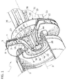
- FIG. 1 designated as a whole by 1 is a burner (shown with parts in cutaway view) for a gas turbine defined by a microturbine (not shown).
- the burner 1 produces a premix flame in a combustion chamber 2, extends along a rectilinear axis 3, coaxial to the chamber 2, and comprises a plate 4, which is substantially circular, is orthogonal to the axis 3, and carries, on a front face 5 of its own, an annular duct 7.
- the duct 7 has: a radial inlet 8, through which combustion air enters; and a substantially axial outlet 9, through which a mixture of combustible gas and combustion air gives out into the chamber 2.
- the duct 7 comprises an initial portion 10, which extends radially towards the axis 3 starting from the inlet 8 and is defined by an interchangeable ring 11, preferably constituted by two half-rings set alongside one another in a radial direction.
- the ring 11 comprises two annular plates 13, 14 parallel to the plate 4 and a blading 12, referred to generally as “swirler”, which is set axially between the plates 13, 14, is formed by so-called “thin” blades and bestows a tangential component and, hence, a vorticous motion on the combustion air.
- the duct 7 then comprises an elbow-shaped intermediate portion 15 and a final portion 16, which ends in a position corresponding to the outlet 9 and defines a mean path converging towards the axis 3.
- the portions 15 and 16 are defined by two walls 17 and 18 facing one another and having internal surfaces that extend as prolongations of those of the plates 13, 14.
- the plate 13 and the wall 17 are set alongside one another and are set resting on the face 5, whilst the wall 18 ends with an annular fin 21 that covers the plate 14.
- the plate 4 carries a central cylinder 22, which ends with a conical portion 23 diverging with respect to the axis 3 and defining a so-called "flame holder".
- the inside of the cylinder 22 is empty, but could possibly house a nozzle for combustible oil to be used as an alternative to the combustible gas.
- the cylinder 22, the wall 17, and the plate 4 delimit with one another an annular duct 24, which is concentric with the duct 7, receives combustion air through holes 25 made along a circumference through the plate 4, has an axial annular outlet 26 set flush with the outlet 9, and houses the end 28 of a ignition device 29, which extends through the plate 4.
- the end 28 is axially set back with respect to the outlet 26 so that it is not substantially lapped by hot fumes. Furthermore, the air that flows in the duct 24 automatically cools the end 28.
- the burner 1 comprises two lines 31, 32 for supply of combustible gas, comprising respective manifolds 33, 34, which receive the gas from respective pipings 35, 36.
- the manifolds 33, 34 are axially resting on the plate 4, on the opposite side with respect to the face 5, are concentric with respect to one another, are fixed to the plate 4 in a way not shown, and define radially with respect to one another a space 37 in which the combustion air flows towards the holes 25.
- the manifold 33 is radially external with respect to the manifold 34 and communicates with the duct 7 via a plurality of channels 38 defined by respective pipes 39, which are angularly set at equal distances apart from one another about the axis 3, are arranged downstream of the blading 12, are fixed with respect to the manifold 33, and extend through the plate 4 and the wall 17 along respective axes 40 parallel to the axis 3.
- the channels 38 are axially blind, in so far as the pipes 39 end against the wall 18, and have respective outlets defined, for each pipe 39, by a series of holes 41 ( Figure 2 ) axially aligned with respect to one another and directed radially towards the axis 3.
- the gas coming out of the holes 41 mixes with the air of the duct 7 and causes the premix flame.
- the duct 7 defines a convergent nozzle having a dimension, along the axis 3, comprised between 85% and 95% of the entire axial dimension of the duct 7. Just one final portion of the duct 7 does not define part of the aforesaid convergent nozzle; said final portion has a dimension, along the axis 3, equal to the remaining part of the duct 7 (for example, 5 mm).
- the dimension of the cross section of passage i.e., the section orthogonal to the mean path of the fluid between the internal surfaces of the duct 7) progressively decreases starting from the inlet 8.
- the air and then the mixture of air and gas are accelerated progressively up to the final portion of the duct 7, where the cross section of passage has a constant area or else is divergent.
- a possible expansion of the mixture is limited to the final portion of the duct 7, which is extremely short, so that phenomena of over-heating of the walls 17, 18 are prevented in the portion 16 and advantages of a fluid-dynamic type are experimentally encountered in the flow of the mixture entering the combustion chamber.
- the acceleration of the fluid and, hence, the profile of the duct 7 are established beforehand so as to bestow upon the mixture, at the outlet 9, an axial speed higher than the speed of flash-back and so as to have a time of passage in the duct 7 of the mixture shorter than the time of self-ignition of the mixture itself.
- the manifold 34 instead, is set along the axis 3, has a lateral recess 43 for passage of the device 29, and communicates with the chamber 2 via a plurality of pipes 44, which are set at equal angular distances apart from one another about the axis 3, are fixed with respect to the manifold 34, are arranged radially between the holes 25 and the cylinder 22, and extend through the plate 4 and in the duct 24 along respective axes 45 parallel to the axis 3.
- the gas coming out of the pipes 44 and the combustion air coming out of the duct 24 generate a diffusion flame, which is used as pilot flame for stabilizing the premix flame, for ignition of the burner 1, and for the partial loads.
- the pipes 44 have respective axial outlets 46 that are set flush with the outlet 26 so that no combustion pre-chamber is envisaged for the diffusion flame. There is thus avoided the need for additional cooling systems that would be necessary for said pre-chamber.
- the burner 1 In operation, it is possible to use in the burner 1 even a combustible gas defined by a low-grade gas, for example a syngas, having a relatively high percentage of hydrogen, without causing drawbacks in combustion.
- a combustible gas defined by a low-grade gas for example a syngas
- the burner 1 In order to perform said replacement, the burner 1 is dismantled in a relatively simple way by moving the plate 4 axially away from the duct 7 (consequently, by sliding the pipes 39 out of the duct 7) and removing the ring 11 from the remaining part of the duct 11.
- the burner 1 can be assembled and disassembled in a relatively simple way thanks to the characteristics and to the position of the plate 4 and of the ring 11 so that the burner 1 and, hence, the characteristics of combustion can be adapted to the characteristics of the combustible gas available at inlet.
- the profile of the duct 7 and the configuration of the pipes 39 enable prevention of undesirable phenomena of combustion.
- the pipes 39 are set in an area where vortex shedding is practically insignificant so that the head losses are low in the area of introduction of the gas.
- the fact of having the blading 12 set upstream of the pipes 39 and the fact of envisaging holes 41 with a radial component with respect to the axes 40 enable optimal mixing of the combustible gas in the duct 7 with the combustion air coming from the inlet 8, after the diameter, number, and position of the holes 41 has been appropriately set.
- the configuration of the outlets 9, 26 and 46 prevent entry of hot fumes into the ducts 24 and 7.
- the burner 1 has contained dimensions and, hence, can be also used for microturbines.
- the profiles of the ducts 7 and 24 could be different from the ones shown.
Landscapes
- Engineering & Computer Science (AREA)
- Chemical & Material Sciences (AREA)
- Combustion & Propulsion (AREA)
- Mechanical Engineering (AREA)
- General Engineering & Computer Science (AREA)
- Gas Burners (AREA)
Abstract
Description
- The present invention relates to a premix burner for a gas turbine, of the type described in the
US patent No. 6,374,615 , on which the preamble ofClaim 1 is based. - As is known, in premix burners the combustible gas and the combustion air are mixed together before entering the combustion chamber with a marked excess of air with respect to the stoichiometric ratio in order to maintain the emissions of nitrogen oxides at discharge low.
- The need is felt to provide a premix burner for microturbines, i.e., turbines that drive electric-power generators with a power of between 10 and 500 kW, and to use as combustible gas a low-grade gas, for example a synthesis gas (syngas), which derives from processes of gasification of biomasses, of residue of refinery processes (asphalt, heavy oils), or of coal (the calorific value of said gas could be equal to one fifth of the calorific value of natural gas). In particular, the need is felt to use low-grade combustible gases having a high percentage of hydrogen without causing drawbacks in combustion, such as, for example, self-ignition or flash-back.
- The aim of the present invention is to provide a gas turbine premix burner that will enable the needs set forth above to be achieved in a simple and inexpensive way.
- Provided according to the present invention is a gas turbine premix burner comprising:
- a main annular duct and a secondary annular duct concentric with respect to a longitudinal axis and having respective inlets for combustion air and respective axial outlets, which give out, in use, into a combustion chamber; the main annular duct comprising an initial portion that is radial with respect to said longitudinal axis and houses a blading generating vortices;
- a main line for feeding combustible gas into said main annular duct so as to generate a premix flame in said combustion chamber; and
- a secondary line for feeding combustible gas and generating a diffusion flame with the combustion air of said secondary annular duct;
- The invention will now be described with reference to the annexed plates of drawings, which show a non-limiting example of embodiment thereof, and in which:
-
Figure 1 shows, in perspective view and with parts in cutaway view, a preferred embodiment of the premix burner of a gas turbine according to the present invention; and -
Figure 2 is a cross section according to a radial plane, at an enlarged scale, of the burner ofFigure 1 . - In
Figure 1 , designated as a whole by 1 is a burner (shown with parts in cutaway view) for a gas turbine defined by a microturbine (not shown). Theburner 1 produces a premix flame in acombustion chamber 2, extends along arectilinear axis 3, coaxial to thechamber 2, and comprises a plate 4, which is substantially circular, is orthogonal to theaxis 3, and carries, on afront face 5 of its own, an annular duct 7. - The duct 7 has: a radial inlet 8, through which combustion air enters; and a substantially
axial outlet 9, through which a mixture of combustible gas and combustion air gives out into thechamber 2. - With reference to
Figure 2 , the duct 7 comprises aninitial portion 10, which extends radially towards theaxis 3 starting from the inlet 8 and is defined by aninterchangeable ring 11, preferably constituted by two half-rings set alongside one another in a radial direction. Thering 11 comprises twoannular plates blading 12, referred to generally as "swirler", which is set axially between theplates intermediate portion 15 and afinal portion 16, which ends in a position corresponding to theoutlet 9 and defines a mean path converging towards theaxis 3. Theportions walls plates plate 13 and thewall 17 are set alongside one another and are set resting on theface 5, whilst thewall 18 ends with anannular fin 21 that covers theplate 14. - The plate 4 carries a
central cylinder 22, which ends with aconical portion 23 diverging with respect to theaxis 3 and defining a so-called "flame holder". The inside of thecylinder 22 is empty, but could possibly house a nozzle for combustible oil to be used as an alternative to the combustible gas. - The
cylinder 22, thewall 17, and the plate 4 delimit with one another anannular duct 24, which is concentric with the duct 7, receives combustion air throughholes 25 made along a circumference through the plate 4, has an axialannular outlet 26 set flush with theoutlet 9, and houses theend 28 of aignition device 29, which extends through the plate 4. In particular, theend 28 is axially set back with respect to theoutlet 26 so that it is not substantially lapped by hot fumes. Furthermore, the air that flows in theduct 24 automatically cools theend 28. - With reference to the attached figures, the
burner 1 comprises twolines respective manifolds respective pipings - The
manifolds face 5, are concentric with respect to one another, are fixed to the plate 4 in a way not shown, and define radially with respect to one another aspace 37 in which the combustion air flows towards theholes 25. - The
manifold 33 is radially external with respect to themanifold 34 and communicates with the duct 7 via a plurality ofchannels 38 defined byrespective pipes 39, which are angularly set at equal distances apart from one another about theaxis 3, are arranged downstream of theblading 12, are fixed with respect to themanifold 33, and extend through the plate 4 and thewall 17 alongrespective axes 40 parallel to theaxis 3. Thechannels 38 are axially blind, in so far as thepipes 39 end against thewall 18, and have respective outlets defined, for eachpipe 39, by a series of holes 41 (Figure 2 ) axially aligned with respect to one another and directed radially towards theaxis 3. - The gas coming out of the
holes 41 mixes with the air of the duct 7 and causes the premix flame. The duct 7 defines a convergent nozzle having a dimension, along theaxis 3, comprised between 85% and 95% of the entire axial dimension of the duct 7. Just one final portion of the duct 7 does not define part of the aforesaid convergent nozzle; said final portion has a dimension, along theaxis 3, equal to the remaining part of the duct 7 (for example, 5 mm). - In the aforesaid convergent nozzle, the dimension of the cross section of passage (i.e., the section orthogonal to the mean path of the fluid between the internal surfaces of the duct 7) progressively decreases starting from the inlet 8. The air and then the mixture of air and gas are accelerated progressively up to the final portion of the duct 7, where the cross section of passage has a constant area or else is divergent. In this way, a possible expansion of the mixture is limited to the final portion of the duct 7, which is extremely short, so that phenomena of over-heating of the
walls portion 16 and advantages of a fluid-dynamic type are experimentally encountered in the flow of the mixture entering the combustion chamber. - The acceleration of the fluid and, hence, the profile of the duct 7 are established beforehand so as to bestow upon the mixture, at the
outlet 9, an axial speed higher than the speed of flash-back and so as to have a time of passage in the duct 7 of the mixture shorter than the time of self-ignition of the mixture itself. - The
manifold 34, instead, is set along theaxis 3, has alateral recess 43 for passage of thedevice 29, and communicates with thechamber 2 via a plurality ofpipes 44, which are set at equal angular distances apart from one another about theaxis 3, are fixed with respect to themanifold 34, are arranged radially between theholes 25 and thecylinder 22, and extend through the plate 4 and in theduct 24 alongrespective axes 45 parallel to theaxis 3. - The gas coming out of the
pipes 44 and the combustion air coming out of theduct 24 generate a diffusion flame, which is used as pilot flame for stabilizing the premix flame, for ignition of theburner 1, and for the partial loads. In particular, thepipes 44 have respectiveaxial outlets 46 that are set flush with theoutlet 26 so that no combustion pre-chamber is envisaged for the diffusion flame. There is thus avoided the need for additional cooling systems that would be necessary for said pre-chamber. - In operation, it is possible to use in the
burner 1 even a combustible gas defined by a low-grade gas, for example a syngas, having a relatively high percentage of hydrogen, without causing drawbacks in combustion. In particular, it is possible to convert theburner 1 so that it will be able to use combustible gases having a calorific value different from one another according to the availability: in particular, it is necessary to replace theblading 12 and/or thepipes 39. In order to perform said replacement, theburner 1 is dismantled in a relatively simple way by moving the plate 4 axially away from the duct 7 (consequently, by sliding thepipes 39 out of the duct 7) and removing thering 11 from the remaining part of theduct 11. In other words, theburner 1 can be assembled and disassembled in a relatively simple way thanks to the characteristics and to the position of the plate 4 and of thering 11 so that theburner 1 and, hence, the characteristics of combustion can be adapted to the characteristics of the combustible gas available at inlet. - Using combustible gas with high hydrogen content, the profile of the duct 7 and the configuration of the
pipes 39 enable prevention of undesirable phenomena of combustion. Thepipes 39 are set in an area where vortex shedding is practically insignificant so that the head losses are low in the area of introduction of the gas. In addition, the fact of having theblading 12 set upstream of thepipes 39 and the fact of envisagingholes 41 with a radial component with respect to theaxes 40 enable optimal mixing of the combustible gas in the duct 7 with the combustion air coming from the inlet 8, after the diameter, number, and position of theholes 41 has been appropriately set. At the same time, the configuration of theoutlets ducts 24 and 7. - Furthermore, it is evident how the
burner 1 has contained dimensions and, hence, can be also used for microturbines. - Finally, from the foregoing description it is, evident that modifications and variations can be made to the
burner 1 described with reference to the attached figures, without thereby departing from the sphere of protection of the present invention as defined by the annexed claims. - In particular, the profiles of the
ducts 7 and 24 could be different from the ones shown.
Claims (10)
- A gas turbine premix burner (1) comprising:- a main annular duct (7) and a secondary annular duct (24) concentric with respect to a longitudinal axis (3) and having respective inlets (8, 25) for the combustion air and respective axial outlets (9, 26), which give out, in use, into a combustion chamber (2); the main annular duct (7) comprising an initial portion (10), which is radial with respect to said longitudinal axis (3) and houses a blading (12) generating vortices;- a main line (31) for feeding combustible gas into said main annular duct (7) so as to generate a premix flame in said combustion chamber (2); and- a secondary line (32) for feeding combustible gas and generating a diffusion flame with the combustion air of said secondary annular duct (24);characterized in that said main line (31) comprises first pipes (39) housed in said main annular duct (7) about said longitudinal axis (3) and downstream of said blading (12), and having, each, at least one outlet hole (41) with a radial component with respect to the axis (40) of the first pipe (39).
- The burner according to Claim 1, characterized in that said main annular duct (7) comprises:- a convergent nozzle extending from the inlet (8) of said main annular duct (7) and having a dimension, along said longitudinal axis (3), comprised between 85% and 95% of the entire axial dimension of said main annular duct (7); and- a final portion, different from a convergent nozzle and having a dimension, along said longitudinal axis (3), equal to the remaining part of the entire axial dimension of said main annular duct (7).
- The burner according to Claim 1 or Claim 2,
characterized in that said first pipes (39) are housed in said initial portion (10) and have respective rectilinear axes (40) parallel to said longitudinal axis (3). - The burner according to any one of the preceding claims, characterized in that each said first pipe (39) has a plurality of outlet holes (41) aligned axially with respect to one another.
- The burner according to any one of the preceding claims, characterized in that said outlet hole (40) is directed towards said longitudinal axis (3).
- The burner according to any one of the preceding claims, characterized in that said secondary line (32) comprises second pipes (44), angularly set at a distance from one another with respect to said longitudinal axis (3), having respective axial outlets (46) set flush with the outlet (26) of said secondary annular duct (24) and housed in said secondary annular duct (24).
- The burner according to any one of the preceding claims, characterized by comprising a plate (4) carrying said main annular duct, traversed by said first pipes (39) and defining axially said secondary annular duct (24).
- The burner according to Claim 7, characterized in that the inlet (25) of said secondary annular duct (24) is distinct from that (8) of said main annular duct (7) and is made through said plate (4).
- The burner according to Claim 7 or Claim 8, characterized in that said main line (31) and said secondary line (32) comprise respective manifolds (33, 34) concentric with respect to one another and axially resting against said plate (4), on the axial side opposite with respect to said main annular duct (7).
- The burner according to any one of Claims 7 to 9, characterized in that said blading (12) forms part of an interchangeable ring (11) coupled to said plate (4).
Applications Claiming Priority (1)
| Application Number | Priority Date | Filing Date | Title |
|---|---|---|---|
| IT000193A ITTO20070193A1 (en) | 2007-03-14 | 2007-03-14 | PREMIX BURNER OF A GAS TURBINE, IN PARTICULAR FOR A MICROTURBINE |
Publications (2)
| Publication Number | Publication Date |
|---|---|
| EP1975513A2 true EP1975513A2 (en) | 2008-10-01 |
| EP1975513A3 EP1975513A3 (en) | 2015-05-20 |
Family
ID=39575612
Family Applications (1)
| Application Number | Title | Priority Date | Filing Date |
|---|---|---|---|
| EP20080152724 Withdrawn EP1975513A3 (en) | 2007-03-14 | 2008-03-13 | A premix burner for a gas turbine, in particular a microturbine |
Country Status (2)
| Country | Link |
|---|---|
| EP (1) | EP1975513A3 (en) |
| IT (1) | ITTO20070193A1 (en) |
Cited By (2)
| Publication number | Priority date | Publication date | Assignee | Title |
|---|---|---|---|---|
| CN101886808A (en) * | 2009-05-14 | 2010-11-17 | 通用电气公司 | Dry Low NOx Combustion System with Premixed Direct Injection Auxiliary Fuel Nozzles |
| EP3098514A1 (en) * | 2015-05-29 | 2016-11-30 | Siemens Aktiengesellschaft | Combustor arrangement |
Citations (1)
| Publication number | Priority date | Publication date | Assignee | Title |
|---|---|---|---|---|
| US6374615B1 (en) | 2000-01-28 | 2002-04-23 | Alliedsignal, Inc | Low cost, low emissions natural gas combustor |
Family Cites Families (4)
| Publication number | Priority date | Publication date | Assignee | Title |
|---|---|---|---|---|
| US5394688A (en) * | 1993-10-27 | 1995-03-07 | Westinghouse Electric Corporation | Gas turbine combustor swirl vane arrangement |
| US5983642A (en) * | 1997-10-13 | 1999-11-16 | Siemens Westinghouse Power Corporation | Combustor with two stage primary fuel tube with concentric members and flow regulating |
| US6691515B2 (en) * | 2002-03-12 | 2004-02-17 | Rolls-Royce Corporation | Dry low combustion system with means for eliminating combustion noise |
| EP1662202B1 (en) * | 2004-11-30 | 2016-11-16 | Siemens Aktiengesellschaft | Burner for a gas turbine |
-
2007
- 2007-03-14 IT IT000193A patent/ITTO20070193A1/en unknown
-
2008
- 2008-03-13 EP EP20080152724 patent/EP1975513A3/en not_active Withdrawn
Patent Citations (1)
| Publication number | Priority date | Publication date | Assignee | Title |
|---|---|---|---|---|
| US6374615B1 (en) | 2000-01-28 | 2002-04-23 | Alliedsignal, Inc | Low cost, low emissions natural gas combustor |
Cited By (5)
| Publication number | Priority date | Publication date | Assignee | Title |
|---|---|---|---|---|
| CN101886808A (en) * | 2009-05-14 | 2010-11-17 | 通用电气公司 | Dry Low NOx Combustion System with Premixed Direct Injection Auxiliary Fuel Nozzles |
| US8607568B2 (en) | 2009-05-14 | 2013-12-17 | General Electric Company | Dry low NOx combustion system with pre-mixed direct-injection secondary fuel nozzle |
| EP3098514A1 (en) * | 2015-05-29 | 2016-11-30 | Siemens Aktiengesellschaft | Combustor arrangement |
| WO2016193068A1 (en) * | 2015-05-29 | 2016-12-08 | Siemens Aktiengesellschaft | Combustor arrangement |
| US10865989B2 (en) | 2015-05-29 | 2020-12-15 | Siemens Aktiengesellschaft | Combustor arrangement having arranged in an upstream to downstream flow sequence a radial swirler, pre-chamber with a convergent portion and a combustion chamber |
Also Published As
| Publication number | Publication date |
|---|---|
| EP1975513A3 (en) | 2015-05-20 |
| ITTO20070193A1 (en) | 2008-09-15 |
Similar Documents
| Publication | Publication Date | Title |
|---|---|---|
| US10690056B2 (en) | Segmented annular combustion system with axial fuel staging | |
| US11428413B2 (en) | Fuel injection module for segmented annular combustion system | |
| US10584880B2 (en) | Mounting of integrated combustor nozzles in a segmented annular combustion system | |
| US10584876B2 (en) | Micro-channel cooling of integrated combustor nozzle of a segmented annular combustion system | |
| US10563869B2 (en) | Operation and turndown of a segmented annular combustion system | |
| US10830442B2 (en) | Segmented annular combustion system with dual fuel capability | |
| US10605459B2 (en) | Integrated combustor nozzle for a segmented annular combustion system | |
| US10520194B2 (en) | Radially stacked fuel injection module for a segmented annular combustion system | |
| JP7337497B2 (en) | Axial fuel staging system for gas turbine combustors | |
| US10641491B2 (en) | Cooling of integrated combustor nozzle of segmented annular combustion system | |
| US11421882B2 (en) | Swirler, combustor assembly, and gas turbine with improved fuel/air mixing | |
| EP3211318B1 (en) | Gas-only cartridge for a premix fuel nozzle | |
| JP2019105438A (en) | Thimble assembly for introducing cross-flow into secondary combustion zone | |
| US20180340689A1 (en) | Low Profile Axially Staged Fuel Injector | |
| EP1975513A2 (en) | A premix burner for a gas turbine, in particular a microturbine | |
| FI3584501T3 (en) | Burner system and method for generating hot gas in a gas turbine plant |
Legal Events
| Date | Code | Title | Description |
|---|---|---|---|
| PUAI | Public reference made under article 153(3) epc to a published international application that has entered the european phase |
Free format text: ORIGINAL CODE: 0009012 |
|
| AK | Designated contracting states |
Kind code of ref document: A2 Designated state(s): AT BE BG CH CY CZ DE DK EE ES FI FR GB GR HR HU IE IS IT LI LT LU LV MC MT NL NO PL PT RO SE SI SK TR |
|
| AX | Request for extension of the european patent |
Extension state: AL BA MK RS |
|
| RIN1 | Information on inventor provided before grant (corrected) |
Inventor name: DE OLIVEIRA SILVA PARENTE, JOAO MIGUEL Inventor name: ANISIMOV, VYACHESLAV V. Inventor name: MORI, GIULIO |
|
| RAP1 | Party data changed (applicant data changed or rights of an application transferred) |
Owner name: ANSALDO ENERGIA S.P.A. |
|
| PUAL | Search report despatched |
Free format text: ORIGINAL CODE: 0009013 |
|
| AK | Designated contracting states |
Kind code of ref document: A3 Designated state(s): AT BE BG CH CY CZ DE DK EE ES FI FR GB GR HR HU IE IS IT LI LT LU LV MC MT NL NO PL PT RO SE SI SK TR |
|
| AX | Request for extension of the european patent |
Extension state: AL BA MK RS |
|
| RIC1 | Information provided on ipc code assigned before grant |
Ipc: F23R 3/28 20060101AFI20150410BHEP |
|
| AKY | No designation fees paid | ||
| AXX | Extension fees paid |
Extension state: RS Extension state: AL Extension state: BA Extension state: MK |
|
| REG | Reference to a national code |
Ref country code: DE Ref legal event code: R108 |
|
| STAA | Information on the status of an ep patent application or granted ep patent |
Free format text: STATUS: THE APPLICATION IS DEEMED TO BE WITHDRAWN |
|
| 18D | Application deemed to be withdrawn |
Effective date: 20151121 |