EP1975427A2 - Double row ball bearing and differential gear device - Google Patents
Double row ball bearing and differential gear device Download PDFInfo
- Publication number
- EP1975427A2 EP1975427A2 EP08005682A EP08005682A EP1975427A2 EP 1975427 A2 EP1975427 A2 EP 1975427A2 EP 08005682 A EP08005682 A EP 08005682A EP 08005682 A EP08005682 A EP 08005682A EP 1975427 A2 EP1975427 A2 EP 1975427A2
- Authority
- EP
- European Patent Office
- Prior art keywords
- diameter
- smaller
- larger
- balls
- double row
- Prior art date
- Legal status (The legal status is an assumption and is not a legal conclusion. Google has not performed a legal analysis and makes no representation as to the accuracy of the status listed.)
- Withdrawn
Links
- 239000010687 lubricating oil Substances 0.000 description 19
- 230000007423 decrease Effects 0.000 description 3
- 239000003921 oil Substances 0.000 description 3
- 238000005086 pumping Methods 0.000 description 3
- 238000013019 agitation Methods 0.000 description 1
- 230000008878 coupling Effects 0.000 description 1
- 238000010168 coupling process Methods 0.000 description 1
- 238000005859 coupling reaction Methods 0.000 description 1
- 230000003247 decreasing effect Effects 0.000 description 1
- 239000012530 fluid Substances 0.000 description 1
- 230000001050 lubricating effect Effects 0.000 description 1
- 238000000034 method Methods 0.000 description 1
Images

Classifications
-
- F—MECHANICAL ENGINEERING; LIGHTING; HEATING; WEAPONS; BLASTING
- F16—ENGINEERING ELEMENTS AND UNITS; GENERAL MEASURES FOR PRODUCING AND MAINTAINING EFFECTIVE FUNCTIONING OF MACHINES OR INSTALLATIONS; THERMAL INSULATION IN GENERAL
- F16C—SHAFTS; FLEXIBLE SHAFTS; ELEMENTS OR CRANKSHAFT MECHANISMS; ROTARY BODIES OTHER THAN GEARING ELEMENTS; BEARINGS
- F16C19/00—Bearings with rolling contact, for exclusively rotary movement
- F16C19/02—Bearings with rolling contact, for exclusively rotary movement with bearing balls essentially of the same size in one or more circular rows
- F16C19/14—Bearings with rolling contact, for exclusively rotary movement with bearing balls essentially of the same size in one or more circular rows for both radial and axial load
- F16C19/18—Bearings with rolling contact, for exclusively rotary movement with bearing balls essentially of the same size in one or more circular rows for both radial and axial load with two or more rows of balls
- F16C19/181—Bearings with rolling contact, for exclusively rotary movement with bearing balls essentially of the same size in one or more circular rows for both radial and axial load with two or more rows of balls with angular contact
- F16C19/182—Bearings with rolling contact, for exclusively rotary movement with bearing balls essentially of the same size in one or more circular rows for both radial and axial load with two or more rows of balls with angular contact in tandem arrangement
-
- F—MECHANICAL ENGINEERING; LIGHTING; HEATING; WEAPONS; BLASTING
- F16—ENGINEERING ELEMENTS AND UNITS; GENERAL MEASURES FOR PRODUCING AND MAINTAINING EFFECTIVE FUNCTIONING OF MACHINES OR INSTALLATIONS; THERMAL INSULATION IN GENERAL
- F16C—SHAFTS; FLEXIBLE SHAFTS; ELEMENTS OR CRANKSHAFT MECHANISMS; ROTARY BODIES OTHER THAN GEARING ELEMENTS; BEARINGS
- F16C19/00—Bearings with rolling contact, for exclusively rotary movement
- F16C19/50—Other types of ball or roller bearings
- F16C19/505—Other types of ball or roller bearings with the diameter of the rolling elements of one row differing from the diameter of those of another row
-
- F—MECHANICAL ENGINEERING; LIGHTING; HEATING; WEAPONS; BLASTING
- F16—ENGINEERING ELEMENTS AND UNITS; GENERAL MEASURES FOR PRODUCING AND MAINTAINING EFFECTIVE FUNCTIONING OF MACHINES OR INSTALLATIONS; THERMAL INSULATION IN GENERAL
- F16C—SHAFTS; FLEXIBLE SHAFTS; ELEMENTS OR CRANKSHAFT MECHANISMS; ROTARY BODIES OTHER THAN GEARING ELEMENTS; BEARINGS
- F16C19/00—Bearings with rolling contact, for exclusively rotary movement
- F16C19/54—Systems consisting of a plurality of bearings with rolling friction
- F16C19/546—Systems with spaced apart rolling bearings including at least one angular contact bearing
- F16C19/547—Systems with spaced apart rolling bearings including at least one angular contact bearing with two angular contact rolling bearings
- F16C19/548—Systems with spaced apart rolling bearings including at least one angular contact bearing with two angular contact rolling bearings in O-arrangement
-
- F—MECHANICAL ENGINEERING; LIGHTING; HEATING; WEAPONS; BLASTING
- F16—ENGINEERING ELEMENTS AND UNITS; GENERAL MEASURES FOR PRODUCING AND MAINTAINING EFFECTIVE FUNCTIONING OF MACHINES OR INSTALLATIONS; THERMAL INSULATION IN GENERAL
- F16C—SHAFTS; FLEXIBLE SHAFTS; ELEMENTS OR CRANKSHAFT MECHANISMS; ROTARY BODIES OTHER THAN GEARING ELEMENTS; BEARINGS
- F16C2240/00—Specified values or numerical ranges of parameters; Relations between them
- F16C2240/40—Linear dimensions, e.g. length, radius, thickness, gap
- F16C2240/70—Diameters; Radii
- F16C2240/80—Pitch circle diameters [PCD]
-
- F—MECHANICAL ENGINEERING; LIGHTING; HEATING; WEAPONS; BLASTING
- F16—ENGINEERING ELEMENTS AND UNITS; GENERAL MEASURES FOR PRODUCING AND MAINTAINING EFFECTIVE FUNCTIONING OF MACHINES OR INSTALLATIONS; THERMAL INSULATION IN GENERAL
- F16C—SHAFTS; FLEXIBLE SHAFTS; ELEMENTS OR CRANKSHAFT MECHANISMS; ROTARY BODIES OTHER THAN GEARING ELEMENTS; BEARINGS
- F16C2361/00—Apparatus or articles in engineering in general
- F16C2361/61—Toothed gear systems, e.g. support of pinion shafts
Definitions
- This invention relates to a double row ball bearing, and more particularly to a double row ball bearing (called a tandem type) which can suitably support a pinion shaft, for example, of a final reduction gear of an automobile, and is lubricated by lubricating oil received within the final reduction gear.
- a tandem type a double row ball bearing
- Tandem type double row ball bearings which include a plurality of balls arranged in two rows between an outer ring and an inner ring, and a cage holding these balls have been extensively used in a pinion shaft support apparatus for a vehicle, etc., as shown in JP-A-2006-234100 .
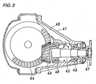
- Fig. 3 shows a differential gear device which is one example of apparatus in which a double row ball bearing of the present invention can be used.
- the differential gear includes a pinion shaft 42 rotatably supported on a housing 41 and having a pinion gear 43 provided at a rear end thereof, a ring gear 44 meshing with the pinion gear 43, a pair of inner and outer double row ball bearings 45 and 46 rotatably supporting the pinion shaft 42 on the housing 41 , and a drive shaft-connecting flange coupling 47 formed at an outer end of the pinion shaft 42.
- lubricating oil splashed up in accordance with the rotation of the ring gear 44 flows through a lubricating oil passageway 48 within the housing 41, and is introduced into a region between the pair of double row ball bearings 45 and 46.
- one 45 of the double row ball bearings is located on a side of the pinion gear 43, while the other 46 of the double row ball bearings is located on a side opposite to the pinion gear 43.
- the double row ball bearings 45 and 46 used in the differential gear device are arranged such that their smaller-diameter sides are opposed to each other in an axial direction, and the lubricating oil is supplied from the smaller-diameter side of each bearing (that is, from the region between the pair of double row ball bearings 45 and 46) and is discharged from the larger-diameter side, utilizing this pumping action.
- This lubricating method is commonly used.
- a double row ball bearing comprising:
- the difference between the revolution period of the larger diameter-side balls and the revolution period of the smaller diameter-side balls can be made small, for example, by increasing the diameter of the larger diameter-side balls while the diameter and contact angle of the smaller diameter-side balls and the pitch circle diameters of the two rows of balls are kept the same as those of a conventional bearing. Additionally, it is preferred to decrease the contact angle of the larger diameter-side balls. This can also be achieved merely by making the contact angle of the larger diameter-side balls smaller than the contact angle of the smaller diameter-side balls while keeping the diameter of the larger diameter-side balls equal to the diameter of the smaller diameter-side balls.
- a differential slip (spin) at an area of contact between the ball and the raceway surface increases, and the revolution speed decreases.
- the revolution period can be adjusted.
- the diameter of the smaller diameter-side balls may be decreased (in which case the number of the balls increases), and also the contact angle of the smaller diameter-side balls may be increased.
- the difference in pitch circle diameter between the row of larger diameter-side balls and the row of smaller diameter-side balls may be slightly reduced.
- the contact angles are so determined that the relation, ( ⁇ - 10) ⁇ ⁇ ⁇ ⁇ , is established where ⁇ (°) represents the contact angle of the larger diameter-side ball, and ⁇ (°) represents the contact angle of the smaller diameter-side ball.
- ⁇ ( ⁇ - 5)
- an axial rigidity of the large diameter-side balls is generally equal to an axial rigidity of the small diameter-side balls, and the life of the large diameter-side balls used under a large axial load can be prevented from being shortened.
- the pitch circle diameter of the larger diameter-side balls is made larger than the pitch circle diameter of the smaller diameter-side balls, and the two revolution periods are made equal to each other.
- the difference between the revolution period of the larger diameter-side balls and the revolution period of the smaller diameter-side balls is small, and therefore the flow of the lubricating oil in the bearing can be rectified, thereby enabling the low-torque design.
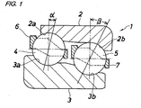
- Fig. 1 shows a first embodiment of a double row ball bearing of the present invention.
- This double row ball bearing 1 comprises an outer ring 2 which has two raceway surfaces 2a and 2b different in diameter from each other and is adapted to be mounted on a housing (not shown), an inner ring 3 which has two raceway surfaces 3a and 3b corresponding respectively to the raceway surfaces 2a and 2b of the outer ring 2 and is adapted to be mounted on a rotation shaft (not shown), a row of larger diameter-side balls 4 disposed between the raceway surface 2a of the outer ring 2 and the raceway surface 3a of the inner ring 3, a row of smaller diameter-side balls 5 which are disposed between the raceway surface 2b of the outer ring 2 and the raceway surface 3b of the inner ring 3 and have a pitch circle diameter smaller than a pitch circle diameter of the larger diameter-side balls 4, a larger-diameter cage 6 holding the row of larger diameter-side balls 4, and a smaller-diameter cage 7 holding the row of smaller
- an outer diameter of the right raceway surface 3b of the inner ring 3 is smaller than an outer diameter of the left raceway surface 3a of the inner ring 3, and an inner diameter of the right raceway surface 2b of the outer ring 2 is smaller than an inner diameter of the left raceway surface 2a of the outer ring 2.
- a contact angle of each larger diameter-side ball 4 and a contact angle of each smaller diameter side-ball 5 are generally in the same direction (These contact angles are not limited to the same angle.) .
- Each of the cages 6 and 7 is formed into a tapered shaped as a whole such that its diameter is increasing gradually from the right side toward the left side. Lubricating oil is supplied to the right side ( Fig. 1 ) (that is, the smaller-diameter side), and is discharged from the left side (in Fig. 1 ) (that is, the larger-diameter side) by a pumping action of the double row ball bearing 1.
- a pitch circle diameter of larger diameter-side balls is larger than a pitch circle diameter of smaller diameter-side balls
- a diameter and a contact angle of each larger diameter-side ball are equal respectively to a diameter and a contact angle of each smaller diameter-side ball
- a revolution period of the larger diameter-side balls is larger than a revolution period of the smaller diameter-side balls.
- the double row ball bearing 1 of this invention attention is directed to the difference between the two revolution periods, and the flow of the lubricating oil in the bearing 1 is rectified by lessening this difference to thereby enable the reduction of the running torque, and the contact angle of the larger diameter-side balls 4 is made smaller than the contact angle of the smaller diameter-side balls 5 without changing the pitch circle diameter so that the difference of the revolution period of the larger diameter-side balls 4 and the revolution period of the smaller diameter-side balls 5 can be made smaller as compared with the conventional bearing.
- Fig. 2 shows a second embodiment of a double row ball bearing of the invention.
- This second embodiment is identical to the first embodiment in that a contact angle of each larger diameter-side ball 8 is smaller than a contact angle of each smaller diameter-side ball 5, and differs from the first embodiment that a diameter of each larger diameter-side ball 8 is larger than a diameter of each smaller diameter-side ball 5 (that is, the diameter of the larger diameter-side ball 4 of the first embodiment as indicated in a dots-and-dash line in Fig. 2 ).
- the revolution period of the larger diameter-side balls 8 is further shortened, and the difference of the revolution period of the larger diameter-side ball 8 and the smaller diameter-side ball 5 is further lessened.
- Each of the double row ball bearings 1 shown in Figs. 1 and 2 can be suitably used as the bearings for rotatably supporting the pinion shaft 42 on the housing 41 in the differential gear of the automobile shown in Fig. 3 .
- the double row ball bearing 1 is lubricated by lubricating oil received within the housing 41. When a flow of the lubricating oil in the bearing 1 is disturbed, the running torque increases.
- the difference between the revolution period of the larger diameter-side balls 4, 8 and the revolution period of the smaller diameter-side balls 5 is smaller as compared with the conventional bearing, and therefore the disturbance of the flow of the lubricating oil is suppressed, thereby enabling the low-torque design.
- the double row ball bearings 1 of the invention can support the pinion shaft (rotation shaft) of the differential gear, and also can be used for supporting any other rotation shaft such for example as a pinion shaft of a transaxle apparatus.
Landscapes
- Engineering & Computer Science (AREA)
- General Engineering & Computer Science (AREA)
- Mechanical Engineering (AREA)
- Rolling Contact Bearings (AREA)
Abstract
Description
- This invention relates to a double row ball bearing, and more particularly to a double row ball bearing (called a tandem type) which can suitably support a pinion shaft, for example, of a final reduction gear of an automobile, and is lubricated by lubricating oil received within the final reduction gear.
- Tandem type double row ball bearings which include a plurality of balls arranged in two rows between an outer ring and an inner ring, and a cage holding these balls have been extensively used in a pinion shaft support apparatus for a vehicle, etc., as shown in
JP-A-2006-234100 -
Fig. 3 shows a differential gear device which is one example of apparatus in which a double row ball bearing of the present invention can be used. The differential gear includes apinion shaft 42 rotatably supported on ahousing 41 and having apinion gear 43 provided at a rear end thereof, aring gear 44 meshing with thepinion gear 43, a pair of inner and outer doublerow ball bearings pinion shaft 42 on thehousing 41 , and a drive shaft-connectingflange coupling 47 formed at an outer end of thepinion shaft 42. - In this differential gear, lubricating oil splashed up in accordance with the rotation of the
ring gear 44 flows through a lubricatingoil passageway 48 within thehousing 41, and is introduced into a region between the pair of doublerow ball bearings pinion shaft 43 and with respect.to an oil supply from theoil passageway 48, one 45 of the double row ball bearings is located on a side of thepinion gear 43, while the other 46 of the double row ball bearings is located on a side opposite to thepinion gear 43. When the doublerow ball bearings row ball bearings row ball bearings 45 and 46) and is discharged from the larger-diameter side, utilizing this pumping action. This lubricating method is commonly used. - In a pinion shaft support apparatus of a vehicle, etc., to reduce a running torque of a bearing in order to achieve a low-loss design has been a problem. For reducing the running torque, it is effective to suppress an oil agitation loss caused by the lubricating oil.
- It is an object of this invention to provide a double row ball bearing device in which a flow of lubricating oil in the bearing is rectified, thereby enabling a low-torque design.
- According to the present invention, there is provided a double row ball bearing comprising:
- an outer ring having a larger-diameter raceway surface and a smaller-diameter raceway;
- an inner ring having a larger-diameter raceway surface and a smaller-diameter raceway surface corresponding respectively to said larger-diameter and smaller-diameter raceway surfaces of said outer ring;
- a row of larger diameter-side balls disposed between said larger-diameter raceway surface of said outer ring and said larger-diameter raceway surface of said inner ring;
- a row of smaller diameter-side balls which are disposed between said smaller-diameter raceway surface of said outer ring and said smaller-diameter raceway surface of said inner ring and have a pitch circle diameter smaller than a pitch circle diameter of said larger diameter-side balls;
- a larger-diameter cage holding said row of larger diameter-side balls; and
- a smaller-diameter cage holding said row of smaller diameter-side balls,
- The difference between the revolution period of the larger diameter-side balls and the revolution period of the smaller diameter-side balls can be made small, for example, by increasing the diameter of the larger diameter-side balls while the diameter and contact angle of the smaller diameter-side balls and the pitch circle diameters of the two rows of balls are kept the same as those of a conventional bearing. Additionally, it is preferred to decrease the contact angle of the larger diameter-side balls. This can also be achieved merely by making the contact angle of the larger diameter-side balls smaller than the contact angle of the smaller diameter-side balls while keeping the diameter of the larger diameter-side balls equal to the diameter of the smaller diameter-side balls. When the contact angle is increased, a differential slip (spin) at an area of contact between the ball and the raceway surface increases, and the revolution speed decreases. Therefore, merely by changing the contact angle, the revolution period can be adjusted. Furthermore, the diameter of the smaller diameter-side balls may be decreased (in which case the number of the balls increases), and also the contact angle of the smaller diameter-side balls may be increased. Furthermore, the difference in pitch circle diameter between the row of larger diameter-side balls and the row of smaller diameter-side balls may be slightly reduced.
- Preferably, the contact angles are so determined that the relation, (β - 10) ≤ α < β, is established where α(°) represents the contact angle of the larger diameter-side ball, and β(°) represents the contact angle of the smaller diameter-side ball. When α = (β - 5) is established, an axial rigidity of the large diameter-side balls is generally equal to an axial rigidity of the small diameter-side balls, and the life of the large diameter-side balls used under a large axial load can be prevented from being shortened. For preventing the shortened life of the large diameter-side balls used in such a large axial load, it is also effective to make a curvature of the larger-diameter.raceway larger than a curvature of the smaller-diameter raceway.
- In case the difference in revolution period between the larger diameter side and the smaller diameter-side is large, a flow of lubricating oil at the larger-diameter side and a flow of lubricating oil at the smaller-diameter side interfere with each other within the bearing, so that the flow becomes complicated, thereby increasing a bearing torque. By synchronizing the two revolution periods with each other, the flow of the lubricating oil in the bearing can be rectified, so that the running torque of the bearing can be reduced.
- More preferably, in order to secure the flow of the lubricating oil from the smaller-diameter side to the larger-diameter side, the pitch circle diameter of the larger diameter-side balls is made larger than the pitch circle diameter of the smaller diameter-side balls, and the two revolution periods are made equal to each other. By doing so, the flow of the lubricating oil in the bearing can be optimized so as to reduce the running torque, and besides the two cages used respectively at the larger-diameter side and the smaller-diameter side can be replaced by a single cage, and therefore the number of the component parts can be reduced.
- In the double row ball bearing of the present invention, the difference between the revolution period of the larger diameter-side balls and the revolution period of the smaller diameter-side balls is small, and therefore the flow of the lubricating oil in the bearing can be rectified, thereby enabling the low-torque design.
-
-
Fig. 1 is a longitudinal cross-sectional view showing an upper portion of a first embodiment of a double row ball bearing of the present invention. -
Fig. 2 is a longitudinal cross-sectional view showing an upper portion of a second embodiment of a double row ball bearing of the invention. -
Fig. 3 is a longitudinal cross-sectional view of a differential gear which is one example of apparatus in which the double row ball bearings of the invention can be used. - Preferred embodiments of the present invention will now be described with reference to the drawings.
-
Fig. 1 shows a first embodiment of a double row ball bearing of the present invention. This double row ball bearing 1 comprises anouter ring 2 which has tworaceway surfaces inner ring 3 which has tworaceway surfaces raceway surfaces outer ring 2 and is adapted to be mounted on a rotation shaft (not shown), a row of larger diameter-side balls 4 disposed between theraceway surface 2a of theouter ring 2 and theraceway surface 3a of theinner ring 3, a row of smaller diameter-side balls 5 which are disposed between theraceway surface 2b of theouter ring 2 and theraceway surface 3b of theinner ring 3 and have a pitch circle diameter smaller than a pitch circle diameter of the larger diameter-side balls 4, a larger-diameter cage 6 holding the row of larger diameter-side balls 4, and a smaller-diameter cage 7 holding the row of smaller diameter-side balls 5. - In
Fig. 1 , an outer diameter of theright raceway surface 3b of theinner ring 3 is smaller than an outer diameter of theleft raceway surface 3a of theinner ring 3, and an inner diameter of theright raceway surface 2b of theouter ring 2 is smaller than an inner diameter of theleft raceway surface 2a of theouter ring 2. A contact angle of each larger diameter-side ball 4 and a contact angle of each smaller diameter side-ball 5 are generally in the same direction (These contact angles are not limited to the same angle.) . Each of thecages Fig. 1 ) (that is, the smaller-diameter side), and is discharged from the left side (inFig. 1 ) (that is, the larger-diameter side) by a pumping action of the double row ball bearing 1. - In a conventional double row ball bearing called a tandem type in which a pitch circle diameter of larger diameter-side balls is larger than a pitch circle diameter of smaller diameter-side balls, a diameter and a contact angle of each larger diameter-side ball are equal respectively to a diameter and a contact angle of each smaller diameter-side ball, and a revolution period of the larger diameter-side balls is larger than a revolution period of the smaller diameter-side balls. When the difference in revolution period between the larger-diameter side and the smaller-diameter side is large, a flow of lubricating oil at the larger-diameter side and a flow of lubricating oil at the smaller-diameter side interfere with each other, so that the flow becomes complicated, thereby increasing a bearing torque.
- In the double row ball bearing 1 of this invention, attention is directed to the difference between the two revolution periods, and the flow of the lubricating oil in the
bearing 1 is rectified by lessening this difference to thereby enable the reduction of the running torque, and the contact angle of the larger diameter-side balls 4 is made smaller than the contact angle of the smaller diameter-side balls 5 without changing the pitch circle diameter so that the difference of the revolution period of the larger diameter-side balls 4 and the revolution period of the smaller diameter-side balls 5 can be made smaller as compared with the conventional bearing. At the smaller-diameter side where the contact angle is relatively large, a differential slip (spin) at an area of contact between each smaller diameter-side ball 5 and the raceway surface increases, and the revolution speed decreases, and therefore the revolution period of the smaller diameter-side balls 5 becomes large, and becomes close to the revolution period of the larger diameter-side balls 4. Incidentally, the contact angles are so determined that the following relation is established: - (β - 10) ≤ α < β where α(°) represents the contact angle of the larger diameter-
side balls 4, and β(°) represents the contact angle of the smaller diameter-side balls 5. -
Fig. 2 shows a second embodiment of a double row ball bearing of the invention. This second embodiment is identical to the first embodiment in that a contact angle of each larger diameter-side ball 8 is smaller than a contact angle of each smaller diameter-side ball 5, and differs from the first embodiment that a diameter of each larger diameter-side ball 8 is larger than a diameter of each smaller diameter-side ball 5 (that is, the diameter of the larger diameter-side ball 4 of the first embodiment as indicated in a dots-and-dash line inFig. 2 ). In the second embodiment, the revolution period of the larger diameter-side balls 8 is further shortened, and the difference of the revolution period of the larger diameter-side ball 8 and the smaller diameter-side ball 5 is further lessened. - Each of the double
row ball bearings 1 shown inFigs. 1 and2 can be suitably used as the bearings for rotatably supporting thepinion shaft 42 on thehousing 41 in the differential gear of the automobile shown inFig. 3 . The double row ball bearing 1 is lubricated by lubricating oil received within thehousing 41. When a flow of the lubricating oil in thebearing 1 is disturbed, the running torque increases. However, in the doublerow ball bearings 1 of the invention, the difference between the revolution period of the larger diameter-side balls side balls 5 is smaller as compared with the conventional bearing, and therefore the disturbance of the flow of the lubricating oil is suppressed, thereby enabling the low-torque design. - The double
row ball bearings 1 of the invention can support the pinion shaft (rotation shaft) of the differential gear, and also can be used for supporting any other rotation shaft such for example as a pinion shaft of a transaxle apparatus.
Claims (4)
- A double row ball bearing comprising:an outer ring having a larger-diameter raceway surface and a smaller-diameter raceway;an inner ring having a larger-diameter raceway surface and a smaller-diameter raceway surface corresponding respectively to said larger-diameter and smaller-diameter raceway surfaces of said outer ring;a row of larger diameter-side balls disposed between said larger-diameter raceway surface of said outer ring and said larger-diameter raceway surface of said inner ring;a row of smaller diameter-side balls which are disposed between said smaller-diameter raceway surface of said outer ring and said smaller-diameter raceway surface of said inner ring and have a pitch circle diameter smaller than a pitch circle diameter of said larger diameter-side balls;a larger-diameter cage holding said row of larger diameter-side balls; anda smaller-diameter cage holding said row of smaller diameter-side balls,wherein a difference between a revolution period of said larger diameter-side balls and a revolution period of said smaller diameter-side balls is smaller than a difference between the revolution period of the larger diameter-side balls and the revolution period of the smaller diameter-side balls which would be obtained if the larger diameter-side ball and the smaller-diameter side ball are equal in diameter and contact angle to each other.
- A double row ball bearing according to claim 1, wherein the relation, (β - 10) ≤ α < β, is established, where α(°) represents the contact angle of said larger diameter-side ball, and β(°) represents the contact angle of said smaller diameter-side ball.
- A double row ball bearing according to claim 2, wherein the diameter of said larger diameter-side ball is larger than the diameter of said smaller-diameter side ball.
- A differential gear device comprising:a housing;a pinion shaft rotatably supported on the housing and having a pinion gear provided at a rear end thereof;a ring gear meshing with the pinion gear; anda pair of double row ball bearings rotatably supporting the pinion shaft on the housing, one of said pair of double row ball bearings being located on a side of the pinion gear and the other of said pair of double row bearings being located on a side opposite to the pinion gear,wherein at least one of said pair of double row ball bearings is provided with a double row ball bearing according to claim 1.
Applications Claiming Priority (1)
| Application Number | Priority Date | Filing Date | Title |
|---|---|---|---|
| JP2007078308A JP2008240769A (en) | 2007-03-26 | 2007-03-26 | Double row ball bearing |
Publications (2)
| Publication Number | Publication Date |
|---|---|
| EP1975427A2 true EP1975427A2 (en) | 2008-10-01 |
| EP1975427A3 EP1975427A3 (en) | 2011-12-21 |
Family
ID=39540502
Family Applications (1)
| Application Number | Title | Priority Date | Filing Date |
|---|---|---|---|
| EP08005682A Withdrawn EP1975427A3 (en) | 2007-03-26 | 2008-03-26 | Double row ball bearing and differential gear device |
Country Status (3)
| Country | Link |
|---|---|
| US (1) | US7909515B2 (en) |
| EP (1) | EP1975427A3 (en) |
| JP (1) | JP2008240769A (en) |
Families Citing this family (7)
| Publication number | Priority date | Publication date | Assignee | Title |
|---|---|---|---|---|
| DE102009057192A1 (en) * | 2009-12-05 | 2011-06-09 | Schaeffler Technologies Gmbh & Co. Kg | Multi-row ball bearing assembly |
| JP5720262B2 (en) * | 2011-01-20 | 2015-05-20 | 株式会社ジェイテクト | Rolling bearing device for wheels |
| JP5966851B2 (en) * | 2012-10-23 | 2016-08-10 | 日本精工株式会社 | Wheel support hub unit |
| US9453530B2 (en) * | 2014-06-12 | 2016-09-27 | Thinkom Solutions, Inc. | Compact integrated perimeter thrust bearing |
| EP3001051A1 (en) * | 2014-09-29 | 2016-03-30 | Aktiebolaget SKF | Bearing unit for pinions |
| DE102018107875A1 (en) * | 2018-04-04 | 2019-10-10 | Schaeffler Technologies AG & Co. KG | Tandem angular contact ball bearings |
| US11378121B2 (en) | 2019-12-10 | 2022-07-05 | Allison Transmission, Inc. | Multi-ball thrust bearing arrangement |
Citations (2)
| Publication number | Priority date | Publication date | Assignee | Title |
|---|---|---|---|---|
| JP2006234100A (en) | 2005-02-25 | 2006-09-07 | Jtekt Corp | Double-row angular contact ball bearing and vehicle pinion shaft support device |
| EP1724478A1 (en) | 2004-03-11 | 2006-11-22 | JTEKT Corporation | Skew contact double row ball bearing and bearing device for supporting pinion shaft |
Family Cites Families (8)
| Publication number | Priority date | Publication date | Assignee | Title |
|---|---|---|---|---|
| US1645345A (en) * | 1926-12-09 | 1927-10-11 | Okner Bernard | Ball bearing |
| FR2825765B1 (en) * | 2001-06-06 | 2003-09-26 | Eurocopter France | BALL BEARING WITH TWO DISSYMMETRIC ROWS OF BALLS WITH ANGULAR CONTACT, AND MOUNTING OF OVERHEAD SPROCKETS ON SUCH A BEARING |
| JP2003294032A (en) * | 2002-04-03 | 2003-10-15 | Koyo Seiko Co Ltd | Double-row rolling bearing and assembling method therefor |
| DE10239742B4 (en) * | 2002-05-10 | 2011-07-28 | Schaeffler Technologies GmbH & Co. KG, 91074 | Single-sided double angular contact ball bearings |
| DE10331936B4 (en) * | 2003-07-15 | 2017-01-26 | Schaeffler Technologies AG & Co. KG | Wheel bearing unit in angular ball bearing design |
| JP2005147331A (en) * | 2003-11-18 | 2005-06-09 | Ntn Corp | Double row rolling bearing |
| JP2005308177A (en) * | 2004-04-26 | 2005-11-04 | Koyo Seiko Co Ltd | Bearing device for supporting pinion shaft, and differential gear device |
| JP4722822B2 (en) * | 2006-12-05 | 2011-07-13 | Ntn株式会社 | Tandem type double row angular contact ball bearing |
-
2007
- 2007-03-26 JP JP2007078308A patent/JP2008240769A/en active Pending
-
2008
- 2008-03-25 US US12/076,937 patent/US7909515B2/en not_active Expired - Fee Related
- 2008-03-26 EP EP08005682A patent/EP1975427A3/en not_active Withdrawn
Patent Citations (2)
| Publication number | Priority date | Publication date | Assignee | Title |
|---|---|---|---|---|
| EP1724478A1 (en) | 2004-03-11 | 2006-11-22 | JTEKT Corporation | Skew contact double row ball bearing and bearing device for supporting pinion shaft |
| JP2006234100A (en) | 2005-02-25 | 2006-09-07 | Jtekt Corp | Double-row angular contact ball bearing and vehicle pinion shaft support device |
Also Published As
| Publication number | Publication date |
|---|---|
| US7909515B2 (en) | 2011-03-22 |
| EP1975427A3 (en) | 2011-12-21 |
| US20080240639A1 (en) | 2008-10-02 |
| JP2008240769A (en) | 2008-10-09 |
Similar Documents
| Publication | Publication Date | Title |
|---|---|---|
| US20070110352A1 (en) | Tapered roller bearing | |
| EP2503168B1 (en) | Rotation support device for pinion shaft | |
| US7909515B2 (en) | Double row ball bearing and differential gear device | |
| JP4285017B2 (en) | Differential equipment | |
| EP1840391B1 (en) | Rolling bearing device with a double row rolling contact bearing for supporting a pinion shaft | |
| US9593718B2 (en) | Multipoint contact ball bearing | |
| EP2003351A1 (en) | Double-row rolling bearing for supporting pinion shaft, and rolling bearing device with the same | |
| EP2749782A1 (en) | Liquid-lubricated bearing and vehicle pinion shaft support device | |
| US7934871B2 (en) | Double row ball bearing | |
| EP3073138A1 (en) | Cylindrical roller bearing and bearing device for transmission | |
| EP2816247A1 (en) | Tapered roller bearing and power transmission device using tapered roller bearing | |
| US20070196037A1 (en) | Skew contact double row ball bearing and bearing device for supporting pinion shaft | |
| US8794843B2 (en) | Rotation support device for pinion shaft | |
| EP3051160A1 (en) | Deep groove ball bearing | |
| CN105209772B (en) | Bearing units and bearings for bevel gear shafts | |
| JP2009036348A (en) | Tandem type double-row angular contact ball bearing and bearing device for pinion shaft | |
| US11215272B2 (en) | Transmission unit, in particular an axle drive or transfer case, having a transmission element mounted therein via at least one double-row angular contact ball bearing | |
| JPH07317884A (en) | Rotational support device for planetary gears | |
| US20090028486A1 (en) | Tapered roller bearing | |
| JP2007092860A (en) | Double-row angular contact ball bearing and vehicle pinion shaft support device | |
| JP5600926B2 (en) | Tandem type double row angular contact ball bearing | |
| US11703081B2 (en) | Rolling bearing | |
| JP2004232844A (en) | Double row ball bearing | |
| JP5007585B2 (en) | Double row ball bearing | |
| JP5050582B2 (en) | Bearing device for rotating shaft support |
Legal Events
| Date | Code | Title | Description |
|---|---|---|---|
| PUAI | Public reference made under article 153(3) epc to a published international application that has entered the european phase |
Free format text: ORIGINAL CODE: 0009012 |
|
| AK | Designated contracting states |
Kind code of ref document: A2 Designated state(s): AT BE BG CH CY CZ DE DK EE ES FI FR GB GR HR HU IE IS IT LI LT LU LV MC MT NL NO PL PT RO SE SI SK TR |
|
| AX | Request for extension of the european patent |
Extension state: AL BA MK RS |
|
| PUAL | Search report despatched |
Free format text: ORIGINAL CODE: 0009013 |
|
| RIC1 | Information provided on ipc code assigned before grant |
Ipc: F16C 19/56 20060101ALI20111110BHEP Ipc: F16C 19/18 20060101AFI20111110BHEP |
|
| AK | Designated contracting states |
Kind code of ref document: A3 Designated state(s): AT BE BG CH CY CZ DE DK EE ES FI FR GB GR HR HU IE IS IT LI LT LU LV MC MT NL NO PL PT RO SE SI SK TR |
|
| AX | Request for extension of the european patent |
Extension state: AL BA MK RS |
|
| 17P | Request for examination filed |
Effective date: 20120619 |
|
| AKX | Designation fees paid |
Designated state(s): DE |
|
| 17Q | First examination report despatched |
Effective date: 20130816 |
|
| STAA | Information on the status of an ep patent application or granted ep patent |
Free format text: STATUS: THE APPLICATION IS DEEMED TO BE WITHDRAWN |
|
| 18D | Application deemed to be withdrawn |
Effective date: 20170427 |