EP1975003B1 - Interior trim component and method of manufacturing the same - Google Patents
Interior trim component and method of manufacturing the same Download PDFInfo
- Publication number
- EP1975003B1 EP1975003B1 EP08006001.5A EP08006001A EP1975003B1 EP 1975003 B1 EP1975003 B1 EP 1975003B1 EP 08006001 A EP08006001 A EP 08006001A EP 1975003 B1 EP1975003 B1 EP 1975003B1
- Authority
- EP
- European Patent Office
- Prior art keywords
- end portion
- body portion
- interior trim
- trim component
- inboard
- Prior art date
- Legal status (The legal status is an assumption and is not a legal conclusion. Google has not performed a legal analysis and makes no representation as to the accuracy of the status listed.)
- Ceased
Links
- 238000004519 manufacturing process Methods 0.000 title claims description 4
- 238000000034 method Methods 0.000 claims description 10
- 239000000853 adhesive Substances 0.000 claims description 8
- 230000001070 adhesive effect Effects 0.000 claims description 8
- 238000009963 fulling Methods 0.000 claims description 5
- 239000000463 material Substances 0.000 claims description 5
- 239000000758 substrate Substances 0.000 claims description 3
- 239000010985 leather Substances 0.000 description 4
- 239000004744 fabric Substances 0.000 description 3
- 238000004513 sizing Methods 0.000 description 1
- 238000009966 trimming Methods 0.000 description 1
Images
Classifications
-
- B—PERFORMING OPERATIONS; TRANSPORTING
- B60—VEHICLES IN GENERAL
- B60R—VEHICLES, VEHICLE FITTINGS, OR VEHICLE PARTS, NOT OTHERWISE PROVIDED FOR
- B60R13/00—Elements for body-finishing, identifying, or decorating; Arrangements or adaptations for advertising purposes
- B60R13/02—Internal Trim mouldings ; Internal Ledges; Wall liners for passenger compartments; Roof liners
- B60R13/0237—Side or rear panels
- B60R13/0243—Doors
-
- B—PERFORMING OPERATIONS; TRANSPORTING
- B60—VEHICLES IN GENERAL
- B60R—VEHICLES, VEHICLE FITTINGS, OR VEHICLE PARTS, NOT OTHERWISE PROVIDED FOR
- B60R13/00—Elements for body-finishing, identifying, or decorating; Arrangements or adaptations for advertising purposes
- B60R13/02—Internal Trim mouldings ; Internal Ledges; Wall liners for passenger compartments; Roof liners
- B60R2013/0281—Internal Trim mouldings ; Internal Ledges; Wall liners for passenger compartments; Roof liners made of a plurality of visible parts
-
- Y—GENERAL TAGGING OF NEW TECHNOLOGICAL DEVELOPMENTS; GENERAL TAGGING OF CROSS-SECTIONAL TECHNOLOGIES SPANNING OVER SEVERAL SECTIONS OF THE IPC; TECHNICAL SUBJECTS COVERED BY FORMER USPC CROSS-REFERENCE ART COLLECTIONS [XRACs] AND DIGESTS
- Y10—TECHNICAL SUBJECTS COVERED BY FORMER USPC
- Y10T—TECHNICAL SUBJECTS COVERED BY FORMER US CLASSIFICATION
- Y10T29/00—Metal working
- Y10T29/49—Method of mechanical manufacture
- Y10T29/49826—Assembling or joining
Definitions
- an interior trim component provides a rigid and/or soft, aesthetically-pleasing surface that trims structure of a vehicle, such as, for example, door structure, roof structure, instrument panel structure, A-pillars, B-pillars, C-pillars, or the like.
- Document JP 5 092743 A shows an interior trim component corresponding to the preamble of claim 1.
- An interior trim component according to the invention is defined by the features of claim 1 and a method for manufacturing an interior trim component according to the invention is defined by the features of claim 10.
- an interior trim component is shown generally at 10 according to an embodiment.
- the interior trim component 10 is defined to include a vehicular door geometry such that the interior trim component 10 functions as a panel for trimming vehicular door structure (not shown).
- the interior trim component includes a vehicular door geometry, it will be appreciated that the interior trim component 10 is not limited to a particular geometry; as such, the interior trim component 10 may include a geometry that trims vehicular roof structure, instrument panel structure, pillar structure, or the like.
- the interior trim component 10 is further defined to include a first portion, which is shown generally at 12, and a second portion, which is shown generally at 14. Because the interior trim component 10 is formed to include a vehicular door geometry, the first portion 12 may be referred to as a body portion and the second portion 14 may be referred to as a bolster portion.
- the interior trim component 10 When joined to door structure, the interior trim component 10 defines an A-surface 16 that faces and is exposed to a passenger compartment area of a vehicle and a B-surface 18 that faces the door structure.
- the body portion 12 is defined to include a first A-surface portion 20 defined by a first color
- the bolster portion 14 is defined to include a second A-surface portion 22 defined by a second color that is different from the first color.
- an "A-surface” is a term of art that describes a surface that generally faces the passenger compartment of a vehicle, and, as such, may be alternatively referred to as an "inboard surface.”
- a "B-surface” is a term of art that describes a surface that generally faces away from the passage compartment of a vehicle, and, as such, may be referred to as an "outboard surface.”
- the disclosure includes the terms A- / inboard surface and B- / outboard surface, it will be appreciated that the above terms are used in reference to an embodiment of the invention and therefore do not limited the invention to a particular embodiment. The terms used to describe the invention should be given the broadest meaning by one of ordinary skill in the art.
- the first and second A-surface portions 20, 22 may be further defined to include an A-surface texture/grain characteristic.
- the A-surface portion 20 of the body portion 12 may be defined to include, for example, a first A-surface texture/grain
- the A-surface portion 22 of the bolster portion 14 may be defined to include, for example, a second A. surface texture/grain that is different from the first A-surface texture/grain.
- the first A-surface texture/grain may be defined by a relatively smooth A-surface texture/grain
- the second A-surface texture/grain may be defined by a leather or fabric A-surface texture/grain.
- above-described A-surface texture/grains are not limited to a smooth, leather, or fabric texture/grain and that any desirable A-surface texture/grain pattern may define the first and second A-surface portion 20, 22 of the interior trim component 10.
- the body portion 12 may be defined by a three-dimensional, substantially rigid substrate material defining the vehicle door geometry.
- the bolster portion 14 includes a thickness, T ( Figure 3B ), to define a three-dimensional geometry, the bolster portion is generally defined to include a two-dimensional unit of material that is applied over the body portion 12. Once the bolster portion 14 is applied over the body portion 12, the bolster portion 14 defines a decorative, aesthetically-pleasing A-surface portion 22.
- the bolster portion 14 may define a fabric, leather, or faux leather unit of material.
- an adhesive may be sprayed onto a rear, B-surface 24 of the bolster portion 14.
- the adhesive is applied over the entire B-surface 24 except as shown at 26a and 26b.
- the adhesive may be applied over the A-surface portion 20 of the body portion 12 corresponding to the positioning of the bolster portion 14; if the adhesive is applied to the A-surface portion 20 of the body portion 12, the adhesive is not applied to the corresponding A-surface portion 20 where portions 26a, 26b of the bolster portion 14 contact or is otherwise placed proximate the body portion 12.
- the first B-surface end portion 26a may define a first end portion of the bolster portion 14, which is shown generally at 28a.
- the second B-surface end portion 26b may define a second end portion of the bolster portion 14, which is shown generally at 28b.
- the first end portion 28a includes a geometry that may be correspondingly-received within a U-shape valley or groove 30 formed in A-surface portion 20 of the body portion 12. According to an embodiment, the first end portion 28a is tucked into the U-shape valley or groove 30 in a tucking operation or process. According to an embodiment, the tucking operation or process may be defined by a well-known tucking technique that is commonly referred to in the art as "Kime Komi.”
- the body portion 12 may includes one or more projections 34 that substantially perpendicularly extend away from the A-surface portion 20 and the B-surface 18.
- the projections 34 may assist in the securing of the second end portion 28b.
- the bolster portion 14 is defined to include a length and width such that when the second end portion 28b is tucked into the opening or passage 32, an end surface 36 ( Figure 3B ) of the second end portion 28b may be substantially flat or flush with the B-surface 18 defined by the body portion 12. Accordingly, although the second end portion 28b may be defined by a projection 38 that extends past the B-surface 18 defined by the body portion 12, the control over the length and width sizing of the bolster portion 14 may reduce scrap material of the bolster portion 14 such that the occurrence and existence of projections 38 are minimized when the second end portion 28b is tucked into opening or passage 32.
- bolster portion 14 is attached to the body portion 12 as described above, additional processing steps may be carried out.
- one or more of the bolster portion 14 and body portion 12 may be punched to define a door handle bezel opening 40 ( Figure 1 ) or the like.
Landscapes
- Engineering & Computer Science (AREA)
- Mechanical Engineering (AREA)
- Vehicle Interior And Exterior Ornaments, Soundproofing, And Insulation (AREA)
Description
- This application claims the benefit of
U.S. Provisional Patent Application No. 60/908,990 filed on March 30, 2007 - It is known in the art that vehicles, such as, for example, automotive vehicles, include interior trim components. Typically, an interior trim component provides a rigid and/or soft, aesthetically-pleasing surface that trims structure of a vehicle, such as, for example, door structure, roof structure, instrument panel structure, A-pillars, B-pillars, C-pillars, or the like.
- Document
JP 5 092743 A - The disclosure will now be described, by way of example, with reference to the accompanying drawings, in which:
-
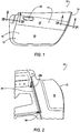
Figure 1 is a perspective view of the interior trim component in accordance with an examplary embodiment of the invention; -
Figure 2 is a partial perspective view of the interior trim component ofFigure 1 in accordance with an exemplary embodiment of the invention; -
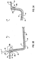
Figure 3A is a cross-sectional view of the interior trim component ofFigure 1 in accordance with an exemplary embodiment of the invention; and -
Figure 3B is a cross-sectional view of the interior trim component ofFigure 1 in accordance with an exemplary embodiment of the invention. - The Figures illustrate an exemplary embodiment of an interior trim component and method of manufacturing the same in accordance with an embodiment of the invention. It is to be generally understood that the nomenclature used herein is simply for convenience and the terms used to describe the invention should be given the broadest meaning by one of ordinary skill in the art.
- Referring to
Figures 1-3B , an interior trim component is shown generally at 10 according to an embodiment. The interior trim component 10 is defined to include a vehicular door geometry such that the interior trim component 10 functions as a panel for trimming vehicular door structure (not shown). Although the interior trim component includes a vehicular door geometry, it will be appreciated that the interior trim component 10 is not limited to a particular geometry; as such, the interior trim component 10 may include a geometry that trims vehicular roof structure, instrument panel structure, pillar structure, or the like. - The interior trim component 10 is further defined to include a first portion, which is shown generally at 12, and a second portion, which is shown generally at 14. Because the interior trim component 10 is formed to include a vehicular door geometry, the
first portion 12 may be referred to as a body portion and thesecond portion 14 may be referred to as a bolster portion. - When joined to door structure, the interior trim component 10 defines an
A-surface 16 that faces and is exposed to a passenger compartment area of a vehicle and a B-surface 18 that faces the door structure. If desired, thebody portion 12 is defined to include afirst A-surface portion 20 defined by a first color, and thebolster portion 14 is defined to include asecond A-surface portion 22 defined by a second color that is different from the first color. - It will be appreciated that an "A-surface" is a term of art that describes a surface that generally faces the passenger compartment of a vehicle, and, as such, may be alternatively referred to as an "inboard surface." Further, it will be appreciated that a "B-surface" is a term of art that describes a surface that generally faces away from the passage compartment of a vehicle, and, as such, may be referred to as an "outboard surface." Although the disclosure includes the terms A- / inboard surface and B- / outboard surface, it will be appreciated that the above terms are used in reference to an embodiment of the invention and therefore do not limited the invention to a particular embodiment. The terms used to describe the invention should be given the broadest meaning by one of ordinary skill in the art.
- The first and
second A-surface portions A-surface portion 20 of thebody portion 12 may be defined to include, for example, a first A-surface texture/grain, and theA-surface portion 22 of thebolster portion 14 may be defined to include, for example, a second A. surface texture/grain that is different from the first A-surface texture/grain. - According to an embodiment, the first A-surface texture/grain may be defined by a relatively smooth A-surface texture/grain, and the second A-surface texture/grain may be defined by a leather or fabric A-surface texture/grain. It will be appreciated that above-described A-surface texture/grains are not limited to a smooth, leather, or fabric texture/grain and that any desirable A-surface texture/grain pattern may define the first and
second A-surface portion - In general, the
body portion 12 may be defined by a three-dimensional, substantially rigid substrate material defining the vehicle door geometry. Although thebolster portion 14 includes a thickness, T (Figure 3B ), to define a three-dimensional geometry, the bolster portion is generally defined to include a two-dimensional unit of material that is applied over thebody portion 12. Once thebolster portion 14 is applied over thebody portion 12, thebolster portion 14 defines a decorative, aesthetically-pleasing A-surface portion 22. According to an embodiment, thebolster portion 14 may define a fabric, leather, or faux leather unit of material. - Referring to
Figures 3A and 3B , prior to applying thebolster portion 14 to thebody portion 12. an adhesive may be sprayed onto a rear, B-surface 24 of thebolster portion 14. According to an embodiment, the adhesive is applied over the entire B-surface 24 except as shown at 26a and 26b. However, it will be appreciated that the adhesive may be applied over theA-surface portion 20 of thebody portion 12 corresponding to the positioning of thebolster portion 14; if the adhesive is applied to theA-surface portion 20 of thebody portion 12, the adhesive is not applied to thecorresponding A-surface portion 20 whereportions bolster portion 14 contact or is otherwise placed proximate thebody portion 12. - The first B-
surface end portion 26a may define a first end portion of thebolster portion 14, which is shown generally at 28a. The second B-surface end portion 26b may define a second end portion of thebolster portion 14, which is shown generally at 28b. - According to an embodiment, the
first end portion 28a includes a geometry that may be correspondingly-received within a U-shape valley orgroove 30 formed inA-surface portion 20 of thebody portion 12. According to an embodiment, thefirst end portion 28a is tucked into the U-shape valley or groove 30 in a tucking operation or process. According to an embodiment, the tucking operation or process may be defined by a well-known tucking technique that is commonly referred to in the art as "KimeKomi." - Referring to
Figure 3B , once thefirst end portion 28a is tucked into the U-shape valley orgroove 30, the B-surface 24 including the adhesive is joined to theA-surface portion 20 of thebody portion 12. Then, thesecond end portion 28b that does not include the adhesive is tucked through a corresponding opening orpassage 32 defined by thebody portion 12. - As seen in
Figures 2 and3B , thebody portion 12 may includes one ormore projections 34 that substantially perpendicularly extend away from theA-surface portion 20 and the B-surface 18. When thesecond end portion 28b is tucked through the opening orpassage 32, theprojections 34 may assist in the securing of thesecond end portion 28b. - According to an embodiment, the
bolster portion 14 is defined to include a length and width such that when thesecond end portion 28b is tucked into the opening orpassage 32, an end surface 36 (Figure 3B ) of thesecond end portion 28b may be substantially flat or flush with the B-surface 18 defined by thebody portion 12. Accordingly, although thesecond end portion 28b may be defined by aprojection 38 that extends past the B-surface 18 defined by thebody portion 12, the control over the length and width sizing of thebolster portion 14 may reduce scrap material of thebolster portion 14 such that the occurrence and existence ofprojections 38 are minimized when thesecond end portion 28b is tucked into opening orpassage 32. - Once the
bolster portion 14 is attached to thebody portion 12 as described above, additional processing steps may be carried out. For example, one or more of thebolster portion 14 andbody portion 12 may be punched to define a door handle bezel opening 40 (Figure 1 ) or the like. - The present invention has been described with reference to certain exemplary embodiments thereof. However, it will be readily apparent to those skilled in the art that it is possible to embody the invention in specific forms other than those of the exemplary embodiments described above. The exemplary embodiments are merely illustrative and should not be considered restrictive in any way. The scope of the invention is defined by the appended claims and their equivalents, rather than by the preceding description.
Claims (15)
- An interior trim component, comprising: a body portion (12) defining an inboard-surface, and an outboard surface, wherein in the joined state of the interior trim component to door structure, said inboard-surface faces and is exposed to a passenger compartment area of a vehicle and said outboard surface faces the door structure, said body portion (12) being defined by a three-dimensional, substantially rigid substrate, wherein the body portion (12) is further defined by a groove (30) formed in the inboard-surface, and a passage (32) extending through the body portion (12) from the inboard-surface to the outboard-surface; and a bolster portion (14) including a first end portion (28a), and a second end portion (28b), wherein the first end portion (28a) is disposed in the groove (30) formed in the inboard-surface, wherein the second end portion (28b) is disposed in the passage and wherein said passage is further defined by projections (34) of body portion (12) that assist in securing of the second end portion (28b), characterized in that the projections (34) of body portion (12) substantially perpendicularly extend away from the inboard-surface and the outboard surface.
- The interior trim component according to claim 1, wherein the second end portion (28b) is further defined by an end surface.
- The interior trim component according to claim 2, wherein the end surface of the bolster portion (14) is substantially flush with the outboard-surface of the body portion (12).
- The interior trim component according to claim 2, wherein the end surface of the bolster portion (14) extends through the passage and past the outboard-surface of the body portion (12).
- The interior trim component according to claim 2, wherein the end surface of the bolster portion (14) extends into the passage and terminates prior to the outboard-surface of the body portion (12).
- The interior trim component according to claim 1, wherein the bolster portion is further defined to include a rear surface, wherein the rear surface is further defined by a first end portion (28a), a second end portion (28b), and an intermediate portion between the first and second end portion (28b), wherein an adhesive is disposed exclusively on the intermediate portion.
- The interior trim component according to claim 1, wherein the groove (30) formed in the inboard-surface of the body portion (12) includes a substantially U-shape groove (30) defining a valley.
- The interior trim component according to claim 1, wherein the groove (30) defines means for securing the first end portion (28a) of the bolster portion (14).
- The interior trim component according to claim 1, wherein the passage defines means for securing the second end portion (28b) of the bolster portion (14).
- A method for manufacturing an interior trim component (10), comprising the steps of: providing a body portion (12) defined by an inboard-surface, and an outboard-surface, wherein in the joined state of the interior trim component to door structure, said inboard-surface faces and is exposed to a passenger compartment area of a vehicle and said outboard surface faces the door structure, wherein the body portion (12) is further defined by a groove (30) formed in the inboard-surface, and a passage extending through the body portion (12) from the inboard-surface to the outboard-surface; providing a bolster portion (14) including a first end portion (28a), and a second end portion (28b); securing the first end portion (28a) of the bolster portion (14) in the groove (30) formed in the inboard-surface; and securing the second end portion (28b) of the bolster portion (14) in the passage, wherein the body portion (12) is defined by a three-dimensional, substantially rigid substrate material wherein said passage is further defined by projections (34) of body portion (12) that assist in securing of the second end portion (28b), characterized in that the projections (34) of body portion (12) substantially perpendicularly extend away from the inboard-surface and the outboard surface.
- The method according to claim 10, wherein the securing the first end portion (28a) step further comprises the step of tucking the first end portion (28a) in the groove (30) formed in the inboard-surface, wherein the securing the second end portion (28b) step further comprises the step of tucking the second end portion (28b) in the passage.
- The method according to claim 10, wherein the second end portion (28b) is further defined by an end surface.
- The method according to claim 12, wherein the securing the second end portion (28b) step is further defined by the step of locating the end surface of the bolster portion (14) substantially flush with the outboard-surface of the body portion (12).
- The method according to claim 12, wherein the securing the second end portion (28b) step is further defined by the step of locating the end surface of the bolster portion (14) through the passage and past the outboard-surface of the body portion (12).
- The method according to claim 12, wherein the securing the second end portion (28b) step is further defined by the step of locating the end surface of the bolster portion (14) within the passage but prior to the outboard-surface of the body portion (12).
Applications Claiming Priority (1)
| Application Number | Priority Date | Filing Date | Title |
|---|---|---|---|
| US90899007P | 2007-03-30 | 2007-03-30 |
Publications (3)
| Publication Number | Publication Date |
|---|---|
| EP1975003A2 EP1975003A2 (en) | 2008-10-01 |
| EP1975003A3 EP1975003A3 (en) | 2012-07-04 |
| EP1975003B1 true EP1975003B1 (en) | 2016-03-23 |
Family
ID=39619417
Family Applications (1)
| Application Number | Title | Priority Date | Filing Date |
|---|---|---|---|
| EP08006001.5A Ceased EP1975003B1 (en) | 2007-03-30 | 2008-03-28 | Interior trim component and method of manufacturing the same |
Country Status (2)
| Country | Link |
|---|---|
| US (1) | US8020922B2 (en) |
| EP (1) | EP1975003B1 (en) |
Family Cites Families (10)
| Publication number | Priority date | Publication date | Assignee | Title |
|---|---|---|---|---|
| JPH0353928Y2 (en) * | 1985-03-26 | 1991-11-27 | ||
| JPH0228018A (en) * | 1988-07-18 | 1990-01-30 | Toyota Motor Corp | Method for processing end of surface leather material |
| US5111619A (en) * | 1991-08-12 | 1992-05-12 | General Motors Corporation | Door trim panel retaining assembly |
| JPH0592743A (en) * | 1991-10-03 | 1993-04-16 | Toyota Motor Corp | Mounting construction of cloth-like body for inner facing member of vehicle |
| US5529370A (en) * | 1995-08-04 | 1996-06-25 | Ford Motor Company | Trim panel mounting assembly |
| JP3835061B2 (en) * | 1999-06-04 | 2006-10-18 | トヨタ紡織株式会社 | Car door trim |
| US7051438B2 (en) * | 2001-03-22 | 2006-05-30 | Intier Automotive Inc. | Method for manufacturing a vehicular door assembly |
| US7073843B2 (en) * | 2004-04-06 | 2006-07-11 | Lear Corporation | Trim panel assembly and method of manufacture |
| US7240955B2 (en) * | 2005-05-19 | 2007-07-10 | Faurecia Interior Systems | Methods and apparatus for connecting door trim to a door module |
| US20080238063A1 (en) * | 2007-03-30 | 2008-10-02 | Vanderpool Vaughn D | Trim Panel and Method of Manufacturing the Same |
-
2008
- 2008-03-28 US US12/057,579 patent/US8020922B2/en not_active Expired - Fee Related
- 2008-03-28 EP EP08006001.5A patent/EP1975003B1/en not_active Ceased
Also Published As
| Publication number | Publication date |
|---|---|
| EP1975003A2 (en) | 2008-10-01 |
| US8020922B2 (en) | 2011-09-20 |
| EP1975003A3 (en) | 2012-07-04 |
| US20090200819A1 (en) | 2009-08-13 |
Similar Documents
| Publication | Publication Date | Title |
|---|---|---|
| US6248200B1 (en) | Method of making a trim panel assembly including integral arm rest portion | |
| EP2188152B1 (en) | Vehicle panel | |
| US7810836B2 (en) | Invisible airbag cover having a tear line | |
| US8764891B1 (en) | Headliner edge treatment | |
| US7686386B2 (en) | Automotive body and trim assembly with complementary locating and positioning features and method of assembling same | |
| US5941590A (en) | Trim panel with 180 degree periphery edge wrap | |
| CA2672235A1 (en) | Multi-finish deep draw mold behind film | |
| US12383929B2 (en) | Vehicle structure | |
| US20080237925A1 (en) | Vehicle Component and Method For Making a Vehicle Component | |
| US8020922B2 (en) | Interior trim component and method of manufacturing the same | |
| CN104002757A (en) | Weakening of leather skins | |
| US10870393B1 (en) | Headliner for a vehicle | |
| JP6632094B2 (en) | Automotive interior parts | |
| US20050168015A1 (en) | Headliner with integrally-molded energy distribution zone | |
| EP2195181B1 (en) | Visor made from a vehicle panel material | |
| JP2008513293A (en) | Trim with decorative surface | |
| US20140262005A1 (en) | Method and apparatus for partially laminating a component, in particular a motor vehicle component | |
| US20130221698A1 (en) | Negative thermoforming process for vehicle interior coverings | |
| US20050140168A1 (en) | Door trim panel assembly having integrated soft-touch aesthetic feature and method of manufacturing same | |
| US20050225113A1 (en) | Decorative covering for an interior trim component | |
| US20070132212A1 (en) | Headliner System | |
| US20080115364A1 (en) | Headliner with Weakened Area and Method of Making Same | |
| US11104286B2 (en) | Energy absorption member for vehicle trim | |
| US20230365076A1 (en) | Cladding Part and Method for Producing a Cladding Part | |
| US20060157881A1 (en) | Method of pre-applying a bolster assembly to an interior trim part |
Legal Events
| Date | Code | Title | Description |
|---|---|---|---|
| PUAI | Public reference made under article 153(3) epc to a published international application that has entered the european phase |
Free format text: ORIGINAL CODE: 0009012 |
|
| AK | Designated contracting states |
Kind code of ref document: A2 Designated state(s): AT BE BG CH CY CZ DE DK EE ES FI FR GB GR HR HU IE IS IT LI LT LU LV MC MT NL NO PL PT RO SE SI SK TR |
|
| AX | Request for extension of the european patent |
Extension state: AL BA MK RS |
|
| RIC1 | Information provided on ipc code assigned before grant |
Ipc: B60R 13/02 20060101AFI20120306BHEP |
|
| PUAL | Search report despatched |
Free format text: ORIGINAL CODE: 0009013 |
|
| AK | Designated contracting states |
Kind code of ref document: A3 Designated state(s): AT BE BG CH CY CZ DE DK EE ES FI FR GB GR HR HU IE IS IT LI LT LU LV MC MT NL NO PL PT RO SE SI SK TR |
|
| AX | Request for extension of the european patent |
Extension state: AL BA MK RS |
|
| RIC1 | Information provided on ipc code assigned before grant |
Ipc: B60R 13/02 20060101AFI20120530BHEP |
|
| 17P | Request for examination filed |
Effective date: 20121227 |
|
| AKX | Designation fees paid |
Designated state(s): DE FR GB |
|
| 17Q | First examination report despatched |
Effective date: 20130301 |
|
| GRAP | Despatch of communication of intention to grant a patent |
Free format text: ORIGINAL CODE: EPIDOSNIGR1 |
|
| INTG | Intention to grant announced |
Effective date: 20150807 |
|
| GRAS | Grant fee paid |
Free format text: ORIGINAL CODE: EPIDOSNIGR3 |
|
| GRAA | (expected) grant |
Free format text: ORIGINAL CODE: 0009210 |
|
| RAP1 | Party data changed (applicant data changed or rights of an application transferred) |
Owner name: GRUPO ANTOLIN-IRAUSA, S.A. |
|
| AK | Designated contracting states |
Kind code of ref document: B1 Designated state(s): DE FR GB |
|
| REG | Reference to a national code |
Ref country code: GB Ref legal event code: FG4D |
|
| REG | Reference to a national code |
Ref country code: FR Ref legal event code: PLFP Year of fee payment: 9 |
|
| REG | Reference to a national code |
Ref country code: DE Ref legal event code: R096 Ref document number: 602008042990 Country of ref document: DE |
|
| REG | Reference to a national code |
Ref country code: DE Ref legal event code: R097 Ref document number: 602008042990 Country of ref document: DE |
|
| PLBE | No opposition filed within time limit |
Free format text: ORIGINAL CODE: 0009261 |
|
| STAA | Information on the status of an ep patent application or granted ep patent |
Free format text: STATUS: NO OPPOSITION FILED WITHIN TIME LIMIT |
|
| REG | Reference to a national code |
Ref country code: FR Ref legal event code: PLFP Year of fee payment: 10 |
|
| 26N | No opposition filed |
Effective date: 20170102 |
|
| PGFP | Annual fee paid to national office [announced via postgrant information from national office to epo] |
Ref country code: FR Payment date: 20170220 Year of fee payment: 10 |
|
| PGFP | Annual fee paid to national office [announced via postgrant information from national office to epo] |
Ref country code: GB Payment date: 20170306 Year of fee payment: 10 |
|
| PGFP | Annual fee paid to national office [announced via postgrant information from national office to epo] |
Ref country code: DE Payment date: 20170329 Year of fee payment: 10 |
|
| REG | Reference to a national code |
Ref country code: DE Ref legal event code: R119 Ref document number: 602008042990 Country of ref document: DE |
|
| GBPC | Gb: european patent ceased through non-payment of renewal fee |
Effective date: 20180328 |
|
| PG25 | Lapsed in a contracting state [announced via postgrant information from national office to epo] |
Ref country code: DE Free format text: LAPSE BECAUSE OF NON-PAYMENT OF DUE FEES Effective date: 20181002 |
|
| PG25 | Lapsed in a contracting state [announced via postgrant information from national office to epo] |
Ref country code: GB Free format text: LAPSE BECAUSE OF NON-PAYMENT OF DUE FEES Effective date: 20180328 |
|
| PG25 | Lapsed in a contracting state [announced via postgrant information from national office to epo] |
Ref country code: FR Free format text: LAPSE BECAUSE OF NON-PAYMENT OF DUE FEES Effective date: 20180331 |