EP1974821A1 - Method and apparatus for transporting magnetic or magnetisable microbeads - Google Patents
Method and apparatus for transporting magnetic or magnetisable microbeads Download PDFInfo
- Publication number
- EP1974821A1 EP1974821A1 EP07006148A EP07006148A EP1974821A1 EP 1974821 A1 EP1974821 A1 EP 1974821A1 EP 07006148 A EP07006148 A EP 07006148A EP 07006148 A EP07006148 A EP 07006148A EP 1974821 A1 EP1974821 A1 EP 1974821A1
- Authority
- EP
- European Patent Office
- Prior art keywords
- poles
- electromagnets
- capillary tube
- row
- magnetic
- Prior art date
- Legal status (The legal status is an assumption and is not a legal conclusion. Google has not performed a legal analysis and makes no representation as to the accuracy of the status listed.)
- Withdrawn
Links
Images









Classifications
-
- B—PERFORMING OPERATIONS; TRANSPORTING
- B03—SEPARATION OF SOLID MATERIALS USING LIQUIDS OR USING PNEUMATIC TABLES OR JIGS; MAGNETIC OR ELECTROSTATIC SEPARATION OF SOLID MATERIALS FROM SOLID MATERIALS OR FLUIDS; SEPARATION BY HIGH-VOLTAGE ELECTRIC FIELDS
- B03C—MAGNETIC OR ELECTROSTATIC SEPARATION OF SOLID MATERIALS FROM SOLID MATERIALS OR FLUIDS; SEPARATION BY HIGH-VOLTAGE ELECTRIC FIELDS
- B03C1/00—Magnetic separation
- B03C1/02—Magnetic separation acting directly on the substance being separated
- B03C1/23—Magnetic separation acting directly on the substance being separated with material carried by oscillating fields; with material carried by travelling fields, e.g. generated by stationary magnetic coils; Eddy-current separators, e.g. sliding ramp
- B03C1/24—Magnetic separation acting directly on the substance being separated with material carried by oscillating fields; with material carried by travelling fields, e.g. generated by stationary magnetic coils; Eddy-current separators, e.g. sliding ramp with material carried by travelling fields
- B03C1/253—Magnetic separation acting directly on the substance being separated with material carried by oscillating fields; with material carried by travelling fields, e.g. generated by stationary magnetic coils; Eddy-current separators, e.g. sliding ramp with material carried by travelling fields obtained by a linear motor
-
- B—PERFORMING OPERATIONS; TRANSPORTING
- B03—SEPARATION OF SOLID MATERIALS USING LIQUIDS OR USING PNEUMATIC TABLES OR JIGS; MAGNETIC OR ELECTROSTATIC SEPARATION OF SOLID MATERIALS FROM SOLID MATERIALS OR FLUIDS; SEPARATION BY HIGH-VOLTAGE ELECTRIC FIELDS
- B03C—MAGNETIC OR ELECTROSTATIC SEPARATION OF SOLID MATERIALS FROM SOLID MATERIALS OR FLUIDS; SEPARATION BY HIGH-VOLTAGE ELECTRIC FIELDS
- B03C1/00—Magnetic separation
- B03C1/02—Magnetic separation acting directly on the substance being separated
- B03C1/025—High gradient magnetic separators
- B03C1/031—Component parts; Auxiliary operations
- B03C1/033—Component parts; Auxiliary operations characterised by the magnetic circuit
- B03C1/0335—Component parts; Auxiliary operations characterised by the magnetic circuit using coils
-
- B—PERFORMING OPERATIONS; TRANSPORTING
- B03—SEPARATION OF SOLID MATERIALS USING LIQUIDS OR USING PNEUMATIC TABLES OR JIGS; MAGNETIC OR ELECTROSTATIC SEPARATION OF SOLID MATERIALS FROM SOLID MATERIALS OR FLUIDS; SEPARATION BY HIGH-VOLTAGE ELECTRIC FIELDS
- B03C—MAGNETIC OR ELECTROSTATIC SEPARATION OF SOLID MATERIALS FROM SOLID MATERIALS OR FLUIDS; SEPARATION BY HIGH-VOLTAGE ELECTRIC FIELDS
- B03C1/00—Magnetic separation
- B03C1/02—Magnetic separation acting directly on the substance being separated
- B03C1/28—Magnetic plugs and dipsticks
- B03C1/288—Magnetic plugs and dipsticks disposed at the outer circumference of a recipient
-
- B—PERFORMING OPERATIONS; TRANSPORTING
- B03—SEPARATION OF SOLID MATERIALS USING LIQUIDS OR USING PNEUMATIC TABLES OR JIGS; MAGNETIC OR ELECTROSTATIC SEPARATION OF SOLID MATERIALS FROM SOLID MATERIALS OR FLUIDS; SEPARATION BY HIGH-VOLTAGE ELECTRIC FIELDS
- B03C—MAGNETIC OR ELECTROSTATIC SEPARATION OF SOLID MATERIALS FROM SOLID MATERIALS OR FLUIDS; SEPARATION BY HIGH-VOLTAGE ELECTRIC FIELDS
- B03C2201/00—Details of magnetic or electrostatic separation
- B03C2201/18—Magnetic separation whereby the particles are suspended in a liquid
Definitions
- the invention concerns a method for transporting magnetic or magnetisable microbeads immersed in a liquid contained in a capillary tube having a length symmetry axis which defines an axial direction, said transporting being effected in the absence of a static magnetic field in said capillary tube.
- the invention further concerns an apparatus for transporting magnetic or magnetisable microbeads immersed in a liquid contained in a capillary tube.
- Magnetic particles e.g. magnetic beads, of a size of several micrometers in diameter are used in biomedical analysis.
- probe molecules immobilized on the surface of magnetic microbeads are used for performing a method in which probe molecules specifically interact with complimentary target molecules.
- a method uses for e.g. DNA probes immobilized on the surface of magnetic microbeads for recognition of and hybridization with complimentary target DNA in a solution.
- microbeads carrying the DNA probes are brought into a solution containing particles which carry on them target.DNA for possible homologous pairing and subsequent identification of the target DNA.
- the amount of target molecules within a certain volume of solution is determined using electro-optical or electrochemical measurements.
- the advantage of using magnetic particles in a method of the above mentioned kind is that magnetic particles can be manipulated using magnetic fields independently from any flow pattern of the solution, e.g. for the extraction of target-specific magnetic particles from the solution where the interaction of magnetic particles carrying the probes interact with the target molecules.
- magnetic particles can be manipulated using magnetic fields independently from any flow pattern of the solution, e.g. for the extraction of target-specific magnetic particles from the solution where the interaction of magnetic particles carrying the probes interact with the target molecules.
- transport of magnetic particles means that the magnetic particles are effectively moved, that is displaced along a transport path by a magnetic force, and not just retained by a magnetic force at a given place and thereby separated from a liquid solution which flows close to a magnet.
- Manipulation of magnetic particles in general, and in particular transport of magnetic particles is a difficult task, because the magnetic particles used are usually superparamagnetic microbeads which have a rather weak effective relative magnetic susceptibility ⁇ eff (typically ⁇ eff ⁇ 1, due to demagnetization effects of the mostly spherical particles) and because the volume of a magnetic particle is small.
- a very small microbead has thus no effective magnetization when there is no external magnetic field applied to it, i.e. it is superparamagnetic.
- Junho Joung et al. IEEE Transactions on Magnetics, Vol. 36, No. 4, July 2000, pages 2012-2014 , describes an arrangement for displacing clusters of magnetic particles.
- This arrangement comprises an array of uniformly spaced electromagnetic posts, wherein each post has one electromagnet pole the end of which faces one side of a straight pipe which contains a solution in which magnetic particles are immersed.
- the poles of the electromagnetic posts are positioned close to, on opposite sides the pipe and are uniformly spaced in an axial direction defined by the length symmetry axis of the pipe.
- the first pole is located on a first side of the pipe
- the second pole is located on a second side of the pipe opposite to the first side thereof, and further from the first end of the pipe than the first pole
- the third pole is located on the first side of the pipe and further from the first end of the pipe than the second pole
- the fourth pole is located on the second side of the pipe and further from the first end of the pipe than the third pole, and so on.
- the electromagnetic post are activated one after the other and one at a time by a simple driving circuit which turns them on and off in sequence starting from the electromagnetic post whose pole is the one nearest to the first end of the pipe.
- a first aim of the invention is to provide a method and an apparatus of the above mentioned kind which do not require the use of large magnets or electromagnets which have to be mechanically moved.
- aims are achieved by means of a method defined by claim 1.
- Claims 2 to 5 define preferred embodiments of this method.
- the above aims are achieved by using an apparatus defined by claim 6 for transporting microbeads having a non-spherical shape.
- the above aims are achieved by using an apparatus defined by claim 6 for transporting microbeads having a spherical shape.
- Type 2 microbeads are of similar size as the microbeads of type 1, but differ from them by a non-spherical 'corn flake'-like shape. They are characterized by a product v b ⁇ b , which is estimated from transport experiments to be about a factor 30 higher than the corresponding product for the microbeads of type 1.
- a capillary tube 3 is used as chamber within which the transport of the magnetic microbeads takes place.
- the capillary tube is e.g. a glass capillary having an inner diameter of 0.58 millimeter and an outer diameter of 1 millimeter.
- a first embodiment of an apparatus according to the invention for transporting magnetic or magnetisable microbeads immersed in a liquid contained in a capillary tube is described hereinafter with reference to Figures 1a to 3 and 7 .
- Fig. 1a shows a first electromagnet 1.1 comprising a coil 10 wound around magnetic core 9 having poles 11 and 12.
- Fig. 1a shows this electromagnet in a first polarity state designated by 1.1+ and indicated by the sense of the excitation current applied to coil 10 and by the corresponding direction of the magnetic flux indicated by arrows in poles 11 and 12.
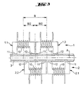
- electromagnet 1.1 belongs to a first row 1 of electromagnets which are arranged on a first side of a capillary tube 3 having a length axis A as represented in the arrangement shown by Fig. 3 .
- Fig. 1b shows the same first electromagnet 1.1 as in Fig. 1a , but when this electromagnet is in a second polarity state designated by 1.1- which is opposite to the first polarity state designated by 1.1+ and shown by Fig. 1a .
- Fig. 2a shows a second electromagnet 2.1 comprising a coil 10 wound around magnetic core 9 having poles 11 and 12.
- Fig. 2a shows this electromagnet in a first polarity state designated by 2.1+ and indicated by the sense of the excitation current applied to coil 10 and by the corresponding direction of the magnetic flux indicated by arrows in poles 11 and 12.
- electromagnet 2.1 belongs to a second row 2 of electromagnets which are arranged on a second side of the capillary tube 3, the second side being opposite to the first side thereof.
- Fig. 2b shows the same second electromagnet 2.1 as in Fig. 2a , but when this electromagnet is in a second polarity state designated by 2.1- which is opposite to the first polarity state designated by 2.1+ and shown by Fig. 2a .
- an apparatus comprises the following components: a capillary tube 3, a first row 1 of uniformly spaced electromagnets forming a first linear array of poles 11, 12 located on a first side of the capillary tube 3, a second row 2 of uniformly spaced electromagnets forming a second linear array of poles 11, 12 located on a second side of the capillary tube 3, the second side being opposite to the first side.
- Capillary tube 3 has a length symmetry axis A and is adapted for receiving a liquid containing an amount of magnetic or magnetisable microbeads to be transported.
- the first linear array of poles 11, 12 and the second linear array of poles 11, 12 extend in an axial direction defined by the length symmetry axis A of the capillary tube 3.
- Each of the electromagnets has an electromagnetic circuit which comprises a magnetic core 9 which has two poles 11, 12, which are neighboring poles in the first or the second linear array of poles, and a coil 10 coupled with that magnetic core 9.
- Magnetic core 9 is e.g. a ferrite core or any other suitable soft magnetic material. The dimensions of each magnetic core are in the millimeter-centimeter-range.
- At least two successive poles 11, 12 of the first array of poles are portions of a first one-piece magnetic core 9 and at least two successive poles 11, 12 of the second array of poles are portions of a second one-piece magnetic core 9.
- Each of poles 11, 12 has an outer end surface that faces capillary tube 3, and each of poles 11, 12 defines a magnetic axis which is perpendicular to the length symmetry axis A of the capillary tube 3.
- the magnetic axis of all poles lie in a common plane which passes through the length symmetry axis A of capillary tube 3.
- the poles 11, 12 of the first row 1 of electromagnets and the poles 11, 12 of the second row 2 of electromagnets are axially offset with respect to each other.
- Fig. 3 which shows that B is the center-to-center distance between neighbor electromagnets of the same row, and that the electromagnets of rows on opposite sides of capillary tube 3 are shifted of a distance B/2 with respect to each other.
- This feature is important for achieving the desired effect, i.e. the transport of the magnetic microbeads in the axial direction.
- Fig. 7 shows a schematic representation of an electrical circuit which is adapted for applying to the coils 10 of the electromagnetic circuits of the first row 1 of electromagnets, and to the coils 10 of the electromagnetic circuits of the second row 2 of electromagnets, periodical electrical current pulses of uniform duration.
- the electrical circuit represented therein comprises a DC current source 15, an AC current source 16 and switches 13 and 14 actuated by a control circuit 17.
- AC current source 16 optionally comprises a phase shifter which introduces a phase shift ⁇ .
- the electrical circuit just described has output terminals which are connected with the input terminals of the electromagnets of the first and the second row of electromagnets in such a way that periodical electrical current pulses delivered at the output terminals of the electrical circuit are applied to the coils 10 of the electromagnets in the order of their position in the axial direction. Under the control of control circuit 17, switches 13 and 14 change the polarity of the current pulses applied to the coils 10 of the electromagnets.
- Successive current pulses delivered at the output terminals of the electrical circuit shown by Fig. 7 extend over overlapping time intervals and the phase difference between successive pulses is constant and is comprised between 90 and 180 degrees.
- the electrical circuit of Fig. 7 provides direct current pulses or a superposition of direct current pulses and AC current pulses to the coils 10 of the electromagnets in the sequences described in detail hereinafter with reference to Figures 4a to 6 in the description of a first example of a method according to the invention.
- a first embodiment of a method according to the invention for transporting magnetic or magnetisable microbeads immersed in a liquid contained in a capillary tube is described hereinafter with reference to Figures 4a to 6 .
- the method according to this first embodiment is carried out e.g. with an apparatus of the type described above with reference to Figures 1a to 3 and 7 and comprises:
- step (c) the electrical current pulses of uniform duration are applied to the coils 10 in the order of the position of the corresponding electromagnets in the axial direction, successive pulses extend over overlapping time intervals, and the phase difference between successive pulses is constant and is comprised between 90 and 180 degrees.
- the application of the electrical current pulses to the coils 10 of the electromagnets generates a magnetic field within capillary tube 3. The amplitude, polarity and position of this magnetic field varying so with time that the magnetic field moves forward in the axial direction, and thereby causes transport of the microbeads in the axial direction.
- the magnetic microbeads introduced into capillary tube 3 comprise magnetic microbeads having a non-spherical shape.
- the magnetic microbeads introduced into capillary tube 3 comprise magnetic microbeads having a spherical shape.
- the electrical current pulses applied to the coils 10 have a frequency in the range of 0.1 to 5 cycles per second.
- an alternating current signal having a frequency in the range of 1 to 100 cycles per second is superposed onto said electrical current pulses.
- Figures 4a to 4g illustrate transport of microbeads along the capillary tube shown in Fig. 3 . This transport is achieved by successively actuating the electromagnet arrangements so that these are successively in the polarity states represented in Figures 4a to 4g .
- the polarity states of the electromagnets are indicated in the same way as in Figures 1a to 2b , that is by a + or a - sign on the right of the reference number which designates the electromagnet, e.g. 1.1+, 2.2-, etc.
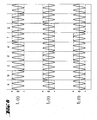
- Fig. 5 shows direct current intensities I 1 .(t), I 2 .(t), I 3 .(t) applied to the electromagnet arrangements represented in Figures 4a to 4g in order that these are successively in the polarity states shown by Figures 4a to 4g .
- the letters a , b , c , d , e , f and g designate time intervals.
- Fig. 5 shows three direct current intensities which have a phase difference of 120° with respect to each other.
- four direct current intensities which have a phase difference of 90° with respect to each other are applied to the electromagnets. This embodiment provides a more efficient transport.
- Fig. 4a show the polarity states of the electromagnets during time interval a in Fig. 5 .
- Figures 4b to 4g show the polarity states of the electromagnets during each of the time intervals b , c , d , e , f and g respectively.
- Fig. 4a shows a cluster 5 of distributed magnetic microbeads formed by the magnetic fields generated by the current intensities I 1 . (t), I 2 . (t), I 3 . (t) applied to the electromagnets during time interval a in Fig. 5 .
- Figures 4b to 4g show the position of the cluster 5 of distributed magnetic microbeads formed by the magnetic fields generated by the current intensities I 1 . (t), I 2 . (t), I 3 . (t) applied to the electromagnets during each of the time intervals b , c , d , e , f and g respectively.
- the cluster 5 of distributed magnetic microbeads shown in each of Figures 4a to 4g is composed of magnetic microbeads distributed over a the cross-section of the capillary tube 3 and over a short segment thereof.
- the cluster 5 of distributed magnetic microbeads has approximately the shape of a column or a disk.
- the cluster 5 is not a compact mass of magnetic microbeads, but a swarm of magnetic microbeads spaced from each other and moving as a group.
- the current intensities applied to the electromagnets are not the direct current pulses shown in Fig. 5 , but current pulses formed by multiplication of the current pulses shown in Fig. 5 with an alternating current signal.
- Fig. 6 shows current pulses I 1 . (t), I 2 . (t), I 3 . (t) which are the result of this multiplication.
- a second embodiment of an apparatus according to the invention for transporting magnetic or magnetisable microbeads immersed in a liquid contained in a capillary tube is described hereinafter with reference to Figures 8a to 10 , 14 and 15 to 23 .
- Fig. 8a shows a first electromagnet 1.1 comprising a planar coil 20 wound around a magnetic core element 19.
- Fig. 8a shows this electromagnet in a first polarity state designated by 1.1+ and indicated by the sense of the excitation current applied to planar coil 20 and by the corresponding direction of the magnetic flux indicated by arrows in pole 21.
- electromagnet 1.1 belongs to a first row 1 of electromagnets which are arranged on a first side of a capillary tube 3 having a length axis A as represented in the arrangement shown by Fig. 10 .
- Fig. 8b shows the same first electromagnet 1.1 as in Fig. 8a , but when this electromagnet is in a second polarity state designated by 1.1- which is opposite to the first polarity state designated by 1.1+ and shown by Fig. 8a .
- Fig. 9a shows a second electromagnet 2.1 comprising a planar coil 20 wound around a magnetic core element 19.
- Fig. 9a shows this electromagnet in a first polarity state designated by 2.1+ and indicated by the sense of the excitation current applied to planar coil 20 and by the corresponding direction of the magnetic flux indicated by arrows in pole 21.
- electromagnet 2.1 belongs to a second row 2 of electromagnets which are arranged on a second side of the capillary tube 3, the second side being opposite to the first side thereof.
- Fig. 9b shows the same second electromagnet 2.1 as in Fig. 9a , but when this electromagnet is in a second polarity state designated by 2.1- which is opposite to the first polarity state designated by 2.1+ and shown by Fig. 9a .
- an apparatus comprises the following components: a capillary tube 3, a first linear array of uniformly spaced poles 21 of a first row 1 of electromagnets located on a first side of the capillary tube 3, a second linear array of uniformly spaced poles 21 of a second row 2 of electromagnets located on a second side of the capillary tube 3, the second side being opposite to the first side.
- Capillary tube 3 has a length symmetry axis A and is adapted for receiving a liquid containing an amount of magnetic or magnetisable microbeads to be transported.
- the first linear array of poles 21 and the second linear array of poles 21 extend in an axial direction defined by the length symmetry axis A of the capillary tube 3.
- Each one of the electromagnets has an electromagnetic circuit which comprises a magnetic core element 19 and a planar coil 20 coupled therewith.
- At least two successive poles 21 of the first row 1 of electromagnets are portions of a first one-piece magnetic core 23, and at least two successive poles 21 of the second row 2 of electromagnets are portions of a second one-piece magnetic core 23.
- Each of poles 21 has an outer end surface that faces capillary tube 3, and each of poles 21 defines a magnetic axis which is perpendicular to the length symmetry axis A of the capillary tube 3.
- the magnetic axis of all poles lie in a common plane which passes through the length symmetry axis A of capillary tube 3.
- the poles 21 of the first row 1 of electromagnets and the poles 21 of the second row 2 of electromagnets are axially offset with respect to each other.
- Fig. 10 which shows that B is the center-to-center distance between neighbor poles of the same row, and that the poles of rows on opposite sides of capillary tube 3 are shifted of a distance B/2 with respect to each other.
- This feature is important for achieving the desired effect, i.e. the transport of the magnetic microbeads in the axial direction.
- all magnetic core elements 19 of the first row 1 of electromagnets are portions of a first one-piece magnetic core 23 and all magnetic core elements 19 of the second row 2 of electromagnets are portions of a second one-piece magnetic core 23.
- Magnetic core 23 is e.g. a ferrite core or any other suitable soft magnetic material. Magnetic core 23 can also be formed by assembling together a ferrite plate and a wafer on which pin-shaped poles have been formed, e.g. by the powder blasting process described hereinafter.
- each of the magnetic core elements 19 has the shape of a pin that terminates in a sharp pointed tip.
- the distance between the tip of a pole 21 of the first row of electromagnets and the next tip of a pole 21 of the second row of electromagnets is at most two times the width of the capillary tube 3.
- each of the electromagnets comprises a planar coil 20 which has a central opening and the pin shaped magnetic core element 19 is inserted through the opening of the planar coil.
- Fig. 14 shows a schematic representation of an embodiment of the above mentioned electrical circuit which is adapted for applying to the coils 20 of the electromagnetic circuits of the first row of electromagnets 1, and to the coils 20 of the electromagnetic circuits of the second row of electromagnets 2, periodical electrical current pulses of uniform duration.
- the electrical circuit represented therein comprises a DC current source 15, an AC current source 16 and switches 13 and 14 actuated by a control circuit 17.
- AC current source 16 optionally comprises a phase shifter which introduces a phase shift ⁇ .
- the electrical circuit just described has output terminals which are connected with the input terminals of the electromagnets of the first row 1 and the second row 2 of electromagnets in such a way that periodical electrical current pulses delivered at the output terminals of the electrical circuit are applied to the planar coils 20 of the electromagnets in the order of their position in the axial direction. Under the control of control circuit 17, switches 13 and 14 change the polarity of the current pulses applied to the planar coils 20 of the electromagnets.
- the electrical circuit of Fig. 14 provides direct current pulses or a superposition of direct current pulses and AC current pulses to the planar coils 20 of the electromagnets in the sequences described in detail hereinafter with reference to Figures 11a to 13 in the description of a second example of a method according to the invention.
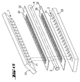
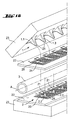
- Fig. 15 shows a perspective exploded view showing the components of an embodiment the apparatus shown by Fig. 10 .
- such an embodiment comprises an upper ferrite plate 23 in which a first row 1 of magnetic poles 21 has been formed, an upper printed circuit board 22 having a thickness of 100 micrometer on which a first row of planar coils 20 having each a thickness of 35 micrometer and a pitch of 200 micrometer has been formed, a capillary tube 3, a lower printed circuit board 22 on which a second row of planar coils 20 has been formed, and a lower ferrite plate 23 in which a second row 2 of magnetic poles 21 has been formed.
- the magnetic poles of each row belong to portions 19 (shown in Figures 8a to 9b ) of a ferrite plate 23.
- Portions 19 are magnetic core elements which have the shape of a pin that terminates in a sharp pointed pole tip 21.
- Fig. 16 shows an enlarged view of a portion of Fig. 15 .
- Fig. 16 shows the spatial correspondence between the location of the poles 21 and the location of the corresponding planar coils 20.
- each of the planar coils 20 has a central opening which is aligned with an opening of the printed circuit board and each of the poles 21 having the shape of a pin is inserted through the central opening of the corresponding planar coil 20 and the corresponding opening of the printed circuit board.
- Fig. 17 shows a longitudinal cross-sectional view of an apparatus comprising components of the type shown in Figures 15 and 16 , wherein the planar coils 20 are arranged on both sides of each printed circuit board 22 (the structure of such a planar coil is shown by Fig. 19 ) in order to generate stronger magnetic fields.
- capillary tube 3 contains 3 different liquids 4a, 4b and 4c which are e.g. different reagents.
- Fig. 17 shows a cluster 5 of distributed magnetic microbeads being transported along capillary tube 3 by actuation of the planar coils 20 as described below in a second example of a method according to the invention.
- Fig. 18 shows a cross-sectional view of the apparatus shown by Fig. 17 along plane XVIII- XVIII represented in Fig. 17 .
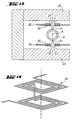
- Fig. 19 shows a perspective view of a planar coil arranged on both sides of a printed circuit board.
- Figures 20 to 23 illustrate various steps of the process used for forming of magnetic poles 21 on a ferrite wafer by powder blasting micro-erosion technology.
- Fig. 20 illustrates a first step of the process wherein a first mask 31 having rectilinear web 32 is positioned on a ferrite wafer 30a.
- the web 32 protects a linear region of the ferrite wafer 30a and after this run a rectilinear ridge 33 results in the wafer now designated as wafer 30b.
- Fig. 21 illustrates a second step of the fabrication of pole tips 21 on a ferrite wafer.
- a second mask 34 which has an array of webs parallel to each other and extending in a direction perpendicular to ridge 33, is positioned on ferrite wafer 30b. After powder blasting of wafer 30b with mask 34 on it, the ridge 33 is transformed into an array of ferrite posts or pins 36
- Fig. 22 shows a ferrite wafer 30c with pole tips fabricated according to the steps shown by Figures 20 and 21 .
- Fig. 23 shows an enlarged view of a cut-out XXIII in Fig. 22 .
- a second embodiment of a method according to the invention for transporting magnetic or magnetisable microbeads immersed in a liquid contained in a capillary tube is described hereinafter with reference to Figures 11a to 13 .
- the method according to this first embodiment is carried out e.g. with an apparatus of the type described above with reference to Figures 8a to 10 , 14 and 15 to 23 comprises:
- step (c) the electrical current pulses of uniform duration are applied to the coils 20 in the order of the position of the corresponding electromagnets in the axial direction, successive pulses extending over overlapping time intervals and the phase difference between successive pulses being constant and comprised between 90 and 180 degrees.
- the application of the electrical current pulses to the coils 20 of the electromagnets generates a magnetic field within capillary tube 3. The amplitude, polarity and position of this magnetic field varying so with time that the magnetic field moves forward in the axial direction, and thereby causes transport of the microbeads in the axial direction.
- the magnetic microbeads introduced into capillary tube 3 comprise magnetic microbeads having a non-spherical shape.
- the magnetic microbeads introduced into capillary tube 3 comprise magnetic microbeads having a spherical shape.
- the electrical current pulses applied to the coils 20 have a frequency in the range of 0.1 to 5 cycles per second. If the coils 20 are mounted on a printed circuit board with no particular cooling other than unforced air convection the maximum current density that can be applied to the coils is about 150 A/square millimeter and that corresponds to a maximum current intensity of about 0.5 A for the coils 20 of the type described above in the second example of an apparatus according to the invention.
- an alternating current signal having a frequency in the range of 1 to 100 cycles per second is superposed onto said electrical current pulses.
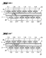
- Figures 11a to 11g illustrate transport of microbeads along the capillary tube shown in Fig. 10 . This transport is achieved by successively actuating the electromagnet arrangements so that these are successively in the polarity states represented in Figures 11a to 11g .
- the polarity states of the electromagnets are indicated in the same way as in Figures 8a to 9b , that is by a + or a - sign on the right of the reference number which designates the electromagnet, e.g. 1.1+, 2.2+, etc.
- Fig. 12 shows direct current intensities I 1 . (t), I 2 . (t), I 3 . (t), I 4 . (t) applied to the electromagnet arrangements represented in Figures 11a to 11g in order that these are successively in the polarity states shown by Figures 11a to 11g .
- the letters a , b , c , d , e , f , g and h designate time intervals.
- Figure 12 shows four direct current intensities which have a phase difference of 90° with respect to each other.
- Figure 11a show the polarity states of the electromagnets during time interval a in Figure 12 .
- Figures 11b to 11g show the polarity states of the electromagnets during each of the time intervals b , c , d , e , f , g and h respectively.
- Fig. 11a shows a cluster 5 of distributed magnetic microbeads formed by the magnetic fields generated by the current intensities I 1 . (t), I 2 . (t), I 3 . (t), I 4 . (t) applied to the electromagnets during time interval a in Figure 12 .
- Figures 11b to 11h show the position of the cluster 5 of distributed magnetic microbeads formed by the magnetic fields generated by the current intensities I 1 . (t), I 2 . (t), I 3 . (t), I 4 . (t) applied to the electromagnets during each of the time intervals b , c , d , e , f , g and h respectively.
- the cluster 5 of distributed magnetic microbeads shown in each of Figures 11a to 11g is composed of magnetic microbeads distributed over a the cross-section of the capillary tube 3 and over a short segment thereof.
- the cluster 5 of distributed magnetic microbeads has approximately the shape of a column or a disk.
- the cluster 5 is not a compact mass of magnetic microbeads, but a swarm of magnetic microbeads spaced from each other and moving as a group.
- the current intensities applied to the electromagnets are not the direct current pulses shown in Fig. 12 , but current pulses formed by multiplication of the current pulses shown in Fig. 12 with an alternating current signal.
- Fig. 13 shows current pulses I 1 . (t), I 2 . (t), I 3 . (t), I 4 . (t) which are the result of this multiplication.
- the magnetic fields generated by the electromagnets induce a dynamic vortex-like motion of the microbeads of the microbead cluster 5 over the entire cross-section of capillary tube 3 and this motion takes place during the transport of cluster 5 in axial direction.
- the vortex-like motion of the microbeads of the cluster 5 being transported in advantageous in applications where interaction of the microbeads with target particles is desirable.
Landscapes
- Physical Or Chemical Processes And Apparatus (AREA)
- Apparatus Associated With Microorganisms And Enzymes (AREA)
Abstract
Description
- The invention concerns a method for transporting magnetic or magnetisable microbeads immersed in a liquid contained in a capillary tube having a length symmetry axis which defines an axial direction, said transporting being effected in the absence of a static magnetic field in said capillary tube.
- The invention further concerns an apparatus for transporting magnetic or magnetisable microbeads immersed in a liquid contained in a capillary tube.
- Magnetic particles, e.g. magnetic beads, of a size of several micrometers in diameter are used in biomedical analysis.
- For example, probe molecules immobilized on the surface of magnetic microbeads are used for performing a method in which probe molecules specifically interact with complimentary target molecules. Such a method uses for e.g. DNA probes immobilized on the surface of magnetic microbeads for recognition of and hybridization with complimentary target DNA in a solution. In this method microbeads carrying the DNA probes are brought into a solution containing particles which carry on them target.DNA for possible homologous pairing and subsequent identification of the target DNA. Upon reaction with molecules to be probed, the amount of target molecules within a certain volume of solution is determined using electro-optical or electrochemical measurements.
- The advantage of using magnetic particles in a method of the above mentioned kind is that magnetic particles can be manipulated using magnetic fields independently from any flow pattern of the solution, e.g. for the extraction of target-specific magnetic particles from the solution where the interaction of magnetic particles carrying the probes interact with the target molecules. Thus, by manipulation of the magnetic particles with controlled magnetic fields an important relative motion of the magnetic particles with respect to the fluid and thereby with respect to the target molecules can be created, and this effect strongly increases the probability of capturing target molecules with the magnetic particles, i.e. the probability of binding target molecules to probe molecules fixed on the surfaces of the magnetic particles. Magnetic particles with captured molecules on them can then be extracted to place where detection or collection of the captured molecules takes place.
- In the context of the invention transport of magnetic particles means that the magnetic particles are effectively moved, that is displaced along a transport path by a magnetic force, and not just retained by a magnetic force at a given place and thereby separated from a liquid solution which flows close to a magnet.
- Manipulation of magnetic particles in general, and in particular transport of magnetic particles, is a difficult task, because the magnetic particles used are usually superparamagnetic microbeads which have a rather weak effective relative magnetic susceptibility χeff (typically χeff < 1, due to demagnetization effects of the mostly spherical particles) and because the volume of a magnetic particle is small. The magnetic moment induced in a microbead is given by µ=VχeffB 0/µ0 , with B0 the magnetic field generated by the permanent magnet, χeff the magnetic permeability and V the magnetic microbead volume. A very small microbead has thus no effective magnetization when there is no external magnetic field applied to it, i.e. it is superparamagnetic. The magnetic force on an induced moment in a magnetic induction field is given by

- From (1) it is apparent that to create a strong magnetic force on a magnetic particle it is necessary to have a large magnetic moment µ and a large gradient of the magnetic induction.
- For this reason relatively important magnetic fields of about 10-2 T and large magnetic field gradients from 10 to 100 T/m have to be generated locally, e.g. within a capillary tube used for the transport of a solution containing target molecules, in order to generate magnetic forces which are sufficiently strong for manipulating magnetic particles in a solution. Prior art solutions for the separation and sorting of magnetic microbeads exist, but most of them require use of large permanent magnets or electromagnets which are mechanically moved.
- Junho Joung et al., IEEE Transactions on Magnetics, Vol. 36, No. 4, July 2000, pages 2012-2014, describes an arrangement for displacing clusters of magnetic particles. This arrangement comprises an array of uniformly spaced electromagnetic posts, wherein each post has one electromagnet pole the end of which faces one side of a straight pipe which contains a solution in which magnetic particles are immersed. The poles of the electromagnetic posts are positioned close to, on opposite sides the pipe and are uniformly spaced in an axial direction defined by the length symmetry axis of the pipe. Starting from a first end of the pipe which is the inlet thereof, the first pole is located on a first side of the pipe, the second pole is located on a second side of the pipe opposite to the first side thereof, and further from the first end of the pipe than the first pole, the third pole is located on the first side of the pipe and further from the first end of the pipe than the second pole, the fourth pole is located on the second side of the pipe and further from the first end of the pipe than the third pole, and so on. In order to transport the magnetic particles along the pipe, the electromagnetic post are activated one after the other and one at a time by a simple driving circuit which turns them on and off in sequence starting from the electromagnetic post whose pole is the one nearest to the first end of the pipe. When an electromagnetic post of this arrangement is turned on, the pole thereof attracts magnetic particles which form a cluster on the portion of the inner side of the pipe wall which is close to that pole. When the electromagnetic posts are turned on and off in sequence as mentioned above, the magnetic forces successively exerted by the poles on the magnetic particles causes motion of a cluster of magnetic particles back and forth along a zigzag path between opposite side walls of the pipe. The motion of the cluster of magnetic particles in the axial direction defined by the length axis of the pipe is thus rather slow. The utility of this arrangement is thus limited to applications in which a very slow motion of the magnetic particles is acceptable. In the above mentioned zigzag movement the magnetic particles keep the form of a cluster and are thus not homogeneously distributed over the cross-section of the pipe. This is an important drawback, because it strongly reduces the probability of biological interactions of probes, e.g. DNA probes, fixed on the surface of the magnetic particles with target molecules carried by a liquid flowing through the pipe. A further limitation of the above mentioned arrangement described by Joung et al. is that the magnetic forces that can be created with such an arrangement are relatively weak and are effective only within a very limited spatial range. The utility of this arrangement is thus limited to applications in which pipes of very small diameter are used. Otherwise, the magnetic forces created by the arrangement would not be sufficiently strong to achieve a movement of the cluster of magnetic particles.
- A first aim of the invention is to provide a method and an apparatus of the above mentioned kind which do not require the use of large magnets or electromagnets which have to be mechanically moved.
- According to a first aspect of the invention the above aims are achieved by means of a method defined by
claim 1.Claims 2 to 5 define preferred embodiments of this method. - According to a second aspect of the invention the above aims are achieved by means of an apparatus defined by
claim 6.Claims 7 to 10 define preferred embodiments of this apparatus. - According to a third aspect of the invention the above aims are achieved by using an apparatus defined by
claim 6 for transporting microbeads having a non-spherical shape. - According to a fourth aspect of the invention the above aims are achieved by using an apparatus defined by
claim 6 for transporting microbeads having a spherical shape. - The main advantages obtained with a method and an apparatus according to the invention are as follows:
- use of large magnets or electromagnets which have to be mechanically moved is not required,
- the apparatus comprises a miniaturized and low-price electromagnetic arrangement made by using coils made on simple printed circuit boards and ferrite microstructures patterned from ferrite wafers using a batch-type powder blasting micro-erosion technology,
- the magnetic particles are displaced over several millimeters in a single attraction event between neighboring poles, and
- average transport velocities of about 1 millimeter per second are achievable,
- the magnetic particles can be displaced back and forth within one or more liquids contained in a capillary tube.
The efficient transport of magnetic microbeads achieved with instant invention is particularly useful in biochemical reactions wherein as many as possible interactions between magnetic microbeads which carry e.g. probe molecules (e.g. single stranded DNA) on their surface and which specifically interact with complementary target molecules (e.g. a complementary target DNA).
The small dimensions of an apparatus according to the invention make possible to build with it a compact bioanalysis system. - The subject invention will now be described in terms of its preferred embodiments with reference to the accompanying drawings. These embodiments are set forth to aid the understanding of the invention, but are not to be construed as limiting.
- The subject invention will now be described in terms of its preferred embodiments with reference to the accompanying drawings. These embodiments are set forth to aid the understanding of the invention, but are not to be construed as limiting.
-
Fig. 1a shows a first embodiment of a first electromagnet of a first row of electromagnets in a first polarity state. -
Fig. 1b shows the first electromagnet ofFig. 1a in a second polarity state. -
Fig. 2a shows a first embodiment of a first electromagnet of a second row of electromagnets in a first polarity state. -
Fig. 2b shows the first electromagnet ofFig. 2a in a second polarity state. -
Fig. 3 shows a cross-sectional view of a portion of a first embodiment of an apparatus according to the invention comprising a capillary tube located between a first row of electromagnets and a second row of electromagnets. -
Figures 4a to 4g illustrate transport of beads along the capillary tube shown inFig. 3 achieved by successively actuating the electromagnet arrangements so that these are successively in the states represented inFigures 4a to 4g . -
Fig. 5 shows direct current intensities applied to the electromagnet arrangements represented inFigures 4a to 4g in order that these are successively in the states shown byFigures 4a to 4g . -
Fig. 6 shows current pulses formed by multiplication of the current pulses shown inFigure 5 , with an alternating current signal. -
Fig. 7 a schematic representation of the circuit used for applying direct current voltages and alternating current voltages to the electromagnet arrangements shown inFigures 4a to 4g . -
Fig. 8a shows a second embodiment of a first electromagnet of a first row in a first polarity state. -
Fig. 8b shows the first electromagnet ofFig. 8a in a second polarity state. -
Fig. 9a shows a second embodiment of a first electromagnet of a second row in a first polarity state. -
Fig. 9b shows the first electromagnet ofFig. 9a in a second polarity state. -
Fig. 10 shows a cross-sectional view of a portion of a second embodiment of an apparatus according to the invention comprising a capillary tube located between a first row of electromagnets of the type shown inFig. 8a and a second row of electromagnets of the type shown inFig. 9a . -
Figures 11a to 11h illustrate transport of beads along the capillary tube shown inFig. 10 achieved by successively actuating the electromagnet arrangements so that these are successively in the states represented inFigures 11a to 11h . -
Fig. 12 shows direct current intensities applied to the electromagnet arrangements represented inFigures 11a to 11h in order that these are in the states shown byFigures 11a to 11h . -
Fig. 13 shows additional alternating current intensities applied to the electromagnet arrangements shown inFigures 11a to 11h . -
Fig. 14 shows a schematic representation of the circuit used for applying direct current voltages and alternating current voltages to the electromagnet arrangements shown inFigures 11a to 11h . -
Fig. 15 shows a perspective exploded view showing the components of an embodiment the apparatus shown byFig. 10 . -
Fig. 16 shows an enlarged view of a portion ofFig. 15 . -
Fig. 17 shows a cross-sectional view of an apparatus according toFigures 15 and16 . -
Fig. 18 shows a cross-sectional view along plane XVIII-XVIII represented inFig. 17 . -
Fig. 19 shows a perspective view of a coil arranged on both sides of a printed circuit board. -
Fig. 20 illustrates a first step of the fabrication of pole tips on a ferrite wafer. -
Fig. 21 illustrates a second step of the fabrication of pole tips on a ferrite wafer. -
Fig. 22 shows a ferrite wafer with pole tips fabricated according to the steps shown byFigures 20 and 21 . -
Fig. 23 shows an enlarged view of a cut-out XXIII inFig. 22 . -
- 1
- first row of electromagnets
- 1.1
- electromagnet
- 1.2
- electromagnet
- 1.3
- electromagnet
- 2
- second row of electromagnets
- 2.1
- electromagnet
- 2.2
- electromagnet
- 2.3
- electromagnet
- 2.4
- electromagnet
- 3
- capillary tube
- 4
- liquid
- 4a
- first liquid
- 4b
- second liquid
- 4c
- third liquid
- 5
- cluster of beads
- 9
- magnetic core
- 10
- coil
- 11
- pole
- 12
- pole
- 13
- polarity reversal switch
- 14
- polarity reversal switch
- 15
- direct-current source
- 16
- alternating current source
- 17
- control unit
- 19
- magnetic core element / portion of
magnetic core 23 - 20
- coil
- 21
- pole / pole tip
- 22
- printed circuit board
- 23
- magnetic core / ferrite plate
- 24
- bore hole
- 30a
- ferrite wafer
- 30b
- ferrite wafer
- 30c
- ferrite wafer
- 31
- mask
- 32
- web of
mask 31 - 33
- ridge
- 34
- mask
- 35
- web of
mask 34 - 36
- projection
- A
- symmetry axis of capillary tube
- B
- distance between electromagnets
- Preferred embodiments of the invention are described hereinafter with reference to the accompanying drawings.
- The operation of the apparatus and methods described hereinafter is based on the following principles:
- The magnetic force exerted in the direction X (e.g, along the length axis of the
capillary tube 3 in the examples described hereinafter) on a magnetic microbead in a magnetic field is given by:
- Where
- µ 0 is the permeability in vacuum
- vb is the volume of the microbead
- χ b the magnetic susceptibility of the microbead
- H is the vector of the external magnetic field.
- In addition to the magnetic force, the magnetic microbead in motion with a velocity vector v experiences a hydrodynamic drag force. If there is no macroscopic motion of the liquid solution containing the microbeads, the hydrodynamic viscous force acting on a spherical particle of radius Rb , is given by:

- Where
η is the viscosity of the fluid (for water, η = 8.9 x 10 -4 N s/m2). - When the microbead is subjected to a magnetic attraction force, it will accelerate till the force associated with viscosity equals the magnetic force. For example, to displace a magnetic particle having a radius Rb =0.5 µm with a velocity of 0.5 mm/s requires a magnetic force of about 4 pN. This equilibrium velocity in the x-direction can be found by equalizing eq. (1) with the x-axis projection of eq. (2), giving a stationary microbead velocity

- In the examples described below two types of magnetic microbeads are used:
-
Type 1 microbeads are spherical 10 micrometer size micromer®-M microbeads with a susceptibility χ b = 0.045, and a volume vb = 523 cubic micrometer purchased from Micromod Partikeltechnologie GmbH, Rostock, Germany. -
Type 2 microbeads are of similar size as the microbeads oftype 1, but differ from them by a non-spherical 'corn flake'-like shape. They are characterized by a product vb χ b, which is estimated from transport experiments to be about a factor 30 higher than the corresponding product for the microbeads oftype 1. - In the examples described below a
capillary tube 3 is used as chamber within which the transport of the magnetic microbeads takes place. The capillary tube is e.g. a glass capillary having an inner diameter of 0.58 millimeter and an outer diameter of 1 millimeter. - A first embodiment of an apparatus according to the invention for transporting magnetic or magnetisable microbeads immersed in a liquid contained in a capillary tube is described hereinafter with reference to
Figures 1a to 3 and7 . -
Fig. 1a shows a first electromagnet 1.1 comprising acoil 10 wound aroundmagnetic core 9 havingpoles Fig. 1a shows this electromagnet in a first polarity state designated by 1.1+ and indicated by the sense of the excitation current applied tocoil 10 and by the corresponding direction of the magnetic flux indicated by arrows inpoles Fig. 3 , electromagnet 1.1 belongs to afirst row 1 of electromagnets which are arranged on a first side of acapillary tube 3 having a length axis A as represented in the arrangement shown byFig. 3 . -
Fig. 1b shows the same first electromagnet 1.1 as inFig. 1a , but when this electromagnet is in a second polarity state designated by 1.1- which is opposite to the first polarity state designated by 1.1+ and shown byFig. 1a . -
Fig. 2a shows a second electromagnet 2.1 comprising acoil 10 wound aroundmagnetic core 9 havingpoles Fig. 2a shows this electromagnet in a first polarity state designated by 2.1+ and indicated by the sense of the excitation current applied tocoil 10 and by the corresponding direction of the magnetic flux indicated by arrows inpoles Fig. 3 , electromagnet 2.1 belongs to asecond row 2 of electromagnets which are arranged on a second side of thecapillary tube 3, the second side being opposite to the first side thereof. -
Fig. 2b shows the same second electromagnet 2.1 as inFig. 2a , but when this electromagnet is in a second polarity state designated by 2.1- which is opposite to the first polarity state designated by 2.1+ and shown byFig. 2a . - As shown by
Fig. 3 an apparatus according to the invention comprises the following components: acapillary tube 3, afirst row 1 of uniformly spaced electromagnets forming a first linear array ofpoles capillary tube 3, asecond row 2 of uniformly spaced electromagnets forming a second linear array ofpoles capillary tube 3, the second side being opposite to the first side. -
Capillary tube 3 has a length symmetry axis A and is adapted for receiving a liquid containing an amount of magnetic or magnetisable microbeads to be transported. - The first linear array of
poles poles capillary tube 3. - Each of the electromagnets has an electromagnetic circuit which comprises a
magnetic core 9 which has twopoles coil 10 coupled with thatmagnetic core 9.Magnetic core 9 is e.g. a ferrite core or any other suitable soft magnetic material. The dimensions of each magnetic core are in the millimeter-centimeter-range. - At least two
successive poles magnetic core 9 and at least twosuccessive poles magnetic core 9. - Each of
poles capillary tube 3, and each ofpoles capillary tube 3. In a preferred embodiment the magnetic axis of all poles lie in a common plane which passes through the length symmetry axis A ofcapillary tube 3. - The
poles first row 1 of electromagnets and thepoles second row 2 of electromagnets are axially offset with respect to each other. This is shown in particular byFig. 3 which shows that B is the center-to-center distance between neighbor electromagnets of the same row, and that the electromagnets of rows on opposite sides ofcapillary tube 3 are shifted of a distance B/2 with respect to each other. This feature is important for achieving the desired effect, i.e. the transport of the magnetic microbeads in the axial direction. -
Fig. 7 shows a schematic representation of an electrical circuit which is adapted for applying to thecoils 10 of the electromagnetic circuits of thefirst row 1 of electromagnets, and to thecoils 10 of the electromagnetic circuits of thesecond row 2 of electromagnets, periodical electrical current pulses of uniform duration. - As shown by
Fig. 7 , the electrical circuit represented therein comprises a DCcurrent source 15, an ACcurrent source 16 and switches 13 and 14 actuated by acontrol circuit 17. ACcurrent source 16 optionally comprises a phase shifter which introduces a phase shift ϕ. The electrical circuit just described has output terminals which are connected with the input terminals of the electromagnets of the first and the second row of electromagnets in such a way that periodical electrical current pulses delivered at the output terminals of the electrical circuit are applied to thecoils 10 of the electromagnets in the order of their position in the axial direction. Under the control ofcontrol circuit 17, switches 13 and 14 change the polarity of the current pulses applied to thecoils 10 of the electromagnets. Successive current pulses delivered at the output terminals of the electrical circuit shown byFig. 7 extend over overlapping time intervals and the phase difference between successive pulses is constant and is comprised between 90 and 180 degrees. Depending on the method used, the electrical circuit ofFig. 7 provides direct current pulses or a superposition of direct current pulses and AC current pulses to thecoils 10 of the electromagnets in the sequences described in detail hereinafter with reference toFigures 4a to 6 in the description of a first example of a method according to the invention. - A first embodiment of a method according to the invention for transporting magnetic or magnetisable microbeads immersed in a liquid contained in a capillary tube is described hereinafter with reference to
Figures 4a to 6 . - The method according to this first embodiment is carried out e.g. with an apparatus of the type described above with reference to
Figures 1a to 3 and7 and comprises: - (a) positioning a
capillary tube 3 having a length symmetry axis A in a space which extends between afirst row 1 of uniformly spaced electromagnets forming a first linear array ofpoles capillary tube 3, and asecond row 2 of uniformly spaced electromagnets forming a second linear array ofpoles capillary tube 3 opposite to the first side, - (b) introducing into the capillary tube 3 a liquid containing an amount of magnetic or magnetisable microbeads to be transported along the axial direction, and
- (c) applying to the
coils 10 of the electromagnetic circuits of thefirst row 1 of electromagnets and to thecoils 10 of the electromagnetic circuits of thesecond row 2 of electromagnets periodical electrical current pulses of uniform duration. - In step (c) the electrical current pulses of uniform duration are applied to the
coils 10 in the order of the position of the corresponding electromagnets in the axial direction, successive pulses extend over overlapping time intervals, and the phase difference between successive pulses is constant and is comprised between 90 and 180 degrees. The application of the electrical current pulses to thecoils 10 of the electromagnets generates a magnetic field withincapillary tube 3. The amplitude, polarity and position of this magnetic field varying so with time that the magnetic field moves forward in the axial direction, and thereby causes transport of the microbeads in the axial direction. - In a preferred embodiment the magnetic microbeads introduced into
capillary tube 3 comprise magnetic microbeads having a non-spherical shape. - In another preferred embodiment the magnetic microbeads introduced into
capillary tube 3 comprise magnetic microbeads having a spherical shape. - In a preferred embodiment the electrical current pulses applied to the
coils 10 have a frequency in the range of 0.1 to 5 cycles per second. - In another preferred embodiment an alternating current signal having a frequency in the range of 1 to 100 cycles per second is superposed onto said electrical current pulses.
-
Figures 4a to 4g illustrate transport of microbeads along the capillary tube shown inFig. 3 . This transport is achieved by successively actuating the electromagnet arrangements so that these are successively in the polarity states represented inFigures 4a to 4g . InFigures 4a to 4g the polarity states of the electromagnets are indicated in the same way as inFigures 1a to 2b , that is by a + or a - sign on the right of the reference number which designates the electromagnet, e.g. 1.1+, 2.2-, etc. -
Fig. 5 shows direct current intensities I1.(t), I2.(t), I3.(t) applied to the electromagnet arrangements represented inFigures 4a to 4g in order that these are successively in the polarity states shown byFigures 4a to 4g . InFig. 5 the letters a, b, c, d, e, f and g designate time intervals.Fig. 5 shows three direct current intensities which have a phase difference of 120° with respect to each other. In a preferred embodiment not shown in the accompanying figures, four direct current intensities which have a phase difference of 90° with respect to each other are applied to the electromagnets. This embodiment provides a more efficient transport. - In order to put the electromagnets shown in
Fig. 4a in the polarity states 1.1+, 1.3-, 1.2-, 1.1+, 2.2-, 2.1+, 2.3- shown therein, the current intensities I1. (t), I2. (t), I3. (t) shown inFig. 5 during time the time interval a are applied to thecoils 10 of the corresponding electromagnets. - In order to put the electromagnets shown in
Fig. 4b in the polarity states 1.1+, 1.3-, 1.2+, 1.1+, 2.2+, 2.1+, 2.3- shown therein, the current intensities I1. (t), I2. (t), I3. (t) shown inFig. 5 during time the time interval b are applied to thecoils 10 of the corresponding electromagnets. - In order to put the electromagnets shown in
Fig. 4c in the polarity states 1.1-, 1.3-, 1.2+, 1.1-, 2.2+, 2.1-, 2.3- shown therein, the current intensities I1. (t), I2. (t), I3. (t) shown inFig. 5 during time the time interval c are applied to thecoils 10 of the corresponding electromagnets. - In order to put the electromagnets shown in
Fig. 4d in the polarity states 1.1-, 1.3+, 1.2+, 1.1-, 2.2+, 2.1-, 2.3+ shown therein, the current intensities I1. (t), I2. (t), I3. (t) shown inFig. 5 during time the time interval d are applied to thecoils 10 of the corresponding electromagnets. - In order to put the electromagnets shown in
Fig. 4e in the polarity states 1.1-, 1.3+, 1.2-, 1.1-, 2.2-, 2.1-, 2.3+ shown therein, the current intensities I1. (t), I2. (t), I3. (t) shown inFig. 5 during time the time interval e are applied to thecoils 10 of the corresponding electromagnets. - In order to put the electromagnets shown in
Fig. 4f in the polarity states 1.1-, 1.3+, 1.2-, 1.1+, 2.2-, 2.1+, 2.3+ shown therein, the current intensities I1. (t), I2. (t), I3. (t) shown inFig. 5 during time the time interval f are applied to thecoils 10 of the corresponding electromagnets. - In order to put the electromagnets shown in
Fig. 4g in the polarity states 1.1+, 1.3-, 1.2-, 1.1+, 2.2-, 2.1+, 2.3- shown therein, the current intensities I1. (t), I2. (t), I3. (t) shown inFig. 5 during time the time interval g are applied to thecoils 10 of the corresponding electromagnets. -
Fig. 4a show the polarity states of the electromagnets during time interval a inFig. 5 . In the same way,Figures 4b to 4g show the polarity states of the electromagnets during each of the time intervals b, c, d, e, f and g respectively. -
Fig. 4a shows acluster 5 of distributed magnetic microbeads formed by the magnetic fields generated by the current intensities I1. (t), I2. (t), I3. (t) applied to the electromagnets during time interval a inFig. 5 . In the same way,Figures 4b to 4g show the position of thecluster 5 of distributed magnetic microbeads formed by the magnetic fields generated by the current intensities I1. (t), I2. (t), I3. (t) applied to the electromagnets during each of the time intervals b, c, d, e, f and g respectively. - The
cluster 5 of distributed magnetic microbeads shown in each ofFigures 4a to 4g is composed of magnetic microbeads distributed over a the cross-section of thecapillary tube 3 and over a short segment thereof. Thecluster 5 of distributed magnetic microbeads has approximately the shape of a column or a disk. Thecluster 5 is not a compact mass of magnetic microbeads, but a swarm of magnetic microbeads spaced from each other and moving as a group. - As can be appreciated from
Figures 4a to 4g , the result of the actuation of the electromagnets as just described with reference toFigures 4a to 4g and toFig. 5 , is that the magnetic fields generated by the electromagnets transport thecluster 5 of distributed magnetic microbeads in axial direction through the liquid contained incapillary tube 3. - In a preferred embodiment the current intensities applied to the electromagnets are not the direct current pulses shown in
Fig. 5 , but current pulses formed by multiplication of the current pulses shown inFig. 5 with an alternating current signal.Fig. 6 shows current pulses I1. (t), I2. (t), I3. (t) which are the result of this multiplication. When the electromagnets inFigures 4a to 4g are actuated which the current pulses shown inFig. 6 , the magnetic fields generated by the electromagnets induce a dynamic vortex-like motion of the microbeads ofcluster 5 over the entire cross-section ofcapillary tube 3 and this motion takes place during the transport ofcluster 5 in axial direction. The vortex-like motion of the microbeads of thecluster 5 being transported is advantageous in applications where interaction of the microbeads with target particles is desirable. - A second embodiment of an apparatus according to the invention for transporting magnetic or magnetisable microbeads immersed in a liquid contained in a capillary tube is described hereinafter with reference to
Figures 8a to 10 ,14 and15 to 23 . -
Fig. 8a shows a first electromagnet 1.1 comprising aplanar coil 20 wound around amagnetic core element 19.Fig. 8a shows this electromagnet in a first polarity state designated by 1.1+ and indicated by the sense of the excitation current applied toplanar coil 20 and by the corresponding direction of the magnetic flux indicated by arrows inpole 21. As will be described hereinafter with reference toFig. 10 , electromagnet 1.1 belongs to afirst row 1 of electromagnets which are arranged on a first side of acapillary tube 3 having a length axis A as represented in the arrangement shown byFig. 10 . -
Fig. 8b shows the same first electromagnet 1.1 as inFig. 8a , but when this electromagnet is in a second polarity state designated by 1.1- which is opposite to the first polarity state designated by 1.1+ and shown byFig. 8a . -
Fig. 9a shows a second electromagnet 2.1 comprising aplanar coil 20 wound around amagnetic core element 19.Fig. 9a shows this electromagnet in a first polarity state designated by 2.1+ and indicated by the sense of the excitation current applied toplanar coil 20 and by the corresponding direction of the magnetic flux indicated by arrows inpole 21. As will be described hereinafter with reference toFig. 3 , electromagnet 2.1 belongs to asecond row 2 of electromagnets which are arranged on a second side of thecapillary tube 3, the second side being opposite to the first side thereof. -
Fig. 9b shows the same second electromagnet 2.1 as inFig. 9a , but when this electromagnet is in a second polarity state designated by 2.1- which is opposite to the first polarity state designated by 2.1+ and shown byFig. 9a . - As shown by
Fig. 10 an apparatus according to the invention comprises the following components: acapillary tube 3, a first linear array of uniformly spacedpoles 21 of afirst row 1 of electromagnets located on a first side of thecapillary tube 3, a second linear array of uniformly spacedpoles 21 of asecond row 2 of electromagnets located on a second side of thecapillary tube 3, the second side being opposite to the first side. -
Capillary tube 3 has a length symmetry axis A and is adapted for receiving a liquid containing an amount of magnetic or magnetisable microbeads to be transported. - The first linear array of
poles 21 and the second linear array ofpoles 21 extend in an axial direction defined by the length symmetry axis A of thecapillary tube 3. - Each one of the electromagnets has an electromagnetic circuit which comprises a
magnetic core element 19 and aplanar coil 20 coupled therewith. - At least two
successive poles 21 of thefirst row 1 of electromagnets are portions of a first one-piecemagnetic core 23, and at least twosuccessive poles 21 of thesecond row 2 of electromagnets are portions of a second one-piecemagnetic core 23. - Each of
poles 21 has an outer end surface that facescapillary tube 3, and each ofpoles 21 defines a magnetic axis which is perpendicular to the length symmetry axis A of thecapillary tube 3. In a preferred embodiment the magnetic axis of all poles lie in a common plane which passes through the length symmetry axis A ofcapillary tube 3. - The
poles 21 of thefirst row 1 of electromagnets and thepoles 21 of thesecond row 2 of electromagnets are axially offset with respect to each other. This is shown in particular byFig. 10 which shows that B is the center-to-center distance between neighbor poles of the same row, and that the poles of rows on opposite sides ofcapillary tube 3 are shifted of a distance B/2 with respect to each other. This feature is important for achieving the desired effect, i.e. the transport of the magnetic microbeads in the axial direction. - In a preferred embodiment all magnetic
core elements 19 of thefirst row 1 of electromagnets are portions of a first one-piecemagnetic core 23 and all magneticcore elements 19 of thesecond row 2 of electromagnets are portions of a second one-piecemagnetic core 23.Magnetic core 23 is e.g. a ferrite core or any other suitable soft magnetic material.Magnetic core 23 can also be formed by assembling together a ferrite plate and a wafer on which pin-shaped poles have been formed, e.g. by the powder blasting process described hereinafter. - In another preferred embodiment each of the
magnetic core elements 19 has the shape of a pin that terminates in a sharp pointed tip. - In a further preferred embodiment the distance between the tip of a
pole 21 of the first row of electromagnets and the next tip of apole 21 of the second row of electromagnets is at most two times the width of thecapillary tube 3. - In another preferred embodiment the electromagnetic circuit of each of the electromagnets comprises a
planar coil 20 which has a central opening and the pin shapedmagnetic core element 19 is inserted through the opening of the planar coil. -
Fig. 14 shows a schematic representation of an embodiment of the above mentioned electrical circuit which is adapted for applying to thecoils 20 of the electromagnetic circuits of the first row ofelectromagnets 1, and to thecoils 20 of the electromagnetic circuits of the second row ofelectromagnets 2, periodical electrical current pulses of uniform duration. - As shown by
Fig. 14 , the electrical circuit represented therein comprises a DCcurrent source 15, an ACcurrent source 16 and switches 13 and 14 actuated by acontrol circuit 17. ACcurrent source 16 optionally comprises a phase shifter which introduces a phase shift ϕ. The electrical circuit just described has output terminals which are connected with the input terminals of the electromagnets of thefirst row 1 and thesecond row 2 of electromagnets in such a way that periodical electrical current pulses delivered at the output terminals of the electrical circuit are applied to theplanar coils 20 of the electromagnets in the order of their position in the axial direction. Under the control ofcontrol circuit 17, switches 13 and 14 change the polarity of the current pulses applied to theplanar coils 20 of the electromagnets. Successive current pulses delivered at the output terminals of the electrical circuit extend over overlapping time intervals and the phase difference between successive pulses is constant and is comprised between 90 and 180 degrees. Depending on the method used, the electrical circuit ofFig. 14 provides direct current pulses or a superposition of direct current pulses and AC current pulses to theplanar coils 20 of the electromagnets in the sequences described in detail hereinafter with reference toFigures 11a to 13 in the description of a second example of a method according to the invention. -
Fig. 15 shows a perspective exploded view showing the components of an embodiment the apparatus shown byFig. 10 . As shown byFig. 15 such an embodiment comprises anupper ferrite plate 23 in which afirst row 1 ofmagnetic poles 21 has been formed, an upper printedcircuit board 22 having a thickness of 100 micrometer on which a first row ofplanar coils 20 having each a thickness of 35 micrometer and a pitch of 200 micrometer has been formed, acapillary tube 3, a lower printedcircuit board 22 on which a second row ofplanar coils 20 has been formed, and alower ferrite plate 23 in which asecond row 2 ofmagnetic poles 21 has been formed. The magnetic poles of each row belong to portions 19 (shown inFigures 8a to 9b ) of aferrite plate 23.Portions 19 are magnetic core elements which have the shape of a pin that terminates in a sharppointed pole tip 21. -
Fig. 16 shows an enlarged view of a portion ofFig. 15 .Fig. 16 shows the spatial correspondence between the location of thepoles 21 and the location of the correspondingplanar coils 20. As shown byFig. 16 each of theplanar coils 20 has a central opening which is aligned with an opening of the printed circuit board and each of thepoles 21 having the shape of a pin is inserted through the central opening of the correspondingplanar coil 20 and the corresponding opening of the printed circuit board. -
Fig. 17 shows a longitudinal cross-sectional view of an apparatus comprising components of the type shown inFigures 15 and16 , wherein theplanar coils 20 are arranged on both sides of each printed circuit board 22 (the structure of such a planar coil is shown byFig. 19 ) in order to generate stronger magnetic fields. As shown byFig. 17 capillary tube 3 contains 3different liquids Fig. 17 shows acluster 5 of distributed magnetic microbeads being transported alongcapillary tube 3 by actuation of theplanar coils 20 as described below in a second example of a method according to the invention. -
Fig. 18 shows a cross-sectional view of the apparatus shown byFig. 17 along plane XVIII- XVIII represented inFig. 17 . -
Fig. 19 shows a perspective view of a planar coil arranged on both sides of a printed circuit board. -
Figures 20 to 23 illustrate various steps of the process used for forming ofmagnetic poles 21 on a ferrite wafer by powder blasting micro-erosion technology. -
Fig. 20 illustrates a first step of the process wherein afirst mask 31 havingrectilinear web 32 is positioned on aferrite wafer 30a. Ferrite wafer is e.g. a Philips 3F3 ferrite wafer having a high relative permeability (µr=1800) and a thickness of 3 millimeter. - During a first powder blasting run the
web 32 protects a linear region of theferrite wafer 30a and after this run arectilinear ridge 33 results in the wafer now designated aswafer 30b. -
Fig. 21 illustrates a second step of the fabrication ofpole tips 21 on a ferrite wafer. In this step asecond mask 34, which has an array of webs parallel to each other and extending in a direction perpendicular toridge 33, is positioned onferrite wafer 30b. After powder blasting ofwafer 30b withmask 34 on it, theridge 33 is transformed into an array of ferrite posts or pins 36 -
Fig. 22 shows aferrite wafer 30c with pole tips fabricated according to the steps shown byFigures 20 and 21 . -
Fig. 23 shows an enlarged view of a cut-out XXIII inFig. 22 . - A second embodiment of a method according to the invention for transporting magnetic or magnetisable microbeads immersed in a liquid contained in a capillary tube is described hereinafter with reference to
Figures 11a to 13 . - The method according to this first embodiment is carried out e.g. with an apparatus of the type described above with reference to
Figures 8a to 10 ,14 and15 to 23 comprises: - (a) positioning a
capillary tube 3 having a length symmetry axis A in a space which extends between a first linear array of uniformly spacedpoles 21 of a first row ofelectromagnets 1 located on a first side of thecapillary tube 3, and a second linear array of uniformly spacedpoles 21 of asecond row 2 of electromagnets located on a second side of saidcapillary tube 3 opposite to said first side, - (b) introducing into the capillary tube 3 a liquid containing an amount of magnetic or magnetisable microbeads to be transported along the axial direction, and
- (c) applying to the
coils 20 of the electromagnetic circuits of thefirst row 1 of electromagnets and to thecoils 20 of the electromagnetic circuits of thesecond row 2 of electromagnets periodical electrical current pulses of uniform duration. - In step (c) the electrical current pulses of uniform duration are applied to the
coils 20 in the order of the position of the corresponding electromagnets in the axial direction, successive pulses extending over overlapping time intervals and the phase difference between successive pulses being constant and comprised between 90 and 180 degrees. The application of the electrical current pulses to thecoils 20 of the electromagnets generates a magnetic field withincapillary tube 3. The amplitude, polarity and position of this magnetic field varying so with time that the magnetic field moves forward in the axial direction, and thereby causes transport of the microbeads in the axial direction. - In a preferred embodiment the magnetic microbeads introduced into
capillary tube 3 comprise magnetic microbeads having a non-spherical shape. - In another preferred embodiment the magnetic microbeads introduced into
capillary tube 3 comprise magnetic microbeads having a spherical shape. - In a preferred embodiment the electrical current pulses applied to the
coils 20 have a frequency in the range of 0.1 to 5 cycles per second. If thecoils 20 are mounted on a printed circuit board with no particular cooling other than unforced air convection the maximum current density that can be applied to the coils is about 150 A/square millimeter and that corresponds to a maximum current intensity of about 0.5 A for thecoils 20 of the type described above in the second example of an apparatus according to the invention. - In another preferred embodiment an alternating current signal having a frequency in the range of 1 to 100 cycles per second is superposed onto said electrical current pulses.
-
Figures 11a to 11g illustrate transport of microbeads along the capillary tube shown inFig. 10 . This transport is achieved by successively actuating the electromagnet arrangements so that these are successively in the polarity states represented inFigures 11a to 11g . InFigures 11a to 11g the polarity states of the electromagnets are indicated in the same way as inFigures 8a to 9b , that is by a + or a - sign on the right of the reference number which designates the electromagnet, e.g. 1.1+, 2.2+, etc. -
Fig. 12 shows direct current intensities I1. (t), I2. (t), I3. (t), I4. (t) applied to the electromagnet arrangements represented inFigures 11a to 11g in order that these are successively in the polarity states shown byFigures 11a to 11g . InFigure 12 the letters a, b, c, d, e, f, g and h designate time intervals.Figure 12 shows four direct current intensities which have a phase difference of 90° with respect to each other. - In order to put the electromagnets shown in
Fig. 11a in the polarity states shown therein, the current intensities I1. (t), I2. (t), I3. (t), I4. (t) shown inFigure 12 during time the time interval a are applied to thecoils 20 of the corresponding electromagnets. - In order to put the electromagnets shown in
Fig. 11b in the polarity states shown therein, the current intensities I1. (t), I2. (t), I3. (t), I4. (t) shown inFigure 12 during time the time interval b are applied to thecoils 20 of the corresponding electromagnets. - In order to put the electromagnets shown in
Fig. 11c in the polarity states shown therein, the current intensities I1. (t), I2. (t), I3. (t), I4. (t) shown inFigure 12 during time the time interval c are applied to thecoils 20 of the corresponding electromagnets. - In order to put the electromagnets shown in
Fig. 11d in the polarity states shown therein, the current intensities I1. (t), I2. (t), I3. (t), I4. (t) shown inFigure 12 during time the time interval d are applied to thecoils 20 of the corresponding electromagnets. - In order to put the electromagnets shown in
Fig. 11e in the polarity states shown therein, the current intensities I1. (t), I2. (t), I3. (t), I4. (t) shown inFigure 12 during time the time interval e are applied to thecoils 20 of the corresponding electromagnets. - In order to put the electromagnets shown in
Fig. 11f in the polarity states shown therein, the current intensities I1. (t), I2. (t), I3. (t), I4. (t) shown inFigure 12 during time the time interval f are applied to thecoils 20 of the corresponding electromagnets. - In order to put the electromagnets shown in
Fig. 11g in the polarity states shown therein, the current intensities I1. (t), I2. (t), I3. (t), I4. (t) shown inFigure 12 during time the time interval g are applied to thecoils 20 of the corresponding electromagnets. - In order to put the electromagnets shown in
Fig. 11h in the polarity states shown therein, the current intensities I1. (t), I2. (t), I3. (t), I4. (t) shown inFigure 12 during time the time interval h are applied to thecoils 20 of the corresponding electromagnets. -
Figure 11a show the polarity states of the electromagnets during time interval a inFigure 12 . In the same way,Figures 11b to 11g show the polarity states of the electromagnets during each of the time intervals b, c, d, e, f, g and h respectively. -
Fig. 11a shows acluster 5 of distributed magnetic microbeads formed by the magnetic fields generated by the current intensities I1. (t), I2. (t), I3. (t), I4. (t) applied to the electromagnets during time interval a inFigure 12 . In the same way,Figures 11b to 11h show the position of thecluster 5 of distributed magnetic microbeads formed by the magnetic fields generated by the current intensities I1. (t), I2. (t), I3. (t), I4. (t) applied to the electromagnets during each of the time intervals b, c, d, e, f, g and h respectively. - The
cluster 5 of distributed magnetic microbeads shown in each ofFigures 11a to 11g is composed of magnetic microbeads distributed over a the cross-section of thecapillary tube 3 and over a short segment thereof. Thecluster 5 of distributed magnetic microbeads has approximately the shape of a column or a disk. Thecluster 5 is not a compact mass of magnetic microbeads, but a swarm of magnetic microbeads spaced from each other and moving as a group. - As can be appreciated from
Figures 11a to 11h , the result of the actuation of the electromagnets as just described with reference toFigures 11a to 11g and toFigure 12 , is that the magnetic fields generated by the electromagnets transport thecluster 5 of distributed magnetic microbeads in axial direction through the liquid contained incapillary tube 3. - In a preferred embodiment the current intensities applied to the electromagnets are not the direct current pulses shown in
Fig. 12 , but current pulses formed by multiplication of the current pulses shown inFig. 12 with an alternating current signal.Fig. 13 shows current pulses I1. (t), I2. (t), I3. (t), I4. (t) which are the result of this multiplication. When the electromagnets inFigures 11a to 11g are actuated which the current pulses shown inFig. 13 , the magnetic fields generated by the electromagnets induce a dynamic vortex-like motion of the microbeads of themicrobead cluster 5 over the entire cross-section ofcapillary tube 3 and this motion takes place during the transport ofcluster 5 in axial direction. The vortex-like motion of the microbeads of thecluster 5 being transported in advantageous in applications where interaction of the microbeads with target particles is desirable. - Although preferred embodiments of the invention have been described using specific terms, such description is for illustrative purposes only, and it is to be understood that changes and variations obvious to the skilled artisan are to be considered within the scope and spirit of the subject application, which is only to be limited by the claims that follow and their equivalents.
Claims (14)
- A method for transporting magnetic or magnetisable microbeads immersed in a liquid contained in a capillary tube having a length symmetry axis which defines an axial direction, said transporting being effected in the absence of a static magnetic field in said capillary tube, said method comprising:(a) positioning a capillary tube (3) having a length symmetry axis (A) in a space which extends between a first row (1) of uniformly spaced electromagnets forming a first linear array of poles (11, 12) located on a first side of said capillary tube (3), said first linear array extending in an axial direction defined by the length symmetry axis (A) of the capillary tube (3), and a second row (2) of uniformly spaced electromagnets forming a second linear array of poles (11, 12) located on a second side of said capillary tube (3), said second linear array extending in said axial direction and said second side being opposite to said first side,
each of said electromagnets having an electromagnetic circuit which comprises a magnetic core having two poles (11, 12) and a coil (10) coupled with that magnetic core, said two poles being neighboring poles in said first or said second linear array of poles,
at least two successive poles (11, 12) of said first linear array of poles being portions of a first one-piece magnetic core (9) and at least two successive poles (11, 12) of said second linear array of poles being portions of a second one-piece magnetic core (9),
each of said poles (11, 12) having an outer end surface that faces said capillary tube (3), and each of said poles (11, 12) defining a magnetic axis which is perpendicular to the length symmetry axis (A) of said capillary tube (3),
the poles (11, 12) of said first row of electromagnets and the poles (11, 12) of said second row of electromagnets being axially offset with respect to each other,(b) introducing into said capillary tube (3) a liquid containing an amount of magnetic or magnetisable microbeads to be transported along said axial direction,(c) applying to the coils (10) of the electromagnetic circuits of said first row (1) of electromagnets and to the coils (10) of the electromagnetic circuits of said second row (2) of electromagnets periodical electrical current pulses of uniform duration, said pulses being applied to the coils (10) in the order of the position of the corresponding electromagnets in said axial direction, successive pulses extending over overlapping time intervals and the phase difference between successive pulses being constant and comprised between 90 and 180 degrees,
the application of said electrical current pulses to the coils (10) of the electromagnets generating a magnetic field within said capillary tube (3), the amplitude, polarity and position of said magnetic field varying so with time that said magnetic field moving forward in said axial direction, and thereby causing transport of said microbeads in said axial direction. - A method for transporting magnetic or magnetisable microbeads immersed in a liquid contained in a capillary tube having a length symmetry axis which defines an axial direction, said transporting being effected in the absence of a static magnetic field in said capillary tube, said method comprising:(a) positioning a capillary tube (3) having a length symmetry axis (A) in a space which extends between a first linear array of uniformly spaced poles (21) of a first row (1) of electromagnets located on a first side of said capillary tube (3), said first linear array of poles extending in an axial direction defined by the length symmetry axis (A) of the capillary tube (3), and a second linear array of uniformly spaced poles (21) of a second row (2) of electromagnets located on a second side of said capillary tube (3), said second linear array of poles extending in said axial direction and said second side being opposite to said first side,
each one of said poles being part of an electromagnetic circuit which comprises a magnetic core element (19) and a coil (20) coupled therewith, at least two successive poles (21) of said first row (1) of electromagnets being portions of a first one-piece magnetic core (23) and at least two successive poles (21) of said second row of electromagnets being portions of a second one-piece magnetic core (23), each of said poles (21) facing said capillary tube (3), and each of said poles (21) defining a magnetic axis which is perpendicular to the length symmetry axis (A) of said capillary tube (3),
the poles (21) of said first row (1) of electromagnets and the poles (21) of said second row (2) of electromagnets being axially offset with respect to each other,(b) introducing into said capillary tube (3) a liquid containing an amount of magnetic or magnetisable microbeads to be transported along said axial direction,(c) applying to the coils (20) of the electromagnetic circuits of said first row (1) of electromagnets and to the coils (20) of the electromagnetic circuits of said second row (2) of electromagnets periodical electrical current pulses of uniform duration, said pulses being applied to the coils (20) in the order of the position of the corresponding electromagnets in said axial direction, successive pulses extending over overlapping time intervals and the phase difference between successive pulses being constant and comprised between 90 and 180 degrees,
the application of said electrical current pulses to the coils (10) of the electromagnets generating a magnetic field within said capillary tube (3), the amplitude, polarity and position of said magnetic field varying so with time that said magnetic field moving forward in said axial direction, and thereby causing transport of said microbeads in said axial direction. - A method according to any of claims 1 or 2, wherein said magnetic microbeads comprise magnetic microbeads having a non-spherical shape.
- A method according to any of claims 1 or 2, wherein said magnetic microbeads comprise magnetic microbeads having a spherical shape.
- A method according to any of claims 1 or 2, wherein said electrical current pulses have a frequency in the range of 0.1 to 5 cycles per second.
- A method according to claim 5, wherein an alternating current signal ( ) in the range of 1 to 100 cycles per second is superposed onto said electrical current pulses.
- An apparatus for transporting magnetic or magnetisable microbeads immersed in a liquid contained in a capillary tube:(a) a capillary tube (3) adapted for receiving a liquid containing an amount of magnetic or magnetisable microbeads to be transported, said capillary tube has a length symmetry axis (A),(b) a first row (1) of uniformly spaced electromagnets forming a first linear array of poles (11, 12) located on a first side of said capillary tube (3), said first linear array of poles extending in an axial direction defined by the length symmetry axis (A) of the capillary tube (3),(c) a second row (2) of uniformly spaced electromagnets forming a second linear array of poles (11, 12) located on a second side of said capillary tube (3), said second linear array of poles extending in said axial direction and said second side being opposite to said first side,
each of said electromagnets having an electromagnetic circuit which comprises a magnetic core (9) having two poles (11, 12) and a coil (10) coupled with that magnetic core, said two poles (11, 12) being neighboring poles in said first or said second linear array of poles,
at least two successive poles (11, 12) of said first array of poles being portions of a first one-piece magnetic core (9) and at least two successive poles (11, 12) of said second array of poles being portions of a second one-piece magnetic core (9),
each of said poles (11, 12) having an outer end surface that faces said capillary tube (3), and each of said poles (11, 12) defining a magnetic axis which is perpendicular to the length symmetry axis (A) of said capillary tube (3),
the poles (11, 12) of said first array of poles and the poles (11, 12) of said second array of poles being axially offset with respect to each other, and(d) an electrical circuit (14, 15, 16, 17) for applying to the coils (10) of the electromagnetic circuits of said first row of electromagnets (1), and to the coils (10) of the electromagnetic circuits of said second row of electromagnets (2), periodical electrical current pulses of uniform duration, said pulses being applied to the coils (10) in the order of the position of the corresponding electromagnets in said axial direction, successive pulses extending over overlapping time intervals and the phase difference between successive pulses being constant and comprised between 90 and 180 degrees. - An apparatus for transporting magnetic or magnetisable microbeads immersed in a liquid contained in a capillary tube:(a) a capillary tube (3) adapted for receiving a liquid containing an amount of magnetic or magnetisable microbeads to be transported, said capillary tube has a length symmetry axis (A),(b) a first linear array of uniformly spaced poles (21) of a first row of electromagnets (1) located on a first side of said capillary tube (3), said first linear array of poles extending in an axial direction defined by the length symmetry axis (A) of the capillary tube (3),(c) a second linear array of uniformly spaced poles (21) of a second row of electromagnets (2) located on a second side of said capillary tube (3), said first linear array of poles extending in said axial direction and said second side being opposite to said first side,
each one of said electromagnets having an electromagnetic circuit which comprises a magnetic core element (19) and a coil (20) coupled therewith,
at least two successive poles (21) of said first row of electromagnets being portions of a first one-piece magnetic core (23) and at least two successive poles (21) of said second row of electromagnets being portions of,a second one-piece magnetic core (23),
each of said poles (21) facing said capillary tube (3), and each of said poles (21) defining a magnetic axis which is perpendicular to the length symmetry axis (A) of said capillary tube (3),
the poles (21) of said first array of poles and the poles (21) of said second array of poles being axially offset with respect to each other, and(d) an electrical circuit (14, 15, 16, 17) for applying to the coils (20) of the electromagnetic circuits of said first row (1) of electromagnets (1), and to the coils (20) of the electromagnetic circuits of said second row (2) of electromagnets (2), periodical electrical current pulses of uniform duration, said pulses being applied to the coils (20) in the order of the position of the corresponding electromagnets in said axial direction, successive pulses extending over overlapping time intervals and the phase difference between successive pulses being constant and comprised between 90 and 180 degrees. - An apparatus according to claim 8, wherein all magnetic core elements (19) of said first row (1) of electromagnets are portions of a first one-piece magnetic core (23) and all magnetic core elements (19) of said second row (2) of electromagnets are portions of a second one-piece magnetic core (23)
- An apparatus according to claim 8, wherein each of said magnetic core elements (19) has the shape of a pin that terminates in a sharp pointed tip.
- An apparatus according to claim 10, wherein the distance between the tip of a pole (21) of said first row of electromagnets and the next tip of a pole (21) of said second row of electromagnets is at most two times the width of said capillary tube (3).
- An apparatus according to claim 10, wherein the electromagnetic circuit of each of the electromagnets comprises a planar coil (20) which has a central opening and said pin shaped magnetic core element (19) is inserted through said opening of said planar coil.
- An apparatus according to any of claims 7 to 12, characterized in that a liquid in said capillary tube contains magnetic microbeads having a non-spherical shape.
- An apparatus according to any of claims 7 to 12, characterized in that a liquid in said capillary tube contains magnetic microbeads having a spherical shape.
Priority Applications (3)
| Application Number | Priority Date | Filing Date | Title |
|---|---|---|---|
| EP07006148A EP1974821A1 (en) | 2007-03-26 | 2007-03-26 | Method and apparatus for transporting magnetic or magnetisable microbeads |
| EP08716225A EP2129469A1 (en) | 2007-03-26 | 2008-03-04 | Method and apparatus for transporting magnetic or magnetisable microbeads |
| PCT/EP2008/001706 WO2008116543A1 (en) | 2007-03-26 | 2008-03-04 | Method and apparatus for transporting magnetic or magnetisable microbeads |
Applications Claiming Priority (1)
| Application Number | Priority Date | Filing Date | Title |
|---|---|---|---|
| EP07006148A EP1974821A1 (en) | 2007-03-26 | 2007-03-26 | Method and apparatus for transporting magnetic or magnetisable microbeads |
Publications (1)
| Publication Number | Publication Date |
|---|---|
| EP1974821A1 true EP1974821A1 (en) | 2008-10-01 |
Family
ID=38445737
Family Applications (2)
| Application Number | Title | Priority Date | Filing Date |
|---|---|---|---|
| EP07006148A Withdrawn EP1974821A1 (en) | 2007-03-26 | 2007-03-26 | Method and apparatus for transporting magnetic or magnetisable microbeads |
| EP08716225A Pending EP2129469A1 (en) | 2007-03-26 | 2008-03-04 | Method and apparatus for transporting magnetic or magnetisable microbeads |
Family Applications After (1)
| Application Number | Title | Priority Date | Filing Date |
|---|---|---|---|
| EP08716225A Pending EP2129469A1 (en) | 2007-03-26 | 2008-03-04 | Method and apparatus for transporting magnetic or magnetisable microbeads |
Country Status (2)
| Country | Link |
|---|---|
| EP (2) | EP1974821A1 (en) |
| WO (1) | WO2008116543A1 (en) |
Cited By (10)
| Publication number | Priority date | Publication date | Assignee | Title |
|---|---|---|---|---|
| WO2010076337A1 (en) * | 2009-01-05 | 2010-07-08 | Gottfried Wilhelm Leibniz Universität Hannover | Electromagnetic microsystem for manipulating magnetic micro- or nanopearls |
| WO2011131411A1 (en) * | 2010-04-22 | 2011-10-27 | Siemens Aktiengesellschaft | Device for separating ferromagnetic particles from a suspension |
| WO2012116909A1 (en) * | 2011-03-02 | 2012-09-07 | Siemens Aktiengesellschaft | Separating device for separating magnetic or magnetizable particles present in a suspension |
| WO2013041983A1 (en) | 2011-09-19 | 2013-03-28 | Centre National De La Recherche Scientifique | Microfluidic system |
| WO2015150081A1 (en) * | 2014-03-31 | 2015-10-08 | Basf Se | Magnet arrangement for transporting magnetized material |
| US9939439B2 (en) | 2012-09-07 | 2018-04-10 | Jean-Louis Viovy | Microfluidic system having a magnetic particle bed |
| US10799881B2 (en) | 2014-11-27 | 2020-10-13 | Basf Se | Energy input during agglomeration for magnetic separation |
| US10807100B2 (en) | 2014-11-27 | 2020-10-20 | Basf Se | Concentrate quality |
| FR3125442A1 (en) * | 2021-07-26 | 2023-01-27 | Airbus Helicopters | Method and device for capturing ferromagnetic particles for a mechanical system, and associated mechanical system |
| US12138606B2 (en) * | 2017-11-21 | 2024-11-12 | Dh Technologies Development Pte. Ltd. | 3-d mixing and particle delivery via movable electromagnets assemblies |
Families Citing this family (2)
| Publication number | Priority date | Publication date | Assignee | Title |
|---|---|---|---|---|
| EP2208531A1 (en) | 2008-12-30 | 2010-07-21 | Atonomics A/S | Distribution of particles in capillary channel by application of magnetic field |
| DE102011076192A1 (en) * | 2011-05-20 | 2012-11-22 | Siemens Aktiengesellschaft | Filter for filtering magnetic particles, has flow path for particles and magnetisable body for generating magnetic field in flow path for magnetic adhesion of particles on body |
Citations (4)
| Publication number | Priority date | Publication date | Assignee | Title |
|---|---|---|---|---|
| GB1045949A (en) * | 1965-04-09 | 1966-10-19 | Weston David | Magnetic separator |
| US3824516A (en) * | 1973-02-05 | 1974-07-16 | S Benowitz | Electromagnetic material handling system utilizing offset pole spacing |
| JPS59196766A (en) * | 1983-04-23 | 1984-11-08 | Japan Atom Energy Res Inst | Clad separator |
| WO1991016985A1 (en) * | 1990-05-09 | 1991-11-14 | William Chester Dreyfuss | Mineral separator system |
-
2007
- 2007-03-26 EP EP07006148A patent/EP1974821A1/en not_active Withdrawn
-
2008
- 2008-03-04 WO PCT/EP2008/001706 patent/WO2008116543A1/en not_active Ceased
- 2008-03-04 EP EP08716225A patent/EP2129469A1/en active Pending
Patent Citations (4)
| Publication number | Priority date | Publication date | Assignee | Title |
|---|---|---|---|---|
| GB1045949A (en) * | 1965-04-09 | 1966-10-19 | Weston David | Magnetic separator |
| US3824516A (en) * | 1973-02-05 | 1974-07-16 | S Benowitz | Electromagnetic material handling system utilizing offset pole spacing |
| JPS59196766A (en) * | 1983-04-23 | 1984-11-08 | Japan Atom Energy Res Inst | Clad separator |
| WO1991016985A1 (en) * | 1990-05-09 | 1991-11-14 | William Chester Dreyfuss | Mineral separator system |
Non-Patent Citations (1)
| Title |
|---|
| JUNHO JOUNG, JUN SHEN, PIOTR GRODZINSKI: "Micropumps based on alternating High-Gradient Magnetic Fields", IEEE TRANSACTIONS ON MAGNETICS, vol. 36, no. 4, July 2000 (2000-07-01), pages 2012 - 2014, XP002449516 * |
Cited By (14)
| Publication number | Priority date | Publication date | Assignee | Title |
|---|---|---|---|---|
| WO2010076337A1 (en) * | 2009-01-05 | 2010-07-08 | Gottfried Wilhelm Leibniz Universität Hannover | Electromagnetic microsystem for manipulating magnetic micro- or nanopearls |
| WO2011131411A1 (en) * | 2010-04-22 | 2011-10-27 | Siemens Aktiengesellschaft | Device for separating ferromagnetic particles from a suspension |
| US8715494B2 (en) | 2010-04-22 | 2014-05-06 | Siemens Aktiengesellschaft | Device for separating ferromagnetic particles from a suspension |
| AU2011244583B2 (en) * | 2010-04-22 | 2014-05-08 | Siemens Aktiengesellschaft | Device for separating ferromagnetic particles from a suspension |
| US9028687B2 (en) | 2011-03-02 | 2015-05-12 | Siemens Aktiengesellschaft | Separating device for separating magnetic or magnetizable particles present in suspension |
| WO2012116909A1 (en) * | 2011-03-02 | 2012-09-07 | Siemens Aktiengesellschaft | Separating device for separating magnetic or magnetizable particles present in a suspension |
| WO2013041983A1 (en) | 2011-09-19 | 2013-03-28 | Centre National De La Recherche Scientifique | Microfluidic system |
| US9939439B2 (en) | 2012-09-07 | 2018-04-10 | Jean-Louis Viovy | Microfluidic system having a magnetic particle bed |
| WO2015150081A1 (en) * | 2014-03-31 | 2015-10-08 | Basf Se | Magnet arrangement for transporting magnetized material |
| US10675637B2 (en) | 2014-03-31 | 2020-06-09 | Basf Se | Magnet arrangement for transporting magnetized material |
| US10799881B2 (en) | 2014-11-27 | 2020-10-13 | Basf Se | Energy input during agglomeration for magnetic separation |
| US10807100B2 (en) | 2014-11-27 | 2020-10-20 | Basf Se | Concentrate quality |
| US12138606B2 (en) * | 2017-11-21 | 2024-11-12 | Dh Technologies Development Pte. Ltd. | 3-d mixing and particle delivery via movable electromagnets assemblies |
| FR3125442A1 (en) * | 2021-07-26 | 2023-01-27 | Airbus Helicopters | Method and device for capturing ferromagnetic particles for a mechanical system, and associated mechanical system |
Also Published As
| Publication number | Publication date |
|---|---|
| WO2008116543A1 (en) | 2008-10-02 |
| EP2129469A1 (en) | 2009-12-09 |
Similar Documents
| Publication | Publication Date | Title |
|---|---|---|
| EP2129469A1 (en) | Method and apparatus for transporting magnetic or magnetisable microbeads | |
| US8678640B2 (en) | Magnetic fluid manipulators and methods for their use | |
| Choi et al. | An on-chip magnetic bead separator using spiral electromagnets with semi-encapsulated permalloy | |
| EP1601438B1 (en) | Magnetic bead manipulation and transport device | |
| CN102764607B (en) | A device and method for processing and mixing magnetic particles in a liquid medium | |
| CN102470373B (en) | Apparatus for the enrichment of magnetic particles | |
| US7601265B2 (en) | Apparatus for retaining magnetic particles within a flow-through cell | |
| JP6929375B2 (en) | Methods and systems for pulling DNA, RNA and other biomolecules through nanopores with a soft magnetic structure | |
| US9511368B2 (en) | Transporting, trapping and escaping manipulation device for magnetic bead biomaterial comprising micro-magnetophoretic circuit | |
| CN101652185A (en) | Means for the separation of magnetic particles | |
| JP2005515455A5 (en) | ||
| JP5711239B2 (en) | Apparatus and method for conveying magnetic or magnetizable beads | |
| Afshar et al. | Magnetic particle dosing and size separation in a microfluidic channel | |
| Danckwardt et al. | Pump-free transport of magnetic particles in microfluidic channels | |
| Lund-Olesen | Integrated microfluidic mixer and magnetic bead separator | |
| Mashayekhi et al. | Simultaneous Separation of Different Magnetic Particles by Sputtering Magnetic Wires at the Bottom of a Microchip: Novel Geometry in Magnetophoresis | |
| Peng | Parallel manipulation of individual magnetic microbeads for lab-on-a-chip applications |
Legal Events
| Date | Code | Title | Description |
|---|---|---|---|
| PUAI | Public reference made under article 153(3) epc to a published international application that has entered the european phase |
Free format text: ORIGINAL CODE: 0009012 |
|
| AK | Designated contracting states |
Kind code of ref document: A1 Designated state(s): AT BE BG CH CY CZ DE DK EE ES FI FR GB GR HU IE IS IT LI LT LU LV MC MT NL PL PT RO SE SI SK TR |
|
| AX | Request for extension of the european patent |
Extension state: AL BA HR MK RS |
|
| RAP1 | Party data changed (applicant data changed or rights of an application transferred) |
Owner name: ROCHE DIAGNOSTICS GMBH Owner name: F.HOFFMANN-LA ROCHE AG |
|
| 17P | Request for examination filed |
Effective date: 20090401 |
|
| AKX | Designation fees paid |
Designated state(s): AT BE BG CH CY CZ DE DK EE ES FI FR GB GR HU IE IS IT LI LT LU LV MC MT NL PL PT RO SE SI SK TR |
|
| 17Q | First examination report despatched |
Effective date: 20090609 |
|
| STAA | Information on the status of an ep patent application or granted ep patent |
Free format text: STATUS: THE APPLICATION IS DEEMED TO BE WITHDRAWN |
|
| 18D | Application deemed to be withdrawn |
Effective date: 20091020 |