EP1974688A1 - Verfahren zum Herstellen von Zahnersatzteilen, Verfahren zum Erstellen eines Datensatzes und computerlesbares Medium - Google Patents
Verfahren zum Herstellen von Zahnersatzteilen, Verfahren zum Erstellen eines Datensatzes und computerlesbares Medium Download PDFInfo
- Publication number
- EP1974688A1 EP1974688A1 EP08005998A EP08005998A EP1974688A1 EP 1974688 A1 EP1974688 A1 EP 1974688A1 EP 08005998 A EP08005998 A EP 08005998A EP 08005998 A EP08005998 A EP 08005998A EP 1974688 A1 EP1974688 A1 EP 1974688A1
- Authority
- EP
- European Patent Office
- Prior art keywords
- dental prosthesis
- rapid prototyping
- area
- tooth replacement
- parts
- Prior art date
- Legal status (The legal status is an assumption and is not a legal conclusion. Google has not performed a legal analysis and makes no representation as to the accuracy of the status listed.)
- Granted
Links
Images


Classifications
-
- A—HUMAN NECESSITIES
- A61—MEDICAL OR VETERINARY SCIENCE; HYGIENE
- A61C—DENTISTRY; APPARATUS OR METHODS FOR ORAL OR DENTAL HYGIENE
- A61C13/00—Dental prostheses; Making same
- A61C13/0003—Making bridge-work, inlays, implants or the like
- A61C13/0006—Production methods
- A61C13/0013—Production methods using stereolithographic techniques
-
- A—HUMAN NECESSITIES
- A61—MEDICAL OR VETERINARY SCIENCE; HYGIENE
- A61C—DENTISTRY; APPARATUS OR METHODS FOR ORAL OR DENTAL HYGIENE
- A61C13/00—Dental prostheses; Making same
- A61C13/0003—Making bridge-work, inlays, implants or the like
- A61C13/0006—Production methods
- A61C13/0018—Production methods using laser
-
- A—HUMAN NECESSITIES
- A61—MEDICAL OR VETERINARY SCIENCE; HYGIENE
- A61C—DENTISTRY; APPARATUS OR METHODS FOR ORAL OR DENTAL HYGIENE
- A61C13/00—Dental prostheses; Making same
- A61C13/0003—Making bridge-work, inlays, implants or the like
- A61C13/0006—Production methods
- A61C13/0019—Production methods using three dimensional printing
-
- B—PERFORMING OPERATIONS; TRANSPORTING
- B33—ADDITIVE MANUFACTURING TECHNOLOGY
- B33Y—ADDITIVE MANUFACTURING, i.e. MANUFACTURING OF THREE-DIMENSIONAL [3D] OBJECTS BY ADDITIVE DEPOSITION, ADDITIVE AGGLOMERATION OR ADDITIVE LAYERING, e.g. BY 3D PRINTING, STEREOLITHOGRAPHY OR SELECTIVE LASER SINTERING
- B33Y50/00—Data acquisition or data processing for additive manufacturing
-
- B—PERFORMING OPERATIONS; TRANSPORTING
- B33—ADDITIVE MANUFACTURING TECHNOLOGY
- B33Y—ADDITIVE MANUFACTURING, i.e. MANUFACTURING OF THREE-DIMENSIONAL [3D] OBJECTS BY ADDITIVE DEPOSITION, ADDITIVE AGGLOMERATION OR ADDITIVE LAYERING, e.g. BY 3D PRINTING, STEREOLITHOGRAPHY OR SELECTIVE LASER SINTERING
- B33Y70/00—Materials specially adapted for additive manufacturing
-
- B—PERFORMING OPERATIONS; TRANSPORTING
- B33—ADDITIVE MANUFACTURING TECHNOLOGY
- B33Y—ADDITIVE MANUFACTURING, i.e. MANUFACTURING OF THREE-DIMENSIONAL [3D] OBJECTS BY ADDITIVE DEPOSITION, ADDITIVE AGGLOMERATION OR ADDITIVE LAYERING, e.g. BY 3D PRINTING, STEREOLITHOGRAPHY OR SELECTIVE LASER SINTERING
- B33Y80/00—Products made by additive manufacturing
Definitions
- the invention relates to a method for producing dental prostheses, a method for creating a data set and a computer-readable medium.
- dental prostheses for example by laser sintering.
- a metal powder is locally melted, so that it solidifies after cooling in the molten area.
- a disadvantage of this method is that the layered application of material and the subsequent local sintering usually give stepped or very rough surfaces. The precision that is desired for dental prostheses is so often unachievable.
- the object of the present invention is to provide a method for producing tooth replacement parts, a method for creating a data set and a computer-readable medium, with which tooth replacement parts can be manufactured as inexpensively as possible and at the same time with sufficiently high precision.
- a tooth replacement part is produced by a rapid prototyping method. This is relatively quickly and inexpensively possible because material for the dental prosthesis part is consumed only to the extent that is needed specifically for a dental prosthesis.
- the tooth replacement parts thus produced are then processed by an abrasive method such as a milling method.
- an abrasive method such as a milling method.
- the processing may e.g. be a post-processing, in which only slight modifications of the dental prosthesis part are made, such as smoothing of surfaces, etc., the dental prosthesis but is essentially already finished.
- a tool of an ablating method removes material that is far away from the surface of the tooth replacement part for a relatively long time, so that the ablation can essentially be limited to a finishing operation
- a tool of an ablating method eg milling head during milling
- the rapid prototyping process may be a laser sintering process (as described above) or any other rapid prototyping process such as stereolithography, laser generation, fused depostion modeling, laminating object modeling, 3-D printing , Contour-crafting or a multi-jet modeling and a Polyjet-driving.
- Each of these methods is suitable for producing a dental prosthesis part, so that it can subsequently be machined (with a removal method) such as a milling method.
- a steel or even better a diamond milling cutter can be used.
- Diamond cutters can be used to produce particularly precise and smooth surfaces.
- a method in which, in particular, the region of a preparation boundary or the inner region of a dental prosthesis part is (subsequently) machined by the milling method is (subsequently) machined by the milling method.
- the most exact possible form of the dental prosthetic item is desired in order to achieve a good end.
- reworking is usually not desirable, as it has a rough surface, especially for dressing, may be advantageous.
- a post-processing with a removing process eg milling process
- Such a method is advantageous in which a reference is generated by the rapid prototyping method.
- This referencing can be used to position the tooth replacement part or a milling tool for the milling process. Based on the referencing so the position of the prepared dental prosthesis for the milling process can be detected and / or defined.
- the rapid prototyping method generates a framework or a frame in which dental prosthesis parts are held, so that the dental prosthesis parts are transported and / or positioned, for example, for the removing process, such as the milling process with the frame or the framework can be.
- the machined areas should advantageously be smoothed.
- a material excess is formed by the rapid prototyping method, and subsequent processing then takes place in this area, the material excess being removed (at least in part).
- the produced shape which was produced in the rapid prototyping method, remains within predetermined surfaces or is partially spaced therefrom.
- a surface roughness inherent in the rapid prototyping process results in regions which are spaced apart from a given surface if the surface otherwise remains entirely within the given surface.
- the predetermined surface may, for example, be the one that would be produced according to a predetermined data set.
- dental prostheses can be made of a variety of materials.
- a tooth replacement part made of plastic, (glass) fiber-reinforced plastic from a glass fiber reinforced copolyamide is possible.
- a metal or a metal alloy such as cobalt, cobalt alloy, chromium cobalt alloy, titanium or titanium alloy, Gold or a gold alloy conceivable.
- a ceramic such as something zirconium ceramics (in particular a yttrium-stabilized zirconium ceramics) or aluminum oxide are possible as a material of the dental prosthesis.
- an embodiment is advantageous in which a manufactured tooth replacement part is sintered after production and before processing. This makes it possible to complete the shaping manufacturing process of the dental prosthesis and thereby produce the exact desired shape. A distortion of the dental prosthesis part by a subsequent sintering is thus excluded.
- an output data set is used to obtain an end data set.
- a material surplus is provided.
- the material surplus results from the comparison of the two data records or by two dental prosthesis parts produced according to the respective data record.
- the preparation of the two dental prostheses according to the two datasets should not be part of the process, but merely serve to define the material surplus.
- the area or areas in which a surplus of material is to be present can be determined automatically, for which purpose the shape data itself but also further information in the output data set can be used.
- the information can also be entered by an operator.
- the area of a preparation margin and / or the interior area may be stored, in addition to the actual shape data.
- the information which part of the shape or of the shape data represents the preparation border and / or the inner area is thus already present.
- the information can also be automatically detected by a computer analysis or entered by an operator.
- a data set is generated, with which a workpiece can be produced, in which a plurality of tooth replacement parts are connected to connectors such as webs, one or more frames, one or more stands, etc.
- One or more end datasets as well as a production dataset may be used to fabricate the dental prostheses with a corresponding rapid prototyping procedure.
- the tooth replacement parts produced in this way and / or the workpiece produced in this way can then be machined with an abrasive method, in particular with a milling method.
- the invention also relates to a computer readable medium comprising instructions that perform any of the above or below described methods when read into a computer.
- the production of dental prostheses can thus be carried out with two different computer-aided manufacturing processes, which are carried out sequentially.
- the preparation can continue batchwise (batchwise). That First, a larger number of dental prostheses are produced using the first computer-aided procedures and then processed (after completing the first procedure for all dental prosthetic items made therewith) with the second computerized procedure. More than 50, 100, 150, 200 or 250 dental prostheses can be manufactured in one batch.
- the dental prosthetic items can be inlays, overlays, onlays, copings, crowns, primary crowns, secondary crowns, bridges, scaffolds, artificial dentures (third teeth), abutments, implants, etc.
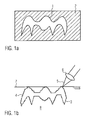
- FIG. 1 a a blank 2 is shown, from which a tooth replacement part 1 can be milled out.
- the entire hatched area of material must be removed, which is relatively time consuming is.
- the part of the blank 2, which is not used for the dental prosthesis part 1 is machined, so can not be used directly again.
- FIG. 1b is an example of a rapid prototyping method, here the supercharger internal, shown.
- the area 8 is a powdered or liquid material, which was applied in layers, for example with a slider and locally with a focused (see reference numeral 6) laser beam 5 is melted (or otherwise modified), so that subsequently, after cooling ( or the like) is solidified.
- the surface of the powder is identified by reference numeral 7.
- the tooth replacement part 3 has a relatively large surface roughness 4. This is the result of the ply-like application of the material 8 to be consolidated and the local solidification. This regularly leads to stepped surfaces.
- FIG. 2 a dental prosthesis 1 is shown enlarged in section. This is the part of a bridge to be placed on a ground tooth or implant post. The area which comes into contact with the ground tooth or the implant post is the inner area 9. A part of this inner area 9 is the area of the preparation border 10, ie the area which must be worked particularly precisely around the inner area 9 of the tooth replacement part 1 to seal well on the outside. This is important to prevent the ingress of bacteria or other tooth-destroying substances.
- the outside area is marked with reference numeral 11.
- panels or veneers such as porcelain or the like can be applied.
- the outsides 11 may, however, remain unclad.
- FIG. 3a is the inside of a dental prosthesis shown in section, as it may have been produced according to the invention with a rapid prototyping method.
- the shape produced remains within the dashed line 15.
- the line 15 indicates the shape that would optimally fit the ground tooth or implant post. This form can be indicated, for example, by a corresponding data record.
- the surface thereof lies on this line 15.
- the surface is spaced from the line 15.
- the excess material 18 can be removed with a milling tool 20.
- a milling tool 20 is shown schematically (see rotation 21), which is a Dreiachsfräsmaschine (see reference numeral 23).
- rotation 21 is a Dreiachsfräsmaschine
- FIG. 3a and 3b not shown (or only at the bottom of the approach) outside of the dental prosthesis part 1 is stepped, as they are for example in FIG. 1b is shown. This rough surface is well suited to disguise afterwards.
- FIG. 3a an output data set 15 is shown. This has been modified in such a way that an excess of material arises in the area of the preparation margin. A dental prosthesis made with the original data set 15 would not have such excess material.
- the region of the preparation margin, the inner region or any other region in which an excess of material is to be arranged can be automatically detected and / or determined.
- the in FIG. 3a Form data 15 shown to be evaluated to identify the corresponding areas.
- further data may also be present in a data record with which the regions which are to be provided with a material surplus are identified.
- the area of a preparation boundary or the interior area can be marked and this information can be exploited in order to provide a surplus of material in this area.
- FIG. 4 At 25, a rapid prototyping apparatus is shown schematically. It is shown in a state in which the workpiece produced can be seen in section and then still has to be finished upwards.
- a liquid or powdery material is provided which is locally modified so as to produce a solidified structure.
- a frame 27 can be seen, from which go webs 28 to dental prostheses 29.
- the webs 28 may also be connected to each other without a frame 27 is present.
- the tooth replacement parts 29 may also be arranged so that they are held directly by a frame 27 without webs.
- FIG. 4 illustrated variant in which a frame 27 is provided, emanate from the webs which hold the dental prosthesis parts 29.
- Two tooth replacement parts are shown by way of example, a two-part one on the left and a three-part one on the right Tooth replacement part 29.
- To each tooth replacement part 29 lead a plurality of webs 28 to keep the dental prosthesis parts 29 stable. This is advantageous for machining with the erosive method.
- a data record is used in which, in addition to the data for the tooth replacement parts, data for connectors (bars, frames, etc.) are also available.
- Such a data record can be created from one or more end data records before the rapid prototyping process begins.
- the tooth replacement parts 29 can be completely removed from the frame 27. While in FIG. 4 two tooth replacement parts 29 are shown, the method is particularly advantageous for 50, 100, 150, 200, 250 or even more dental prostheses. As a result of the connection of the tooth replacement parts 29 with a frame 27, more than 50, more than 100, 150, 200, 250 or more tooth replacement parts can be removed together from the rapid prototyping device. Furthermore, all of the dental prostheses can be put together as a workpiece in a milling device (see FIG. 4 right).
- FIG. 4 on the right is the workpiece finished with the rapid prototyping process.
- This has the frame 27 with the webs 28, which lead to the now completely shaped tooth replacement parts 29.
- the tooth replacement parts 29 retained by the webs 28 may be provided with a milling tool 20 (in FIG FIG. 4 indicated schematically below) according to, as previously explained, be post-processed.
- a milling tool 20 in FIG FIG. 4 indicated schematically below
- Other abrasive methods than milling are also possible.
- a referencing 32 is formed with which the position of the tooth replacement parts 29 can be determined for the milling process. From the manufacturing data, with which the Rapidprototyping method is performed, the geometric relationship between the dental prostheses 29 and the reference 32 is known. This known relation can be exploited to then conclude from the defined positioning of the referencing 32 to the position of the dental prosthesis parts 29.
- certain shapes such as pyramids, cuboids, rectangles, triangles, hemispheres or combinations thereof can be used. Any characteristic shape suitable for defining or identifying the position of the workpiece is suitable here.
- the referencing may be by a protruding part and / or a depression (s. Fig. 4 ) be given. In FIG. 4 For example, an element 31 of the machine for carrying out an ablation process is shown, which can be introduced into the referencing 32, or to which the referencing 32 can be guided, so that the position of the frame 27 or the tooth replacement parts 29 is clearly defined.
- the dental prosthesis parts can also initially be positioned undefined, but the position can then be determined on the basis of the referencing. Then, a milling tool or a corresponding device of a machine for a machining process can detect the position of a corresponding abrasive device, e.g. Adjust a milling head accordingly.
- optically detectable shapes or markings may be provided, such as hemispheres in a certain geometry or the like, which are optically easy to detect, and then return to the position of the tooth replacement parts 29 after the detection of the referencing.
- jaws 33 schematically, with which the frame 27 can be held for the milling process.
- the frame 27 can also be used in a suitably prepared holding frame and then fixed in this position. This is advantageous for the desired stability during milling.
- the individual dental prosthesis parts are separated from the webs by breaking or separating.
- breaking or separating For this purpose, during the rapid prototyping process or during milling (or any other ablative process), corresponding predetermined breaking points can be provided at the transitions between web or frame and the dental prosthetic item.
- correspondingly adapted devices can be provided, such as a combined rapid prototyping device with a device for an erosive method, such as a milling device or appropriately equipped computer with e.g. the mentioned computer readable media.
Landscapes
- Health & Medical Sciences (AREA)
- Engineering & Computer Science (AREA)
- Manufacturing & Machinery (AREA)
- General Health & Medical Sciences (AREA)
- Materials Engineering (AREA)
- Oral & Maxillofacial Surgery (AREA)
- Dentistry (AREA)
- Epidemiology (AREA)
- Life Sciences & Earth Sciences (AREA)
- Animal Behavior & Ethology (AREA)
- Chemical & Material Sciences (AREA)
- Public Health (AREA)
- Veterinary Medicine (AREA)
- Physics & Mathematics (AREA)
- Optics & Photonics (AREA)
- Dental Prosthetics (AREA)
Abstract
Description
- Die Erfindung betrifft ein Verfahren zum Herstellen von Zahnersatzteilen, ein Verfahren zum Erstellen eines Datensatzes sowie ein computerlesbares Medium.
- Aus dem Stand der Technik ist es bekannt, Zahnersatzteile beispielsweise mit dem Lasersintern herzustellen. Hierbei wird beispielsweise ein Metallpulver lokal aufgeschmolzen, so dass es sich nach dem Abkühlen in dem aufgeschmolzenen Bereich verfestigt. Auf diese Weise kann durch lageweises Aufbringen von Pulver und anschließendes selektives Sintern desselben ein dreidimensionales Zahnersatzteil hergestellt werden. Nachteilig bei diesem Verfahren ist, dass durch das lageweise Aufbringen von Material und das anschließende lokale Sintern sich in der Regel stufenförmige bzw. sehr raue Oberflächen ergeben. Die Präzision, die für Zahnersatzteile gewünscht wird, ist so oft nicht erreichbar.
- Weiterhin ist es aus dem Stand der Technik bekannt, Zahnersatzteile aus Vollmäterial auszufräsen. Hiermit können Zahnersatzteile mit ausreichend hoher Präzision hergestellt werden. Hierbei kann jedoch der Materialverbrauch recht erheblich sein, so dass die Herstellung kostenintensiv ist.
- Aufgabe der vorliegenden Erfindung ist es, ein Verfahren zum Herstellen von Zahnersatzteilen, ein Verfahren zum Erstellen eines Datensatzes und ein computerlesbares Medium zur Verfügung zu stellen, mit dem Zahnersatzteile möglichst kostengünstig und gleichzeitig mit ausreichend hoher Präzision hergestellt werden können.
- Diese Aufgabe wird gelöst mit einem Verfahren nach Anspruch 1 oder 12 sowie mit einem computerlesbaren Medium nach Anspruch 18.
- Bevorzugte Ausführungsformen sind in den abhängigen Ansprüchen offenbart.
- Bei dem Verfahren wird ein Zahnersatzteil mit einem Rapidprototyping-Verfahren hergestellt. Dies ist relativ schnell und kostengünstig möglich, da Material für das Zahnersatzteil nur in dem Umfang verbraucht wird, wie es konkret für ein Zahnersatzteil benötigt wird.
- Die so hergestellten Zahnersatzteile werden anschließend mit einem abtragenden Verfahren wie etwa einem Fräsverfahren bearbeitet. Hierdurch kann die gewünschte Präzision der Zahnersatzteile erreicht werden. Die Bearbeitung kann z.B. eine Nachbearbeitung sein, bei der lediglich geringe Modifikationen des Zahnersatzteils vorgenommen werden, wie etwa Glättungen von Oberflächen etc., das Zahnersatzteil aber im Wesentlichen schon fertig ist.
- Insbesondere wird hierbei beispielsweise vermieden, dass ein Werkzeug eines abtragenden Verfahrens (z.B. Fräskopf beim Fräsen) sich relativ lange damit beschäftigt Material abzutragen, das weit weg von der Oberfläche des Zahnersatzteils ist, so dass sich das Abtragen im wesentlichen auf eine Feinbearbeitung beschränken kann, die jedoch relativ schnell durchgeführt werden kann.
- Das Rapidprototyping-Verfahren kann ein Lasersinter-Verfahren sein (wie oben bereits beschrieben) oder auch jedes andere Rapidprototyping-Verfahren, wie beispielsweise die Stereolithographie, das Lasergenerieren, das Fused-depostion-modeling, das Laminatedobject-modeling, das 3-D-Drucken, Contour-crafting oder ein Multi-Jet-Modeling sowie ein Polyjet-Vertahren.
- Jedes dieser Verfahren ist geeignet, ein Zahnersatzteil herzustellen, so dass es anschließend mit einem abtragenden Verfahren wie einem Fräsverfahren (nach)bearbeitet werden kann.
- Bei Zahnersatzteilen, die verkleidet werden sollen, ist eine gewisse Oberflächenrauigkeit in bestimmten Bereichen durchaus wünschenswert. An rauen Oberflächen lassen sich beispielsweise Porzellanverkleidungen oder andere Verkleidungen gut haltend anbringen. In so fern kann die mit einem Rapidprototyping erzeugte raue Oberfläche von Vorteil sein.
- Bei einem Fräsverfahren kann ein Stahl- oder noch besser ein Diamantfräser eingesetzt werden. Mit Diamantfräsern lassen sich besonders präzise und glatte Oberflächen herstellen.
- Besonders vorteilhaft ist ein Verfahren, bei dem insbesondere der Bereich einer Präparationsgrenze bzw. der Innenbereich eines Zahnersatzteils mit dem Fräsverfahren (nach)bearbeitet wird. Insbesondere im Bereich der Präparationsgrenze ist eine möglichst exakte Form des Zahnersatzteils gewünscht, um so einen guten Abschluss zu erreichen. Auf der Außenseite ist eine Nachbearbeitung in der Regel eher nicht gewünscht, da hier eine raue Oberfläche, insbesondere zum Verkleiden, vorteilhaft sein kann. Soll das Zahnersatzteil nicht verkleidet werden, so kann jedoch auch außen eine Nachbearbeitung mit einem abtragenden Verfahren (z.B. Fräsverfahren) stattfinden.
- Weiterhin ist ein solches Verfahren vorteilhaft, bei dem mit dem Rapidprototyping-Verfahren eine Referenzierung erzeugt wird. Diese Referenzierung kann verwendet werden, um das Zahnersatzteil bzw. ein Fräswerkzeug für den Fräsvorgang zu positionieren. Anhand der Referenzierung kann also die Position des hergestellten Zahnersatzteils für den Fräsvorgang erkannt und/oder definiert werden.
- Weiterhin ist es vorteilhaft, wenn mit dem Rapidprototyping-Verfahren ein Gerüst bzw. ein Rahmen erzeugt wird, in dem Zahnersatzteile gehalten werden, so dass die Zahnersatzteile beispielsweise für das abtragende Verfahren wie etwa den Fräsvorgang mit dem Rahmen oder dem Gerüst transportiert und/oder positioniert werden können.
- Mit dem abtragenden Verfahren sollen vorteilhafter Weise insbesondere die bearbeiteten Bereiche geglättet werden.
- Weiter ist es vorteilhaft, wenn in wenigstens einem bestimmten Bereich mit dem Rapidprototyping-Verfahren ein Materialüberschuss ausgebildet wird und in diesem Bereich anschließend eine Nachbearbeitung stattfindet, wobei der Materialüberschuss (zumindest teilweise) abgetragen wird.
- Weiterhin ist es vorteilhaft, wenn in denjenigen Bereichen, in denen keine Nachbearbeitungen stattfinden soll, die erzeugte Form, die im Rapidprototyping-Verfahren hergestellt wurde, innerhalb von vorgegebenen Oberflächen verbleibt, bzw. teilweise zu dieser beabstandet ist. Insbesondere durch eine dem Rapidprototyping-Verfahren eigene Oberflächenrauigkeit ergeben sich Bereiche, die zu einer vorgegebenen Oberfläche beabstandet sind, falls die Oberfläche ansonsten insgesamt innerhalb der vorgegebenen Oberfläche verbleibt. Die vorgegebene Oberfläche kann beispielsweise diejenige sein, die gemäß einem vorgegebene Datensatz herzustellen wäre.
- Bei dem Verfahren können Zahnersatzteile aus verschiedensten Materialien hergestellt werden. So ist ein Zahnersatzteil aus Kunststoff, (glas)faserverstärktem Kunststoff aus einem glasfaserverstärkten Copolyamid möglich. Auch ist ein Metall oder eine Metalllegierung, wie beispielsweise Kobalt, Kobaltlegierung, Chromkobaltlegierung, Titan oder Titanlegierung, Gold oder eine Goldlegierung denkbar. Auch eine Keramik, wie etwas eine Zirkonkeramik (insbesondere eine yttriumstabilisierte Zirkonkeramik) oder Aluminiumoxid sind als Material des Zahnersatzteils möglich.
- Weiterhin ist eine Ausführungsform vorteilhaft, bei der ein hergestelltes Zahnersatzteil nach dem Herstellen und vor dem Bearbeiten gesintert wird. Damit lässt sich das formgebende Herstellungsverfahren des Zahnersatzteils abschließen und dadurch die exakt gewünscht Form herstellen. Ein Verziehen des Zahnersatzteils durch ein anschließendes Sintern wird somit ausgeschlossen. Es ist jedoch auch möglich, ein Zahnersatzteil erst mit einem Fräsverfahren nachzubearbeiten und anschließend dichtzusintern. Dies ist insbesondere im Bezug auf den Verschleiß von Fräswerkzeugen vorteilhaft, der bei der Bearbeitung von noch nicht ganz durchgesinterten Materialien vergleichsweise niedrig ist.
- Bei einem Verfahren zum Erstellen eines Datensatzes, wird ein Ausgangsdatensatz verwendet, um einen Enddatensatz zu erhalten. Hierbei wird ein Materialüberschuss vorgesehen. Der Materialüberschuss ergibt sich durch den Vergleich der beiden Datensätze bzw. durch zwei gemäß dem jeweiligen Datensatz hergestellten Zahnersatzteile. Die Herstellung von den zwei Zahnersatzteilen gemäß den beiden Datensätzen soll nicht Teil des Verfahrens sein, sondern lediglich dazu dienen, den Materialüberschuss zu definieren.
- Der Bereich oder die Bereiche, in denen ein Materialüberschuss vorhanden sein soll, kann automatisch bestimmt werden, wobei hierzu die Formdaten selber aber auch weitere Information in dem Ausgangsdatensatz verwendet werden kann. Die Information kann auch von einem Bediener eingegeben werden.
- In dem Ausgangsdatensatz kann z.B. der Bereich einer Präparationsgrenze und/oder der Innenbereich gespeichert sein, neben den eigentlichen Formdaten. Die Information, welcher Teil der Form bzw. der Formdaten die Präparationsgrenze und/oder den Innenbereich darstellt ist somit bereits vorhanden. Die Information kann aber auch durch eine Computeranalyse automatisch erkannt werden oder durch einen Bediener eingegeben werden.
- Mehrere Enddatensätze können auch zu einem Produktionsdatensatz weiterverarbeitet werden. Hier wird ein Datensatz erzeugt, mit dem ein Werkstück erzeugt werden kann, bei dem mehrere Zahnersatzteile mit Verbindern wie etwa Stegen, einem oder mehreren Rahmen, einem oder mehreren Gerüsten, etc. verbunden sind.
- Ein oder mehrere Enddatensätze sowie auch ein Produktionsdatensatz können zur Herstellung der Zahnersatzteile mit einem entsprechenden Rapid-Prototyping-Verfahren dienen. Die so hergestellten Zahnersatzteile und/oder das so hergestellte Werkstück können/kann anschließend mit einem abtragenden Verfahren, insbesondere mit einem Fräsverfahren bearbeitet werden.
- Die Erfindung betrifft auch einen computerlesbaren Datenträger, der Instruktionen umfasst, die eines der obigen oder weiter unten beschriebenen Verfahren durchführen, wenn sie in einen Computer eingelesen werden.
- Die Herstellung von Zahnersatzteilen kann also mit zwei verschiedenen computergestützten Herstellungsverfahren erfolgen, die nacheinander durchgeführt werden. Die Herstellung kann weiter batchweise (chargenweise) erfolgen. D.h. erst wird eine größere Anzahl von Zahnersatzteilen mit den ersten computergestützten Verfahren hergestellt und anschließend (nach Abschluss des ersten Verfahrens für alle damit hergestellten Zahnersatzteile) mit dem zweiten computergestützten Verfahren bearbeitet. Es können mehr als 50, 100, 150, 200 oder 250 Zahnersatzteile in einer Charge hergestellt werden.
- Die Zahnersatzteile können Inlays, Overlays, Onlays, Käppchen, Kronen, Primärkronen, Sekundärkronen, Brücken, Gerüste, künstliche Gebisse (dritte Zähne), Abutments, Implantate, etc. sein.
- Bevorzugte Ausführungsform des Verfahrens sollen anhand der beiliegenden Figuren erläutert werden. Dabei zeigt:
- Figur 1:
- die konventionelle Herstellung von Zahnersatzteilen;
- Figur 2:
- bestimmte typische Bereiche von Zahnersatzteilen;
- Figur 3:
- die Form von Zahnersatzteilen gemäß einer Ausführungsform der Erfindung;
- Figur 4:
- eine schematische Darstellung des Herstellungsverfahrens.
- In
Figur 1 a ist ein Rohling 2 gezeigt, aus dem ein Zahnersatzteil 1 ausgefräst werden kann. Hierzu muss der gesamte schraffierte Bereich an Material entfernt werden, was relativ Zeitaufwendig ist. Weiterhin ist bei diesem Fräsverfahren zu berücksichtigen, dass derjenige Teil des Rohlings 2, der nicht für das Zahnersatzteil 1 verwendet wird, zerspant wird, also nicht unmittelbar wieder verwendet werden kann. - In
Figur 1b ist ein Beispiel eines Rapidprototyping-Verfahrens, hier des Ladersinterns, gezeigt. Im Bereich 8 befindet sich ein pulverförmiges oder flüssiges Material, das schichtweise, beispielsweise mit einem Schieber aufgetragen wurde und lokal mit einem fokussierten (siehe Bezugszeichen 6) Laserstrahl 5 aufgeschmolzen (oder sonst wie modifiziert) wird, so dass es anschließend, nach dem Abkühlen (oder Ähnlichem), verfestigt ist. Die Oberfläche des Pulvers ist mit Bezugszeichen 7 gekennzeichnet. - In der Schnittdarstellung in
Figur 1b weist das Zahnersatzteil 3 eine relativ große Oberflächenrauigkeit 4 auf. Dies ist die Folge des lagenartigen Aufbringens des zu verfestigenden Materials 8 und des lokalen Verfestigens. Dies führt regelmäßig zu stufenförmigen Oberflächen. - In
Figur 2 ist ein Zahnersatzteil 1 im Schnitt vergrößert dargestellt. Es handelt sich hierbei um denjenigen Teil einer Brücke, der auf einen beschliffenen Zahn oder Implantatspfosten aufgesetzt werden soll. Derjenige Bereich, der mit dem beschliffenen Zahn oder dem Implantatspfosten in Kontakt kommt, ist der Innenbereich 9. Ein Teil dieses Innenbereichs 9 ist der Bereich der Präparationsgrenze 10, also derjenige Bereich, der besonders präzise gearbeitet sein muss, um den Innenbereich 9 des Zahnersatzteils 1 nach außen hin gut abzudichten. Dies ist wichtig, um das Eindringen von Bakterien oder anderen zahnzerstörenden Substanzen zu verhindern. - Der Außenbereich ist mit Bezugsziffer 11 gekennzeichnet. Auf den Außenbereich können Verkleidungen bzw. Verblendungen wie beispielsweise aus Porzellan o. ä. aufgebracht werden. Die Außenseiten 11 können jedoch auch unverkleidet bleiben.
- In
Figur 3a ist die Innenseite eines Zahnersatzteils im Schnitt gezeigt, wie es erfindungsgemäß mit einem Rapidprototyping-Verfahren hergestellt worden sein kann. Im oben liegenden Teil der Innenseite bleibt die hergestellte Form innerhalb der gestrichelt dargestellten Linie 15. Die Linie 15 gibt diejenige Form an, die optimal zu dem beschliffenen Zahn oder Implantatspfosten passen würde. Diese Form kann beispielsweise durch einen entsprechenden Datensatz angegeben sein. In den Bereichen 17 der stufenförmigen Oberfläche des Zahnersatzteils liegt die Oberfläche desselben auf dieser Linie 15. In den Ecken 16 ist die Oberfläche von der Linie 15 beabstandet. Hier liegt beispielsweise ein Abstand d3 vor. - In den Bereichen der Präparationsgrenze 10 (siehe
Figur 2 ) steht die Oberfläche des hergestellten Zahnersatzteils über die Linie 15 nach außen über. Sowohl die konkaven Ecken (siehe Abstand d1) als auch die konvexen Ecken (Abstand d2) befinden sich außerhalb der Begrenzungsoberfläche 15. Hier ist ein Materialüberschuss 18 vorgesehen. - Bei der in
Figur 3a rechten Seite der Präparationsgrenze liegen die Ecken 19 zwar von außen kommend auf der Linie 15, jedoch ist auch hier ein Materialüberschuss in den übrigen Bereichen gegeben. - Der Materialüberschuss 18 kann mit einem Fräswerkzeug 20 abgetragen werden. In
Figur 3a ist ein solches Fräswerkzeug schematisch dargestellt (siehe Drehung 21), wobei es sich hierbei um eine Dreiachsfräsmaschine (siehe Bezugszeichen 23) handelt. Es können jedoch auch 3 + 1, 4- oder 5-achsige Fräsmaschinen vorgesehen sein. - Das Ergebnis einer (Nach-)Bearbeitung des Bereichs der Präparationsgrenze 10 ist in
Figur 3b gezeigt. Hier werden glatte Oberflächen 24 erzeugt, die möglichst exakt auf der gewünschten Linie 15 (gestrichelte Linie) liegen. - Während in
Figur 3 der Fall gezeigt ist, bei dem lediglich im Bereich der Präparationsgrenze 10 (sieheFigur 2 ) ein Materialüberschuss vorhanden ist, besteht auch die Möglichkeit, die gesamte Innenseite 9 (sieheFigur 2 ) mit einem Materialüberschuss zu versehen und anschließend mit dem abtragenden Verfahren nachzubearbeiten. So wird dieser Bereich, der für einen guten Halt des Zahnersatzteils sorgt und der möglichst exakt die gewünschte Form aufweisen soll, besonders exakt gefertigt. - Die in
Figur 3a und3b nicht (bzw. nur unten im Ansatz) dargestellte Außenseite des Zahnersatzteils 1 ist stufenförmig, wie sie beispielsweise inFigur 1b gezeigt ist. Diese raue Oberfläche ist gut geeignet, um sie anschließend zu verkleiden. - Erfindungsgemäß ist es jedoch auch möglich, auch die Außenseite 11 oder einen Teil davon mit dem Fräsverfahren nachzubearbeiten. Auch kann auf der gesamten Außenseite oder einem Teil der Außenseite ein Materialüberschuss vorhanden sein.
- Selbst wenn die gesamte Oberfläche des Zahnersatzteils, das mit dem Rapidprototyping-Verfahren hergestellt wurde, mit dem Fräsverfahren nachbearbeitet wird, so ergibt sich hier ein relativ schneller Fräsvorgang, da es in der Regel ausreicht, mit dem Fräswerkzeug über die Oberfläche einmal drüber zu streichen. Ein Abtragen von Volumenmaterial, wie es beispielsweise zum Formen der Aushöhlung der im Bereich der Innenseite 9 gegebenen Aushöhlung notwenig ist, kann hier entfallen. Die Fräsbearbeitung ist so relativ zügig durchführbar. Dies gilt allgemein für jedes abtragende Verfahren. Weiterhin wird hierbei relativ wenig Material zerspant, so dass die Herstellungskosten niedrig bleiben.
- In
Figur 3a ist ein Ausgangsdatensatz 15 gezeigt. Dieser ist so modifiziert worden, dass in dem Bereich der Präparationsgrenze ein Materialüberschuss entsteht. Ein Zahnersatzteil, das mit dem Ausgangsdatensatz 15 hergestellt worden wäre, hätte einen solchen Materialüberschuss nicht. - Der Bereich der Präparationsgrenze, der Innenbereich oder jeder andere Bereich, in dem ein Materialüberschuss angeordnet werden soll, kann automatisch erkannt und/oder festgelegt werden. So können z.B. die in
Figur 3a gezeigten Formdaten 15 ausgewertet werden, um die entsprechenden Bereiche zu identifizieren. Auch können in einem Datensatz neben den eigentlichen Formdaten auch noch weitere Daten vorhanden sein, mit denen die Bereiche, die mit einem Materialüberschuss versehen werden sollen, gekennzeichnet sind. So kann z.B. der Bereich einer Präparationsgrenze oder der Innenbereich gekennzeichnet sein und diese Information ausgenutzt werden, um einen Materialüberschuss in diesem Bereich vorzusehen. - In
Figur 4 ist unter Bezugszeichen 25 eine Rapidprototyping-Vorrichtung schematisch dargestellt. Sie ist in einem Zustand gezeigt, bei dem das hergestellte Werkstück im Schnitt zu erkennen ist und anschließend noch nach oben hin fertig gestellt werden muss. In einem Becken ist ein flüssiges oder pulverförmiges Material vorgesehen, das lokal modifiziert wird, um so eine verfestigte Struktur zu fertigen. InFigur 4 ist ein Rahmen 27 zu erkennen, von dem aus Stege 28 zu Zahnersatzteilen 29 gehen. Die Stege 28 können auch so miteinander verbunden sein, ohne dass ein Rahmen 27 vorliegt. Weiterhin können die Zahnersatzteile 29 auch so angeordnet sein, dass sie ohne Stege direkt von einem Rahmen 27 gehalten werden. Bevorzugt ist jedoch die inFigur 4 dargestellte Variante, bei der ein Rahmen 27 vorhanden ist, von dem Stege ausgehen, die die Zahnersatzteile 29 halten. Es sind beispielhaft zwei Zahnersatzteile gezeigt, links ein zweigliedriges und rechts ein dreigliedriges Zahnersatzteil 29. Zu jedem Zahnersatzteil 29 führen mehrere Stege 28, um die Zahnersatzteile 29 stabil zu halten. Dies ist für die Bearbeitung mit dem abtragenden Verfahren vorteilhaft. - Zur Durchführung des Rapid-Prototyping-Verfahrens wird ein Datensatz verwendet, in dem neben den Daten für die Zahnersatzteile auch Daten für Verbinder (Stege, Rahmen etc.) vorhanden sind. Ein solcher Datensatz kann vor Beginn des Rapid-Prototyping-Verfahrens aus einem oder mehreren Enddatensätzen erstellt werden.
- Nach dem Durchführen des Rapidprototyping-Verfahrens können die Zahnersatzteile 29 komplett an dem Rahmen 27 herausgenommen werden. Während in
Figur 4 zwei Zahnersatzteile 29 gezeigt sind, ist das Verfahren insbesondere für 50, 100, 150, 200, 250 oder noch mehr Zahnersatzteile vorteilhaft. Durch die Verbindung der Zahnersatzteile 29 mit einem Rahmen 27 können so auch mehr als 50, mehr als 100, 150, 200, 250 oder mehr Zahnersatzteile zusammen aus der Rapidprototyping-Vorrichtung entnommen werden. Weiterhin können alle Zahnersatzteile zusammen als ein Werkstück in eine Fräsvorrichtung (sieheFigur 4 rechts) überführt werden. - In
Figur 4 rechts ist das mit dem Rapidprototyping-Verfahren fertig gestellte Werkstück dargestellt. Dieses weist den Rahmen 27 mit den Stegen 28 auf, die zu den nun vollständig geformten Zahnersatzteilen 29 führen. Die durch die Stege 28 gehaltenen Zahnersatzteile 29 können mit einem Fräswerkzeug 20 (inFigur 4 unten schematisch angedeutet) entsprechend, wie vorher erklärt, nachbearbeitet werden. Andere abtragende Verfahren als das Fräsen sind auch möglich. - Vorteilhaft ist, wenn eine Referenzierung 32 ausgebildet wird, mit der die Position der Zahnersatzteile 29 für den Fräsvorgang bestimmbar ist. Aus den Herstellungsdaten, mit denen das Rapidprototyping-Verfahren durchgeführt wird, ist die geometrische Beziehung zwischen den Zahnersatzteilen 29 und der Referenzierung 32 bekannt. Diese bekannte Relation kann dazu ausgenutzt werden, um aus der definierten Positionierung der Referenzierung 32 dann auf die Position der Zahnersatzteile 29 zu schließen. Zur Referenzierung können auch bestimmte Formen, wie Pyramiden, Quader, Rechtecke, Dreiecke, Halbkugeln oder Kombinationen hieraus eingesetzt werden. Jegliche charakteristische Form, die geeignet ist, um die Position des Werkstücks zu definieren bzw. zu identifizieren, ist hier geeignet. Die Referenzierung kann durch einen hervorstehenden Teil und/oder eine Vertiefung (s.
Fig. 4 ) gegeben sein. InFigur 4 ist beispielsweise ein Element 31 der Maschine zur Durchführung eines abtragenden Verfahrens dargestellt, das in die Referenzierung 32 eingebracht werden kann, oder auf das die Referenzierung 32 geführt werden kann, so dass die Position des Rahmens 27 bzw. der Zahnersatzteile 29 eindeutig definiert ist. - Ebenso, wie es also möglich ist, durch eine Referenzierung die Zahnersatzteile wohldefiniert zu Positionieren, können die Zahnersatzteile auch zunächst undefiniert positioniert werden, die Position dann aber bestimmt werden, anhand der Referenzierung. Dann kann ein Fräswerkzeug oder eine entsprechende Einrichtung einer Maschine für ein abtragendes Verfahren die Position von einer entsprechenden abtragenden Einrichtung z.B. einem Fräskopf entsprechend anpassen.
- Es können also zum Beispiel auch lediglich optisch detektierbare Formen oder Markierungen vorgesehen sein, wie beispielsweise Halbkugeln in einer bestimmten Geometrie oder ähnliches, die optisch leicht zu detektieren sind, um dann nach der Detektion der Referenzierung auf die Position der Zahnersatzteile 29 zurückzuschließen.
- In
Figur 4 sind noch Klemmbacken 33 schematisch gezeigt, mit denen der Rahmen 27 für den Fräsvorgang gehalten werden kann. Der Rahmen 27 kann auch in einen entsprechend vorbereiteten Halterahmen eingesetzt werden und anschließend in dieser Position fixiert werden. Dies ist für die gewünschte Stabilität bei der Fräsbearbeitung vorteilhaft. Es können auch mehr als zwei, drei, vier oder fünf Mittel zum Halten und/oder Fixieren/Definieren der Position des Werkstücks vorgesehen sein. - Nach der Behandlung mit dem Fräsvorgang, werden die einzelnen Zahnersatzteile von den Stegen durch Rausbrechen, oder Abtrennen getrennt. Hierzu können bei dem Rapidprototyping-Verfahren oder bei dem Fräsen (oder jedem anderen abtragenden Verfahren) entsprechende Sollbruchstellen an den Übergängen zwischen Steg oder Rahmen und dem Zahnersatzteil vorgesehen werden.
- Zur Durchführung der Verfahren können erfindungsgemäß entsprechend angepasste Vorrichtungen vorgesehen sein, wie etwa eine kombinierte Rapidprototyping-Vorrichtung mit einer Einrichtung für ein abtragendes Verfahren wie etwa eine Fräseinrichtung oder entsprechend ausgerüstete Computer mit z.B. den erwähnten computerlesbaren Medien.
Claims (18)
- Verfahren zum Herstellen von einem oder mehreren Zahnersatzteilen (29) mit den Schritten:Durchführen eines Rapid-Prototyping-Verfahrens zum Herstellen von einem oder mehreren Zahnersatzteilen (29) undanschließendes Bearbeiten, wie etwa ein Nachbearbeiten, von dem einen oder mehreren Zahnersatzteilen (29) mit einem abtragenden Verfahren wie etwa einem Fräsverfahren.
- Verfahren nach Anspruch 1,
dadurch gekennzeichnet, dass
das Rapidprototypingverfahren ein Lasersintem, Stereolithographie, Lasergenerieren, Fused Deposition Modeling, Laminated Object Modeling, 3D-Drucken, Contour Crafting, Multijet-Modeling, oder ein Polyjet-Vertahren ist oder umfasst. - Verfahren nach Anspruch 1 oder 2,
dadurch gekennzeichnet, dass
das abtragende Verfahren einen Stahl- oder Diamantfräser (20) einsetzt. - Verfahren nach einem der Ansprüche 1 bis 3,
dadurch gekennzeichnet, dass
bei der anschließenden Bearbeitung insbesondere der Bereich der Präparationsgrenze (10) und/oder der Innenbereich (9) des Zahnersatzteils (1) bearbeitet werden. - Verfahren nach einem der Ansprüche 1 bis 4,
dadurch gekennzeichnet, dass
mit dem Rapid-Prototyping-Verfahren eine Referenzierung (32) erzeugt wird, die mit dem einen oder mehreren Zahnersatzteilen (29) verbunden ist und diese Referenzierung (32) zum Positionieren des Zahnersatzteils (29) und/oder eines Werkzeugs (20) für das abtragende Verfahren verwendet wird. - Verfahren nach einem der Ansprüche 1 bis 5,
dadurch gekennzeichnet, dass
ein Gerüst und/oder ein Rahmen (27) mit dem Rapid-Prototyping-Verfahren erzeugt wird, mit dem die erzeugten Zahnersatzteile (29) für die anschließende Bearbeitung positioniert und/oder gehalten werden können. - Verfahren nach einem der Ansprüche 1 bis 6,
dadurch gekennzeichnet, dass
mit dem abtragenden Verfahren die Oberfläche in dem bearbeiteten Bereich geglättet wird. - Verfahren nach einem der Ansprüche 1 bis 7,
dadurch gekennzeichnet, dass
bei dem Rapid-Prototyping-Verfahren in einem vorbestimmten Bereich ein Materialüberschuss (18) ausgebildet wird, wobei in diesem Bereich die anschließende Bearbeitung stattfindet. - Verfahren nach einem der Ansprüche 1 bis 8,
dadurch gekennzeichnet, dass
in denjenigen Bereichen, in denen keine anschließende Bearbeitung stattfinden wird, die erzeugte Form innerhalb von vorgegebenen Oberflächen verbleibt und teilweise zu dieser beabstandet ist, insbesondere durch eine dem Rapidprotoyping-Verfahren eigene Oberflächenrauigkeit. - Verfahren nach einem der Ansprüche 1 bis 9,
dadurch gekennzeichnet, dass
das Zahnersatzteil (29) aus Kunststoff, einem glasfaserverstärktem Kunststoff, einem glasfaserverstärktem Copolyamid, Kobalt oder Kobaltlegierungen, einer ChromKobaltlegierung, Titan oder einer Titanlegierung, Gold oder einer Goldlegierung, einer Keramik, einer Zirkonkeramik oder Aluminiumoxid hergestellt wird. - Verfahren nach einem der Ansprüche 1 bis 10,
dadurch gekennzeichnet, dass
das hergestellte Zahnersatzteil vor der anschließenden Bearbeitung gesintert wird. - Verfahren zum Erstellen eines Datensatzes, der für ein Rapid-Prototyping-Verfahren zum Herstellen eines Zahnersatzteils (29) verwendet werden kann, bei dem aus einem Ausgangsdatensatz (15) ein Enddatensatz erhalten wird, so dass in wenigstens einem Bereich eines mit dem Enddatensatz hergestellten Zahnersatzteils ein Materialüberschuss (18) vorhanden ist im Vergleich zu einem mit dem Ausgangsdatensatz hergestellten Zahnersatzteil.
- Verfahren nach Anspruch 12, dadurch gekennzeichnet, dass derjenige Bereich, in dem ein Materialüberschuss (18) vorgesehen wird, automatisch erkannt wird oder von einem Bediener vorgegeben wird oder aus spezifischer Information in dem Ausgangsdatensatz ausgelesen wird.
- Verfahren nach Anspruch 12 oder 13, dadurch gekennzeichnet, dass ein Materialüberschuss (18) im Bereich der Präparationsgrenze (10) und/oder im Bereich der Innenseite (9) des Zahnersatzteils vorgesehen wird.
- Verfahren nach einem der Ansprüche 12 bis 14, dadurch gekennzeichnet, dass mehrere Ausgangsdatensätze von verschiedenen Zahnersatzteilen zu Enddatensätzen verändert werden, und die mehreren Enddatensätze zu einem Produktionsdatensatz zusammengefasst werden, bei dem Verbinder wie etwa Stege (28), ein oder mehrere Rahmen (27) oder ein oder mehrere Gerüste vorgesehen werden, die die verschiedenen Zahnersatzteile (29) miteinander verbinden.
- Verfahren zum Herstellen eines Zahnersatzteils, bei dem ein Verfahren nach einem der Ansprüche 12 bis 15 durchgeführt wird und anschließend das Zahnersatzteil/die Zahnersatzteile mit einem Rapid-Prototyping-Verfahren mit dem Enddatensatz/dem Produktionsdatensatz hergestellt wird/werden.
- Verfahren nach Anspruch 16, dadurch gekennzeichnet, dass das hergestellte Zahnerstazteil/die hergestellten Zahnersatzteile anschließend mit einem abtragenden Verfahren wie etwa einem Fräsverfahren bearbeitet wird/werden, insbesondere im Bereich, der mit einem Materialüberschuss (18) versehen ist.
- Computerlesbares Medium mit Instruktionen, die in einen Computer geladen ein Verfahren nach einem der Ansprüche 1 bis 17 ausführen.
Applications Claiming Priority (1)
| Application Number | Priority Date | Filing Date | Title |
|---|---|---|---|
| DE102007014985A DE102007014985A1 (de) | 2007-03-28 | 2007-03-28 | Verfahren zum Herstellen von Zahnersatzteilen, Verfahren zum Erstellen eines Datensatzes und computerlesbares Medium |
Publications (2)
| Publication Number | Publication Date |
|---|---|
| EP1974688A1 true EP1974688A1 (de) | 2008-10-01 |
| EP1974688B1 EP1974688B1 (de) | 2016-01-13 |
Family
ID=39474032
Family Applications (1)
| Application Number | Title | Priority Date | Filing Date |
|---|---|---|---|
| EP08005998.3A Revoked EP1974688B1 (de) | 2007-03-28 | 2008-03-28 | Verfahren zum Herstellen von Zahnersatzteilen, Verfahren zum Erstellen eines Datensatzes und computerlesbares Medium |
Country Status (4)
| Country | Link |
|---|---|
| US (1) | US8021154B2 (de) |
| EP (1) | EP1974688B1 (de) |
| DE (1) | DE102007014985A1 (de) |
| ES (1) | ES2566732T3 (de) |
Cited By (14)
| Publication number | Priority date | Publication date | Assignee | Title |
|---|---|---|---|---|
| WO2010003882A3 (de) * | 2008-07-08 | 2010-03-04 | Bego Medical Gmbh | Duales herstellungverfahren und duale herstellungsvorrichtung fur kleinserienprodukte |
| EP2196166A1 (de) * | 2008-12-09 | 2010-06-16 | Josef Hintersehr | Verfahren zur genauen Fertigung von Dentalkomponenten mit einem Sinter oder SLM Verfahren |
| WO2013167904A1 (en) * | 2012-05-10 | 2013-11-14 | Renishaw Plc | Method of manufacturing an article |
| US8770975B2 (en) | 2008-12-15 | 2014-07-08 | 3M Innovative Properties Company | Method of making a dental restoration from a frame and a veneer |
| US9579172B2 (en) | 2007-05-15 | 2017-02-28 | 3M Innovative Properties Company | Method of making a facing for a dental restoration, facing for a dental restoration, and method of making a dental restoration |
| US9668863B2 (en) | 2009-08-19 | 2017-06-06 | Smith & Nephew, Inc. | Porous implant structures |
| EP2637598B1 (de) | 2010-11-10 | 2017-07-19 | Heraeus Kulzer GmbH | Dentalbrücken und superstrukturen und verfahren zu deren herstellung |
| US9918811B2 (en) | 2012-05-10 | 2018-03-20 | Renishaw Plc | Method of manufacturing an article |
| CN109069240A (zh) * | 2016-04-28 | 2018-12-21 | 斯特劳曼控股公司 | 用于制造牙科装置的系统和方法 |
| DE102017212182A1 (de) | 2017-07-17 | 2019-01-17 | Trumpf Laser- Und Systemtechnik Gmbh | Verfahren zum Herstellen mindestens eines Teils aus Edelmetall und/oder biokompatiblem Werkstoff |
| US20190247169A1 (en) * | 2016-10-10 | 2019-08-15 | 3Shape A/S | Common Placement Support for Artificial Teeth |
| EP3653167A1 (de) * | 2018-11-15 | 2020-05-20 | Sirona Dental Systems GmbH | Verfahren zur herstellung von dentalen passkörpern und werkstück für diesen zweck |
| EP3892402A1 (de) * | 2020-04-06 | 2021-10-13 | Siemens Aktiengesellschaft | Positionierungsmittel für generative fertigung |
| EP3919023A1 (de) | 2020-01-20 | 2021-12-08 | Nicola Zucchini | System zur herstellung von künstlichen zähnen |
Families Citing this family (46)
| Publication number | Priority date | Publication date | Assignee | Title |
|---|---|---|---|---|
| US8439926B2 (en) | 2001-05-25 | 2013-05-14 | Conformis, Inc. | Patient selectable joint arthroplasty devices and surgical tools |
| GB0501464D0 (en) * | 2005-01-25 | 2005-03-02 | Leuven K U Res & Dev | Procedure for design and production of implant-based frameworks for complex dental prostheses |
| EP1906862B1 (de) | 2005-06-30 | 2018-05-23 | Biomet 3i, LLC | Verfahren zur erstellung eines models für einen dentallabor |
| US11219511B2 (en) | 2005-10-24 | 2022-01-11 | Biomet 3I, Llc | Methods for placing an implant analog in a physical model of the patient's mouth |
| US8257083B2 (en) | 2005-10-24 | 2012-09-04 | Biomet 3I, Llc | Methods for placing an implant analog in a physical model of the patient's mouth |
| US8206153B2 (en) | 2007-05-18 | 2012-06-26 | Biomet 3I, Inc. | Method for selecting implant components |
| US8568897B2 (en) | 2007-07-20 | 2013-10-29 | Ivoclar Vivadent Ag | Addressable matrices/cluster blanks for dental CAD/CAM systems and optimization thereof |
| US8551622B2 (en) | 2007-07-20 | 2013-10-08 | Ivoclar Vivadent Ag | Addressable matrices/cluster blanks for dental CAD/CAM systems and optimization thereof |
| EP2060240A3 (de) | 2007-11-16 | 2009-08-12 | Biomet 3i, LLC | Komponenten zur Verwendung mit einer chirurgischen Schablone für eine Zahnimplantatplatzierung |
| ES2683119T3 (es) | 2008-04-15 | 2018-09-25 | Biomet 3I, Llc | Método de creación de un modelo dental digital preciso de huesos y tejidos blandos |
| EP3000430B1 (de) | 2008-04-16 | 2017-11-15 | Biomet 3i, LLC | Verfahren zur virtuellen entwicklung einer chirurgischen führung für zahnärztliche implantate |
| US20100217270A1 (en) * | 2009-02-25 | 2010-08-26 | Conformis, Inc. | Integrated Production of Patient-Specific Implants and Instrumentation |
| BE1018492A3 (de) | 2009-06-02 | 2011-01-11 | Layerwise N V | |
| ES2394385B1 (es) * | 2009-10-16 | 2013-12-13 | Juan Carlos Garcia Aparicio | Procedimiento de fabricacion de piezas sinterizadas y piezas obtenidas por dicho procedimiento |
| IT1399388B1 (it) * | 2010-04-08 | 2013-04-16 | 3Dfast S R L | Procedimento di realizzazione di protesi dentarie, attrezzatura di presa particolarmente utile per attuarlo e semilavorato, particolarmente tramite esso realizzabile |
| EP2450000A1 (de) | 2010-11-09 | 2012-05-09 | 3M Innovative Properties Company | Verfahren zur Herstellung eines Zahnartikels, mit diesem Verfahren erhaltener Artikel und Verwendungen dafür |
| DE102010052029A1 (de) * | 2010-11-23 | 2012-05-24 | Kind Hörgeräte Gmbh & Co. Kg | Ohrhörer zum Tragen im Ohr eines Nutzers |
| ES2477288T3 (es) | 2010-12-07 | 2014-07-16 | Biomet 3I, Llc | Elemento de exploración universal para su uso en un implante dental y en análogos de implante dental |
| AU2012255865B8 (en) | 2011-05-16 | 2015-06-04 | Biomet 3I, Llc | Temporary abutment with combination of scanning features and provisionalization features |
| DE102011119839B4 (de) | 2011-12-01 | 2019-11-28 | Kulzer Gmbh | Herstellen von Suprakonstruktionen auf einer SLM-Anlage mit anschließender Fräsbearbeitung der Anschlussgeometrie |
| US9408686B1 (en) | 2012-01-20 | 2016-08-09 | Conformis, Inc. | Devices, systems and methods for manufacturing orthopedic implants |
| US9452032B2 (en) | 2012-01-23 | 2016-09-27 | Biomet 3I, Llc | Soft tissue preservation temporary (shell) immediate-implant abutment with biological active surface |
| US9089382B2 (en) | 2012-01-23 | 2015-07-28 | Biomet 3I, Llc | Method and apparatus for recording spatial gingival soft tissue relationship to implant placement within alveolar bone for immediate-implant placement |
| GB201210120D0 (en) * | 2012-05-10 | 2012-07-25 | Renishaw Plc | Laser sintered part and method of manufacture |
| KR20140033826A (ko) * | 2012-09-11 | 2014-03-19 | 김도현 | 환자맞춤형 어버트먼트 가공방법 |
| US20140080092A1 (en) | 2012-09-14 | 2014-03-20 | Biomet 3I, Llc | Temporary dental prosthesis for use in developing final dental prosthesis |
| US9636229B2 (en) | 2012-09-20 | 2017-05-02 | Conformis, Inc. | Solid freeform fabrication of implant components |
| CN104780872B (zh) | 2012-09-21 | 2017-04-05 | 康复米斯公司 | 使用自由实体制造优化植入物组件的设计和制造的方法和系统 |
| US10383709B2 (en) | 2012-10-12 | 2019-08-20 | Nobel Biocare Services Ag | Dental bar |
| US8926328B2 (en) | 2012-12-27 | 2015-01-06 | Biomet 3I, Llc | Jigs for placing dental implant analogs in models and methods of doing the same |
| US9801699B2 (en) | 2013-03-14 | 2017-10-31 | Devin Okay | Paired templates for placing dental implants and enhancing registration for denture prosthetics attached to the implants |
| CN105377181A (zh) * | 2013-05-27 | 2016-03-02 | 维他牙科产品有限公司 | 用于制造牙科修复体的修复体预制件 |
| FR3012736B1 (fr) * | 2013-11-05 | 2018-01-12 | Lyra Holding | Fabrication d'un pilier implantaire par impression 3d |
| US9545302B2 (en) | 2013-11-20 | 2017-01-17 | Dermagenesis Llc | Skin printing and auto-grafting |
| EP3094283A4 (de) | 2013-12-20 | 2018-01-24 | Biomet 3i, LLC | Zahnärztliches system zur entwicklung von angepassten prothesen durch abtasten von codierten elementen |
| CH709687B1 (de) | 2014-05-23 | 2018-03-29 | Digital Smile Gmbh | Kieferorthopädische Apparatur und Verfahren zur Herstellung einer kieferorthopädischen Apparatur. |
| US9700390B2 (en) | 2014-08-22 | 2017-07-11 | Biomet 3I, Llc | Soft-tissue preservation arrangement and method |
| EP3267936A4 (de) | 2015-03-09 | 2018-12-26 | Stephen J. Chu | Eiförmiges zahnfleisch-pontic und verfahren zur verwendung davon |
| US10987201B2 (en) | 2016-02-23 | 2021-04-27 | Paltop Advanced Dental Solutions Ltd. | Dental implant |
| JP6901496B2 (ja) * | 2016-04-12 | 2021-07-14 | ノベル バイオケア サーヴィシィズ アーゲー | 歯科修復物の製造方法 |
| WO2018123023A1 (ja) | 2016-12-28 | 2018-07-05 | 三菱電機株式会社 | 積層造形支援装置、積層造形支援方法、および積層造形支援プログラム |
| LU100319B1 (en) * | 2017-06-20 | 2018-12-20 | Laboratoire Dentaire Hornbeck Jacques S A R L | Mounting element for production of a dental prosthesis, a prosthesis and method of manufacturing same |
| US10987196B2 (en) | 2018-06-27 | 2021-04-27 | Paltop Advanced Dental Solutions Ltd. | Drill guide |
| US12491047B2 (en) * | 2018-10-25 | 2025-12-09 | Solventum Intellectual Property Company | 3D-printed dental restoration precursor with support element and process of production |
| WO2020198331A1 (en) * | 2019-03-25 | 2020-10-01 | Align Technology, Inc. | Various structured supports for 3d printed aligners/mouth pieces |
| WO2021056367A1 (zh) * | 2019-09-27 | 2021-04-01 | 广州市健齿生物科技有限公司 | 一种基于增减材加工方式的定制化多孔牙桥及其制造方法 |
Citations (7)
| Publication number | Priority date | Publication date | Assignee | Title |
|---|---|---|---|---|
| US5997681A (en) | 1997-03-26 | 1999-12-07 | Kinzie; Norman F. | Method and apparatus for the manufacture of three-dimensional objects |
| DE102004009127A1 (de) | 2004-02-25 | 2005-09-15 | Bego Medical Ag | Verfahren und Vorrichtung zum Herstellen von Produkten durch Sintern und/oder Schmelzen |
| US7153135B1 (en) * | 1999-11-15 | 2006-12-26 | Thomas Richard J | Method for automatically creating a denture using laser altimetry to create a digital 3-D oral cavity model and using a digital internet connection to a rapid stereolithographic modeling machine |
| WO2007005490A2 (en) * | 2005-06-30 | 2007-01-11 | Implant Innovations, Inc. | Method for manufacturing dental implant components |
| EP1759682A2 (de) * | 2005-08-10 | 2007-03-07 | BEGO Bremer Goldschlägerei Wilh. Herbst GmbH & Co. KG | Verfahren zur Herstellung metallischer Bauteile, entsprechende metallische Bauteile sowie Kit zur Durchführung des Verfahrens |
| EP1764061A1 (de) | 2005-09-16 | 2007-03-21 | Leader Italia S.r.l. | Verfahren zur Herstellung einer dentalen enossallen Implantationsstruktur mit einer vorbestimmten Oberflächengeometrie |
| US20080241788A1 (en) | 2007-03-19 | 2008-10-02 | Degudent Gmbh | Method for the manufacture of dental prostheses |
Family Cites Families (41)
| Publication number | Priority date | Publication date | Assignee | Title |
|---|---|---|---|---|
| US2345305A (en) | 1941-05-03 | 1944-03-28 | Dentists Supply Co | Method of forming artificial teeth |
| US2528219A (en) | 1947-03-11 | 1950-10-31 | Austenal Lab Inc | Method of making thermoplastic articles |
| US2654949A (en) | 1949-02-23 | 1953-10-13 | Dentists Supply Co | Artificial tooth and method of forming the same |
| US2846725A (en) | 1955-01-18 | 1958-08-12 | Tryfus Frederic | Apparatus for making combination artificial teeth and display carrier |
| US4300862A (en) * | 1979-09-05 | 1981-11-17 | Dijet Industrial Co., Ltd. | End milling tool |
| US5027281A (en) | 1989-06-09 | 1991-06-25 | Regents Of The University Of Minnesota | Method and apparatus for scanning and recording of coordinates describing three dimensional objects of complex and unique geometry |
| US5545039A (en) * | 1990-04-10 | 1996-08-13 | Mushabac; David R. | Method and apparatus for preparing tooth or modifying dental restoration |
| US5289383A (en) * | 1990-05-17 | 1994-02-22 | Sony Corporation | Method for establishing data defining tool path for rough machining |
| US5378154A (en) * | 1992-04-06 | 1995-01-03 | Elephant Holding B.V. | Dental prosthesis and method for manufacturing a dental prosthesis |
| DE19601894C2 (de) * | 1996-01-19 | 1998-02-19 | Biagio Cicchetti | Haltevorrichtung zur Herstellung von Zahnbrücken und Herstellungsverfahren zum Herstellen von Zahnbrücken |
| US20050023710A1 (en) | 1998-07-10 | 2005-02-03 | Dmitri Brodkin | Solid free-form fabrication methods for the production of dental restorations |
| US20020187458A1 (en) * | 1999-01-19 | 2002-12-12 | Bego Bremer Goldschlagerei Wilh. Herbst Gmbh & Co. | Method for producing tooth replacements and auxiliary dental parts |
| TW461806B (en) * | 1999-08-02 | 2001-11-01 | Advance Kk | Method of manufacturing dental prosthesis, method of placing object and measuring device |
| US6488503B1 (en) | 1999-12-21 | 2002-12-03 | Dentsply Research & Development Corp. | Prosthetic teeth and method of making therefor |
| US6772026B2 (en) * | 2000-04-05 | 2004-08-03 | Therics, Inc. | System and method for rapidly customizing design, manufacture and/or selection of biomedical devices |
| BR0115981B1 (pt) | 2000-12-07 | 2010-06-01 | dispositivo de retenção para peças brutas de cerámica. | |
| CA2342709A1 (en) | 2001-03-23 | 2002-09-23 | Dentalmatic Technologies Inc. | Methods for dental restoration |
| EP1420714B1 (de) | 2001-08-31 | 2007-03-21 | Cynovad, Inc. | Verfahren zur herstellung von giessformen |
| EP1348506B1 (de) | 2002-03-26 | 2010-07-28 | Panasonic Electric Works Co., Ltd. | Verfahren zur Herstellung eines gesinterten Formkörpers durch selektives Laser-Sintern |
| DE10219983B4 (de) | 2002-05-03 | 2004-03-18 | Bego Medical Ag | Verfahren zum Herstellen von Produkten durch Freiform-Lasersintern |
| DE10229952B4 (de) | 2002-07-03 | 2007-08-30 | Cl Schutzrechtsverwaltungs Gmbh | Metallisches Werkstück sowie Verfahren zur Herstellung desselben |
| DE10252298B3 (de) * | 2002-11-11 | 2004-08-19 | Mehl, Albert, Prof. Dr. Dr. | Verfahren zur Herstellung von Zahnersatzteilen oder Zahnrestaurationen unter Verwendung elektronischer Zahndarstellungen |
| DE502004012224D1 (de) | 2003-04-04 | 2011-04-07 | Xawex Ag | Rohling zur Herstellung zahnmedizinischer rekonstruktionen und Herstellungsverfahren desselben |
| WO2005007007A2 (en) * | 2003-07-09 | 2005-01-27 | D4D Technologies, Lp | Assemblage of mill blanks |
| US7445449B2 (en) * | 2004-02-06 | 2008-11-04 | Robert David Sager | Continuous production crown core/crown making process |
| US8751031B2 (en) * | 2004-02-06 | 2014-06-10 | Zircore, Llc | System and method for mass custom manufacturing of dental crowns and crown components |
| US7690920B2 (en) * | 2005-04-15 | 2010-04-06 | Hunt Peter R | High strength substructure reinforcement for crowns and bridges |
| US7536234B2 (en) * | 2004-02-09 | 2009-05-19 | Cadent Ltd. | Method and system for manufacturing a dental prosthesis |
| WO2006005284A2 (de) * | 2004-06-10 | 2006-01-19 | Willytec Gmbh | Verfahren und vorrichtungen zur herstellung von zahnersatz |
| EP1629793A1 (de) * | 2004-08-25 | 2006-03-01 | Remedent NV | Zahnmedizinische Geräte |
| DE102004052365B4 (de) * | 2004-10-28 | 2010-08-26 | BEGO Bremer Goldschlägerei Wilh. Herbst GmbH & Co. KG | Verfahren zur Herstellung eines Rapid-Prototyping-Modells, eines Grünlings, eines Keramikbauteils und eines metallischen Bauteils |
| GB0501464D0 (en) | 2005-01-25 | 2005-03-02 | Leuven K U Res & Dev | Procedure for design and production of implant-based frameworks for complex dental prostheses |
| US20060172263A1 (en) * | 2005-02-01 | 2006-08-03 | D4D Technologies, Lp | Mill blank |
| DE102005016245B4 (de) * | 2005-04-08 | 2008-02-21 | Aepsilon Gmbh | Verfahren, Computer und computerlesbares Medium betreffend die Prüfung von Datensätzen für Zahnersatzteile |
| DE102005025338B4 (de) * | 2005-05-31 | 2019-03-14 | Siemens Aktiengesellschaft | 08.Verfahren zur Bearbeitung eines Werkstückes |
| DE102005035475B4 (de) * | 2005-07-28 | 2019-08-08 | Institut Straumann Ag | Verfahren, computerlesbares Medium, Computerprogramm die Herstellung von Zahnersatzteilen betreffend |
| DE102005035474B4 (de) | 2005-07-28 | 2019-06-13 | Institut Straumann Ag | Verfahren zum Herstellen von Zahnersatzteilen, Computer, Computerprogramm und computerlesbares Medium |
| DE102005055526A1 (de) * | 2005-11-22 | 2007-06-06 | BEGO Bremer Goldschlägerei Wilh. Herbst GmbH & Co. KG | Verfahren und System zum Erzeugen einer dentalen Prothese |
| US8602780B2 (en) * | 2006-10-16 | 2013-12-10 | Natural Dental Implants, Ag | Customized dental prosthesis for periodontal or osseointegration and related systems and methods |
| DE102007013638A1 (de) | 2007-03-19 | 2008-09-25 | Degudent Gmbh | Verfahren zum Polieren von metallischen Zahnrekonstruktionen |
| DE102008031925B4 (de) | 2008-07-08 | 2018-01-18 | Bego Medical Gmbh | Duales Herstellungsverfahren für Kleinserienprodukte |
-
2007
- 2007-03-28 DE DE102007014985A patent/DE102007014985A1/de not_active Ceased
-
2008
- 2008-03-27 US US12/056,863 patent/US8021154B2/en active Active
- 2008-03-28 ES ES08005998.3T patent/ES2566732T3/es active Active
- 2008-03-28 EP EP08005998.3A patent/EP1974688B1/de not_active Revoked
Patent Citations (8)
| Publication number | Priority date | Publication date | Assignee | Title |
|---|---|---|---|---|
| US5997681A (en) | 1997-03-26 | 1999-12-07 | Kinzie; Norman F. | Method and apparatus for the manufacture of three-dimensional objects |
| US7153135B1 (en) * | 1999-11-15 | 2006-12-26 | Thomas Richard J | Method for automatically creating a denture using laser altimetry to create a digital 3-D oral cavity model and using a digital internet connection to a rapid stereolithographic modeling machine |
| DE102004009127A1 (de) | 2004-02-25 | 2005-09-15 | Bego Medical Ag | Verfahren und Vorrichtung zum Herstellen von Produkten durch Sintern und/oder Schmelzen |
| US20090068616A1 (en) | 2004-02-25 | 2009-03-12 | Bego Medical Gmbh | Method And Apparatus For Making Products By Sintering And/Or Melting |
| WO2007005490A2 (en) * | 2005-06-30 | 2007-01-11 | Implant Innovations, Inc. | Method for manufacturing dental implant components |
| EP1759682A2 (de) * | 2005-08-10 | 2007-03-07 | BEGO Bremer Goldschlägerei Wilh. Herbst GmbH & Co. KG | Verfahren zur Herstellung metallischer Bauteile, entsprechende metallische Bauteile sowie Kit zur Durchführung des Verfahrens |
| EP1764061A1 (de) | 2005-09-16 | 2007-03-21 | Leader Italia S.r.l. | Verfahren zur Herstellung einer dentalen enossallen Implantationsstruktur mit einer vorbestimmten Oberflächengeometrie |
| US20080241788A1 (en) | 2007-03-19 | 2008-10-02 | Degudent Gmbh | Method for the manufacture of dental prostheses |
Non-Patent Citations (10)
| Title |
|---|
| ARRIZABALAGA, NICOLAS LARBURU: "Maquinas. Prontuario. Tecnicas maquinas herramientas, segunda edicion", 2004, pages: 490, XP003025894 |
| DIMOV S.S. ET AL: "Rapid tooling applications of the selective laser sintering process", ASSEMBLY AUTOMATION, vol. 21, no. 4, 2001, pages 296 - 302, XP003025892 |
| GAVELIS J.R. ET AL: "The effect of various finish line preparations on the marginal seal and occlusal seat of full crown preparations", THE JOURNAL OF PROSTHETIC DENTISTRY, July 2004 (2004-07-01), pages 1 - 7, XP003025900 |
| GOMEZ, SIMON MILAN: "Procedimientos de Mecanizado, 2e edicion", 2006, XP003025895 |
| KALPAKJIAN, SEROPE ET AL: "Manufactura Ingenieria y technologia", 2002, pages: 646, XP003025896 |
| KOJIMA M. ET AL: "Injection mould with permeability utilised melal laser sintering combined with high speed milling", INT.J.PRECISION TECHNOLOGY, vol. 1, no. 1, 2007, pages 55 - 64, XP003025893 |
| KRUTH J.P. ET AL: "Lasers and materials in selective laser sintering", ASSEMBLY AUTOMATION, vol. 23, no. 4, 2003, pages 357 - 371, XP003025898 |
| MAHBUBUR R.M.D. ET AL: "Positioning accuracy improvement in five-axis milling by post processing", INT.J.MACH.TOOLS MANUFACT., vol. 37, no. 2, 1997, pages 223 - 236, XP003025899 |
| PHAM D.T. ET AL: "Selective laser sintering: applications and technological capabilities", PROCEEDINGS OF THE INSTITUTION OF MECHANICAL ENGINEERS, vol. 213, 1999, pages 435 - 449, XP000884223 |
| TERUEL, FRANCISCO CRUZ: "Control numerico y programacion,ediciones tecnicas", 2005, XP003025897 |
Cited By (33)
| Publication number | Priority date | Publication date | Assignee | Title |
|---|---|---|---|---|
| US9579172B2 (en) | 2007-05-15 | 2017-02-28 | 3M Innovative Properties Company | Method of making a facing for a dental restoration, facing for a dental restoration, and method of making a dental restoration |
| WO2010003882A3 (de) * | 2008-07-08 | 2010-03-04 | Bego Medical Gmbh | Duales herstellungverfahren und duale herstellungsvorrichtung fur kleinserienprodukte |
| US8739409B2 (en) | 2008-07-08 | 2014-06-03 | Bego Medical Gmbh | Method for dual production of small-scale products |
| EP2196166A1 (de) * | 2008-12-09 | 2010-06-16 | Josef Hintersehr | Verfahren zur genauen Fertigung von Dentalkomponenten mit einem Sinter oder SLM Verfahren |
| US8770975B2 (en) | 2008-12-15 | 2014-07-08 | 3M Innovative Properties Company | Method of making a dental restoration from a frame and a veneer |
| US9668863B2 (en) | 2009-08-19 | 2017-06-06 | Smith & Nephew, Inc. | Porous implant structures |
| US12102536B2 (en) | 2009-08-19 | 2024-10-01 | Smith & Nephew, Inc. | Porous implant structures |
| US11793645B2 (en) | 2009-08-19 | 2023-10-24 | Smith & Nephew, Inc. | Porous implant structures |
| US11529235B2 (en) | 2009-08-19 | 2022-12-20 | Smith & Nephew, Inc. | Porous implant structures |
| US10945847B2 (en) | 2009-08-19 | 2021-03-16 | Smith & Nephew, Inc. | Porous implant structures |
| US10588749B2 (en) | 2009-08-19 | 2020-03-17 | Smith & Nephew, Inc. | Porous implant structures |
| EP2637598B1 (de) | 2010-11-10 | 2017-07-19 | Heraeus Kulzer GmbH | Dentalbrücken und superstrukturen und verfahren zu deren herstellung |
| EP2637598B2 (de) † | 2010-11-10 | 2024-04-10 | Kulzer GmbH | Dentalbrücken und superstrukturen und verfahren zu deren herstellung |
| US10548696B2 (en) | 2012-05-10 | 2020-02-04 | Renishaw Plc | Method of manufacturing an article |
| US10383713B2 (en) | 2012-05-10 | 2019-08-20 | Renishaw Plc | Method of manufacturing an article |
| EP3598294A2 (de) | 2012-05-10 | 2020-01-22 | Renishaw PLC | Verfahren zur herstellung eines artikels |
| EP2849674B1 (de) * | 2012-05-10 | 2019-03-06 | Renishaw PLC | Verfahren zur herstellung eines artikels |
| EP3598294A3 (de) * | 2012-05-10 | 2020-04-29 | Renishaw PLC | Verfahren zur herstellung eines artikels |
| WO2013167904A1 (en) * | 2012-05-10 | 2013-11-14 | Renishaw Plc | Method of manufacturing an article |
| US9918811B2 (en) | 2012-05-10 | 2018-03-20 | Renishaw Plc | Method of manufacturing an article |
| US11553995B2 (en) | 2012-05-10 | 2023-01-17 | Renishaw Plc | Method of manufacturing an article |
| CN109069240A (zh) * | 2016-04-28 | 2018-12-21 | 斯特劳曼控股公司 | 用于制造牙科装置的系统和方法 |
| US20190247169A1 (en) * | 2016-10-10 | 2019-08-15 | 3Shape A/S | Common Placement Support for Artificial Teeth |
| DE102017212182B4 (de) * | 2017-07-17 | 2025-07-10 | TRUMPF Laser- und Systemtechnik SE | Verfahren zum Herstellen mindestens eines Teils aus Edelmetall und/oder biokompatiblem Werkstoff |
| WO2019016011A1 (de) | 2017-07-17 | 2019-01-24 | Trumpf Laser- Und Systemtechnik Gmbh | Verfahren zum herstellen mindestens eines teils aus edelmetall und/oder biokompatiblem werkstoff |
| DE102017212182A1 (de) | 2017-07-17 | 2019-01-17 | Trumpf Laser- Und Systemtechnik Gmbh | Verfahren zum Herstellen mindestens eines Teils aus Edelmetall und/oder biokompatiblem Werkstoff |
| CN112996457B (zh) * | 2018-11-15 | 2022-12-30 | 登士柏希罗纳有限公司 | 制造牙科用拟合体的方法和为此目的的坯件 |
| CN112996457A (zh) * | 2018-11-15 | 2021-06-18 | 登士柏希罗纳有限公司 | 制造牙科用拟合体的方法和为此目的的坯件 |
| EP3653167A1 (de) * | 2018-11-15 | 2020-05-20 | Sirona Dental Systems GmbH | Verfahren zur herstellung von dentalen passkörpern und werkstück für diesen zweck |
| US12357436B2 (en) | 2018-11-15 | 2025-07-15 | Dentsply Sirona Inc. | Method for producing dental fitting bodies and workpiece for this purpose |
| EP3919023A1 (de) | 2020-01-20 | 2021-12-08 | Nicola Zucchini | System zur herstellung von künstlichen zähnen |
| WO2021204545A1 (en) * | 2020-04-06 | 2021-10-14 | Siemens Aktiengesellschaft | Positioning means for additive manufacturing |
| EP3892402A1 (de) * | 2020-04-06 | 2021-10-13 | Siemens Aktiengesellschaft | Positionierungsmittel für generative fertigung |
Also Published As
| Publication number | Publication date |
|---|---|
| ES2566732T3 (es) | 2016-04-15 |
| EP1974688B1 (de) | 2016-01-13 |
| US20080241798A1 (en) | 2008-10-02 |
| US8021154B2 (en) | 2011-09-20 |
| DE102007014985A1 (de) | 2008-10-02 |
Similar Documents
| Publication | Publication Date | Title |
|---|---|---|
| EP1974688B1 (de) | Verfahren zum Herstellen von Zahnersatzteilen, Verfahren zum Erstellen eines Datensatzes und computerlesbares Medium | |
| EP3017343B1 (de) | Verfahren zum herstellen eines dreidimensionalen objekts | |
| EP3457980B1 (de) | Retainer sowie verfahren zu dessen herstellung | |
| EP1087720B1 (de) | Verfahren zur herstellung medizinischer, zahnmedizinischer, zahntechnischer und technischer teile aus keramik | |
| DE10156156B4 (de) | Verfahren zur Herstellung von Zahnersatz | |
| EP2300218B1 (de) | Duales herstellungsverfahren für kleinserienprodukte | |
| EP1782752B2 (de) | verfahren und vorrichtung zur herstellung von zahnersatz | |
| EP1245332A1 (de) | Fräs-/Schleifmaschine zur Herstellung von zahnmedizinischen Werkstücken | |
| DE202017101184U1 (de) | Dreidimensionaler kieferorthopädischer Retainer | |
| EP1352619A1 (de) | Verfahren zur automatisierten Fertigung von Zahnersatz aus Keramik | |
| EP3930625B1 (de) | Verfahren zum herstellen eines formkörpers und geschichteter formkörper | |
| EP2953576B1 (de) | Verfahren zur herstellung eines verzugsfreien dentalmodells und solchermassen hergestelltes dentalmodell | |
| EP0444182B1 (de) | Verfahren zur herstellung einer zahnrestauration mit hilfe zweier sonotroden | |
| DE102007013065A1 (de) | Verfahren zum Herstellen von zahntechnischen Prothetikteilen mittels CAD/CAM-Technologie | |
| EP1601304A1 (de) | Verfahren zur herstellung eines zahnersatzteils aus metallischen werkstoffen und rohling hierzu | |
| EP3111882B1 (de) | Verfahren zur herstellung einer individualisiert zu fertigenden dentalen ersatzstruktur | |
| DE10332802A1 (de) | Verfahren zur Herstellung einer belastbaren Struktur aus Oxidkeramik, insbesondere aus Zirkoniumdioxid | |
| DE102004013939A1 (de) | Verfahren zur Herstellung eines zahnärztlichen Formteils | |
| DE102016115916A1 (de) | Verfahren zur Erzeugung von Bearbeitungsdaten zur Herstellung von Zahnprothesen mit einer keramischen Verblendschale und einem Träger | |
| EP2965710A1 (de) | Individualisierte Negativformen | |
| DE102017223013B4 (de) | Verfahren zum Herstellen eines zahnmedizinisch-prothetischen Werkstücks, mit dem Verfahren hergestelltes Werkstück, sowie Software zur Steuerung des Fertigungsablaufs zur Herstellung des Werkstücks | |
| DE102016203055B4 (de) | Verfahren und System zum Erzeugen einer Dentalrestauration | |
| EP1535587B1 (de) | Verfahren zur Herstellung eines dentalen Formteils | |
| EP3416813B1 (de) | Bearbeitungswerkzeug und verfahren zu seiner herstellung mittels eines generativen schichtbauprozesses | |
| EP3228274B1 (de) | Verfahren zum herstellen eines dentalen werkstücks |
Legal Events
| Date | Code | Title | Description |
|---|---|---|---|
| PUAI | Public reference made under article 153(3) epc to a published international application that has entered the european phase |
Free format text: ORIGINAL CODE: 0009012 |
|
| AK | Designated contracting states |
Kind code of ref document: A1 Designated state(s): AT BE BG CH CY CZ DE DK EE ES FI FR GB GR HR HU IE IS IT LI LT LU LV MC MT NL NO PL PT RO SE SI SK TR |
|
| AX | Request for extension of the european patent |
Extension state: AL BA MK RS |
|
| 17P | Request for examination filed |
Effective date: 20090401 |
|
| 17Q | First examination report despatched |
Effective date: 20090504 |
|
| AKX | Designation fees paid |
Designated state(s): AT BE BG CH CY CZ DE DK EE ES FI FR GB GR HR HU IE IS IT LI LT LU LV MC MT NL NO PL PT RO SE SI SK TR |
|
| TPAC | Observations filed by third parties |
Free format text: ORIGINAL CODE: EPIDOSNTIPA |
|
| RAP1 | Party data changed (applicant data changed or rights of an application transferred) |
Owner name: INSTITUT STRAUMANN AG |
|
| GRAP | Despatch of communication of intention to grant a patent |
Free format text: ORIGINAL CODE: EPIDOSNIGR1 |
|
| INTG | Intention to grant announced |
Effective date: 20150727 |
|
| GRAS | Grant fee paid |
Free format text: ORIGINAL CODE: EPIDOSNIGR3 |
|
| GRAA | (expected) grant |
Free format text: ORIGINAL CODE: 0009210 |
|
| AK | Designated contracting states |
Kind code of ref document: B1 Designated state(s): AT BE BG CH CY CZ DE DK EE ES FI FR GB GR HR HU IE IS IT LI LT LU LV MC MT NL NO PL PT RO SE SI SK TR |
|
| REG | Reference to a national code |
Ref country code: GB Ref legal event code: FG4D Free format text: NOT ENGLISH |
|
| REG | Reference to a national code |
Ref country code: CH Ref legal event code: EP |
|
| REG | Reference to a national code |
Ref country code: IE Ref legal event code: FG4D Free format text: LANGUAGE OF EP DOCUMENT: GERMAN |
|
| REG | Reference to a national code |
Ref country code: AT Ref legal event code: REF Ref document number: 769983 Country of ref document: AT Kind code of ref document: T Effective date: 20160215 |
|
| REG | Reference to a national code |
Ref country code: DE Ref legal event code: R096 Ref document number: 502008013745 Country of ref document: DE |
|
| REG | Reference to a national code |
Ref country code: SE Ref legal event code: TRGR |
|
| REG | Reference to a national code |
Ref country code: FR Ref legal event code: PLFP Year of fee payment: 9 |
|
| REG | Reference to a national code |
Ref country code: NL Ref legal event code: FP |
|
| REG | Reference to a national code |
Ref country code: CH Ref legal event code: NV Representative=s name: PATENTANWAELTE SCHAAD, BALASS, MENZL AND PARTN, CH Ref country code: ES Ref legal event code: FG2A Ref document number: 2566732 Country of ref document: ES Kind code of ref document: T3 Effective date: 20160415 |
|
| REG | Reference to a national code |
Ref country code: LT Ref legal event code: MG4D |
|
| PG25 | Lapsed in a contracting state [announced via postgrant information from national office to epo] |
Ref country code: GR Free format text: LAPSE BECAUSE OF FAILURE TO SUBMIT A TRANSLATION OF THE DESCRIPTION OR TO PAY THE FEE WITHIN THE PRESCRIBED TIME-LIMIT Effective date: 20160414 Ref country code: FI Free format text: LAPSE BECAUSE OF FAILURE TO SUBMIT A TRANSLATION OF THE DESCRIPTION OR TO PAY THE FEE WITHIN THE PRESCRIBED TIME-LIMIT Effective date: 20160113 Ref country code: NO Free format text: LAPSE BECAUSE OF FAILURE TO SUBMIT A TRANSLATION OF THE DESCRIPTION OR TO PAY THE FEE WITHIN THE PRESCRIBED TIME-LIMIT Effective date: 20160413 Ref country code: HR Free format text: LAPSE BECAUSE OF FAILURE TO SUBMIT A TRANSLATION OF THE DESCRIPTION OR TO PAY THE FEE WITHIN THE PRESCRIBED TIME-LIMIT Effective date: 20160113 |
|
| PG25 | Lapsed in a contracting state [announced via postgrant information from national office to epo] |
Ref country code: PL Free format text: LAPSE BECAUSE OF FAILURE TO SUBMIT A TRANSLATION OF THE DESCRIPTION OR TO PAY THE FEE WITHIN THE PRESCRIBED TIME-LIMIT Effective date: 20160113 Ref country code: LT Free format text: LAPSE BECAUSE OF FAILURE TO SUBMIT A TRANSLATION OF THE DESCRIPTION OR TO PAY THE FEE WITHIN THE PRESCRIBED TIME-LIMIT Effective date: 20160113 Ref country code: PT Free format text: LAPSE BECAUSE OF FAILURE TO SUBMIT A TRANSLATION OF THE DESCRIPTION OR TO PAY THE FEE WITHIN THE PRESCRIBED TIME-LIMIT Effective date: 20160513 Ref country code: LV Free format text: LAPSE BECAUSE OF FAILURE TO SUBMIT A TRANSLATION OF THE DESCRIPTION OR TO PAY THE FEE WITHIN THE PRESCRIBED TIME-LIMIT Effective date: 20160113 Ref country code: IS Free format text: LAPSE BECAUSE OF FAILURE TO SUBMIT A TRANSLATION OF THE DESCRIPTION OR TO PAY THE FEE WITHIN THE PRESCRIBED TIME-LIMIT Effective date: 20160513 Ref country code: BE Free format text: LAPSE BECAUSE OF NON-PAYMENT OF DUE FEES Effective date: 20160331 |
|
| REG | Reference to a national code |
Ref country code: DE Ref legal event code: R026 Ref document number: 502008013745 Country of ref document: DE |
|
| PLBI | Opposition filed |
Free format text: ORIGINAL CODE: 0009260 |
|
| PLBI | Opposition filed |
Free format text: ORIGINAL CODE: 0009260 |
|
| PG25 | Lapsed in a contracting state [announced via postgrant information from national office to epo] |
Ref country code: DK Free format text: LAPSE BECAUSE OF FAILURE TO SUBMIT A TRANSLATION OF THE DESCRIPTION OR TO PAY THE FEE WITHIN THE PRESCRIBED TIME-LIMIT Effective date: 20160113 Ref country code: LU Free format text: LAPSE BECAUSE OF FAILURE TO SUBMIT A TRANSLATION OF THE DESCRIPTION OR TO PAY THE FEE WITHIN THE PRESCRIBED TIME-LIMIT Effective date: 20160328 Ref country code: EE Free format text: LAPSE BECAUSE OF FAILURE TO SUBMIT A TRANSLATION OF THE DESCRIPTION OR TO PAY THE FEE WITHIN THE PRESCRIBED TIME-LIMIT Effective date: 20160113 Ref country code: MC Free format text: LAPSE BECAUSE OF FAILURE TO SUBMIT A TRANSLATION OF THE DESCRIPTION OR TO PAY THE FEE WITHIN THE PRESCRIBED TIME-LIMIT Effective date: 20160113 |
|
| 26 | Opposition filed |
Opponent name: DRESCHER, CHRISTIAN Effective date: 20161010 |
|
| PLAX | Notice of opposition and request to file observation + time limit sent |
Free format text: ORIGINAL CODE: EPIDOSNOBS2 |
|
| 26 | Opposition filed |
Opponent name: RENISHAW PLC Effective date: 20161013 Opponent name: BEGO BREMER GOLDSCHLAEGEREI WILH.-HERBST GMBH & CO Effective date: 20161013 Opponent name: DENTSPLY IH AB Effective date: 20161013 |
|
| PG25 | Lapsed in a contracting state [announced via postgrant information from national office to epo] |
Ref country code: SK Free format text: LAPSE BECAUSE OF FAILURE TO SUBMIT A TRANSLATION OF THE DESCRIPTION OR TO PAY THE FEE WITHIN THE PRESCRIBED TIME-LIMIT Effective date: 20160113 Ref country code: RO Free format text: LAPSE BECAUSE OF FAILURE TO SUBMIT A TRANSLATION OF THE DESCRIPTION OR TO PAY THE FEE WITHIN THE PRESCRIBED TIME-LIMIT Effective date: 20160113 Ref country code: CZ Free format text: LAPSE BECAUSE OF FAILURE TO SUBMIT A TRANSLATION OF THE DESCRIPTION OR TO PAY THE FEE WITHIN THE PRESCRIBED TIME-LIMIT Effective date: 20160113 |
|
| REG | Reference to a national code |
Ref country code: IE Ref legal event code: MM4A |
|
| PG25 | Lapsed in a contracting state [announced via postgrant information from national office to epo] |
Ref country code: IE Free format text: LAPSE BECAUSE OF NON-PAYMENT OF DUE FEES Effective date: 20160328 |
|
| PG25 | Lapsed in a contracting state [announced via postgrant information from national office to epo] |
Ref country code: SI Free format text: LAPSE BECAUSE OF FAILURE TO SUBMIT A TRANSLATION OF THE DESCRIPTION OR TO PAY THE FEE WITHIN THE PRESCRIBED TIME-LIMIT Effective date: 20160113 Ref country code: BG Free format text: LAPSE BECAUSE OF FAILURE TO SUBMIT A TRANSLATION OF THE DESCRIPTION OR TO PAY THE FEE WITHIN THE PRESCRIBED TIME-LIMIT Effective date: 20160413 |
|
| REG | Reference to a national code |
Ref country code: FR Ref legal event code: PLFP Year of fee payment: 10 |
|
| PLBB | Reply of patent proprietor to notice(s) of opposition received |
Free format text: ORIGINAL CODE: EPIDOSNOBS3 |
|
| REG | Reference to a national code |
Ref country code: AT Ref legal event code: MM01 Ref document number: 769983 Country of ref document: AT Kind code of ref document: T Effective date: 20160328 |
|
| PG25 | Lapsed in a contracting state [announced via postgrant information from national office to epo] |
Ref country code: AT Free format text: LAPSE BECAUSE OF NON-PAYMENT OF DUE FEES Effective date: 20160328 Ref country code: MT Free format text: LAPSE BECAUSE OF FAILURE TO SUBMIT A TRANSLATION OF THE DESCRIPTION OR TO PAY THE FEE WITHIN THE PRESCRIBED TIME-LIMIT Effective date: 20160113 |
|
| PLBP | Opposition withdrawn |
Free format text: ORIGINAL CODE: 0009264 |
|
| REG | Reference to a national code |
Ref country code: FR Ref legal event code: PLFP Year of fee payment: 11 |
|
| PG25 | Lapsed in a contracting state [announced via postgrant information from national office to epo] |
Ref country code: HU Free format text: LAPSE BECAUSE OF FAILURE TO SUBMIT A TRANSLATION OF THE DESCRIPTION OR TO PAY THE FEE WITHIN THE PRESCRIBED TIME-LIMIT; INVALID AB INITIO Effective date: 20080328 Ref country code: CY Free format text: LAPSE BECAUSE OF FAILURE TO SUBMIT A TRANSLATION OF THE DESCRIPTION OR TO PAY THE FEE WITHIN THE PRESCRIBED TIME-LIMIT Effective date: 20160113 |
|
| PG25 | Lapsed in a contracting state [announced via postgrant information from national office to epo] |
Ref country code: TR Free format text: LAPSE BECAUSE OF FAILURE TO SUBMIT A TRANSLATION OF THE DESCRIPTION OR TO PAY THE FEE WITHIN THE PRESCRIBED TIME-LIMIT Effective date: 20160113 |
|
| RDAF | Communication despatched that patent is revoked |
Free format text: ORIGINAL CODE: EPIDOSNREV1 |
|
| STAA | Information on the status of an ep patent application or granted ep patent |
Free format text: STATUS: THE PATENT HAS BEEN GRANTED |
|
| APBM | Appeal reference recorded |
Free format text: ORIGINAL CODE: EPIDOSNREFNO |
|
| APBP | Date of receipt of notice of appeal recorded |
Free format text: ORIGINAL CODE: EPIDOSNNOA2O |
|
| APAH | Appeal reference modified |
Free format text: ORIGINAL CODE: EPIDOSCREFNO |
|
| APBQ | Date of receipt of statement of grounds of appeal recorded |
Free format text: ORIGINAL CODE: EPIDOSNNOA3O |
|
| APBU | Appeal procedure closed |
Free format text: ORIGINAL CODE: EPIDOSNNOA9O |
|
| P01 | Opt-out of the competence of the unified patent court (upc) registered |
Effective date: 20230523 |
|
| RDAE | Information deleted related to despatch of communication that patent is revoked |
Free format text: ORIGINAL CODE: EPIDOSDREV1 |
|
| RDAF | Communication despatched that patent is revoked |
Free format text: ORIGINAL CODE: EPIDOSNREV1 |
|
| APBP | Date of receipt of notice of appeal recorded |
Free format text: ORIGINAL CODE: EPIDOSNNOA2O |
|
| APAH | Appeal reference modified |
Free format text: ORIGINAL CODE: EPIDOSCREFNO |
|
| APAW | Appeal reference deleted |
Free format text: ORIGINAL CODE: EPIDOSDREFNO |
|
| APBQ | Date of receipt of statement of grounds of appeal recorded |
Free format text: ORIGINAL CODE: EPIDOSNNOA3O |
|
| APAH | Appeal reference modified |
Free format text: ORIGINAL CODE: EPIDOSCREFNO |
|
| APAH | Appeal reference modified |
Free format text: ORIGINAL CODE: EPIDOSCREFNO |
|
| PGFP | Annual fee paid to national office [announced via postgrant information from national office to epo] |
Ref country code: DE Payment date: 20250319 Year of fee payment: 18 |
|
| PGFP | Annual fee paid to national office [announced via postgrant information from national office to epo] |
Ref country code: NL Payment date: 20250319 Year of fee payment: 18 |
|
| PGFP | Annual fee paid to national office [announced via postgrant information from national office to epo] |
Ref country code: FR Payment date: 20250325 Year of fee payment: 18 |
|
| PGFP | Annual fee paid to national office [announced via postgrant information from national office to epo] |
Ref country code: IT Payment date: 20250325 Year of fee payment: 18 Ref country code: GB Payment date: 20250319 Year of fee payment: 18 |
|
| PGFP | Annual fee paid to national office [announced via postgrant information from national office to epo] |
Ref country code: ES Payment date: 20250425 Year of fee payment: 18 |
|
| PGFP | Annual fee paid to national office [announced via postgrant information from national office to epo] |
Ref country code: CH Payment date: 20250401 Year of fee payment: 18 |
|
| REG | Reference to a national code |
Ref country code: DE Ref legal event code: R064 Ref document number: 502008013745 Country of ref document: DE Ref country code: DE Ref legal event code: R103 Ref document number: 502008013745 Country of ref document: DE |
|
| APBU | Appeal procedure closed |
Free format text: ORIGINAL CODE: EPIDOSNNOA9O |
|
| RDAG | Patent revoked |
Free format text: ORIGINAL CODE: 0009271 |
|
| STAA | Information on the status of an ep patent application or granted ep patent |
Free format text: STATUS: PATENT REVOKED |
|
| REG | Reference to a national code |
Ref country code: CH Ref legal event code: N12 Free format text: ST27 STATUS EVENT CODE: U-0-0-N10-N12 (AS PROVIDED BY THE NATIONAL OFFICE) Effective date: 20260128 |
|
| 27W | Patent revoked |
Effective date: 20251222 |
|
| GBPR | Gb: patent revoked under art. 102 of the ep convention designating the uk as contracting state |
Effective date: 20251222 |
|
| PGFP | Annual fee paid to national office [announced via postgrant information from national office to epo] |
Ref country code: SE Payment date: 20260319 Year of fee payment: 19 |