EP1973218A2 - Turbo generator with exciter having pressure recovering means - Google Patents
Turbo generator with exciter having pressure recovering means Download PDFInfo
- Publication number
- EP1973218A2 EP1973218A2 EP08152521A EP08152521A EP1973218A2 EP 1973218 A2 EP1973218 A2 EP 1973218A2 EP 08152521 A EP08152521 A EP 08152521A EP 08152521 A EP08152521 A EP 08152521A EP 1973218 A2 EP1973218 A2 EP 1973218A2
- Authority
- EP
- European Patent Office
- Prior art keywords
- exciter
- guide means
- turbo generator
- flow
- rotor
- Prior art date
- Legal status (The legal status is an assumption and is not a legal conclusion. Google has not performed a legal analysis and makes no representation as to the accuracy of the status listed.)
- Ceased
Links
Images



Classifications
-
- H—ELECTRICITY
- H02—GENERATION; CONVERSION OR DISTRIBUTION OF ELECTRIC POWER
- H02K—DYNAMO-ELECTRIC MACHINES
- H02K9/00—Arrangements for cooling or ventilating
- H02K9/10—Arrangements for cooling or ventilating by gaseous cooling medium flowing in closed circuit, a part of which is external to the machine casing
- H02K9/12—Arrangements for cooling or ventilating by gaseous cooling medium flowing in closed circuit, a part of which is external to the machine casing wherein the cooling medium circulates freely within the casing
-
- H—ELECTRICITY
- H02—GENERATION; CONVERSION OR DISTRIBUTION OF ELECTRIC POWER
- H02K—DYNAMO-ELECTRIC MACHINES
- H02K19/00—Synchronous motors or generators
- H02K19/16—Synchronous generators
- H02K19/38—Structural association of synchronous generators with exciting machines
-
- H—ELECTRICITY
- H02—GENERATION; CONVERSION OR DISTRIBUTION OF ELECTRIC POWER
- H02K—DYNAMO-ELECTRIC MACHINES
- H02K5/00—Casings; Enclosures; Supports
- H02K5/04—Casings or enclosures characterised by the shape, form or construction thereof
- H02K5/20—Casings or enclosures characterised by the shape, form or construction thereof with channels or ducts for flow of cooling medium
- H02K5/207—Casings or enclosures characterised by the shape, form or construction thereof with channels or ducts for flow of cooling medium with openings in the casing specially adapted for ambient air
Definitions
- the present invention relates to a turbo generator comprising a stator and a rotor, having a rotating bell type exciter connected to one end of the rotor and being equipped with at least one cooler.
- turbo generators for producing electric energy are designed as three-phase synchron machines comprising a stator and a rotor. One end of the rotor is connected to a turbo machine while the other end is connected to an exciter.
- the European patent application EP 1 443 639 A1 discloses the electrical function of a rotating exciter for large currents.
- the rotor has at least two conducting rods essentially parallel to the rotor axis and connected at their first end to a collector ring and connected at their other ends to individual rings via diodes of opposite polarity so that the a.c. current induced in the rods as a result of a static field is converted into a direct field in both rings.
- the turbo generator 1 has its rotor 2 connected to one end to the bell type exciter 3.
- the exciter 3 has multi-phase windings 4 rotating around a static portion 8.
- the exciter current is passed through diodes 5 to convert the alternating current into direct current and then fed into the respective rotor windings of the turbo generator 1.
- the rotating exciter is in other words the opposite of a generator.
- the windings of the static portion 8 of the exciter 3 are fed with direct current and the anchor is the rotating bell 10 of the exciter 3 producing alternate current.
- the turbo generator 1 including the exciter 3 is on its lower portion based on the ground 6 and confined by a casing 9. Above the exciter 3 and opposite to the ground 6, one or more coolers 7 are arranged within the casing 9 to reduce the temperatures in the exciter 3 and thus increase the efficiency of the exciter 3.
- the technical problem to be solved by the present invention is to avoid the described draw backs of the prior art and to provide means for increasing the pressure head and improving the efficiency in a bell type exciter.
- an axial duct is provided between a cylindrical housing and the outer circumference of the bell type exciter.
- the housing is arranged concentrically around the rotating exciter.
- several guide means for guiding a fluid are arranged to convert the tangential fluid flow created by the exciter into an axial flow.
- the simple but effective construction may also be used to upgrade existing bell type exciters in the prescribed way to enhance the efficiency and redundancy of the coolers.
- the guide means are provided as bent sheets or plates. This is a simple version for dynamic pressure recovery by re-orientation of the flow direction.
- the guide means are provided as guide vanes having an airfoil.
- This "banana” version of the guide means provides a better performance than the simple guide means made of bent metal sheets and reduces the vortex and losses.
- a further advantageous embodiment of the present invention suggests that the guide means are provided as structural stiffening elements for the housing.
- the guide means may support the frame in carrying the static parts of the exciter. This leads to a compact design adapted to arrange e.g. two coolers in series and to be able to have 100% performance with one cooler out of service.
- the guide means are arranged on the inner circumference of the cylindrical housing.
- the guide means are stationary while the bell is rotating.
- the guide means are arranged to direct the cooling fluid through the cooler.
- the downstream of the cooling fluid is directed in the portion of the casing, with a higher pressure than the surrounding. This is the inlet side of the cooler.
- the guide means are J-shaped in axial direction to allow redirecting the tangential flow into axial flow.
- the guide means are creating defined flow channels over the whole length of the axial duct. This provides advantageous over using guide means only over part of the length of the axial duct.
- the distance between two neighboring guide means is enlarging towards the downstream position.
- the guide means fulfill a diffuser like function and transform the velocity of the cooling fluid into pressure head between the inlet and outlet of the cooler.
- Figure 1 shows a schematic sectional view of a bell type exciter 3 having an axial duct 11 with guide means 12 according to a preferred embodiment of the present invention.
- Figure 2 shows a detail of figure 1 .
- the turbo generator has its rotor 2 connected to one end to the bell type exciter 3.
- the exciter 3 has on its inner circumference multi-phase windings 4 arranged on top of the lamination 21 and rotating around a static portion 8. There is a small gap 22 between the windings 4 and the static portion 8 which allows a cooling fluid flow going therethrough.
- the exciter current is passed through diodes 5 to convert the alternating current into direct current and then fed into the respective rotor windings of the turbo generator 1.
- the exciter 3 is on its lower portion based on the ground 6 and confined by a casing 9. Above the exciter 3 and opposite to the ground 6, two coolers 7 are arranged in series within the casing 9 to reduce the temperatures in the exciter 3 and thus increase the efficiency of the exciter 3.
- the axial duct 11 is created by the outer circumference of the bell 10 and the inner circumference of a cylindrical housing 13.
- the housing 13 can also be seen in figure 3 as perspective single part.
- the J-shaped guide means 12 are made of flat metal sheet and are welded onto the housing 13.
- the housing 13 is held in a frame 14, which is a steel construction.
- the frame 14 is equipped with a holding plate 15 for the coolers 7 and a tube guiding plate 16 for the tubing of the coolers 7.
- the link to the ground is managed by two end plates.
- the flow path of the cooling fluid which is air in the present embodiment, is indicated by black arrows.
- the cooling air is sucked into the static portion 8 of the exciter 3 and streams into the gap between the static portion 8 and the rotating bell 10. Due to the rotational speed of the bell 10, the air flow gains energy in form of velocity.
- the air leaving the gap turns outward into radial direction and enters the axial duct 11 with the J-shaped guide means 12. After leaving the axial duct 11, the energy of the fluid is converted from velocity into pressure, i.e. the static pressure head between inlet and outlet of the J-shaped guide means 12 is increased improving the efficiency of the exciter.
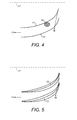
- Figure 4 is showing a schematic sketch of two neighbouring guide means 12 in the axial duct with respect to the machine axis 17 of the exciter 3 according to a first preferred embodiment.
- the generally J-shaped guide means 12 are made of bent metal plates or sheets.
- the flow velocity at the inlet of the axial duct i.e. at the end of the gap between the exciter bell and the static portion, is indicated by a vector arrow 18.
- the speed of the inlet flow is indicated by the length of the arrow 18 and the direction of the flow is indicated by the direction of the arrow 18.
- the flow direction and velocity at the outlet of the axial duct is indicated by a vector arrow 19.
- the speed of the outlet flow is indicated by the length of the arrow 19 and the direction of the flow is indicated by the direction of the arrow 19.
- the flow direction is affected by the rotating exciter and therefore the flow direction is in tangential direction. Due to the high speed rotation of the exciter, the velocity of the flow is relatively high.
- the flow direction has been re-oriented by the guide means 12 into an axial flow direction, i.e. in parallel to the machine axis 17. The flow velocity is relatively low, however the static pressure is increased.
- Figure 5 is showing a schematic sketch of two neighbouring guide means 12 in the axial duct with respect to the machine axis 17 of the exciter according to a second preferred embodiment.
- the guide means 12 are small airfoils in order to improve the performance and in order to eliminate the vortex and losses as shown in figure 4 .
- the flow direction at the inlet of the axial duct is affected by the rotating exciter and therefore the flow direction is in tangential direction (arrow 18). Due to the high speed rotation of the exciter, the velocity of the flow is relatively high.
- the flow direction has been re-oriented by the guide means 12 into an axial flow direction (arrow 19), i.e. in parallel to the machine axis 17. The flow velocity is relatively low, however the static pressure is increased.
- the distance between two neighboring guide means 12 is enlarging towards the downstream position.
- the guide means 12 fulfill a diffuser like function and transform the velocity of the cooling fluid into increased static preasure. This leads to an increased pressure head at the cooler inlet, more pressure head is available for the coolers 7 that can result in an increased efficiency of the coolers.
Landscapes
- Engineering & Computer Science (AREA)
- Power Engineering (AREA)
- Motor Or Generator Cooling System (AREA)
- Permanent Field Magnets Of Synchronous Machinery (AREA)
Abstract
Description
- The present invention relates to a turbo generator comprising a stator and a rotor, having a rotating bell type exciter connected to one end of the rotor and being equipped with at least one cooler.
- Large turbo generators for producing electric energy are designed as three-phase synchron machines comprising a stator and a rotor. One end of the rotor is connected to a turbo machine while the other end is connected to an exciter.
- The European patent application
EP 1 443 639 A1 by the same applicant discloses the electrical function of a rotating exciter for large currents. The rotor has at least two conducting rods essentially parallel to the rotor axis and connected at their first end to a collector ring and connected at their other ends to individual rings via diodes of opposite polarity so that the a.c. current induced in the rods as a result of a static field is converted into a direct field in both rings. - One exciter type known in the art is the
bell type exciter 3 as schematically shown in a partial sectional view infigure 6 . The turbo generator 1 has itsrotor 2 connected to one end to thebell type exciter 3. Theexciter 3 hasmulti-phase windings 4 rotating around astatic portion 8. The exciter current is passed throughdiodes 5 to convert the alternating current into direct current and then fed into the respective rotor windings of the turbo generator 1. The rotating exciter is in other words the opposite of a generator. The windings of thestatic portion 8 of theexciter 3 are fed with direct current and the anchor is therotating bell 10 of theexciter 3 producing alternate current. - The turbo generator 1 including the
exciter 3 is on its lower portion based on theground 6 and confined by a casing 9. Above theexciter 3 and opposite to theground 6, one ormore coolers 7 are arranged within the casing 9 to reduce the temperatures in theexciter 3 and thus increase the efficiency of theexciter 3. - One draw back of the prior art is that in order to enhance the efficiency of the cooler and or to obtain redundance in case of failure of one cooler, the number of coolers need to be increased and/or the coolers need to be enlarged. This conflicts with limitations in space available at the respective site of the power plant. A further draw back of the prior art is the fact that the bell type exciter conveys cooling fluid from the center to its outer circumference. The tangential speed of this cooling fluid flow is quite high and the corresponding kinetic energy is lost.
- Accordingly, the technical problem to be solved by the present invention is to avoid the described draw backs of the prior art and to provide means for increasing the pressure head and improving the efficiency in a bell type exciter.
- This problem is solved by a turbo generator having the features of claim 1. Preferred embodiments of the present invention are described in the dependent claims.
- According to the present invention an axial duct is provided between a cylindrical housing and the outer circumference of the bell type exciter. The housing is arranged concentrically around the rotating exciter. On the inner circumference of the cylindrical housing, several guide means for guiding a fluid are arranged to convert the tangential fluid flow created by the exciter into an axial flow. By converting the tangential flow into an axial flow, a major portion of the dynamic energy of the fluid is transformed into additional pressure head at the cooler, instead of being merely transformed in heat and losses as it is the case in the prior art. Further, by applying the described pressure recovering air guide, also the flow rate may be increased. Thus the drawbacks of the prior art are avoided and the efficiency of the bell type exciter is increased by recovering the dynamic energy of the cooling fluid flow. The simple but effective construction may also be used to upgrade existing bell type exciters in the prescribed way to enhance the efficiency and redundancy of the coolers.
- An advantageous embodiment of the present invention suggests that the guide means are provided as bent sheets or plates. This is a simple version for dynamic pressure recovery by re-orientation of the flow direction.
- Another preferred embodiment suggests that the guide means are provided as guide vanes having an airfoil. This "banana" version of the guide means provides a better performance than the simple guide means made of bent metal sheets and reduces the vortex and losses.
- A further advantageous embodiment of the present invention suggests that the guide means are provided as structural stiffening elements for the housing. Thus the guide means may support the frame in carrying the static parts of the exciter. This leads to a compact design adapted to arrange e.g. two coolers in series and to be able to have 100% performance with one cooler out of service.
- Yet another preferred embodiment suggests that the guide means are arranged on the inner circumference of the cylindrical housing. Thus, the guide means are stationary while the bell is rotating.
- Still another preferred embodiment suggests that the guide means are arranged to direct the cooling fluid through the cooler. According to this embodiment the downstream of the cooling fluid is directed in the portion of the casing, with a higher pressure than the surrounding. This is the inlet side of the cooler.
- Another preferred embodiment suggests that the guide means are J-shaped in axial direction to allow redirecting the tangential flow into axial flow. By this, the guide means are creating defined flow channels over the whole length of the axial duct. This provides advantageous over using guide means only over part of the length of the axial duct.
- Finally, another embodiment of the present invention suggests that the distance between two neighboring guide means is enlarging towards the downstream position. Thus the guide means fulfill a diffuser like function and transform the velocity of the cooling fluid into pressure head between the inlet and outlet of the cooler.
- A more complete appreciation of the invention and many of the attendant advantages thereof will be readily obtained as the same becomes better understood by reference to the following detailed description when considered in connection with the accompanying drawings, wherein:
- FIG. 1
- shows a schematic sectional view of a bell type exciter having an axial duct with guide means according to a preferred embodiment of the present invention;
- FIG. 2
- shows a detail view of
figure 1 ; - FIG. 3
- shows a separate perspective view of the cylindrical housing and the guide means;
- FIG. 4
- shows a schematic view of the guide means according to a first embodiment of the present invention;
- FIG. 5
- shows a schematic view of the guide means according to a second embodiment of the present invention; and
- FIG. 6
- shows a partial sectional view of a turbo generator with bell type exciter according to the prior art.
- Referring now to the drawings, wherein like reference numerals designate identical or corresponding parts throughout the several views, preferred exemplary embodiments of the invention are reproduced in
figures 1 through 5 . The drawings are merely schematic sketches and serve explicatory reasons only. -
Figure 1 shows a schematic sectional view of abell type exciter 3 having anaxial duct 11 with guide means 12 according to a preferred embodiment of the present invention.Figure 2 shows a detail offigure 1 . - The turbo generator has its
rotor 2 connected to one end to thebell type exciter 3. Theexciter 3 has on its inner circumferencemulti-phase windings 4 arranged on top of the lamination 21 and rotating around astatic portion 8. There is a small gap 22 between thewindings 4 and thestatic portion 8 which allows a cooling fluid flow going therethrough. The exciter current is passed throughdiodes 5 to convert the alternating current into direct current and then fed into the respective rotor windings of the turbo generator 1. Theexciter 3 is on its lower portion based on theground 6 and confined by a casing 9. Above theexciter 3 and opposite to theground 6, twocoolers 7 are arranged in series within the casing 9 to reduce the temperatures in theexciter 3 and thus increase the efficiency of theexciter 3. - The
axial duct 11 is created by the outer circumference of thebell 10 and the inner circumference of acylindrical housing 13. Thehousing 13 can also be seen infigure 3 as perspective single part. At the inner circumference of thehousing 13 several J-shaped guide means 12 are arranged. The J-shaped guide means 12 are made of flat metal sheet and are welded onto thehousing 13. Thehousing 13 is held in aframe 14, which is a steel construction. On the upper side, theframe 14 is equipped with a holdingplate 15 for thecoolers 7 and atube guiding plate 16 for the tubing of thecoolers 7. The link to the ground is managed by two end plates. - In
figure 1 andfigure 2 the flow path of the cooling fluid, which is air in the present embodiment, is indicated by black arrows. The cooling air is sucked into thestatic portion 8 of theexciter 3 and streams into the gap between thestatic portion 8 and therotating bell 10. Due to the rotational speed of thebell 10, the air flow gains energy in form of velocity. The air leaving the gap turns outward into radial direction and enters theaxial duct 11 with the J-shaped guide means 12. After leaving theaxial duct 11, the energy of the fluid is converted from velocity into pressure, i.e. the static pressure head between inlet and outlet of the J-shaped guide means 12 is increased improving the efficiency of the exciter. -
Figure 4 is showing a schematic sketch of two neighbouring guide means 12 in the axial duct with respect to themachine axis 17 of theexciter 3 according to a first preferred embodiment. In this embodiment, the generally J-shaped guide means 12 are made of bent metal plates or sheets. The flow velocity at the inlet of the axial duct, i.e. at the end of the gap between the exciter bell and the static portion, is indicated by avector arrow 18. The speed of the inlet flow is indicated by the length of thearrow 18 and the direction of the flow is indicated by the direction of thearrow 18. The flow direction and velocity at the outlet of the axial duct is indicated by avector arrow 19. The speed of the outlet flow is indicated by the length of thearrow 19 and the direction of the flow is indicated by the direction of thearrow 19. - At the inlet of the axial duct the flow direction is affected by the rotating exciter and therefore the flow direction is in tangential direction. Due to the high speed rotation of the exciter, the velocity of the flow is relatively high. At the outlet, the flow direction has been re-oriented by the guide means 12 into an axial flow direction, i.e. in parallel to the
machine axis 17. The flow velocity is relatively low, however the static pressure is increased. - In
figure 4 , an area of vortex andlosses 20 of the flow is marked by a circle. -
Figure 5 is showing a schematic sketch of two neighbouring guide means 12 in the axial duct with respect to themachine axis 17 of the exciter according to a second preferred embodiment. In this embodiment, the guide means 12 are small airfoils in order to improve the performance and in order to eliminate the vortex and losses as shown infigure 4 . Also in the second embodiment the flow direction at the inlet of the axial duct is affected by the rotating exciter and therefore the flow direction is in tangential direction (arrow 18). Due to the high speed rotation of the exciter, the velocity of the flow is relatively high. At the outlet, the flow direction has been re-oriented by the guide means 12 into an axial flow direction (arrow 19), i.e. in parallel to themachine axis 17. The flow velocity is relatively low, however the static pressure is increased. - It might be obvious to the person skilled in the art that numerous modifications and variations of the present invention are possible in the light of the above teaching. It is therefore to be understood that, within the scope of the appended claims, the invention may be practiced otherwise than described herein.
- In both embodiments of
figure 4 and figure 5 , the distance between two neighboring guide means 12 is enlarging towards the downstream position. Thus the guide means 12 fulfill a diffuser like function and transform the velocity of the cooling fluid into increased static preasure. This leads to an increased pressure head at the cooler inlet, more pressure head is available for thecoolers 7 that can result in an increased efficiency of the coolers. -
- 1
- turbo generator
- 2
- rotor
- 3
- exciter
- 4
- multi-phase winding
- 5
- diodes
- 6
- ground
- 7
- cooler
- 8
- static portion
- 9
- casing
- 10
- bell
- 11
- axial duct
- 12
- guide means
- 13
- housing
- 14
- frame
- 15
- holding plate
- 16
- tube guiding plate
- 17
- machine axis
- 18
- inlet flow
- 19
- outlet flow
- 20
- area of vortex and losses
- 21
- lamination
- 22
- gap
Claims (8)
- A turbo generator (1) comprising a stator and a rotor (2), having a rotating bell type exciter (3) connected to one end of the rotor (2) and the exciter (3) being equipped with at least one cooler (7),
characterized in that
an axial duct (11) with guide means (12) is provided between a cylindrical housing (13) and the outer circumference of the bell type exciter (3). - The turbo generator (1) according to claim 1,
characterized in that
the exciter (3) is housed concentrically in the cylindrical housing (13). - The turbo generator (1) according to claim 1 or 2,
characterized in that
the guide means (12) are provided as bent sheets. - The turbo generator (1) according to claim 1 or 2,
characterized in that
the guide means (12) are provided as guide vanes having an airfoil. - The turbo generator (1) according to one of the previous claims,
characterized in that
the guide means (12) are provided as structural stiffening elements for the housing (13). - The turbo generator (1) according to one of the previous claims,
characterized in that
the guide means (12) are arranged on the inner circumference of the cylindrical housing (13). - The turbo generator (1) according to one of the previous claims,
characterized in that
the guide means (12) are J-shaped in axial direction to allow redirecting the tangential flow into axial flow. - The turbo generator (1) according to one of the previous claims,
characterized in that
the distance between two neighboring guide means (12) is enlarging towards the downstream position.
Applications Claiming Priority (1)
| Application Number | Priority Date | Filing Date | Title |
|---|---|---|---|
| US11/688,307 US8742635B2 (en) | 2007-03-20 | 2007-03-20 | Turbo generator with exciter having pressure recovery |
Publications (2)
| Publication Number | Publication Date |
|---|---|
| EP1973218A2 true EP1973218A2 (en) | 2008-09-24 |
| EP1973218A3 EP1973218A3 (en) | 2012-08-15 |
Family
ID=39494551
Family Applications (1)
| Application Number | Title | Priority Date | Filing Date |
|---|---|---|---|
| EP08152521A Ceased EP1973218A3 (en) | 2007-03-20 | 2008-03-10 | Turbo generator with exciter having pressure recovering means |
Country Status (3)
| Country | Link |
|---|---|
| US (1) | US8742635B2 (en) |
| EP (1) | EP1973218A3 (en) |
| CN (1) | CN101272079B (en) |
Families Citing this family (2)
| Publication number | Priority date | Publication date | Assignee | Title |
|---|---|---|---|---|
| DE102011075045A1 (en) | 2011-05-02 | 2012-11-08 | Schaeffler Technologies AG & Co. KG | Cooling jacket and deflection unit for cooling jackets |
| EP2680408B1 (en) * | 2012-06-26 | 2014-12-17 | Etel S. A.. | Frame with integrated cooling for an electric drive |
Citations (1)
| Publication number | Priority date | Publication date | Assignee | Title |
|---|---|---|---|---|
| EP1443639A1 (en) | 2003-02-01 | 2004-08-04 | Alstom Technology Ltd | High current rotating exciter |
Family Cites Families (11)
| Publication number | Priority date | Publication date | Assignee | Title |
|---|---|---|---|---|
| US3643119A (en) * | 1970-11-05 | 1972-02-15 | Gen Electric | Ventilated dynamoelectric machine |
| CH552298A (en) * | 1972-03-10 | 1974-07-31 | Kraftwerk Union Ag | ELECTRIC MACHINE, IN PARTICULAR SYNCHRONOUS GENERATOR, WITH AN EXCITING ARRANGEMENT. |
| JPS5747860U (en) * | 1980-08-28 | 1982-03-17 | ||
| IT1225584B (en) * | 1988-07-26 | 1990-11-22 | Nowax S R L A | DOUBLE COVER ELECTRIC MOTOR CASE WITH FORCED CONVEYOR VENTILATION |
| US4900959A (en) * | 1989-01-06 | 1990-02-13 | Westinghouse Electric Corp. | Insulated outer rotor for brushless exciter |
| ATE118130T1 (en) * | 1991-11-25 | 1995-02-15 | Asea Brown Boveri | GAS COOLED ELECTRIC MACHINE. |
| DE19653839A1 (en) * | 1996-12-21 | 1998-06-25 | Asea Brown Boveri | Rotor of a turbogenerator with direct gas cooling |
| DE19856455A1 (en) * | 1998-12-03 | 2000-06-08 | Asea Brown Boveri | Generator cooling with cooler run-on mixture |
| IT1309310B1 (en) * | 1999-06-30 | 2002-01-22 | Hsd Srl | ELECTRO. |
| GB2399231A (en) * | 2003-03-07 | 2004-09-08 | Alstom | Multi-path cooling of a turbo-generator rotor winding |
| DE102006025487A1 (en) * | 2005-06-07 | 2006-12-14 | Alstom Technology Ltd. | Dynamo-electric machine e.g. generator, has brushless exciter cooled through gaseous cooling medium e.g. air, by using cooling circuit, and one separate fan for circulation of cooling medium in cooling circuit of exciter |
-
2007
- 2007-03-20 US US11/688,307 patent/US8742635B2/en active Active
-
2008
- 2008-03-10 EP EP08152521A patent/EP1973218A3/en not_active Ceased
- 2008-03-19 CN CN2008100860977A patent/CN101272079B/en active Active
Patent Citations (1)
| Publication number | Priority date | Publication date | Assignee | Title |
|---|---|---|---|---|
| EP1443639A1 (en) | 2003-02-01 | 2004-08-04 | Alstom Technology Ltd | High current rotating exciter |
Also Published As
| Publication number | Publication date |
|---|---|
| US20080231125A1 (en) | 2008-09-25 |
| US8742635B2 (en) | 2014-06-03 |
| CN101272079B (en) | 2012-11-28 |
| EP1973218A3 (en) | 2012-08-15 |
| CN101272079A (en) | 2008-09-24 |
Similar Documents
| Publication | Publication Date | Title |
|---|---|---|
| DK1641101T3 (en) | Electric machine with double-sided stator | |
| EP2302766B1 (en) | A hydroelectric turbine with coil cooling | |
| CN1322656C (en) | Sealing apparatus for electrical generator ventilation system | |
| US7839048B2 (en) | Electrical machine with double-sided stator | |
| CN102545405B (en) | Cooling structure for stagewise stator module | |
| US8492951B2 (en) | Segmented stator assembly | |
| EP2651009A2 (en) | Wind turbine with improved cooling | |
| EP3151384B1 (en) | Generator preferably of a wind turbine | |
| CN203491805U (en) | Stator pile used for stator of power generator, and stator of power generator | |
| EP1318299A1 (en) | Bulb turbine-generator unit | |
| EP4102683A1 (en) | Cooling of an electric generator | |
| US8742635B2 (en) | Turbo generator with exciter having pressure recovery | |
| KR102892890B1 (en) | Generators and wind turbines for power generation | |
| KR101213318B1 (en) | Turbine-integrated generator for generating electricity using gas pressure in a gas pipe | |
| EP2713480B1 (en) | Rotor of a permanent magnet generator | |
| US20220021275A1 (en) | Cooling of electrical machines | |
| CN103987962B (en) | Wind Turbine Axial Flux Generator for Converting Wind Power into Electricity | |
| US6787934B2 (en) | Turbine system | |
| US11837925B2 (en) | Ortho-radial induction generator | |
| WO2006039727A1 (en) | Shielded vertical axis turbine | |
| CN218771641U (en) | Generator and wind turbine comprising such a generator | |
| KR102702303B1 (en) | Outer-rotor type permanent magnet synchronous generator | |
| EP3588751B1 (en) | Generator of a wind turbine having an air flow adaptor |
Legal Events
| Date | Code | Title | Description |
|---|---|---|---|
| PUAI | Public reference made under article 153(3) epc to a published international application that has entered the european phase |
Free format text: ORIGINAL CODE: 0009012 |
|
| AK | Designated contracting states |
Kind code of ref document: A2 Designated state(s): AT BE BG CH CY CZ DE DK EE ES FI FR GB GR HR HU IE IS IT LI LT LU LV MC MT NL NO PL PT RO SE SI SK TR |
|
| AX | Request for extension of the european patent |
Extension state: AL BA MK RS |
|
| PUAL | Search report despatched |
Free format text: ORIGINAL CODE: 0009013 |
|
| AK | Designated contracting states |
Kind code of ref document: A3 Designated state(s): AT BE BG CH CY CZ DE DK EE ES FI FR GB GR HR HU IE IS IT LI LT LU LV MC MT NL NO PL PT RO SE SI SK TR |
|
| AX | Request for extension of the european patent |
Extension state: AL BA MK RS |
|
| RIC1 | Information provided on ipc code assigned before grant |
Ipc: H02K 9/06 20060101ALI20120710BHEP Ipc: H02K 5/20 20060101AFI20120710BHEP Ipc: H02K 9/18 20060101ALI20120710BHEP Ipc: H02K 19/38 20060101ALI20120710BHEP |
|
| 17P | Request for examination filed |
Effective date: 20130211 |
|
| 17Q | First examination report despatched |
Effective date: 20130312 |
|
| AKX | Designation fees paid |
Designated state(s): AT BE BG CH CY CZ DE DK EE ES FI FR GB GR HR HU IE IS IT LI LT LU LV MC MT NL NO PL PT RO SE SI SK TR |
|
| RAP1 | Party data changed (applicant data changed or rights of an application transferred) |
Owner name: GENERAL ELECTRIC TECHNOLOGY GMBH |
|
| STAA | Information on the status of an ep patent application or granted ep patent |
Free format text: STATUS: THE APPLICATION HAS BEEN REFUSED |
|
| 18R | Application refused |
Effective date: 20180920 |