EP1973184A2 - Membrane Electrode Assembly and Method of Manufacturing Same - Google Patents
Membrane Electrode Assembly and Method of Manufacturing Same Download PDFInfo
- Publication number
- EP1973184A2 EP1973184A2 EP20080152826 EP08152826A EP1973184A2 EP 1973184 A2 EP1973184 A2 EP 1973184A2 EP 20080152826 EP20080152826 EP 20080152826 EP 08152826 A EP08152826 A EP 08152826A EP 1973184 A2 EP1973184 A2 EP 1973184A2
- Authority
- EP
- European Patent Office
- Prior art keywords
- gas diffusion
- diffusion layer
- electrode assembly
- gasket
- membrane electrode
- Prior art date
- Legal status (The legal status is an assumption and is not a legal conclusion. Google has not performed a legal analysis and makes no representation as to the accuracy of the status listed.)
- Granted
Links
- 239000012528 membrane Substances 0.000 title claims abstract description 80
- 238000004519 manufacturing process Methods 0.000 title claims abstract description 52
- 238000009792 diffusion process Methods 0.000 claims abstract description 104
- 239000000463 material Substances 0.000 claims abstract description 73
- 230000003197 catalytic effect Effects 0.000 claims abstract description 70
- 229920005989 resin Polymers 0.000 claims abstract description 35
- 239000011347 resin Substances 0.000 claims abstract description 35
- 239000003792 electrolyte Substances 0.000 claims abstract description 30
- 238000000465 moulding Methods 0.000 claims abstract description 11
- 238000001816 cooling Methods 0.000 claims description 35
- 238000010438 heat treatment Methods 0.000 claims description 33
- 238000002347 injection Methods 0.000 claims description 14
- 239000007924 injection Substances 0.000 claims description 14
- 238000000034 method Methods 0.000 claims description 14
- 238000000748 compression moulding Methods 0.000 claims description 12
- 230000002093 peripheral effect Effects 0.000 claims description 10
- 238000001746 injection moulding Methods 0.000 claims description 9
- 239000007789 gas Substances 0.000 description 94
- 230000036961 partial effect Effects 0.000 description 15
- 239000000446 fuel Substances 0.000 description 6
- -1 polyethylene naphthalate Polymers 0.000 description 6
- 239000000843 powder Substances 0.000 description 6
- 238000003825 pressing Methods 0.000 description 6
- 239000002826 coolant Substances 0.000 description 5
- 230000000717 retained effect Effects 0.000 description 5
- 239000012809 cooling fluid Substances 0.000 description 4
- 230000006866 deterioration Effects 0.000 description 3
- 238000006073 displacement reaction Methods 0.000 description 3
- 239000012530 fluid Substances 0.000 description 3
- 238000005259 measurement Methods 0.000 description 3
- 238000012986 modification Methods 0.000 description 3
- 230000004048 modification Effects 0.000 description 3
- 239000005518 polymer electrolyte Substances 0.000 description 3
- 238000012545 processing Methods 0.000 description 3
- 230000002829 reductive effect Effects 0.000 description 3
- 239000007787 solid Substances 0.000 description 3
- 229920001187 thermosetting polymer Polymers 0.000 description 3
- 238000012546 transfer Methods 0.000 description 3
- 239000004698 Polyethylene Substances 0.000 description 2
- 239000004734 Polyphenylene sulfide Substances 0.000 description 2
- 239000004743 Polypropylene Substances 0.000 description 2
- 239000004793 Polystyrene Substances 0.000 description 2
- XECAHXYUAAWDEL-UHFFFAOYSA-N acrylonitrile butadiene styrene Chemical compound C=CC=C.C=CC#N.C=CC1=CC=CC=C1 XECAHXYUAAWDEL-UHFFFAOYSA-N 0.000 description 2
- 229920000122 acrylonitrile butadiene styrene Polymers 0.000 description 2
- 239000004676 acrylonitrile butadiene styrene Substances 0.000 description 2
- 238000006243 chemical reaction Methods 0.000 description 2
- 230000003247 decreasing effect Effects 0.000 description 2
- 238000002474 experimental method Methods 0.000 description 2
- 230000006870 function Effects 0.000 description 2
- 239000012535 impurity Substances 0.000 description 2
- 230000000670 limiting effect Effects 0.000 description 2
- 229920003207 poly(ethylene-2,6-naphthalate) Polymers 0.000 description 2
- 229920001707 polybutylene terephthalate Polymers 0.000 description 2
- 239000004417 polycarbonate Substances 0.000 description 2
- 239000011112 polyethylene naphthalate Substances 0.000 description 2
- 229920000139 polyethylene terephthalate Polymers 0.000 description 2
- 239000005020 polyethylene terephthalate Substances 0.000 description 2
- 229920006324 polyoxymethylene Polymers 0.000 description 2
- 229920000069 polyphenylene sulfide Polymers 0.000 description 2
- 239000002002 slurry Substances 0.000 description 2
- LSNNMFCWUKXFEE-UHFFFAOYSA-M Bisulfite Chemical compound OS([O-])=O LSNNMFCWUKXFEE-UHFFFAOYSA-M 0.000 description 1
- 239000004593 Epoxy Substances 0.000 description 1
- 229920000557 Nafion® Polymers 0.000 description 1
- ISWSIDIOOBJBQZ-UHFFFAOYSA-N Phenol Chemical compound OC1=CC=CC=C1 ISWSIDIOOBJBQZ-UHFFFAOYSA-N 0.000 description 1
- 229930182556 Polyacetal Natural products 0.000 description 1
- 239000004952 Polyamide Substances 0.000 description 1
- 238000013459 approach Methods 0.000 description 1
- 230000009286 beneficial effect Effects 0.000 description 1
- 230000015572 biosynthetic process Effects 0.000 description 1
- 238000004891 communication Methods 0.000 description 1
- 230000000694 effects Effects 0.000 description 1
- 238000005516 engineering process Methods 0.000 description 1
- 239000002737 fuel gas Substances 0.000 description 1
- 239000007791 liquid phase Substances 0.000 description 1
- 239000000203 mixture Substances 0.000 description 1
- 230000000149 penetrating effect Effects 0.000 description 1
- 229920003229 poly(methyl methacrylate) Polymers 0.000 description 1
- 229920002647 polyamide Polymers 0.000 description 1
- 229920000515 polycarbonate Polymers 0.000 description 1
- 229920000573 polyethylene Polymers 0.000 description 1
- 229920005597 polymer membrane Polymers 0.000 description 1
- 239000004926 polymethyl methacrylate Substances 0.000 description 1
- 229920001155 polypropylene Polymers 0.000 description 1
- 229920002223 polystyrene Polymers 0.000 description 1
- 230000000452 restraining effect Effects 0.000 description 1
- 238000007789 sealing Methods 0.000 description 1
- 239000000725 suspension Substances 0.000 description 1
- TXEYQDLBPFQVAA-UHFFFAOYSA-N tetrafluoromethane Chemical compound FC(F)(F)F TXEYQDLBPFQVAA-UHFFFAOYSA-N 0.000 description 1
- 229920005992 thermoplastic resin Polymers 0.000 description 1
- 229920006305 unsaturated polyester Polymers 0.000 description 1
- 229920003186 unsaturated thermoplastic elastomer Polymers 0.000 description 1
- XLYOFNOQVPJJNP-UHFFFAOYSA-N water Substances O XLYOFNOQVPJJNP-UHFFFAOYSA-N 0.000 description 1
Images










Classifications
-
- H—ELECTRICITY
- H01—ELECTRIC ELEMENTS
- H01M—PROCESSES OR MEANS, e.g. BATTERIES, FOR THE DIRECT CONVERSION OF CHEMICAL ENERGY INTO ELECTRICAL ENERGY
- H01M8/00—Fuel cells; Manufacture thereof
- H01M8/02—Details
- H01M8/0271—Sealing or supporting means around electrodes, matrices or membranes
- H01M8/0286—Processes for forming seals
-
- H—ELECTRICITY
- H01—ELECTRIC ELEMENTS
- H01M—PROCESSES OR MEANS, e.g. BATTERIES, FOR THE DIRECT CONVERSION OF CHEMICAL ENERGY INTO ELECTRICAL ENERGY
- H01M8/00—Fuel cells; Manufacture thereof
- H01M8/02—Details
- H01M8/0202—Collectors; Separators, e.g. bipolar separators; Interconnectors
- H01M8/0267—Collectors; Separators, e.g. bipolar separators; Interconnectors having heating or cooling means, e.g. heaters or coolant flow channels
-
- H—ELECTRICITY
- H01—ELECTRIC ELEMENTS
- H01M—PROCESSES OR MEANS, e.g. BATTERIES, FOR THE DIRECT CONVERSION OF CHEMICAL ENERGY INTO ELECTRICAL ENERGY
- H01M8/00—Fuel cells; Manufacture thereof
- H01M8/02—Details
- H01M8/0271—Sealing or supporting means around electrodes, matrices or membranes
- H01M8/0273—Sealing or supporting means around electrodes, matrices or membranes with sealing or supporting means in the form of a frame
-
- H—ELECTRICITY
- H01—ELECTRIC ELEMENTS
- H01M—PROCESSES OR MEANS, e.g. BATTERIES, FOR THE DIRECT CONVERSION OF CHEMICAL ENERGY INTO ELECTRICAL ENERGY
- H01M8/00—Fuel cells; Manufacture thereof
- H01M8/10—Fuel cells with solid electrolytes
- H01M2008/1095—Fuel cells with polymeric electrolytes
-
- H—ELECTRICITY
- H01—ELECTRIC ELEMENTS
- H01M—PROCESSES OR MEANS, e.g. BATTERIES, FOR THE DIRECT CONVERSION OF CHEMICAL ENERGY INTO ELECTRICAL ENERGY
- H01M8/00—Fuel cells; Manufacture thereof
- H01M8/02—Details
- H01M8/0271—Sealing or supporting means around electrodes, matrices or membranes
- H01M8/028—Sealing means characterised by their material
- H01M8/0284—Organic resins; Organic polymers
-
- Y—GENERAL TAGGING OF NEW TECHNOLOGICAL DEVELOPMENTS; GENERAL TAGGING OF CROSS-SECTIONAL TECHNOLOGIES SPANNING OVER SEVERAL SECTIONS OF THE IPC; TECHNICAL SUBJECTS COVERED BY FORMER USPC CROSS-REFERENCE ART COLLECTIONS [XRACs] AND DIGESTS
- Y02—TECHNOLOGIES OR APPLICATIONS FOR MITIGATION OR ADAPTATION AGAINST CLIMATE CHANGE
- Y02E—REDUCTION OF GREENHOUSE GAS [GHG] EMISSIONS, RELATED TO ENERGY GENERATION, TRANSMISSION OR DISTRIBUTION
- Y02E60/00—Enabling technologies; Technologies with a potential or indirect contribution to GHG emissions mitigation
- Y02E60/30—Hydrogen technology
- Y02E60/50—Fuel cells
-
- Y—GENERAL TAGGING OF NEW TECHNOLOGICAL DEVELOPMENTS; GENERAL TAGGING OF CROSS-SECTIONAL TECHNOLOGIES SPANNING OVER SEVERAL SECTIONS OF THE IPC; TECHNICAL SUBJECTS COVERED BY FORMER USPC CROSS-REFERENCE ART COLLECTIONS [XRACs] AND DIGESTS
- Y02—TECHNOLOGIES OR APPLICATIONS FOR MITIGATION OR ADAPTATION AGAINST CLIMATE CHANGE
- Y02P—CLIMATE CHANGE MITIGATION TECHNOLOGIES IN THE PRODUCTION OR PROCESSING OF GOODS
- Y02P70/00—Climate change mitigation technologies in the production process for final industrial or consumer products
- Y02P70/50—Manufacturing or production processes characterised by the final manufactured product
Definitions
- the invention relates to a membrane electrode assembly and a method of manufacturing the same.
- the invention also relates to an apparatus for the manufacture of the membrane electrode assembly. Aspects of the invention relate to an assembly, to a method, to an apparatus and to a vehicle.
- a fuel cell is formed by stacking a membrane electrode assembly that forms a catalytic layer and a gas diffusion layer on each of the surfaces of an electrolyte membrane and interposing a separator therebetween.
- WO 01/017048 discloses an electrolyte membrane exposed to the catalytic layer.
- the gas diffusion layer is not formed at an outer peripheral portion of the membrane electrode assembly.
- a gasket formed with a resin material for providing sealing between the outer peripheral portion and the separator is applied thereto.
- An optimum thickness of such a gasket is determined based on a thickness of the gas diffusion layer. Thus, when there is a change in size of the gas diffusion layer, it is necessary to prepare various types of gaskets with different thicknesses to accommodate the changing thickness of the gas diffusion layer.
- gaskets of varying thicknesses are limited, and it is possible that a gasket having the optimum thickness for a gas diffusion layer cannot be used.
- the gasket is not thick enough, the gas diffusing performance and the drainage performance deteriorate since the gas diffusion layer is excessively pressed and crushed.
- the power generating efficiency deteriorates since the electrical resistance of the gas diffusion layer increases.
- a method of manufacturing a membrane electrode assembly having both a catalytic layer and a gas diffusion layer on opposing surfaces of an electrolyte membrane comprising measuring thicknesses of the catalytic layer and the gas diffusion layer, determining a thickness of a gasket portion according to the thicknesses of the catalytic layer and the gas diffusion layer and molding the gasket portion having the determined thickness around at least a portion of the catalytic layer and the gas diffusion layer.
- the method may comprise compressing the catalytic layer and the gas diffusion layer until a thickness of the catalytic layer and the gas diffusion layer is approximately equal to the thickness of the gasket portion.
- the catalytic layer and the gas diffusion layer are compressed with a separator.
- the gasket portion is a resin material. In an embodiment, the gasket portion is molded by injection-molding or injection compression-molding.
- molding the gasket portion comprises forming a molding space with a mold cast and injecting the resin material into the molding space through a gate in the mold cast, wherein an inclined surface is formed at an outer peripheral edge portion of the gasket portion at a region of the gate.
- a manufacturing apparatus for use with a membrane electrode assembly having both a catalytic layer and a gas diffusion layer on opposing surfaces of an electrolyte membrane, the apparatus comprising a mold cast including a gripping portion configured to grip an edge portion of the catalytic and the gas diffusion layers, a measuring portion configured to measure thicknesses of the catalytic layer and the gas diffusion layer, a moveable block operable to move forward and backward against the electrolyte membrane along an inner side surface of the gripping portion, the moveable block having a side opposite the gripping portion and adjacent to an outer peripheral end of the gas diffusion layer and a control portion configured to control the forward-backward movement of the moveable block according to the thicknesses of the catalytic layer and the gas diffusion layer.
- the gripping portion has an inclined surface
- the apparatus further comprising a gate through which a resin material is injected, the gate positioned at the inclined surface of the gripping portion.
- the gate is a pin gate or a film gate.
- the moveable block has a heating portion configured to heat the moveable block.
- the moveable block has a block cooling portion configured to cool the moveable block.
- the mold cast has a mold cast cooling portion configured to cool a region of the mold cast adjacent to the gas diffusion layer.
- One such method comprises measuring thicknesses of the catalytic layer and the gas diffusion layer, determining a thickness of a gasket portion according to the thicknesses of the catalytic layer and the gas diffusion layer and molding the gasket portion having the determined thickness around the catalytic layer and the gas diffusion layer on the electrolyte membrane.
- One embodiment of the manufacturing apparatus comprises a mold cast including a gripping portion configured to grip an edge portion of the catalytic and the gas diffusion layers, a measuring portion configured to measure thicknesses of the catalytic layer and the gas diffusion layer, a moveable block operable to move forward and backward against the electrolyte membrane along an inner side surface of the gripping portion, the moveable block having a side opposite the gripping portion and adjacent to an outer peripheral end of the gas diffusion layer, and a control portion configured to control the forward-backward movement of the moveable block according to the thicknesses of the catalytic layer and the gas diffusion layer.
- a membrane electrode assembly 1 in accordance with a first embodiment has a stacking structure wherein a solid polymer electrolyte membrane 2 is inserted between an anode 3 and a cathode 4.
- the solid polymer electrolyte membrane 2 may include a perfluorocarbon polymer membrane having a sulfonic acid base. An example of this is Nafion 1128®.
- the anode 3 comprises a first catalytic layer 5A and a first gas diffusion layer 6A, while the cathode 4 comprises a second catalytic layer 5B and a second gas diffusion layer 6B.
- a first gasket portion 8A and a second gasket portion 8B formed with resin materials are integrally installed on each side of the electrolyte membrane 2 and around the edges of the catalytic layers 5A and 5B and the gas diffusion layers 6A and 6B. Thicknesses H1 and H2 of the first and second gasket portions 8A and 8B, respectively, are formed such that the surfaces of gasket portions 8A and 8B opposite the electrolyte membrane 2 do not extend as high as the surfaces of the first and second gas diffusion layers 6A and 6B.
- the first and second gas diffusion layers 6A and 6B extend higher than the first and second gasket portions 8A and 8B by step heights H3 and H4, respectively.
- Outer peripheral edge portions of the gasket portions 8A and 8B are inclined to form inclined surfaces 10A and 10B.
- the resin materials used for the gasket portions 8A and 8B may include PEN (polyethylene naphthalate), PET (polyethylene terephthalate), PBT (polybutylene terephthalate), PA (polyamide), PP (polypropylene), POM (polyacetal), PC (polycarbonate), PE (polyethylene), PS (polystyrene), ABS (acrylonitrile butadiene styrene), PMMA (acryl), PPS (polyphenylene sulfide), epoxy, phenol, unsaturated polyester and thermoplastic elastomer as non-limiting examples.
- PEN polyethylene naphthalate
- PET polyethylene terephthalate
- PBT polybutylene terephthalate
- PA polyamide
- PP polypropylene
- POM polyacetal
- PC polycarbonate
- PE polyethylene
- PS polystyrene
- ABS acrylonitrile butadiene styrene
- PMMA
- the membrane electrode assembly 1 overlaps with a separator 9 when constituting a fuel cell.
- the gasket portions 8A and 8b are adhered to the separator 9, thereby functioning to prevent leakage of fuel gas or coolant.
- the gas diffusion layers 6A and 6B are formed higher than the gasket portions 8A and 8B, they are compressed until their surfaces are planar with the surfaces of the gasket portions 8A and 8B. If the gas diffusion layers 6A and 6B are excessively pressed and crushed, then the gas diffusing performance and the drainage performance deteriorate. Further, if the gas diffusion layers 6A and 6B are not compressed enough, then the electrical resistance increases.
- the thicknesses H1 and H2 of the gasket portions 8A and 8B are manufactured to optimize the gas diffusing performance, the drainage performance and the electrical resistance.
- the thicknesses H1 and H2 of the gasket portions 8A and 8B are established such that the step heights H3 and H4 become, for example, predetermined values within a range of 30 to 200 ⁇ m.
- the invention is not specifically limited to values within such a range.
- the manufacturing apparatus of the membrane electrode assembly in accordance with the first embodiment comprises an apparatus for installing a pre-assembly 21 as illustrated in FIGS. 4 and 5 , which forms the catalytic layers 5A and 5B and the gas diffusion layers 6A and 6B on both surfaces of the electrolyte membrane 2.
- the apparatus also integrally injection-molds or injection thermal compression-molds the gasket portions 8A and 8B by injecting the resin materials to the electrolyte membrane 2.
- the pre-assembly 21 has a plurality of through-holes 22 along the edge portion of the electrolyte membrane 2.
- the manufacturing apparatus 20 of the membrane electrode assembly comprises a pair of first and second mold casts 25A and 25B, respectively including a first moveable block 24A and a second moveable block 24B therein.
- the manufacturing apparatus 20 further comprises a pressing device (not shown) for pressing the first and second mold casts 25A and 25B, a first driving portion 26A and a second driving portion 26B for driving the first and second moveable blocks 24A and 24B, a first control portion 28A and a second control portion 28B (shown in FIG.
- first and second driving portions 26A and 26B for controlling the first and second driving portions 26A and 26B, a first measuring portion 29A for measuring a total thickness of the first catalytic layer 5A and the first gas diffusion layer 6A, and a second measuring portion 29B for measuring a total thickness of the second catalytic layer 5B and the second gas diffusion layer 6B.
- the first and second measuring portions 29A and 29B are arranged on the first and second mold casts 25A and 25B, respectively.
- the first mold cast 25A and the second mold cast 25B can be relatively closely spaced by the pressing device.
- a first gripping portion 31 A and a second gripping portion 31 B for inserting and gripping the edge portion of the electrolyte membrane 2 are formed on outer peripheries of each opposite surface of the first and second mold casts 25A, 25B.
- a plurality of projections 32 are formed on a surface of the second gripping portion 31 B opposite to the first gripping portion 31A in a circumferential direction, while a fitting portion 33 is formed on a surface of the first gripping portion 31A opposite to the second gripping portion 31 B. The projections 32 are matingly received by the fitting portions 33.
- gripping portion inclined surfaces 35A and 35B are formed. Also, one or more gates 36A and 36B for injecting the resin materials are installed on the gripping portion inclined surfaces 35A and 35B.
- the gates 36A and 36B are formed of a pin gate or a film gate having a width in a shape of a film.
- the gates 36A and 36B are in communication with supply pipes 37A and 37B connected to the mold casts 25A and 25B from the outside.
- the resin materials are supplied from the supply pipes 37A and 37B.
- a first block receiving portion 39A and a second block receiving portion 39B are formed along the inner side surfaces of the gripping portions 31A and 31 B.
- the first moveable block 24A is received in the first block receiving portion 39A
- the second moveable block 24B is received in the second block receiving portion 39B.
- the first moveable block 24A and the second moveable block 24B are installed by being divided into four blocks in a circumferential direction.
- the four blocks are provided as a non-limiting example, and the number of divisions is not limited. Further, the blocks need not be divided.
- the first moveable block 24A is configured to be forwardly and backwardly moveable toward a direction of the installed pre-assembly 21 by the first driving portion 26A having a servo motor, cylinder, or the like.
- the second moveable block 24B is also configured to be forwardly and backwardly moveable toward a direction of the installed pre-assembly 21 by the second driving portion 26B having a servo motor, cylinder, or the like.
- a first opposite surface and a second opposite surface opposed to the pre-assembly 21 are formed.
- Opposite surface inner side portions 41A and 41 B in opposite side (inner side) of the gripping portions 31 A and 31 B of each opposite surface are positioned opposite to outer peripheral ends of the gas diffusion layers 6A and 6B.
- the forward and backward movements of the first and second moveable blocks 24A and 24B are controlled by the first and second control portions 28A and 28B, respectively.
- the first control portion 28A and the second control portion 28B are generally implemented by software stored on, for example, memory of a computer and operated by a central processing unit (CPU).
- CPU central processing unit
- first measuring portions 29A for measuring the thickness of the first catalytic layer 5A and the first gas diffusion layer 6A are installed at a position opposite to the first gas diffusion layer 6A of the pre-assembly 21.
- the first measuring portion 29A is, for example, a pressure gauge wherein the thicknesses of the first catalytic layer 5A and the first gas diffusion layer 6A are converted from a pressure when contacting the first gas diffusion layer 6A with a predetermined protruding amount.
- the first measuring portion 29A for example, may include a displacement gauge.
- Each first measuring portion 29A is connected to the first control portion 28A, and a measuring signal from the first measuring portion 29A is input to the first control portion 28A.
- the first control portion 28A calculates an average of the thicknesses of the first catalytic layer 5A and the first gas diffusion layer 6A based on signals from a plurality of the first measuring portions 29A. According to the result of such a measurement, the first moveable block 24A can be forwardly and backwardly moved.
- one or more second measuring portions 29B for measuring the thickness of the second catalytic layer 5B and the second gas diffusion layer 6B are installed at a position opposite to the second gas diffusion layer 6B of the pre-assembly 21.
- the second measuring portion 29B is, for example, a pressure gauge wherein the thicknesses of the second catalytic layer 5B and the second gas diffusion layer 6B are converted from a pressure when contacting the second gas diffusion layer 6B with a predetermined protruding amount.
- the second measuring portion 29B may include a displacement gauge.
- Each second measuring portion 29B is connected to the second control portion 28B, and a measuring signal from the second measuring portion 29B is input to the second control portion 28B.
- the second control portion 28B calculates an average of the thicknesses of the second catalytic layer 5B and the second gas diffusion layer 6B based on signals from a plurality of the second measuring portions 29B. According to a result of such a measurement, the second moveable block 24B can be forwardly and backwardly moved.
- the pre-assembly 21 is installed in the second mold cast 25B.
- the projection 32 of the second mold cast 25B is inserted through the through hole 22 of the pre-assembly 21.
- the pre-assembly 21 can be securely retained and supported at the time of the injection molding operation.
- the first mold cast 25A and the second mold cast 25B are closed by the pressing device, thereby being mold-clamped.
- the electrolyte membrane 2 of the pre-assembly 21 is inserted and gripped between the first gripping portion 31 A and the second gripping portion 31 B.
- the projection 32 of the second gripping portion 31 B is fitted into the fitting portion 33 of the first gripping portion 31A.
- the opposite surface inner side portions 41A and 41 B press the first and second gas diffusion layers 6A and 6B. Consequently, a first injection space 42A and a second injection space 42B are formed on an outer side of the gas diffusion layers 6A and 6B and the catalytic layers 5A and 5B of the electrolyte membrane 2.
- the first moveable block 24A is forwardly and backwardly moved by controlling the first driving portion 26A by a predetermined amount according to such a calculated result.
- the pressure value measured by the first measuring portion 29A and the average of the thicknesses of the first catalytic layer 5A and the first gas diffusion layer 6A are stored and calculated by previously measuring a relationship between the pressure value and the thickness by an experiment.
- the measurement can be performed by using a displacement gauge or laser measuring instrument. However, at this time, it is not necessary to convert the thickness from the pressure by a previous experiment. As described above, since known techniques can be appropriately applied to measure the thickness, the details thereof are omitted herein.
- the second moveable block 24B is forwardly and backwardly moved by controlling the second driving portion 26B by a predetermined amount according to such a calculated result.
- the thicknesses of the catalytic layers 5A and 5B are very thin, being within a range of 3 to 20 ⁇ m, and variation thereof is very small.
- the thicknesses of the gas diffusion layers 6A and 6B are comparatively thick, being within a range of 200 to 600 ⁇ m, and variation thereof is large.
- operating performance may be deteriorated as this is not as accurate as the present embodiment.
- the resin materials are injected from the supply pipes 37A and 37B through the gates 36A and 36B to the first injection space 42A and the second injection space 42B.
- the membrane electrode assembly 1 is extracted wherein the first gasket portion 8A and the second gasket portion 8B are molded by releasing the first mold cast 25A and the second mold cast 25B after the resin material is injected in a fused state and the resin material is hardened due to a drop in temperature.
- the membrane electrode assembly 1 is extracted wherein the first gasket portion 8A and the second gasket portion 8B are molded by releasing the first mold cast 25A and the second mold cast 25B after the resin material in a liquid phase is injected.
- the resin material is then hardened by heating at a temperature higher than a hardening temperature by a heater (not shown) installed in the first mold cast 25A and the second mold cast 25B.
- the membrane electrode assembly 1 manufactured as above since the resin material is injected from the inclined surfaces 10A and 10B, resin remaining in the gates 36A and 36B and protruding in an outer peripheral direction after the gates are removed can be prevented from contacting the separator 9. Further, adhesion with the separator 9 can be favorably maintained when constituting the fuel cell.
- the catalytic layers 5A and 5B and the gasket portions 8A and 8B can be molded to have optimum thicknesses corresponding to the gas diffusion layers 6A and 6B.
- Such an optimum thickness is, for example, established such that the thicknesses H1 and H2 of the gaskets are respectively determined as 80% of the thicknesses of the catalytic layer 5A and the gas diffusion layer 6A and the thicknesses of the catalytic layer 5B and the gas diffusion layer 6B. Further, such a ratio can be appropriately varied according to the types of the gas diffusion layers.
- the resin materials can be restrained from penetrating into the gas diffusion layers 6A and 6B. Moreover, the deterioration of the gas diffusing performance of the gas diffusion layers 6A and 6B and the drainage performance can be restrained.
- the thicknesses H1 and H2 of the gasket portions 8A and 8B can be established by measuring the thicknesses of the catalytic layer 5A and the gas diffusion layer 6A, as well as the catalytic layer 5B and the gas diffusion layer 6B, by the measuring portions 29A and 29B, even when the thicknesses of the gas diffusion layers 6A and 6B are changed.
- the step heights H3 and H4 with the optimum value.
- the deterioration of the power generating efficiency of the fuel cell can be suppressed by restraining the deterioration of the gas diffusing performance and the drainage performance of the gas diffusion layers 6A and 6B.
- step heights H3 and H4 can be established separately, even when the materials of an anode side and a cathode side of the gas diffusion layers 6A and 6B are different, each side can be maintained with the optimum step heights H3 and H4.
- the gasket portions 8A and 8B can be integrally molded with an optimum size, making it unnecessary to have various types of gaskets prepared, thereby reducing costs.
- the membrane electrode assembly 1 of this embodiment since the gasket portions 8A and 8B are integrally molded, the number of components can be reduced, and position precision can be improved. Further, when the gasket is installed as a separate member, there may be a concern that bubbles or impurities are intermixed between the gasket and the electrolyte membrane. However, according to the manufacturing method disclosed herein, the likelihood of intermixing a bubble or impurities is very low. Because it is not necessary to bond the gasket as a separate member when assembling the fuel cell, the number of operations can be reduced.
- a manufacturing apparatus 50 of a membrane electrode assembly and a manufacturing method in accordance with a second embodiment differ from the manufacturing apparatus 20 and the manufacturing method in accordance with the first embodiment.
- the gasket portions 8A and 8B are compression-molded in the second embodiment, whereas the gasket portions 8A and 8B are injection-molded or injection thermal compression-molded in the first embodiment.
- the membrane electrode assembly 1 manufactured in the second embodiment has the same structure of the membrane electrode assembly 1 in the first embodiment.
- the manufacturing apparatus 50 of the membrane electrode assembly in accordance with the second embodiment comprises an apparatus for installing the pre-assembly 21 as in FIGS. 4 and 5 , which forms the catalytic layers 5A and 5B and the gas diffusion layers 6A and 6B on both surfaces of the electrolyte membrane 2.
- the apparatus also integrally compression-molds the gasket portions 8A and 8B on the electrolyte membrane 2.
- the manufacturing apparatus 50 comprises a pair of a first mold cast 52A and a second mold cast 52B, respectively including a first moveable block 51A and a second moveable block 51 B therein.
- the first moveable block 51A comprises a first heating portion 53, which is used to heat the first moveable block 51 A.
- the first heating portion 53 has is elongated along a length direction of the first moveable block 51A.
- a heat transfer heater unit is advantageously used for the first heating portion 53 in the present embodiment, although other structures (e.g., a structure of using a high frequency heater or leaking a high temperature fluid) may be applied. Further, since the heat transfer heater unit is a known device, the detailed explanations thereof is omitted herein.
- the first heating portion 53 is connected to an external power source unit (not shown), and a temperature of the first heating portion 53 can be arbitrarily established by controlling the power source unit.
- the second moveable block 51 B comprises a second heating portion 54 for heating the second moveable block 51 B and a block cooling portion 55 for cooling the second moveable block 51 B.
- the second heating portion 54 is elongated along a length direction of the second moveable block 51 B.
- a high frequency heater unit capable of rapid heating is beneficial as the second heating portion 54 in the present embodiment, although other structures (e.g., a structure of using a heat transfer heater or leaking a high temperature fluid) may be applied. Further, since the high frequency heater unit is a known device, the detailed explanations thereof are omitted herein.
- the second heating portion 54 is connected to an external power source unit (not shown), and a temperature of the second heating portion 54 can be arbitrarily established by controlling the power source unit.
- the block cooling portion 55 is elongated along a length direction of the second moveable block 51 B.
- a Peltier system cooling element is advantgeous for the block cooling portion 55 in the present embodiment, although other structures (e.g., a structure of leaking a low temperature fluid) may be applied.
- the block cooling portion 55 is connected to an external power source unit (not shown), and a temperature of the block cooling portion 55 can be arbitrarily established by controlling the power source unit.
- a first mold cast cooling portion 57A is installed in a first center portion 56A of the first mold cast 52A surrounded by the first moveable block 51A. Further, in a second center portion 56B of the second mold cast 52B surrounded by the second moveable block 52B, a second mold cast cooling portion 57B is installed.
- the first mold cast cooling portion 57A and the second mold cast cooling portion 57B comprise a first cooling flow path 58A and a second cooling flow path 58B, respectively.
- a cooling medium e.g., coolant water
- the first cooling flow path 58A is formed as a plurality of flow paths along a length direction of each first moveable block 51 A so as to surround four sides of the first center portion 56A.
- the second cooling flow path 58B is also formed as a plurality of flow paths along a length direction of each second moveable block 51 B so as to surround four sides of the second center portion 56B. Shapes of the flow paths are not specifically limited but may include a formation of a single path rather than a plurality of paths bent in a rectangular shape along length directions of the first and second moveable block 51A and 51 B.
- the first center portion 56A and the second center portion 56B of the first mold cast 52A and the second mold cast 52B are cooled by supplying the cooling medium from the cooling fluid supply source to the first and second cooling flow paths 58A and 58B.
- the first moveable block 51A is heated by operating the first heating portion 53. Heating of the first moveable block 51A while cooling the first center portion 56A and the second center portion 56B is maintained all the time during a processing cycle.
- the second moveable block 51 B is cooled by operating the block cooling portion 55.
- a second resin filling material 60B is loaded on the second moveable block 51 B of the second mold cast 52B.
- the pre-assembly 21 is installed on the second mold cast 52B.
- the projection 32 of the second mold cast 52B is inserted through the through-hole 22 of the pre-assembly 21, the pre-assembly 21 can be securely retained and supported at the time of a compression-molding operation, which is explained below.
- a first resin filling material 60A is loaded on a position corresponding to the first moveable block 51 A of the pre-assembly 21.
- the first and second filling materials 60A and 60B described above are materials in the shape of a sheet mainly consisting of thermosetting resins. For example, such materials can be input in any position by suctioning with a suction pad in the shape of a sponge.
- the first and second filling materials 60A and 60B may include a powder material, a semi-hardened material obtained by pre-heating the powder material or a gel material (i.e., slurry material). In the case of the powder or gel, the first and second filling materials 60A and 60B can be injected on any position by being discharged from a nozzle.
- first and second filling materials 60A and 60B are formed in an annular shape surrounding an outer periphery of the gas diffusion layers 6A and 6B, although the first and second filling materials 60A and 60B may be installed by being divided into a plurality of pieces.
- the first mold cast 52A and the second mold cast 52B are closed by the pressing means to thereby become mold-clamped, while being rapidly heated by stopping operation of the block cooling portion 55 of the second moveable block 51 B and operating the second heating portion 54.
- the electrolyte membrane 2 of the pre-assembly 21 is inserted and gripped between the first gripping portion 31A and the second gripping portion 31 B.
- the projection 32 of the second gripping portion 31 B is fitted in the fitting portion 33 of the first gripping portion 31A.
- the first moveable block 51A and the second moveable block 51 B are pressed toward each other so that the opposite surface inner side portions 41 A and 41 B press the first and second gas diffusion layers 6A and 6B.
- the first and second filling materials 60A and 60B are fused by the first moveable block 51 A and the second moveable block 51 B heated by the first heating portion 53 and the second heating portion 54. While the first and second filling materials 60A and 60B are in a fused state, an average value of the thicknesses of the first catalytic layer 5A and the first gas diffusion layer 6A is calculated by a plurality of the first measuring portions 29A. Based on a predetermined amount according to the calculated average value of the thicknesses of the first catalytic layer 5A and the first gas diffusion layer 6A, the first moveable block 51A is forwardly and backwardly moved by controlling the first driving portion 26A.
- an average value of the thicknesses of the second catalytic layer 5B and the second gas diffusion layer 6B is calculated by a plurality of the second measuring portions 29B. Based on a predetermined amount according to such a calculated result, the second moveable block 51 B is forwardly and backwardly moved by controlling the second driving portion 26B.
- the positions and heating temperatures of the first and second moveable blocks 51A and 51 B are maintained.
- the first mold cast 52A and the second mold cast 52B are released. By doing so, the membrane electrode assembly 1 wherein the first gasket portion 8A and the second gasket portion 8B are molded is extracted.
- the heating is ended by stopping the operation of the second heating portion 54.
- the second moveable block 51 B is cooled by operating the block cooling portion 55. After a temperature of the second moveable block 51 B is decreased to a predetermined temperature, the manufacturing of the membrane electrode assembly 1 below is started.
- the gasket portions 8A and 8B can be molded to have an optimum thickness corresponding to the thicknesses of the catalytic layer 5A and the gas diffusion layer 6A, as well as the catalytic layer 5B and the gas diffusion layer 6B as in the first embodiment.
- first and second mold cast cooling portions 57A and 57B are installed in the first and second center portion 56A and 56B adjacent or adhered to the gas diffusion layers 6A and 6B of the pre-assembly 21, a region of the pre-assembly 21 can be protected from an excessive temperature increase, as it is not required to be heated.
- the second filling material 60B is arranged under the pre-assembly 21 before the first mold cast 52A and the second mold cast 52B are mold-clamped, a downward suspension of the pre-assembly 21 is prevented by the second filling material 60B.
- the pre-assembly 21 can be retained and supported at a more appropriate position.
- first and second heating portions 53 and 54 are installed in the first and second moveable blocks 51A and 51 B, a region required to be heated can be intensively heated.
- the block cooling portion 55 is installed in the second moveable block 51 B, the second moveable block 51 B wherein the second filling material 60B is arranged can be intensively cooled.
- the membrane electrode assembly 1 is sequentially manufactured, since the second moveable block 51 B can be cooled in a short time, the working hours can be reduced.
- first and second mold cast cooling portions 57A and 57B, the first and second heating portions 53 and 54 and the block cooling portion 55 of the manufacturing apparatus 50 which are in accordance with the second embodiment, are applicable to the first embodiment.
- a manufacturing apparatus 70 of a membrane electrode assembly and a manufacturing method in accordance with a third embodiment differ from the manufacturing apparatuses 20 and 50 and manufacturing methods in accordance with the first and second embodiments since the gasket portion 8A at one side is injection-molded or injection thermal compression-molded while the gasket portion 8A at the other side is compression-molded.
- the membrane electrode assembly 1 in the third embodiment has the same structure as the membrane electrode assembly 1 in the first and second embodiments.
- same reference numerals are denoted, and the explanations thereof are omitted herein in order to avoid repetition.
- the manufacturing apparatus 70 of the membrane electrode assembly in accordance with the third embodiment comprises an apparatus for installing the pre-assembly 21 as seen in FIGS. 4 and 5 , which forms the catalytic layers 5A and 5B and the gas diffusion layers 6A and 6B on both surfaces of the electrolyte membrane 2, and for injection molding or injection thermal compression-molding the gasket portion 8A at one side and compression-molding the gasket portion 8B at the other side of the electrolyte membrane 2.
- Such a manufacturing apparatus 70 of the membrane electrode assembly is the same as the manufacturing apparatus 50 in accordance with the second embodiment, except that a gate 72 is formed on a first mold cast 71A, and a supply pipe 73 for supplying a resin material is connected to the gate 72. Similar to the gate 36A in the first embodiment, the gate 72 is formed of a pin gate or a film gate having a width in the shape of a film.
- the first center portion 56A and the second center portion 56B of the first mold cast 71A and the second mold cast 71 B are cooled by supplying the cooling medium from the cooling fluid supply source to the first and second cooling flow paths 58A and 58B.
- the first moveable block 51A is heated by operating the first heating portion 53. Heating the first moveable block 51A while cooling the first center portion 56A and the second center portion 56B are maintained all the time during a processing cycle.
- the second moveable block 51 B is cooled by operating the block cooling portion 55.
- a second resin filling material 74 is loaded on the second moveable block 51 B of the second mold cast 71 B.
- the pre-assembly 21 is installed on the second mold cast 71 B.
- the projection 32 of the second mold cast 71 B is inserted through the through-hole 22 of the pre-assembly 21, the pre-assembly 21 can be securely retained and supported at the time of a compression-molding operation, as explained below.
- the second filling material 74 described above is a material in the shape of a sheet mainly consisting of thermosetting resins as in the second embodiment.
- a material can be injected in any position by suctioning with a suction pad in the shape of a sponge.
- the second filling material 74 may include a powder material, a semi-hardened material obtained by pre-heating the powder material or a gel material (i.e., slurry material).
- the second filling material 74 can be input at an arbitrary position by being discharged from a nozzle.
- the second filling material 74 is formed in an annular shape surrounding an outer periphery of the gas diffusion layer 6B, although the second filling material 74 may be installed by being divided into a plurality of pieces.
- the first mold cast 71A and the second mold cast 71 B are closed by the pressing device to thereby become mold-clamped, while being rapidly heated by stopping operation of the block cooling portion 55 of the second moveable block 51 B and operating the second heating portion 54.
- the electrolyte membrane 2 of the pre-assembly 21 is inserted and gripped between the first gripping portion 31A and the second gripping portion 31 B.
- the projection 32 of the second gripping portion 31 B is fitted in the fitting portion 33 of the first gripping portion 31A.
- the first moveable block 51 A and the second moveable block 51 B are in contact so that the opposite surface inner side portions 41A and 41 B press the first and second gas diffusion layers 6A and 6B.
- a first injection space 75 is formed at outer sides of the gas diffusion layer 6A and the catalytic layer 5A of the electrolyte membrane 2.
- the second filling material 74 is fused by the second moveable block 51 B heated by the second heating portion 54. While the second filling material 74 is in a fused state, an average value of the thicknesses of the first catalytic layer 5A and the first gas diffusion layer 6A is calculated by a plurality of the first measuring portions 29A. Based on a predetermined amount according to the calculated result, the first moveable block 51A is forwardly and backwardly moved by controlling the first driving portion 26A.
- an average value of the thicknesses of the second catalytic layer 5B and the second gas diffusion layer 6B is calculated by a plurality of the second measuring portions 29B. Based on a predetermined amount according to such a calculated result, the second moveable block 51 B is forwardly and backwardly moved by controlling the second driving portion 26B.
- the resin material is injected from the supply pipe 73 through the gate 72 to the first injection space 75. Also, it is desirable if the same material as the second filling material 74 is used for the resin material, although the invention is not limited to such a configuration.
- the positions and temperatures of the first and second moveable blocks 51 A and 51 B are maintained. Also, when a hardening reaction is ended, meaning the shapes of the second filling material 74 and the resin material can be maintained despite being released, the first mold cast 71 A and the second mold cast 71 B are released. By doing so, the membrane electrode assembly 1 with the molded first gasket portion 8A and the second gasket portion 8B is extracted. Thereafter, the heating is ended by stopping the operation of the second heating portion 54.
- the second moveable block 51 B is cooled by operating the block cooling portion 55. After a temperature of the second moveable block 51 B is decreased to a predetermined temperature, the manufacturing of the membrane electrode assembly 1 is started.
- the gasket portions 8A and 8B can be molded to have an optimum thickness corresponding to the thicknesses of the catalytic layer 5A and the gas diffusion layer 6A, as well as the catalytic layer 5B and the gas diffusion layer 6B, as in the first and second embodiments.
- the projection 32 may be formed on the first mold cast 25A. Further, as long as the pre-assembly 21 can be retained and supported at the time of the injection-molding operation, the projection is not necessarily formed.
Landscapes
- Life Sciences & Earth Sciences (AREA)
- Engineering & Computer Science (AREA)
- Manufacturing & Machinery (AREA)
- Sustainable Development (AREA)
- Sustainable Energy (AREA)
- Chemical & Material Sciences (AREA)
- Chemical Kinetics & Catalysis (AREA)
- Electrochemistry (AREA)
- General Chemical & Material Sciences (AREA)
- Fuel Cell (AREA)
Abstract
Description
- The invention relates to a membrane electrode assembly and a method of manufacturing the same. The invention also relates to an apparatus for the manufacture of the membrane electrode assembly. Aspects of the invention relate to an assembly, to a method, to an apparatus and to a vehicle.
- Generally, a fuel cell is formed by stacking a membrane electrode assembly that forms a catalytic layer and a gas diffusion layer on each of the surfaces of an electrolyte membrane and interposing a separator therebetween.
WO 01/017048 - It is an aim of the invention to address this issue and to improve upon known technology. Other aims and advantages of the invention will become apparent from the following description, claims and drawings.
- Aspects of the invention therefore provide a method, an assembly, an apparatus and a vehicle as claimed in the appended claims.
- According to another aspect of the invention for which protection is sought there is provided a method of manufacturing a membrane electrode assembly having both a catalytic layer and a gas diffusion layer on opposing surfaces of an electrolyte membrane, comprising measuring thicknesses of the catalytic layer and the gas diffusion layer, determining a thickness of a gasket portion according to the thicknesses of the catalytic layer and the gas diffusion layer and molding the gasket portion having the determined thickness around at least a portion of the catalytic layer and the gas diffusion layer.
- The method may comprise compressing the catalytic layer and the gas diffusion layer until a thickness of the catalytic layer and the gas diffusion layer is approximately equal to the thickness of the gasket portion.
- In an embodiment, the catalytic layer and the gas diffusion layer are compressed with a separator.
- In an embodiment, the gasket portion is a resin material. In an embodiment, the gasket portion is molded by injection-molding or injection compression-molding.
- In an embodiment, molding the gasket portion comprises forming a molding space with a mold cast and injecting the resin material into the molding space through a gate in the mold cast, wherein an inclined surface is formed at an outer peripheral edge portion of the gasket portion at a region of the gate.
- According to a further aspect of the invention for which protection is sought there is provided a manufacturing apparatus for use with a membrane electrode assembly having both a catalytic layer and a gas diffusion layer on opposing surfaces of an electrolyte membrane, the apparatus comprising a mold cast including a gripping portion configured to grip an edge portion of the catalytic and the gas diffusion layers, a measuring portion configured to measure thicknesses of the catalytic layer and the gas diffusion layer, a moveable block operable to move forward and backward against the electrolyte membrane along an inner side surface of the gripping portion, the moveable block having a side opposite the gripping portion and adjacent to an outer peripheral end of the gas diffusion layer and a control portion configured to control the forward-backward movement of the moveable block according to the thicknesses of the catalytic layer and the gas diffusion layer.
- In an embodiment, the gripping portion has an inclined surface, the apparatus further comprising a gate through which a resin material is injected, the gate positioned at the inclined surface of the gripping portion.
- In an embodiment, the gate is a pin gate or a film gate.
- In an embodiment, the moveable block has a heating portion configured to heat the moveable block.
- In an embodiment, the moveable block has a block cooling portion configured to cool the moveable block.
- In an embodiment, the mold cast has a mold cast cooling portion configured to cool a region of the mold cast adjacent to the gas diffusion layer.
- Disclosed herein are methods of manufacturing a membrane electrode assembly wherein the membrane electrode assembly has both a catalytic layer and a gas diffusion layer on opposing surfaces of an electrolyte membrane. One such method comprises measuring thicknesses of the catalytic layer and the gas diffusion layer, determining a thickness of a gasket portion according to the thicknesses of the catalytic layer and the gas diffusion layer and molding the gasket portion having the determined thickness around the catalytic layer and the gas diffusion layer on the electrolyte membrane.
- Also disclosed are embodiments of a manufacturing apparatus to be used with a membrane electrode assembly. One embodiment of the manufacturing apparatus comprises a mold cast including a gripping portion configured to grip an edge portion of the catalytic and the gas diffusion layers, a measuring portion configured to measure thicknesses of the catalytic layer and the gas diffusion layer, a moveable block operable to move forward and backward against the electrolyte membrane along an inner side surface of the gripping portion, the moveable block having a side opposite the gripping portion and adjacent to an outer peripheral end of the gas diffusion layer, and a control portion configured to control the forward-backward movement of the moveable block according to the thicknesses of the catalytic layer and the gas diffusion layer.
- Within the scope of this application it is envisaged that the various aspects, embodiments, examples, features and alternatives set out in the preceding paragraphs, in the claims and/or in the following description and drawings may be taken individually or in any combination thereof.
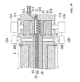
- The present invention will now be described, by way of example only, with reference to the accompanying drawings in which:
-
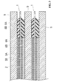
FIG. 1 is a top view of a membrane electrode assembly in accordance with a first embodiment; -
FIG. 2 is a partial cross-sectional view taken along the line II-II ofFIG. 1 ; -
FIG. 3 is a partial cross-sectional view of a fuel cell; -
FIG. 4 is a top view of a pre-assembly before a gasket portion is molded; -
FIG. 5 is a partial cross-sectional view taken along the line V-V ofFIG. 4 ; -
FIG. 6 is a side view of a manufacturing apparatus of a membrane electrode assembly in accordance with the first embodiment; -
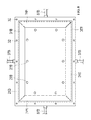
FIG. 7 is a top view of a first mold cast taken along the line VII-VII ofFIG. 6 ; -
FIG. 8 is a top view of a second mold cast taken along the line VIII-VIII ofFIG. 6 ; -
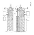
FIG. 9 is a partial cross-sectional view taken along the line IX-IX ofFIG. 6 ; -
FIG. 10 is a partial cross-sectional view when the pre-assembly is loaded on the manufacturing apparatus in accordance with the first embodiment; -
FIG. 11 is a partial cross-sectional view when a mold cast of the manufacturing apparatus is mold-clamped; -
FIG. 12 is a partial cross-sectional view when a resin material is injected into the mold cast of the manufacturing apparatus; -
FIG. 13 is a partial cross-sectional view of a manufacturing apparatus of a membrane electrode assembly in accordance with a second embodiment; -
FIG. 14 is a partial cross-sectional view when a part of filling materials and the pre-assembly are loaded on the manufacturing apparatus in accordance with the second embodiment; -
FIG. 15 is a partial cross-sectional view just before mold-clamping the mold cast of the manufacturing apparatus; -
FIG. 16 is a partial cross-sectional view when the mold cast of the manufacturing apparatus is mold-clamped, thereby being compression-molded; -
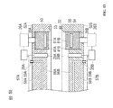
FIG. 17 is a partial cross-sectional view of a manufacturing apparatus of a membrane electrode assembly in accordance with a third embodiment; -
FIG. 18 is a partial cross-sectional view when a part of filling materials and the pre-assembly are loaded on the manufacturing apparatus in accordance with the third embodiment; -
FIG. 19 is a partial cross-sectional view when the mold cast of the manufacturing apparatus is mold-clamped; and -
FIG. 20 is a partial cross-sectional view when the compression-molding and the injection molding are completed after the mold cast of the manufacturing apparatus is mold-clamped. - As shown in
FIGS. 1 and2 , amembrane electrode assembly 1 in accordance with a first embodiment has a stacking structure wherein a solidpolymer electrolyte membrane 2 is inserted between ananode 3 and acathode 4. The solidpolymer electrolyte membrane 2 may include a perfluorocarbon polymer membrane having a sulfonic acid base. An example of this is Nafion 1128®. Theanode 3 comprises a firstcatalytic layer 5A and a firstgas diffusion layer 6A, while thecathode 4 comprises a secondcatalytic layer 5B and a secondgas diffusion layer 6B. At the edges of themembrane electrode assembly 1, afirst gasket portion 8A and asecond gasket portion 8B formed with resin materials are integrally installed on each side of theelectrolyte membrane 2 and around the edges of thecatalytic layers gas diffusion layers gasket portions gasket portions electrolyte membrane 2 do not extend as high as the surfaces of the first and secondgas diffusion layers gas diffusion layers second gasket portions gasket portions inclined surfaces - The resin materials used for the
gasket portions - As shown in
FIG. 3 , themembrane electrode assembly 1 overlaps with aseparator 9 when constituting a fuel cell. At this time, thegasket portions 8A and 8b are adhered to theseparator 9, thereby functioning to prevent leakage of fuel gas or coolant. Since thegas diffusion layers gasket portions gasket portions gas diffusion layers gas diffusion layers gasket portions gasket portions - The manufacturing apparatus of the membrane electrode assembly in accordance with the first embodiment comprises an apparatus for installing a pre-assembly 21 as illustrated in
FIGS. 4 and5 , which forms thecatalytic layers gas diffusion layers electrolyte membrane 2. The apparatus also integrally injection-molds or injection thermal compression-molds thegasket portions electrolyte membrane 2. The pre-assembly 21 has a plurality of through-holes 22 along the edge portion of theelectrolyte membrane 2. - As shown in
FIGS. 6 to 9 , themanufacturing apparatus 20 of the membrane electrode assembly comprises a pair of first and second mold casts 25A and 25B, respectively including a firstmoveable block 24A and a secondmoveable block 24B therein. Themanufacturing apparatus 20 further comprises a pressing device (not shown) for pressing the first and second mold casts 25A and 25B, afirst driving portion 26A and asecond driving portion 26B for driving the first and secondmoveable blocks first control portion 28A and asecond control portion 28B (shown inFIG. 9 ) for controlling the first andsecond driving portions first measuring portion 29A for measuring a total thickness of the firstcatalytic layer 5A and the firstgas diffusion layer 6A, and asecond measuring portion 29B for measuring a total thickness of the secondcatalytic layer 5B and the secondgas diffusion layer 6B. The first andsecond measuring portions - Referring to
FIG. 9 , the first mold cast 25A and the second mold cast 25B can be relatively closely spaced by the pressing device. A first grippingportion 31 A and a second grippingportion 31 B for inserting and gripping the edge portion of theelectrolyte membrane 2 are formed on outer peripheries of each opposite surface of the first and second mold casts 25A, 25B. A plurality ofprojections 32 are formed on a surface of the second grippingportion 31 B opposite to the firstgripping portion 31A in a circumferential direction, while afitting portion 33 is formed on a surface of the firstgripping portion 31A opposite to the second grippingportion 31 B. Theprojections 32 are matingly received by thefitting portions 33. Since inner side corner portions of the first and secondgripping portions electrolyte membrane 2, gripping portion inclinedsurfaces more gates surfaces - The
gates gates supply pipes supply pipes - In each opposite surface of the first mold cast 25A and the second mold cast 25B, a first
block receiving portion 39A and a secondblock receiving portion 39B, each in a shape of a recessed groove, are formed along the inner side surfaces of thegripping portions moveable block 24A is received in the firstblock receiving portion 39A, while the secondmoveable block 24B is received in the secondblock receiving portion 39B. As shown inFIGS. 7 and8 , corresponding to the shapes of the firstblock receiving portion 39A and the secondblock receiving portion 39B, the firstmoveable block 24A and the secondmoveable block 24B are installed by being divided into four blocks in a circumferential direction. However, the four blocks are provided as a non-limiting example, and the number of divisions is not limited. Further, the blocks need not be divided. - The first
moveable block 24A is configured to be forwardly and backwardly moveable toward a direction of the installed pre-assembly 21 by thefirst driving portion 26A having a servo motor, cylinder, or the like. Further, the secondmoveable block 24B is also configured to be forwardly and backwardly moveable toward a direction of the installed pre-assembly 21 by thesecond driving portion 26B having a servo motor, cylinder, or the like. In the firstmoveable portion 24A and the secondmoveable portion 24B, a first opposite surface and a second opposite surface opposed to the pre-assembly 21 are formed. Opposite surfaceinner side portions gripping portions gas diffusion layers moveable blocks second control portions - The
first control portion 28A and thesecond control portion 28B are generally implemented by software stored on, for example, memory of a computer and operated by a central processing unit (CPU). - In the
first mold cast 25A, one or morefirst measuring portions 29A for measuring the thickness of the firstcatalytic layer 5A and the firstgas diffusion layer 6A are installed at a position opposite to the firstgas diffusion layer 6A of the pre-assembly 21. Thefirst measuring portion 29A is, for example, a pressure gauge wherein the thicknesses of the firstcatalytic layer 5A and the firstgas diffusion layer 6A are converted from a pressure when contacting the firstgas diffusion layer 6A with a predetermined protruding amount. Further, thefirst measuring portion 29A, for example, may include a displacement gauge. Each first measuringportion 29A is connected to thefirst control portion 28A, and a measuring signal from thefirst measuring portion 29A is input to thefirst control portion 28A. Thefirst control portion 28A calculates an average of the thicknesses of the firstcatalytic layer 5A and the firstgas diffusion layer 6A based on signals from a plurality of thefirst measuring portions 29A. According to the result of such a measurement, the firstmoveable block 24A can be forwardly and backwardly moved. - Similarly, in the second mold cast 25B, one or more second measuring
portions 29B for measuring the thickness of the secondcatalytic layer 5B and the secondgas diffusion layer 6B are installed at a position opposite to the secondgas diffusion layer 6B of the pre-assembly 21. Thesecond measuring portion 29B is, for example, a pressure gauge wherein the thicknesses of the secondcatalytic layer 5B and the secondgas diffusion layer 6B are converted from a pressure when contacting the secondgas diffusion layer 6B with a predetermined protruding amount. Further, thesecond measuring portion 29B, for example, may include a displacement gauge. Eachsecond measuring portion 29B is connected to thesecond control portion 28B, and a measuring signal from thesecond measuring portion 29B is input to thesecond control portion 28B. Thesecond control portion 28B calculates an average of the thicknesses of the secondcatalytic layer 5B and the secondgas diffusion layer 6B based on signals from a plurality of thesecond measuring portions 29B. According to a result of such a measurement, the secondmoveable block 24B can be forwardly and backwardly moved. - Next, a manufacturing method of the
membrane electrode assembly 1 in accordance with the first embodiment is explained. - First, as shown in
FIG. 10 , the pre-assembly 21 is installed in the second mold cast 25B. At this time, theprojection 32 of the second mold cast 25B is inserted through the throughhole 22 of the pre-assembly 21. As a result, the pre-assembly 21 can be securely retained and supported at the time of the injection molding operation. - Thereafter, as shown in
FIG. 11 , the first mold cast 25A and the second mold cast 25B are closed by the pressing device, thereby being mold-clamped. By doing so, theelectrolyte membrane 2 of the pre-assembly 21 is inserted and gripped between the first grippingportion 31 A and the second grippingportion 31 B. Theprojection 32 of the second grippingportion 31 B is fitted into thefitting portion 33 of the firstgripping portion 31A. Further, as the firstmoveable block 24A and the secondmoveable block 24B approach each other, the opposite surfaceinner side portions gas diffusion layers first injection space 42A and asecond injection space 42B are formed on an outer side of thegas diffusion layers catalytic layers electrolyte membrane 2. - Next, based on the pressure value from the plurality of the
first measuring portions 29A sent to thefirst control portion 28A, an average of the thicknesses of the firstcatalytic layer 5A and the firstgas diffusion layer 6A is calculated. Then, the firstmoveable block 24A is forwardly and backwardly moved by controlling thefirst driving portion 26A by a predetermined amount according to such a calculated result. Here, it is desirable that the pressure value measured by thefirst measuring portion 29A and the average of the thicknesses of the firstcatalytic layer 5A and the firstgas diffusion layer 6A are stored and calculated by previously measuring a relationship between the pressure value and the thickness by an experiment. Further, instead of measuring the pressure value, the measurement can be performed by using a displacement gauge or laser measuring instrument. However, at this time, it is not necessary to convert the thickness from the pressure by a previous experiment. As described above, since known techniques can be appropriately applied to measure the thickness, the details thereof are omitted herein. - Similar to the above, based on the signal input from the plurality of the
second measuring portions 29B to thesecond control portion 28B, an average of the thicknesses of the secondcatalytic layer 5B and the secondgas diffusion layer 6B is calculated. Then, the secondmoveable block 24B is forwardly and backwardly moved by controlling thesecond driving portion 26B by a predetermined amount according to such a calculated result. - The thicknesses of the
catalytic layers gas diffusion layers gas diffusion layers polymer electrolyte membrane 2 and simply adding the approximate thicknesses of the catalytic layers (about 3 to 20 µm or 0 since the value is extremely small). However, operating performance may be deteriorated as this is not as accurate as the present embodiment. - Thereafter, as shown in
FIG. 12 , the resin materials are injected from thesupply pipes gates first injection space 42A and thesecond injection space 42B. - When the resin material is a thermoplastic resin, the
membrane electrode assembly 1 is extracted wherein thefirst gasket portion 8A and thesecond gasket portion 8B are molded by releasing the first mold cast 25A and the second mold cast 25B after the resin material is injected in a fused state and the resin material is hardened due to a drop in temperature. - When the resin material is a thermosetting resin, the
membrane electrode assembly 1 is extracted wherein thefirst gasket portion 8A and thesecond gasket portion 8B are molded by releasing the first mold cast 25A and the second mold cast 25B after the resin material in a liquid phase is injected. The resin material is then hardened by heating at a temperature higher than a hardening temperature by a heater (not shown) installed in the first mold cast 25A and the second mold cast 25B. - According to the
membrane electrode assembly 1 manufactured as above, since the resin material is injected from theinclined surfaces gates separator 9. Further, adhesion with theseparator 9 can be favorably maintained when constituting the fuel cell. - According to the thicknesses of the
catalytic layer 5A and thegas diffusion layer 6A, as well as thecatalytic layer 5B and thegas diffusion layer 6B, since eachmoveable block catalytic layers gasket portions gas diffusion layers - Such an optimum thickness is, for example, established such that the thicknesses H1 and H2 of the gaskets are respectively determined as 80% of the thicknesses of the
catalytic layer 5A and thegas diffusion layer 6A and the thicknesses of thecatalytic layer 5B and thegas diffusion layer 6B. Further, such a ratio can be appropriately varied according to the types of the gas diffusion layers. - Also, at the time of the injection-molding operation, since the
moveable blocks gas diffusion layers gas diffusion layers gas diffusion layers - Further, the thicknesses H1 and H2 of the
gasket portions catalytic layer 5A and thegas diffusion layer 6A, as well as thecatalytic layer 5B and thegas diffusion layer 6B, by the measuringportions gas diffusion layers gas diffusion layers - Because the step heights H3 and H4 can be established separately, even when the materials of an anode side and a cathode side of the
gas diffusion layers - The
gasket portions - According to the
membrane electrode assembly 1 of this embodiment, since thegasket portions - A
manufacturing apparatus 50 of a membrane electrode assembly and a manufacturing method in accordance with a second embodiment differ from themanufacturing apparatus 20 and the manufacturing method in accordance with the first embodiment. Specifically, thegasket portions gasket portions membrane electrode assembly 1 manufactured in the second embodiment has the same structure of themembrane electrode assembly 1 in the first embodiment. - As to the portions having the same functions as in the first embodiment, same reference numerals are denoted and explanations thereof are omitted in order to avoid repetition.
- The
manufacturing apparatus 50 of the membrane electrode assembly in accordance with the second embodiment comprises an apparatus for installing the pre-assembly 21 as inFIGS. 4 and5 , which forms thecatalytic layers gas diffusion layers electrolyte membrane 2. The apparatus also integrally compression-molds thegasket portions electrolyte membrane 2. - As shown in
FIG. 13 , themanufacturing apparatus 50 comprises a pair of afirst mold cast 52A and asecond mold cast 52B, respectively including a firstmoveable block 51A and a secondmoveable block 51 B therein. - The first
moveable block 51A comprises afirst heating portion 53, which is used to heat the firstmoveable block 51 A. Thefirst heating portion 53 has is elongated along a length direction of the firstmoveable block 51A. A heat transfer heater unit is advantageously used for thefirst heating portion 53 in the present embodiment, although other structures (e.g., a structure of using a high frequency heater or leaking a high temperature fluid) may be applied. Further, since the heat transfer heater unit is a known device, the detailed explanations thereof is omitted herein. Thefirst heating portion 53 is connected to an external power source unit (not shown), and a temperature of thefirst heating portion 53 can be arbitrarily established by controlling the power source unit. - The second
moveable block 51 B comprises asecond heating portion 54 for heating the secondmoveable block 51 B and ablock cooling portion 55 for cooling the secondmoveable block 51 B. Thesecond heating portion 54 is elongated along a length direction of the second moveable block 51 B. A high frequency heater unit capable of rapid heating is beneficial as thesecond heating portion 54 in the present embodiment, although other structures (e.g., a structure of using a heat transfer heater or leaking a high temperature fluid) may be applied. Further, since the high frequency heater unit is a known device, the detailed explanations thereof are omitted herein. Thesecond heating portion 54 is connected to an external power source unit (not shown), and a temperature of thesecond heating portion 54 can be arbitrarily established by controlling the power source unit. - The
block cooling portion 55 is elongated along a length direction of the second moveable block 51 B. A Peltier system cooling element is advantgeous for theblock cooling portion 55 in the present embodiment, although other structures (e.g., a structure of leaking a low temperature fluid) may be applied. Theblock cooling portion 55 is connected to an external power source unit (not shown), and a temperature of theblock cooling portion 55 can be arbitrarily established by controlling the power source unit. - In a
first center portion 56A of thefirst mold cast 52A surrounded by the firstmoveable block 51A, a first moldcast cooling portion 57A is installed. Further, in asecond center portion 56B of thesecond mold cast 52B surrounded by the secondmoveable block 52B, a second moldcast cooling portion 57B is installed. - The first mold
cast cooling portion 57A and the second moldcast cooling portion 57B comprise a firstcooling flow path 58A and a secondcooling flow path 58B, respectively. A cooling medium (e.g., coolant water) can be supplied from an external cooling fluid supply source (not shown) via coolingfluid supply pipes cooling flow path 58A and the secondcooling flow path 58B. The firstcooling flow path 58A is formed as a plurality of flow paths along a length direction of each firstmoveable block 51 A so as to surround four sides of thefirst center portion 56A. The secondcooling flow path 58B is also formed as a plurality of flow paths along a length direction of each secondmoveable block 51 B so as to surround four sides of thesecond center portion 56B. Shapes of the flow paths are not specifically limited but may include a formation of a single path rather than a plurality of paths bent in a rectangular shape along length directions of the first and secondmoveable block - Next, a manufacturing method of the membrane electrode assembly in accordance with the second embodiment is explained.
- First, the
first center portion 56A and thesecond center portion 56B of the first mold cast 52A and the second mold cast 52B are cooled by supplying the cooling medium from the cooling fluid supply source to the first and secondcooling flow paths moveable block 51A is heated by operating thefirst heating portion 53. Heating of the firstmoveable block 51A while cooling thefirst center portion 56A and thesecond center portion 56B is maintained all the time during a processing cycle. - Then, the second
moveable block 51 B is cooled by operating theblock cooling portion 55. - Next, as shown in
FIG. 14 , a secondresin filling material 60B is loaded on the secondmoveable block 51 B of the second mold cast 52B. Then, the pre-assembly 21 is installed on the second mold cast 52B. At this time, since theprojection 32 of thesecond mold cast 52B is inserted through the through-hole 22 of the pre-assembly 21, the pre-assembly 21 can be securely retained and supported at the time of a compression-molding operation, which is explained below. Thereafter, as shown inFIG. 15 , a firstresin filling material 60A is loaded on a position corresponding to the firstmoveable block 51 A of the pre-assembly 21. - The first and
second filling materials second filling materials second filling materials second filling materials gas diffusion layers second filling materials - Thereafter, as shown in
FIG. 16 , the first mold cast 52A and thesecond mold cast 52B are closed by the pressing means to thereby become mold-clamped, while being rapidly heated by stopping operation of theblock cooling portion 55 of the secondmoveable block 51 B and operating thesecond heating portion 54. At this time, theelectrolyte membrane 2 of the pre-assembly 21 is inserted and gripped between the firstgripping portion 31A and the second gripping portion 31 B. Further, theprojection 32 of the second grippingportion 31 B is fitted in thefitting portion 33 of the firstgripping portion 31A. Also, the firstmoveable block 51A and the secondmoveable block 51 B are pressed toward each other so that the opposite surfaceinner side portions gas diffusion layers - The first and
second filling materials moveable block 51 A and the secondmoveable block 51 B heated by thefirst heating portion 53 and thesecond heating portion 54. While the first andsecond filling materials catalytic layer 5A and the firstgas diffusion layer 6A is calculated by a plurality of thefirst measuring portions 29A. Based on a predetermined amount according to the calculated average value of the thicknesses of the firstcatalytic layer 5A and the firstgas diffusion layer 6A, the firstmoveable block 51A is forwardly and backwardly moved by controlling thefirst driving portion 26A. - Likewise, while the first and
second filling materials catalytic layer 5B and the secondgas diffusion layer 6B is calculated by a plurality of thesecond measuring portions 29B. Based on a predetermined amount according to such a calculated result, the secondmoveable block 51 B is forwardly and backwardly moved by controlling thesecond driving portion 26B. - Thereafter, until the first and
second filling materials moveable blocks second mold cast 52B are released. By doing so, themembrane electrode assembly 1 wherein thefirst gasket portion 8A and thesecond gasket portion 8B are molded is extracted. - Next, the heating is ended by stopping the operation of the
second heating portion 54. The secondmoveable block 51 B is cooled by operating theblock cooling portion 55. After a temperature of the secondmoveable block 51 B is decreased to a predetermined temperature, the manufacturing of themembrane electrode assembly 1 below is started. - As in the
above manufacturing apparatus 50 and the manufacturing method in accordance with the second embodiment, despite using the compression-molding operation and not the injection-molding or injection thermal compression-molding operation, thegasket portions catalytic layer 5A and thegas diffusion layer 6A, as well as thecatalytic layer 5B and thegas diffusion layer 6B as in the first embodiment. - Further, as an effect differing from the first embodiment, since the first and second mold cast
cooling portions second center portion gas diffusion layers - Moreover, since the
second filling material 60B is arranged under the pre-assembly 21 before the first mold cast 52A and thesecond mold cast 52B are mold-clamped, a downward suspension of the pre-assembly 21 is prevented by thesecond filling material 60B. The pre-assembly 21 can be retained and supported at a more appropriate position. - Also, since the first and
second heating portions moveable blocks - Further, since the
block cooling portion 55 is installed in the secondmoveable block 51 B, the secondmoveable block 51 B wherein thesecond filling material 60B is arranged can be intensively cooled. Thus, when themembrane electrode assembly 1 is sequentially manufactured, since the secondmoveable block 51 B can be cooled in a short time, the working hours can be reduced. - Also, the first and second mold cast
cooling portions second heating portions block cooling portion 55 of themanufacturing apparatus 50, which are in accordance with the second embodiment, are applicable to the first embodiment. - A
manufacturing apparatus 70 of a membrane electrode assembly and a manufacturing method in accordance with a third embodiment differ from themanufacturing apparatuses gasket portion 8A at one side is injection-molded or injection thermal compression-molded while thegasket portion 8A at the other side is compression-molded. Further, themembrane electrode assembly 1 in the third embodiment has the same structure as themembrane electrode assembly 1 in the first and second embodiments. As to the portions having the same functions as in the first embodiment, same reference numerals are denoted, and the explanations thereof are omitted herein in order to avoid repetition. - The
manufacturing apparatus 70 of the membrane electrode assembly in accordance with the third embodiment comprises an apparatus for installing the pre-assembly 21 as seen inFIGS. 4 and5 , which forms thecatalytic layers gas diffusion layers electrolyte membrane 2, and for injection molding or injection thermal compression-molding thegasket portion 8A at one side and compression-molding thegasket portion 8B at the other side of theelectrolyte membrane 2. - Such a
manufacturing apparatus 70 of the membrane electrode assembly is the same as themanufacturing apparatus 50 in accordance with the second embodiment, except that agate 72 is formed on afirst mold cast 71A, and asupply pipe 73 for supplying a resin material is connected to thegate 72. Similar to thegate 36A in the first embodiment, thegate 72 is formed of a pin gate or a film gate having a width in the shape of a film. - Next, a manufacturing method of the membrane electrode assembly in accordance with the third embodiment is explained below.
- First, the
first center portion 56A and thesecond center portion 56B of the first mold cast 71A and the second mold cast 71 B are cooled by supplying the cooling medium from the cooling fluid supply source to the first and secondcooling flow paths moveable block 51A is heated by operating thefirst heating portion 53. Heating the firstmoveable block 51A while cooling thefirst center portion 56A and thesecond center portion 56B are maintained all the time during a processing cycle. Then, the secondmoveable block 51 B is cooled by operating theblock cooling portion 55. - Next, as shown in
FIG. 18 , a secondresin filling material 74 is loaded on the secondmoveable block 51 B of the second mold cast 71 B. Then, the pre-assembly 21 is installed on the second mold cast 71 B. At this time, since theprojection 32 of the second mold cast 71 B is inserted through the through-hole 22 of the pre-assembly 21, the pre-assembly 21 can be securely retained and supported at the time of a compression-molding operation, as explained below. - The
second filling material 74 described above is a material in the shape of a sheet mainly consisting of thermosetting resins as in the second embodiment. For example, such a material can be injected in any position by suctioning with a suction pad in the shape of a sponge. Further, thesecond filling material 74 may include a powder material, a semi-hardened material obtained by pre-heating the powder material or a gel material (i.e., slurry material). In the case of the powder or gel, thesecond filling material 74 can be input at an arbitrary position by being discharged from a nozzle. Also, thesecond filling material 74 is formed in an annular shape surrounding an outer periphery of thegas diffusion layer 6B, although thesecond filling material 74 may be installed by being divided into a plurality of pieces. - Thereafter, as shown in
FIG. 19 , the first mold cast 71A and the second mold cast 71 B are closed by the pressing device to thereby become mold-clamped, while being rapidly heated by stopping operation of theblock cooling portion 55 of the secondmoveable block 51 B and operating thesecond heating portion 54. At this time, theelectrolyte membrane 2 of the pre-assembly 21 is inserted and gripped between the firstgripping portion 31A and the second gripping portion 31 B. Further, theprojection 32 of the second grippingportion 31 B is fitted in thefitting portion 33 of the firstgripping portion 31A. The firstmoveable block 51 A and the secondmoveable block 51 B are in contact so that the opposite surfaceinner side portions gas diffusion layers first injection space 75 is formed at outer sides of thegas diffusion layer 6A and thecatalytic layer 5A of theelectrolyte membrane 2. - The
second filling material 74 is fused by the secondmoveable block 51 B heated by thesecond heating portion 54. While thesecond filling material 74 is in a fused state, an average value of the thicknesses of the firstcatalytic layer 5A and the firstgas diffusion layer 6A is calculated by a plurality of thefirst measuring portions 29A. Based on a predetermined amount according to the calculated result, the firstmoveable block 51A is forwardly and backwardly moved by controlling thefirst driving portion 26A. - Likewise, while the first and
second filling materials catalytic layer 5B and the secondgas diffusion layer 6B is calculated by a plurality of thesecond measuring portions 29B. Based on a predetermined amount according to such a calculated result, the secondmoveable block 51 B is forwardly and backwardly moved by controlling thesecond driving portion 26B. - Thereafter, as shown in
FIG. 20 , the resin material is injected from thesupply pipe 73 through thegate 72 to thefirst injection space 75. Also, it is desirable if the same material as thesecond filling material 74 is used for the resin material, although the invention is not limited to such a configuration. - Until the
second filling material 74 and the injected resin material are hardened, the positions and temperatures of the first and second moveable blocks 51 A and 51 B are maintained. Also, when a hardening reaction is ended, meaning the shapes of thesecond filling material 74 and the resin material can be maintained despite being released, the first mold cast 71 A and the second mold cast 71 B are released. By doing so, themembrane electrode assembly 1 with the moldedfirst gasket portion 8A and thesecond gasket portion 8B is extracted. Thereafter, the heating is ended by stopping the operation of thesecond heating portion 54. - Then, the second
moveable block 51 B is cooled by operating theblock cooling portion 55. After a temperature of the secondmoveable block 51 B is decreased to a predetermined temperature, the manufacturing of themembrane electrode assembly 1 is started. - As in the
above manufacturing apparatus 70 and the manufacturing method in accordance with the third embodiment, even when using a mixture of the compression-molding operation with the injection molding operation or the injection thermal compression-molding operation, thegasket portions catalytic layer 5A and thegas diffusion layer 6A, as well as thecatalytic layer 5B and thegas diffusion layer 6B, as in the first and second embodiments. - While certain embodiments of the invention are described above, the invention may include other embodiments and modifications without deviating from the subject matter or scope of the present invention and may be varied in the range of the claims. For example, the
projection 32 may be formed on thefirst mold cast 25A. Further, as long as the pre-assembly 21 can be retained and supported at the time of the injection-molding operation, the projection is not necessarily formed. - The above-described embodiments have been described in order to allow easy understanding of the invention and do not limit the invention. On the contrary, the invention is intended to cover various modifications and equivalent arrangements included within the scope of the appended claims, which scope is to be accorded the broadest interpretation so as to encompass all such modifications and equivalent structure as is permitted under the law.
- This application claims priority from Japanese Patent Application Nos.
2007-070874, filed 19th March 2007 2007-304692, filed 26th November 2007
Claims (12)
- A method of manufacturing a membrane electrode assembly having both a catalytic layer and a gas diffusion layer on opposing surfaces of an electrolyte membrane, the method comprising:measuring thicknesses of the catalytic layer and the gas diffusion layer;determining a thickness of a gasket portion according to the thicknesses of the catalytic layer and the gas diffusion layer; andmolding the gasket portion having the determined thickness around at least a portion of the catalytic layer and the gas diffusion layer.
- A method as claimed in claim 1, comprising compressing the catalytic layer and the gas diffusion layer until a thickness of the catalytic layer and the gas diffusion layer is approximately equal to the thickness of the gasket portion.
- A method as claimed in claim 1 or claim 2, wherein the catalytic layer and the gas diffusion layer are compressed with a separator.
- A method as claimed in any preceding claim, wherein the gasket portion comprises a resin material.
- A method as claimed in any preceding claim, wherein the gasket portion is molded by injection-molding, compression molding or injection compression-molding.
- A method as claimed in claim 5, wherein molding the gasket portion comprises:forming a molding space with a mold cast; andinjecting resin material into the molding space through a gate in the mold cast, wherein an inclined surface is formed at an outer peripheral edge portion of the gasket portion at a region of the gate.
- A method as claimed in claim 6, wherein the gate is a pin gate or a film gate.
- An apparatus for manufacturing a membrane electrode assembly having both a catalytic layer and a gas diffusion layer on opposing surfaces of an electrolyte membrane, the apparatus comprising:a mold cast comprising a gripping portion configured to grip an edge portion of the catalytic and the gas diffusion layers;a measuring portion configured to measure thicknesses of the catalytic layer and the gas diffusion layer;a moveable block operable to move forward and backward against the electrolyte membrane along an inner side surface of the gripping portion, the moveable block having a side opposite the gripping portion and adjacent to an outer peripheral end of the gas diffusion layer; anda control portion configured to control the forward-backward movement of the moveable block according to the thicknesses of the catalytic layer and the gas diffusion layer.
- An apparatus as claimed in claim 8, wherein the gripping portion has an inclined surface, the apparatus further comprising a gate through which a resin material is injected, the gate being positioned at the inclined surface of the gripping portion.
- An apparatus as claimed in claim 8 or claim 9, wherein the moveable block has at least one of:a heating portion configured to heat the moveable block; anda block cooling portion configured to cool the moveable block.
- An apparatus as claimed in any of claims 8 to 10, wherein the mold cast has a mold cast cooling portion configured to cool a region of the mold cast adjacent to the gas diffusion layer.
- A membrane electrode assembly formed using the method or apparatus as claimed in any preceding claim, or a vehicle having such a membrane electrode assembly.
Applications Claiming Priority (2)
| Application Number | Priority Date | Filing Date | Title |
|---|---|---|---|
| JP2007070874 | 2007-03-19 | ||
| JP2007304692A JP5298511B2 (en) | 2007-03-19 | 2007-11-26 | Membrane electrode assembly manufacturing method, membrane electrode assembly, and apparatus for manufacturing the same |
Publications (3)
| Publication Number | Publication Date |
|---|---|
| EP1973184A2 true EP1973184A2 (en) | 2008-09-24 |
| EP1973184A3 EP1973184A3 (en) | 2008-12-03 |
| EP1973184B1 EP1973184B1 (en) | 2016-01-13 |
Family
ID=39591863
Family Applications (1)
| Application Number | Title | Priority Date | Filing Date |
|---|---|---|---|
| EP08152826.7A Ceased EP1973184B1 (en) | 2007-03-19 | 2008-03-17 | Membrane electrode assembly and method of manufacturing same |
Country Status (3)
| Country | Link |
|---|---|
| US (1) | US7927086B2 (en) |
| EP (1) | EP1973184B1 (en) |
| CA (1) | CA2625903C (en) |
Cited By (2)
| Publication number | Priority date | Publication date | Assignee | Title |
|---|---|---|---|---|
| WO2009116103A1 (en) * | 2008-03-21 | 2009-09-24 | Exergy Fuel Cells S.R.L. | Electro-chemical device with optimized electrode insulation |
| EP2525429A4 (en) * | 2010-01-14 | 2014-01-01 | Honda Motor Co Ltd | Fuel cell |
Families Citing this family (5)
| Publication number | Priority date | Publication date | Assignee | Title |
|---|---|---|---|---|
| JP2009269380A (en) * | 2008-05-12 | 2009-11-19 | Central Glass Co Ltd | Mold for injection molding of framed glass |
| FI127413B (en) * | 2008-11-19 | 2018-05-31 | Outotec Oyj | Method and apparatus for providing the edge of a base plate for an electrode to be used in electrolytic refining or metal extraction with a plastic strip |
| US10044047B2 (en) * | 2010-01-05 | 2018-08-07 | Panasonic Intellectual Property Management Co., Ltd. | Electrode-membrane-frame assembly, method for producing the same, and fuel cell |
| WO2016157714A1 (en) | 2015-03-30 | 2016-10-06 | パナソニックIpマネジメント株式会社 | Fuel cell and method for manufacturing fuel cell |
| KR101908254B1 (en) * | 2015-03-31 | 2018-10-15 | 혼다 기켄 고교 가부시키가이샤 | Separator for fuel cells and method for producing same |
Citations (4)
| Publication number | Priority date | Publication date | Assignee | Title |
|---|---|---|---|---|
| WO2001017048A1 (en) | 1999-09-01 | 2001-03-08 | Nok Corporation | Fuel cell |
| US20020034670A1 (en) | 2000-07-19 | 2002-03-21 | Toshihiko Suenaga | Seal for fuel cell and forming method therefor |
| US20050255372A1 (en) | 2002-01-22 | 2005-11-17 | Lertola James G | Unitized membrane electrode assembly and process for its preparation |
| EP1624515A1 (en) | 2004-05-28 | 2006-02-08 | Du Pont Canada Inc. | Unitized electrochemical cell sub-assembly and the method of making the same |
Family Cites Families (4)
| Publication number | Priority date | Publication date | Assignee | Title |
|---|---|---|---|---|
| FR2546812B1 (en) * | 1983-05-30 | 1986-04-18 | Saint Gobain Vitrage | |
| FR2572987B1 (en) * | 1984-09-21 | 1987-01-02 | Pont A Mousson | METHOD AND DEVICE FOR OVER-MOLDING A SURROUNDING OF PRECISE DIMENSIONS ON THE SURROUNDING OF A FLAT OR GALBED PART WITH DIMENSIONAL TOLERANCES |
| EP0354481B1 (en) * | 1988-08-09 | 1995-11-29 | Asahi Glass Company Ltd. | Method of preparing window glass with a gasket and a shaping mold for preparing such window glass |
| KR970002295B1 (en) * | 1993-02-23 | 1997-02-27 | 미쯔비시 덴끼 가부시끼가이샤 | Injection molding method |
-
2008
- 2008-03-13 US US12/047,729 patent/US7927086B2/en active Active
- 2008-03-17 CA CA2625903A patent/CA2625903C/en active Active
- 2008-03-17 EP EP08152826.7A patent/EP1973184B1/en not_active Ceased
Patent Citations (4)
| Publication number | Priority date | Publication date | Assignee | Title |
|---|---|---|---|---|
| WO2001017048A1 (en) | 1999-09-01 | 2001-03-08 | Nok Corporation | Fuel cell |
| US20020034670A1 (en) | 2000-07-19 | 2002-03-21 | Toshihiko Suenaga | Seal for fuel cell and forming method therefor |
| US20050255372A1 (en) | 2002-01-22 | 2005-11-17 | Lertola James G | Unitized membrane electrode assembly and process for its preparation |
| EP1624515A1 (en) | 2004-05-28 | 2006-02-08 | Du Pont Canada Inc. | Unitized electrochemical cell sub-assembly and the method of making the same |
Cited By (3)
| Publication number | Priority date | Publication date | Assignee | Title |
|---|---|---|---|---|
| WO2009116103A1 (en) * | 2008-03-21 | 2009-09-24 | Exergy Fuel Cells S.R.L. | Electro-chemical device with optimized electrode insulation |
| EP2525429A4 (en) * | 2010-01-14 | 2014-01-01 | Honda Motor Co Ltd | Fuel cell |
| US9559376B2 (en) | 2010-01-14 | 2017-01-31 | Honda Motor Co., Ltd. | Fuel cell with an electrolyte membrane and gas diffusion layers |
Also Published As
| Publication number | Publication date |
|---|---|
| EP1973184A3 (en) | 2008-12-03 |
| CA2625903C (en) | 2011-02-22 |
| EP1973184B1 (en) | 2016-01-13 |
| US20080230936A1 (en) | 2008-09-25 |
| CA2625903A1 (en) | 2008-09-19 |
| US7927086B2 (en) | 2011-04-19 |
Similar Documents
| Publication | Publication Date | Title |
|---|---|---|
| CA2625903C (en) | Membrane electrode assembly and method of manufacturing same | |
| KR101409667B1 (en) | Module for a fuel cell arrangement | |
| KR101669154B1 (en) | Seal component manufacturing method and mold | |
| EP1223629B1 (en) | Gasket for fuel cell and method of forming it | |
| PT1367664E (en) | Bipolar plate comprising polypropylene as polymer binder | |
| KR100989972B1 (en) | Method for manufacturing membrane electrode assembly, membrane electrode assembly and apparatus for manufacturing same | |
| WO2003092104A1 (en) | Separator for fuel cell | |
| JP2016201357A (en) | Injection metal bead channel seal achieved by plate features pressed on fuel cell bipolar plate | |
| JP5275070B2 (en) | Fuel cell and manufacturing method thereof | |
| JP6383203B2 (en) | Manufacturing method of plate-integrated gasket | |
| US20090261502A1 (en) | Integral molding method of gasket of fuel cell-use component member and molding device thereof | |
| KR102301439B1 (en) | Battery cooling panel structure to reduce the stress concentration in the cooling channel | |
| JP2005268077A (en) | Manufacturing method of fuel cell separator | |
| EP1267434A2 (en) | Fuel cell and its production method | |
| JP2004160772A (en) | Method of forming fuel cell separator | |
| JP2010092733A (en) | Membrane-electrode assembly, and method and apparatus for manufacturing the same | |
| EP2686902B1 (en) | Fuel cell plate bonding method and arrangement | |
| KR20120005183A (en) | Manufacturing method of fuel cell carbon composite separator and fuel cell manufactured therefrom | |
| EP2202833B1 (en) | Gasket for fuel cell and method of forming it | |
| JP2007141792A (en) | Fuel cell and manufacturing method thereof | |
| EP4371744A1 (en) | Molding method and die | |
| US20240364192A1 (en) | Method for manufacturing rotor | |
| JP2006327051A (en) | Injection molding method and injection molding machine | |
| JP5972409B2 (en) | Fuel cell components and fuel cell assemblies | |
| JP2006032075A (en) | Component fuel cell |
Legal Events
| Date | Code | Title | Description |
|---|---|---|---|
| PUAI | Public reference made under article 153(3) epc to a published international application that has entered the european phase |
Free format text: ORIGINAL CODE: 0009012 |
|
| AK | Designated contracting states |
Kind code of ref document: A2 Designated state(s): AT BE BG CH CY CZ DE DK EE ES FI FR GB GR HR HU IE IS IT LI LT LU LV MC MT NL NO PL PT RO SE SI SK TR |
|
| AX | Request for extension of the european patent |
Extension state: AL BA MK RS |
|
| PUAL | Search report despatched |
Free format text: ORIGINAL CODE: 0009013 |
|
| AK | Designated contracting states |
Kind code of ref document: A3 Designated state(s): AT BE BG CH CY CZ DE DK EE ES FI FR GB GR HR HU IE IS IT LI LT LU LV MC MT NL NO PL PT RO SE SI SK TR |
|
| AX | Request for extension of the european patent |
Extension state: AL BA MK RS |
|
| RTI1 | Title (correction) |
Free format text: MEMBRANE ELECTRODE ASSEMBLY AND METHOD OF MANUFACTURING SAME |
|
| 17P | Request for examination filed |
Effective date: 20090527 |
|
| AKX | Designation fees paid |
Designated state(s): DE FR GB |
|
| 17Q | First examination report despatched |
Effective date: 20090925 |
|
| REG | Reference to a national code |
Ref country code: DE Ref legal event code: R079 Ref document number: 602008041982 Country of ref document: DE Free format text: PREVIOUS MAIN CLASS: H01M0004840000 Ipc: H01M0008020000 |
|
| GRAP | Despatch of communication of intention to grant a patent |
Free format text: ORIGINAL CODE: EPIDOSNIGR1 |
|
| RIC1 | Information provided on ipc code assigned before grant |
Ipc: H01M 8/10 20060101ALI20150527BHEP Ipc: H01M 8/02 20060101ALI20150527BHEP Ipc: H01M 8/24 20060101ALI20150527BHEP Ipc: H01M 4/88 20060101ALI20150527BHEP Ipc: H01M 4/84 20060101AFI20150527BHEP |
|
| RIC1 | Information provided on ipc code assigned before grant |
Ipc: H01M 8/02 20060101AFI20150604BHEP Ipc: H01M 8/10 20060101ALN20150604BHEP Ipc: H01M 8/24 20060101ALN20150604BHEP |
|
| INTG | Intention to grant announced |
Effective date: 20150618 |
|
| GRAJ | Information related to disapproval of communication of intention to grant by the applicant or resumption of examination proceedings by the epo deleted |
Free format text: ORIGINAL CODE: EPIDOSDIGR1 |
|
| INTG | Intention to grant announced |
Effective date: 20150623 |
|
| GRAP | Despatch of communication of intention to grant a patent |
Free format text: ORIGINAL CODE: EPIDOSNIGR1 |
|
| INTG | Intention to grant announced |
Effective date: 20150727 |
|
| GRAS | Grant fee paid |
Free format text: ORIGINAL CODE: EPIDOSNIGR3 |
|
| GRAA | (expected) grant |
Free format text: ORIGINAL CODE: 0009210 |
|
| AK | Designated contracting states |
Kind code of ref document: B1 Designated state(s): DE FR GB |
|
| REG | Reference to a national code |
Ref country code: GB Ref legal event code: FG4D |
|
| REG | Reference to a national code |
Ref country code: DE Ref legal event code: R096 Ref document number: 602008041982 Country of ref document: DE |
|
| REG | Reference to a national code |
Ref country code: FR Ref legal event code: PLFP Year of fee payment: 9 |
|
| REG | Reference to a national code |
Ref country code: DE Ref legal event code: R097 Ref document number: 602008041982 Country of ref document: DE |
|
| PLBE | No opposition filed within time limit |
Free format text: ORIGINAL CODE: 0009261 |
|
| STAA | Information on the status of an ep patent application or granted ep patent |
Free format text: STATUS: NO OPPOSITION FILED WITHIN TIME LIMIT |
|
| 26N | No opposition filed |
Effective date: 20161014 |
|
| REG | Reference to a national code |
Ref country code: FR Ref legal event code: PLFP Year of fee payment: 10 |
|
| REG | Reference to a national code |
Ref country code: FR Ref legal event code: PLFP Year of fee payment: 11 |
|
| PGFP | Annual fee paid to national office [announced via postgrant information from national office to epo] |
Ref country code: FR Payment date: 20230222 Year of fee payment: 16 |
|
| PGFP | Annual fee paid to national office [announced via postgrant information from national office to epo] |
Ref country code: GB Payment date: 20230222 Year of fee payment: 16 Ref country code: DE Payment date: 20230221 Year of fee payment: 16 |
|
| REG | Reference to a national code |
Ref country code: DE Ref legal event code: R119 Ref document number: 602008041982 Country of ref document: DE |
|
| GBPC | Gb: european patent ceased through non-payment of renewal fee |
Effective date: 20240317 |
|
| PG25 | Lapsed in a contracting state [announced via postgrant information from national office to epo] |
Ref country code: DE Free format text: LAPSE BECAUSE OF NON-PAYMENT OF DUE FEES Effective date: 20241001 |
|
| PG25 | Lapsed in a contracting state [announced via postgrant information from national office to epo] |
Ref country code: GB Free format text: LAPSE BECAUSE OF NON-PAYMENT OF DUE FEES Effective date: 20240317 |
|
| PG25 | Lapsed in a contracting state [announced via postgrant information from national office to epo] |
Ref country code: FR Free format text: LAPSE BECAUSE OF NON-PAYMENT OF DUE FEES Effective date: 20240331 |
|
| PG25 | Lapsed in a contracting state [announced via postgrant information from national office to epo] |
Ref country code: GB Free format text: LAPSE BECAUSE OF NON-PAYMENT OF DUE FEES Effective date: 20240317 Ref country code: FR Free format text: LAPSE BECAUSE OF NON-PAYMENT OF DUE FEES Effective date: 20240331 Ref country code: DE Free format text: LAPSE BECAUSE OF NON-PAYMENT OF DUE FEES Effective date: 20241001 |