EP1973026A1 - Notebook computer - Google Patents
Notebook computer Download PDFInfo
- Publication number
- EP1973026A1 EP1973026A1 EP06722131A EP06722131A EP1973026A1 EP 1973026 A1 EP1973026 A1 EP 1973026A1 EP 06722131 A EP06722131 A EP 06722131A EP 06722131 A EP06722131 A EP 06722131A EP 1973026 A1 EP1973026 A1 EP 1973026A1
- Authority
- EP
- European Patent Office
- Prior art keywords
- power
- power supply
- notebook computer
- wan module
- network
- Prior art date
- Legal status (The legal status is an assumption and is not a legal conclusion. Google has not performed a legal analysis and makes no representation as to the accuracy of the status listed.)
- Ceased
Links
Images
Classifications
-
- G—PHYSICS
- G06—COMPUTING OR CALCULATING; COUNTING
- G06F—ELECTRIC DIGITAL DATA PROCESSING
- G06F1/00—Details not covered by groups G06F3/00 - G06F13/00 and G06F21/00
- G06F1/26—Power supply means, e.g. regulation thereof
- G06F1/32—Means for saving power
- G06F1/3203—Power management, i.e. event-based initiation of a power-saving mode
- G06F1/3206—Monitoring of events, devices or parameters that trigger a change in power modality
- G06F1/3209—Monitoring remote activity, e.g. over telephone lines or network connections
-
- H—ELECTRICITY
- H04—ELECTRIC COMMUNICATION TECHNIQUE
- H04L—TRANSMISSION OF DIGITAL INFORMATION, e.g. TELEGRAPHIC COMMUNICATION
- H04L12/00—Data switching networks
- H04L12/02—Details
- H04L12/12—Arrangements for remote connection or disconnection of substations or of equipment thereof
-
- Y—GENERAL TAGGING OF NEW TECHNOLOGICAL DEVELOPMENTS; GENERAL TAGGING OF CROSS-SECTIONAL TECHNOLOGIES SPANNING OVER SEVERAL SECTIONS OF THE IPC; TECHNICAL SUBJECTS COVERED BY FORMER USPC CROSS-REFERENCE ART COLLECTIONS [XRACs] AND DIGESTS
- Y02—TECHNOLOGIES OR APPLICATIONS FOR MITIGATION OR ADAPTATION AGAINST CLIMATE CHANGE
- Y02D—CLIMATE CHANGE MITIGATION TECHNOLOGIES IN INFORMATION AND COMMUNICATION TECHNOLOGIES [ICT], I.E. INFORMATION AND COMMUNICATION TECHNOLOGIES AIMING AT THE REDUCTION OF THEIR OWN ENERGY USE
- Y02D30/00—Reducing energy consumption in communication networks
- Y02D30/50—Reducing energy consumption in communication networks in wire-line communication networks, e.g. low power modes or reduced link rate
Definitions
- the present invention relates to the field of computer technology, and in particular to a notebook computer.
- a user After access to the network and surfing the Internet by means of a WAN module, a user usually leaves his or her SIM card in the WAN module while the notebook computer enters a power-off state or a sleep state. In this case, if there is information (e.g., phone call or short message) sent from a wireless network, such as GPRS or CDMA network, the user can not receive such information.
- information e.g., phone call or short message
- the WAN module is not provided with power if the computer is in a power-off state or sleep state, and thus all operations associated with the WAN module are un-activated. Even when the WAN module has been supplied with power, such events as powering on or waking up the computer cannot be effected.
- the object of the present invention is to provide a notebook computer capable of performing online network communication at any time.
- the notebook computer of the present invention comprises a network communication module, a power-on circuit, a switching power supply, a system power supply and external battery and a notebook system.
- the system power supply and external battery constantly supplies power to the network communication module by using an external AC power supply or a battery, when the notebook computer is in a power-off/sleep state.
- the power-on circuit detects that the network communication module has received information from a network, it activates the switching power supply to supply power to the notebook computer and thus put the notebook computer into an operating state.
- the advantages of the present invention is that, by supplying power to the network communication module in the power-off/sleep state of the notebook computer, the computer can be in the network communication state at any time and thus will not miss any information, including incoming call or short message, transmitted over the network.
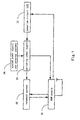
- Fig. 1 is a schematic block diagram of a notebook computer with a built-in WAN module according to the present invention.
- the notebook computer of the present invention comprises a built-in WAN module 11, an power-on circuit (EC) 12, a switching power supply (power supply control chip) 13, a system power supply and external battery 14 and a notebook system 15.
- the notebook system 15 includes hardware of a standard configuration of the notebook computer and associated software and receives information from a network through the WAN module 11.
- the notebook computer's own power supply can be used, that is, the external AC power or battery in the above system power supply and external battery 14.
- the system power supply and external battery 14 supplies power to the WAN module 11 via the switching power supply 13. This consumes only a very small amount of power.
- the notebook computer When powered on, the notebook computer supplies power to the WAN module 11 via the switching power supply 13 by using the power supply in the system power supply and external battery 14.
- the external battery can be charged when there is an external AC power supply.
- the power-on circuit 12 sends an activation signal "Enable" to the switching power supply 13 upon the detection of a signal from the WAN module 11.
- the switching power supply 13 uses the system power supply and external battery 14 to supply power to the notebook system 15 for activation of a power-on/sleep recovery mode, and, on the other hand, use the system power supply and external battery 14 to power the WAN module 11.
- the notebook system 15 when the notebook computer is in the power-on state, the notebook system 15 is connected to the WAN module 11 via a data interface, and transmits or acquires information over the network through the WAN module.
- the WAN module 11 is powered on only after a SIM card has been inserted into the WAN module 11.
- the card inserting slot for inserting a SIM card can be connected to the power-on circuit 12 via a GPIO port.
- the power-on circuit 12 sends the activation signal "Enable" to activate the switching power supply 13. Having been activated, the switching power supply 13 applies the voltage of the system power supply and external battery 14 to the WAN module 11 to power it on.
- the power-on circuit 12 sends a non-activation signal "Disable" to the switching power supply 13 upon no detection of an inserted SIM card. Since the switching power supply 13 is not activated, it cannot apply the voltage of the system power supply and external battery 14 to the WAN module 11. In this way, effect of power saving can be achieved.
- the WAN module 11 (with a SIM card inserted in), which is in the operating state while a call is coming in, receives the incoming call, a register of the processor in the WAN module 11 is changed, and thus the level of the corresponding state pin is also changed. If the state pin is connected to the power-on circuit 12 via a GPIO port, the level change of the state pin can be detected by the power-on circuit 12. The power-on circuit 12 sends the activation signal "Enable" to the switching power supply 13 when it detects the level change of the state pin.
- the switching power supply 13 uses the system power supply and external battery 14 to supply power to the notebook system 15 for activation of a power-on/sleep recovery mode, and, on the other hand, use the system power supply and external battery 14 to power the WAN module 11.
- the GPIO interface is suspended, and any message from the GPIO is not processed until the notebook computer enters the power-off/sleep state again.
- the notebook computer Having been in the operating state, the notebook computer will quickly activate communication software of the operating system and conduct voice and data exchange tasks through the WAN module 11 and the wireless network.
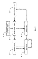
- Fig. 2 is a schematic block diagram of a notebook computer with an externally-built WAN module according to the present invention.
- the notebook computer of the present invention comprises an externally-built WAN module 11, a power-on circuit 12, a switching power supply 13, a system power supply and external battery 14, a notebook system 15 and a sensor circuit 16.
- the notebook system 15 includes hardware of a standard configuration of the notebook computer and associated software and receives information from a network through the WAN module 11.
- the WAN module 11 To enable the WAN module 11 to receive incoming information from the communication network in the power-off/sleep state of the notebook computer, it is necessary to supply power to the WAN module 11 even after the computer enters the power-off/sleep state and thus to keep the WAN module 11 in a normal operating state.
- the notebook computer's own power supply can be used, that is, the power in above system power supply and external battery 14.
- the system power supply and external battery 14 supplies power to the sensor circuit 16 and the WAN module 11 via the switching power supply 13, This consumes only a very small amount of power.
- the notebook computer When powered on, the notebook computer supplies power to the WAN module 11 via the switching power supply 13 and the sensor circuit 16 by using the power supply in the system power supply and external battery 14.
- the power-on circuit 12 sends an activation signal "Enable" to the switching power supply 13 upon the detection of a signal from the WAN module 11.
- the switching power supply 13 uses the system power supply and external battery 14 to supply power to the notebook system 15 for activation of a power-on/sleep recovery mode, and, on the other hand, uses the system power supply and external battery 14 to power the WAN module 11.
- the notebook system 15 when the notebook computer is in the power-on state, the notebook system 15 is connected to the WAN module 11 via a data interface, and transmits or acquires information over the network through the WAN module.
- the WAN module 11 is powered on only after a SIM card has been inserted into the WAN module 11, as the case of a built-in WAN module.
- the WAN module 11 with a SIM card inserted is connected to the power-on circuit 12 via a GPIO port.
- the power-on circuit 12 sends the activation signal "Enable" to activate the switching power supply 13. Having been activated, the switching power supply 13 applies the voltage of the system power supply and external battery 14 to the WAN module 11 to power it on.
- the power-on circuit 12 sends a non-activation signal "Disable" to the switching power supply 13 upon no detection of an inserted SIM card. Since the switching power supply 13 is not activated, it cannot apply the voltage of the system power supply and external battery 14 to the WAN module 11. In this way, effect of power saving can be achieved.
- the power of the WAN module 11 varies a lot between an activation state and an idle state, when it is answering a phone call/receiving a short message. Therefore, the two states can be discriminated accordingly.
- the WAN module 11 consumes about 80mA in the idle mode, while the operating current ranges from 350 to 450mA when a phone call is received. Therefore, the sensor circuit 16 is used to detect the operating current of the WAN module 11 in the present invention.
- the sensor circuit 16 Power Switch chip
- the sensor circuit 16 can detect a current of 250mA. When the current flowing through the sensor circuit 16 exceeds 250mA, its pin OC# sends out a low level warning that the current is now below 250mA.
- the pin OC# can be connected to the power-on circuit 12 via a GPIO port, and its state change can be detected by the power-on circuit 12.
- the power-on circuit 12 Upon detection of the low level, the power-on circuit 12 starts the power-on/sleep recovery mode for the notebook computer. Meanwhile, the GPIO port is suspended and its register bit is masked to prevent false power-on, until the notebook computer is in the power- off/sleep state again.
- the widely-used module includes a Cardbus card (32bit), for example.
- Cardbus card 32bit
- the event of an incoming call from outside can cause a change in the signal of the Cardbus card when the Carbus is powered normally.
- such change can be detected by the power-on circuit 12 so as to wake up the notebook computer from the power-off/sleep state.
- the notebook computer After being waken up, the notebook computer will quickly perform communication software of the operating system and conduct voice and data exchange tasks with the outside.
- the notebook computer can be designed as a two-screen notebook computer, in which a small liquid crystal screen is provided on the upper cover.
- the power-on circuit activates the system of the small liquid crystal screen and emits a ring for user notification. In this way, the user can use this system to communicate with the outside world.
- BIOS dedicated to wake up the notebook computer
- only the hardware associated with network communication content needs to be initialized after the wakeup of the notebook computer.
- the notebook computer can quickly enter the operating system and launch a communication interface to exchange voice and data with the outside.
- the notebook computer of the present invention is capable of receiving network information in real time.
- the instant messaging software including QQ, phone call answering, SMS transmission and reception, etc, can be started at any moment to conduct network communication.
- the notebook computer can be awakened remotely. Only the hardware associated with the current service needs to be started at the time of power-on. And the notebook computer is powered off automatically after the task is fulfilled.
- the host computer can be awakened at any moment to send/receive mails. When the computer receives an incoming call and nobody answers it, it is possible to enter an audio recording system, to forward the call or to forward the received short message and phone number.
- a local PC can be called, and a telephone conference can be held through SKYPE, QQ or MSN, which saves cost for long-distance phone.
- a short-message customization task can be used after the system is woken up.
Landscapes
- Engineering & Computer Science (AREA)
- Theoretical Computer Science (AREA)
- Physics & Mathematics (AREA)
- General Engineering & Computer Science (AREA)
- General Physics & Mathematics (AREA)
- Computer Networks & Wireless Communication (AREA)
- Signal Processing (AREA)
- Power Sources (AREA)
- Mobile Radio Communication Systems (AREA)
- Telephone Function (AREA)
- Telephonic Communication Services (AREA)
Abstract
Description
- The present invention relates to the field of computer technology, and in particular to a notebook computer.
- Nowadays, the emergence of GPRS, CDMA and 3G technologies further facilitates the connection between notebook computers and the Internet. To enable mobile access to network, SMS transmission and reception, phone calling and the like with a notebook computer, what is required is only inserting a communication card (i.e., WAN module, such as GPRS, CDMA or 3G wireless network card) into an interface (e.g., USB or Cardbus) of the notebook computer.
- After access to the network and surfing the Internet by means of a WAN module, a user usually leaves his or her SIM card in the WAN module while the notebook computer enters a power-off state or a sleep state. In this case, if there is information (e.g., phone call or short message) sent from a wireless network, such as GPRS or CDMA network, the user can not receive such information.
- For the conventional notebook computer, the WAN module is not provided with power if the computer is in a power-off state or sleep state, and thus all operations associated with the WAN module are un-activated. Even when the WAN module has been supplied with power, such events as powering on or waking up the computer cannot be effected.
- The object of the present invention is to provide a notebook computer capable of performing online network communication at any time.
- The notebook computer of the present invention comprises a network communication module, a power-on circuit, a switching power supply, a system power supply and external battery and a notebook system. The system power supply and external battery constantly supplies power to the network communication module by using an external AC power supply or a battery, when the notebook computer is in a power-off/sleep state. When the power-on circuit detects that the network communication module has received information from a network, it activates the switching power supply to supply power to the notebook computer and thus put the notebook computer into an operating state.
- The advantages of the present invention is that, by supplying power to the network communication module in the power-off/sleep state of the notebook computer, the computer can be in the network communication state at any time and thus will not miss any information, including incoming call or short message, transmitted over the network.
-
-
Fig. 1 is a schematic block diagram of a notebook computer with a built-in WAN module according to the present invention; and -
Fig. 2 is a schematic block diagram of a notebook computer with an externally-built WAN module according to the present invention. - Now, an explanation will be made to a notebook computer of the present invention in connection with the figures.
-
Fig. 1 is a schematic block diagram of a notebook computer with a built-in WAN module according to the present invention. - As shown in
Fig. 1 , the notebook computer of the present invention comprises a built-inWAN module 11, an power-on circuit (EC) 12, a switching power supply (power supply control chip) 13, a system power supply andexternal battery 14 and anotebook system 15. Thenotebook system 15 includes hardware of a standard configuration of the notebook computer and associated software and receives information from a network through theWAN module 11. - To enable the
WAN module 11 to receive information from the communication network in the power-off/sleep state of the notebook computer, it is necessary to supply power to theWAN module 11 even after the computer device enters the power-off/sleep state and thus to keep theWAN module 11 in a normal operating state. - As one of the simplest schemes for acquiring power supply, the notebook computer's own power supply can be used, that is, the external AC power or battery in the above system power supply and
external battery 14. When the notebook computer has been turned off, the system power supply andexternal battery 14 supplies power to theWAN module 11 via theswitching power supply 13. This consumes only a very small amount of power. - When powered on, the notebook computer supplies power to the
WAN module 11 via theswitching power supply 13 by using the power supply in the system power supply andexternal battery 14. The external battery can be charged when there is an external AC power supply. Specifically, the power-oncircuit 12 sends an activation signal "Enable" to theswitching power supply 13 upon the detection of a signal from theWAN module 11. Theswitching power supply 13, on one hand, uses the system power supply andexternal battery 14 to supply power to thenotebook system 15 for activation of a power-on/sleep recovery mode, and, on the other hand, use the system power supply andexternal battery 14 to power theWAN module 11. - In
Fig. 1 , when the notebook computer is in the power-on state, thenotebook system 15 is connected to theWAN module 11 via a data interface, and transmits or acquires information over the network through the WAN module. - Below, a detailed description will be given to the power-on/sleep recovery process of the notebook computer shown in
Fig. 1 . - For a built-in WAN module in the present invention, the
WAN module 11 is powered on only after a SIM card has been inserted into theWAN module 11. Thus, the card inserting slot for inserting a SIM card can be connected to the power-oncircuit 12 via a GPIO port. When detecting that a SIM card has been inserted into theWAN module 11 via the GPIO port, the power-oncircuit 12 sends the activation signal "Enable" to activate theswitching power supply 13. Having been activated, theswitching power supply 13 applies the voltage of the system power supply andexternal battery 14 to theWAN module 11 to power it on. On the other hand, the power-oncircuit 12 sends a non-activation signal "Disable" to the switchingpower supply 13 upon no detection of an inserted SIM card. Since theswitching power supply 13 is not activated, it cannot apply the voltage of the system power supply andexternal battery 14 to theWAN module 11. In this way, effect of power saving can be achieved. - There are a variety of known WAN modules and interfaces, among which the commonly-used interfaces include PCMCIA, USB, PCI interface, etc. When the notebook computer stays in the power-off/sleep state, the system power supply and
external battery 14 needs to provide power to these interfaces so that the WAN module can be kept in the operating state. At this moment, a user can hear a ring indicating that a call is established if he or she makes a phone call to theWAN module 11. - Particularly, after the WAN module 11 (with a SIM card inserted in), which is in the operating state while a call is coming in, receives the incoming call, a register of the processor in the
WAN module 11 is changed, and thus the level of the corresponding state pin is also changed. If the state pin is connected to the power-oncircuit 12 via a GPIO port, the level change of the state pin can be detected by the power-oncircuit 12. The power-oncircuit 12 sends the activation signal "Enable" to the switchingpower supply 13 when it detects the level change of the state pin. Theswitching power supply 13, on one hand, uses the system power supply andexternal battery 14 to supply power to thenotebook system 15 for activation of a power-on/sleep recovery mode, and, on the other hand, use the system power supply andexternal battery 14 to power theWAN module 11. After the notebook computer has entered the power-on state, the GPIO interface is suspended, and any message from the GPIO is not processed until the notebook computer enters the power-off/sleep state again. - Having been in the operating state, the notebook computer will quickly activate communication software of the operating system and conduct voice and data exchange tasks through the
WAN module 11 and the wireless network. -
Fig. 2 is a schematic block diagram of a notebook computer with an externally-built WAN module according to the present invention. - As shown in
Fig. 2 , the notebook computer of the present invention comprises an externally-builtWAN module 11, a power-oncircuit 12, aswitching power supply 13, a system power supply andexternal battery 14, anotebook system 15 and asensor circuit 16. Thenotebook system 15 includes hardware of a standard configuration of the notebook computer and associated software and receives information from a network through theWAN module 11. - To enable the
WAN module 11 to receive incoming information from the communication network in the power-off/sleep state of the notebook computer, it is necessary to supply power to theWAN module 11 even after the computer enters the power-off/sleep state and thus to keep theWAN module 11 in a normal operating state. - As one of the simplest schemes for acquiring power supply, the notebook computer's own power supply can be used, that is, the power in above system power supply and
external battery 14. When the notebook computer has been shut down, the system power supply andexternal battery 14 supplies power to thesensor circuit 16 and theWAN module 11 via theswitching power supply 13, This consumes only a very small amount of power. - When powered on, the notebook computer supplies power to the
WAN module 11 via theswitching power supply 13 and thesensor circuit 16 by using the power supply in the system power supply andexternal battery 14. Specifically, the power-oncircuit 12 sends an activation signal "Enable" to theswitching power supply 13 upon the detection of a signal from theWAN module 11. Theswitching power supply 13, on one hand, uses the system power supply andexternal battery 14 to supply power to thenotebook system 15 for activation of a power-on/sleep recovery mode, and, on the other hand, uses the system power supply andexternal battery 14 to power theWAN module 11. - In
Fig. 2 , when the notebook computer is in the power-on state, thenotebook system 15 is connected to theWAN module 11 via a data interface, and transmits or acquires information over the network through the WAN module. - Below, a detailed description will be given to the power-on/sleep recovery process of the notebook computer shown in
Fig. 2 . - For an externally-built WAN module in the present invention, the
WAN module 11 is powered on only after a SIM card has been inserted into theWAN module 11, as the case of a built-in WAN module. Thus, theWAN module 11 with a SIM card inserted is connected to the power-oncircuit 12 via a GPIO port. When detecting via the GPIO port that a SIM card has been inserted into theWAN module 11, the power-oncircuit 12 sends the activation signal "Enable" to activate theswitching power supply 13. Having been activated, theswitching power supply 13 applies the voltage of the system power supply andexternal battery 14 to theWAN module 11 to power it on. On the other hand, the power-oncircuit 12 sends a non-activation signal "Disable" to the switchingpower supply 13 upon no detection of an inserted SIM card. Since the switchingpower supply 13 is not activated, it cannot apply the voltage of the system power supply andexternal battery 14 to theWAN module 11. In this way, effect of power saving can be achieved. - For the externally-built WAN module, the power of the
WAN module 11 varies a lot between an activation state and an idle state, when it is answering a phone call/receiving a short message. Therefore, the two states can be discriminated accordingly. - As shown in experimental results, the
WAN module 11 consumes about 80mA in the idle mode, while the operating current ranges from 350 to 450mA when a phone call is received. Therefore, thesensor circuit 16 is used to detect the operating current of theWAN module 11 in the present invention. As an example, the sensor circuit 16 (Power Switch chip) can detect a current of 250mA. When the current flowing through thesensor circuit 16 exceeds 250mA, its pin OC# sends out a low level warning that the current is now below 250mA. The pin OC# can be connected to the power-oncircuit 12 via a GPIO port, and its state change can be detected by the power-oncircuit 12. Upon detection of the low level, the power-oncircuit 12 starts the power-on/sleep recovery mode for the notebook computer. Meanwhile, the GPIO port is suspended and its register bit is masked to prevent false power-on, until the notebook computer is in the power- off/sleep state again. - There are many types of known WAN modules, among which the widely-used module includes a Cardbus card (32bit), for example. There is a state change signal among the bus signals of the Cardbus card. The event of an incoming call from outside can cause a change in the signal of the Cardbus card when the Carbus is powered normally. In the present invention, such change can be detected by the power-on
circuit 12 so as to wake up the notebook computer from the power-off/sleep state. - After being waken up, the notebook computer will quickly perform communication software of the operating system and conduct voice and data exchange tasks with the outside.
- In both of the above cases, the notebook computer can be designed as a two-screen notebook computer, in which a small liquid crystal screen is provided on the upper cover. When a phone call/short message has come in, the power-on circuit activates the system of the small liquid crystal screen and emits a ring for user notification. In this way, the user can use this system to communicate with the outside world.
- Further, by customizing a BIOS dedicated to wake up the notebook computer, only the hardware associated with network communication content needs to be initialized after the wakeup of the notebook computer. In this way, the notebook computer can quickly enter the operating system and launch a communication interface to exchange voice and data with the outside.
- As can been seen from the foregoing description, the notebook computer of the present invention is capable of receiving network information in real time. Thus, with the WAN module being always online, the instant messaging software, including QQ, phone call answering, SMS transmission and reception, etc, can be started at any moment to conduct network communication. The notebook computer can be awakened remotely. Only the hardware associated with the current service needs to be started at the time of power-on. And the notebook computer is powered off automatically after the task is fulfilled. Further, with the WAN module being always online, the host computer can be awakened at any moment to send/receive mails. When the computer receives an incoming call and nobody answers it, it is possible to enter an audio recording system, to forward the call or to forward the received short message and phone number. In addition, a local PC can be called, and a telephone conference can be held through SKYPE, QQ or MSN, which saves cost for long-distance phone. Also, a short-message customization task can be used after the system is woken up.
- The application of the present invention to a wireless network has been explained in the above description with reference to
Figs. 1 and2 . It can be appreciated that the present invention can also be applicable to a wired network. In this case, the only difference is to replace the WAN module with a wired network adapter, which is supplied with power in the same manner as that for the WAN module. The rest of the overall processing is identical, and description thereof is omitted. - The present invention is not limited to the above embodiments. Any modification, change or substitution readily made by those ordinarily skilled in the art after reading the application shall fall into the scope defined by the claims of the present invention.
Claims (7)
- A notebook computer comprising a network communication module, a power-on circuit, a switching power supply, a system power supply and external battery and a notebook system, wherein
the system power supply and external battery constantly supplies power to the network communication module by using an external AC power supply or power of the battery , when the notebook computer is in a power-off/sleep state, and
when the power-on circuit detects that the network communication module has received information from a network, it activates the switching power supply to supply power to the notebook computer and thus put the notebook computer into an operating state. - The notebook computer according to Claim 1, wherein the system power supply and external battery supplies power to the network communication module by using a power supply contained in the system power supply and external battery, when the notebook computer is in the operating state.
- The notebook computer according to Claim 1 or 2, wherein said network communication module comprises a WAN module or a wired network adapter.
- The notebook computer according to Claim 3, wherein the WAN module is connected to the power-on circuit via a GPIO port,
when detecting the insertion of a SIM card, the power-on circuit activates the switching power supply and supplies power to the WAN module by using the external AC power supply of the system power supply and external battery or power of the battery. - The notebook computer according to Claim 4, wherein, when detecting that the WAN module has received information from a network, the power-on circuit activates the switching power supply, and the switching power supply starts up the notebook system, and
the GPIO port is suspended after the notebook computer is in a power-on state. - The notebook computer according to Claim 4, further comprising a sensor circuit,
wherein the sensor circuit provides the system power supply and external battery to the WAN module,
when detecting that the WAN module has received information from a network, the sensor circuit outputs the detection result to the power-on circuit via a GPIO port,
the power-on circuit activates the switching power supply based on the detection result, and the switching power supply starts up the notebook system, and the GPIO port is suspended after the notebook computer enters a power-on state. - The notebook computer according to Claim 6, wherein the sensor circuit determines whether the WAN module has received information from a network by detecting the operating current of the WAN module.
Applications Claiming Priority (2)
| Application Number | Priority Date | Filing Date | Title |
|---|---|---|---|
| CN200510132999A CN1991683B (en) | 2005-12-31 | 2005-12-31 | a laptop |
| PCT/CN2006/000479 WO2007076645A1 (en) | 2005-12-31 | 2006-03-23 | Notebook computer |
Publications (2)
| Publication Number | Publication Date |
|---|---|
| EP1973026A1 true EP1973026A1 (en) | 2008-09-24 |
| EP1973026A4 EP1973026A4 (en) | 2010-08-18 |
Family
ID=38213975
Family Applications (1)
| Application Number | Title | Priority Date | Filing Date |
|---|---|---|---|
| EP06722131A Ceased EP1973026A4 (en) | 2005-12-31 | 2006-03-23 | Notebook computer |
Country Status (4)
| Country | Link |
|---|---|
| US (1) | US8046610B2 (en) |
| EP (1) | EP1973026A4 (en) |
| CN (1) | CN1991683B (en) |
| WO (1) | WO2007076645A1 (en) |
Cited By (4)
| Publication number | Priority date | Publication date | Assignee | Title |
|---|---|---|---|---|
| EP2339815A1 (en) * | 2009-12-23 | 2011-06-29 | Intel Corporation | Remote management over a wireless wide-area network using short message service |
| EP2648109A1 (en) * | 2012-04-02 | 2013-10-09 | BlackBerry Limited | Hot swapping swap media at a computing device |
| US8996776B2 (en) | 2012-04-02 | 2015-03-31 | Blackberry Limited | Computing device and method for hot swapping media |
| TWI501672B (en) * | 2009-11-25 | 2015-09-21 | Hewlett Packard Development Co | Radio device |
Families Citing this family (6)
| Publication number | Priority date | Publication date | Assignee | Title |
|---|---|---|---|---|
| US8571604B2 (en) * | 2008-01-18 | 2013-10-29 | Hewlett-Packard Development Company, L.P. | Subscriber identity module (SIM) card access system and method |
| US8127126B2 (en) * | 2009-10-06 | 2012-02-28 | Li-Chun Lai | Integrated power supply and network connection control device for cord set |
| CN101790225A (en) * | 2010-03-16 | 2010-07-28 | 华为终端有限公司 | Power management method and device for on-line module |
| JP2012242949A (en) * | 2011-05-17 | 2012-12-10 | Sony Corp | Information processing device and method, recording medium, and program |
| TWI488519B (en) * | 2012-01-13 | 2015-06-11 | 宏碁股份有限公司 | Wireless communication device |
| CN103294156B (en) * | 2012-02-24 | 2016-03-02 | 联想(北京)有限公司 | On-line Control device, control method and digital processing device at any time |
Family Cites Families (17)
| Publication number | Priority date | Publication date | Assignee | Title |
|---|---|---|---|---|
| CN1157957A (en) * | 1995-09-19 | 1997-08-27 | 北京九州计算机网络公司 | Method and device for personal computer green communication |
| US6311282B1 (en) * | 1996-02-27 | 2001-10-30 | Fujitsu Personal Systems, Inc. | Method and apparatus for computing device with status display |
| CN2558008Y (en) * | 2000-05-31 | 2003-06-25 | 庞剑 | Digital mobile telecommunication computer |
| US6760850B1 (en) * | 2000-07-31 | 2004-07-06 | Hewlett-Packard Development Company, L.P. | Method and apparatus executing power on self test code to enable a wakeup device for a computer system responsive to detecting an AC power source |
| US6687348B2 (en) * | 2001-11-16 | 2004-02-03 | International Business Machines Corporation | Method and system for conserving power and improving usability for personal computers with remote startup features |
| JP2003195989A (en) * | 2001-12-26 | 2003-07-11 | Internatl Business Mach Corp <Ibm> | Computer device, power source supply control method and program |
| JP2004038295A (en) * | 2002-06-28 | 2004-02-05 | Toshiba Corp | Information processing apparatus and power control method |
| US8707406B2 (en) * | 2002-07-26 | 2014-04-22 | Sierra Wireless, Inc. | Always-on virtual private network access |
| JP4095501B2 (en) * | 2003-06-25 | 2008-06-04 | インターナショナル・ビジネス・マシーンズ・コーポレーション | Computer apparatus, wireless access point, power-on method via wireless network, frame listening method, frame transmission method, and program |
| CN100512167C (en) * | 2003-07-14 | 2009-07-08 | 中兴通讯股份有限公司 | Device and method for realizing computer wireless connection to Internet under mobile environment |
| CN100378617C (en) | 2003-09-09 | 2008-04-02 | 华宇电脑股份有限公司 | Network awakening device and method |
| US20050085245A1 (en) * | 2003-10-15 | 2005-04-21 | Danneels Gunner D. | Wake of computer system on reception of short message service (SMS) |
| US7231533B2 (en) * | 2003-12-23 | 2007-06-12 | Microchip Technology Incorporated | Wake-up reset circuit draws no current when a control signal indicates sleep mode for a digital device |
| FR2864648B1 (en) * | 2003-12-31 | 2006-02-24 | Radiotelephone Sfr | METHOD OF ALARMING AN AUTONOMOUS COMPUTER |
| TWI273789B (en) * | 2004-02-24 | 2007-02-11 | Via Tech Inc | Method for adjusting the power consumption of a network interface |
| US8576758B2 (en) * | 2006-09-29 | 2013-11-05 | Lenovo (Beijing) Limited | Remote wake-up system, WWAM module and terminal |
| US9265003B2 (en) * | 2006-11-13 | 2016-02-16 | Qualcomm Incorporated | Apparatus and methods for reducing power consumption and/or radio frequency interference in a mobile computing device |
-
2005
- 2005-12-31 CN CN200510132999A patent/CN1991683B/en not_active Expired - Lifetime
-
2006
- 2006-03-23 US US12/159,583 patent/US8046610B2/en active Active
- 2006-03-23 WO PCT/CN2006/000479 patent/WO2007076645A1/en not_active Ceased
- 2006-03-23 EP EP06722131A patent/EP1973026A4/en not_active Ceased
Cited By (8)
| Publication number | Priority date | Publication date | Assignee | Title |
|---|---|---|---|---|
| TWI501672B (en) * | 2009-11-25 | 2015-09-21 | Hewlett Packard Development Co | Radio device |
| US9655044B2 (en) | 2009-11-25 | 2017-05-16 | Hewlett-Packard Development Company, L.P. | Radio device |
| US10524208B2 (en) | 2009-11-25 | 2019-12-31 | Hewlett-Packard Development Company, L.P. | Controlling an amount of power supplied to a radio device |
| EP2339815A1 (en) * | 2009-12-23 | 2011-06-29 | Intel Corporation | Remote management over a wireless wide-area network using short message service |
| US8195146B2 (en) | 2009-12-23 | 2012-06-05 | Intel Corporation | Remote management over a wireless wide-area network using short message service |
| US8688104B2 (en) | 2009-12-23 | 2014-04-01 | Intel Corporation | Remote management over a wireless wide-area network using short message service |
| EP2648109A1 (en) * | 2012-04-02 | 2013-10-09 | BlackBerry Limited | Hot swapping swap media at a computing device |
| US8996776B2 (en) | 2012-04-02 | 2015-03-31 | Blackberry Limited | Computing device and method for hot swapping media |
Also Published As
| Publication number | Publication date |
|---|---|
| CN1991683A (en) | 2007-07-04 |
| EP1973026A4 (en) | 2010-08-18 |
| US8046610B2 (en) | 2011-10-25 |
| US20090307506A1 (en) | 2009-12-10 |
| WO2007076645A1 (en) | 2007-07-12 |
| CN1991683B (en) | 2010-05-05 |
Similar Documents
| Publication | Publication Date | Title |
|---|---|---|
| US8001406B2 (en) | Method and apparatus for managing power of portable information device | |
| US20110307727A1 (en) | Computer with Built-in Wireless Module and Standby and Activate Method Thereof | |
| US20100115150A1 (en) | Information processor | |
| US8340721B2 (en) | Notebook computer and cell phone assembly | |
| US10007316B2 (en) | State control method and apparatus and portable terminal | |
| US8046610B2 (en) | Power supply control in a mobile portable device | |
| CN105100730A (en) | Monitoring method and camera device | |
| CN101790225A (en) | Power management method and device for on-line module | |
| US7502635B1 (en) | Method and computer for remote communication while operating in a power-saving mode | |
| US7206603B2 (en) | Cellular radio telephone set | |
| US7571332B2 (en) | Reducing power consumed by a computer system during a hibernation or an off state by remotely waking up the computer system | |
| US20130346737A1 (en) | Method for remotely powering on host and system and electronic apparatus using the method | |
| US20080253357A1 (en) | Computer system with internet phone functionality | |
| US6877058B2 (en) | Information processing unit having a slot, information processing method for an information processing unit, and program that controls an information processing unit | |
| US20100077235A1 (en) | Mobile communication device and controlling method thereof | |
| US7884885B2 (en) | Power control method used with TV module of portable electronic apparatus | |
| CN111026684B (en) | Interface control method, interface control device and storage medium | |
| CN101373399B (en) | Electronic device with mobile communication and control method thereof | |
| CN103685764A (en) | Power-saving method for mobile terminal and device | |
| US20100037074A1 (en) | Power control for serial bus peripheral device | |
| CN114924639A (en) | Electronic device and method for waking up micro control unit | |
| US20060052079A1 (en) | Method for controlling the power consumption in an electronic appliance | |
| CN211454606U (en) | Electronics and Terminal Equipment | |
| CN109445566B (en) | OTG (on-the-go) power-saving processing method and system, storage medium and mobile terminal | |
| KR100605962B1 (en) | Combined portable terminal device and method for controlling data transmission and reception between mobile phone and personal information terminal |
Legal Events
| Date | Code | Title | Description |
|---|---|---|---|
| PUAI | Public reference made under article 153(3) epc to a published international application that has entered the european phase |
Free format text: ORIGINAL CODE: 0009012 |
|
| 17P | Request for examination filed |
Effective date: 20080728 |
|
| AK | Designated contracting states |
Kind code of ref document: A1 Designated state(s): DE FR GB |
|
| DAX | Request for extension of the european patent (deleted) | ||
| RBV | Designated contracting states (corrected) |
Designated state(s): DE FR GB |
|
| A4 | Supplementary search report drawn up and despatched |
Effective date: 20100716 |
|
| 17Q | First examination report despatched |
Effective date: 20110328 |
|
| REG | Reference to a national code |
Ref country code: DE Ref legal event code: R003 |
|
| STAA | Information on the status of an ep patent application or granted ep patent |
Free format text: STATUS: THE APPLICATION HAS BEEN REFUSED |
|
| 18R | Application refused |
Effective date: 20120508 |