EP1972873A1 - An appliance and a method for a built-in arrangement in a kitchen interior - Google Patents
An appliance and a method for a built-in arrangement in a kitchen interior Download PDFInfo
- Publication number
- EP1972873A1 EP1972873A1 EP08003847A EP08003847A EP1972873A1 EP 1972873 A1 EP1972873 A1 EP 1972873A1 EP 08003847 A EP08003847 A EP 08003847A EP 08003847 A EP08003847 A EP 08003847A EP 1972873 A1 EP1972873 A1 EP 1972873A1
- Authority
- EP
- European Patent Office
- Prior art keywords
- appliance
- plinth
- kitchen interior
- panel
- kitchen
- Prior art date
- Legal status (The legal status is an assumption and is not a legal conclusion. Google has not performed a legal analysis and makes no representation as to the accuracy of the status listed.)
- Ceased
Links
- 238000000034 method Methods 0.000 title claims abstract description 11
- 238000001816 cooling Methods 0.000 claims description 6
- 238000009429 electrical wiring Methods 0.000 claims description 5
- 239000002184 metal Substances 0.000 claims description 5
- 238000004873 anchoring Methods 0.000 description 4
- 230000000694 effects Effects 0.000 description 4
- 238000005192 partition Methods 0.000 description 4
- 238000009413 insulation Methods 0.000 description 2
- 239000000203 mixture Substances 0.000 description 2
- 238000005452 bending Methods 0.000 description 1
- 238000006073 displacement reaction Methods 0.000 description 1
- 235000013305 food Nutrition 0.000 description 1
- 238000009434 installation Methods 0.000 description 1
- 238000004519 manufacturing process Methods 0.000 description 1
Images




Classifications
-
- F—MECHANICAL ENGINEERING; LIGHTING; HEATING; WEAPONS; BLASTING
- F25—REFRIGERATION OR COOLING; COMBINED HEATING AND REFRIGERATION SYSTEMS; HEAT PUMP SYSTEMS; MANUFACTURE OR STORAGE OF ICE; LIQUEFACTION SOLIDIFICATION OF GASES
- F25D—REFRIGERATORS; COLD ROOMS; ICE-BOXES; COOLING OR FREEZING APPARATUS NOT OTHERWISE PROVIDED FOR
- F25D23/00—General constructional features
- F25D23/10—Arrangements for mounting in particular locations, e.g. for built-in type, for corner type
-
- F—MECHANICAL ENGINEERING; LIGHTING; HEATING; WEAPONS; BLASTING
- F25—REFRIGERATION OR COOLING; COMBINED HEATING AND REFRIGERATION SYSTEMS; HEAT PUMP SYSTEMS; MANUFACTURE OR STORAGE OF ICE; LIQUEFACTION SOLIDIFICATION OF GASES
- F25D—REFRIGERATORS; COLD ROOMS; ICE-BOXES; COOLING OR FREEZING APPARATUS NOT OTHERWISE PROVIDED FOR
- F25D23/00—General constructional features
- F25D23/003—General constructional features for cooling refrigerating machinery
-
- F—MECHANICAL ENGINEERING; LIGHTING; HEATING; WEAPONS; BLASTING
- F25—REFRIGERATION OR COOLING; COMBINED HEATING AND REFRIGERATION SYSTEMS; HEAT PUMP SYSTEMS; MANUFACTURE OR STORAGE OF ICE; LIQUEFACTION SOLIDIFICATION OF GASES
- F25D—REFRIGERATORS; COLD ROOMS; ICE-BOXES; COOLING OR FREEZING APPARATUS NOT OTHERWISE PROVIDED FOR
- F25D2323/00—General constructional features not provided for in other groups of this subclass
- F25D2323/002—Details for cooling refrigerating machinery
- F25D2323/0026—Details for cooling refrigerating machinery characterised by the incoming air flow
- F25D2323/00264—Details for cooling refrigerating machinery characterised by the incoming air flow through the front bottom part
-
- F—MECHANICAL ENGINEERING; LIGHTING; HEATING; WEAPONS; BLASTING
- F25—REFRIGERATION OR COOLING; COMBINED HEATING AND REFRIGERATION SYSTEMS; HEAT PUMP SYSTEMS; MANUFACTURE OR STORAGE OF ICE; LIQUEFACTION SOLIDIFICATION OF GASES
- F25D—REFRIGERATORS; COLD ROOMS; ICE-BOXES; COOLING OR FREEZING APPARATUS NOT OTHERWISE PROVIDED FOR
- F25D2323/00—General constructional features not provided for in other groups of this subclass
- F25D2323/002—Details for cooling refrigerating machinery
- F25D2323/0027—Details for cooling refrigerating machinery characterised by the out-flowing air
- F25D2323/00274—Details for cooling refrigerating machinery characterised by the out-flowing air from the front bottom
Definitions
- the invention relates to an appliance, such as a refrigerator or a freezer, which is adapted for a built-in arrangement into a kitchen interior by positioning into an opening in the kitchen interior, the appliance having a door being adapted to support a front door panel in alignment with other cabinet doors of the kitchen interior.
- an appliance such as a refrigerator or a freezer
- the invention also relates to a method for mounting such an appliance in a built-in arrangement into a kitchen interior.
- built-in appliances such as refrigerators and freezers
- Built-in appliances are arranged in kitchen furniture and has a special door adapted to support a front door panel which usually has the same appearance as and is aligned with the other cabinet doors of the kitchen interior. In that way built-in appliances blend with the rest of the kitchen interior and gives the kitchen a modern and uniform look.
- a built-in appliance is placed and mounted in a kitchen interior such that the body of the appliance is positioned into a separate kitchen cabinet and a front door panel is connected to the door of the appliance by means of suitable connecting elements.
- the invention also relates to a method for mounting an appliance into a kitchen interior having essentially the same object as above. At least this object is achieved by a method according to claim 9.
- the basis of the invention is the insight that this object may be achieved by mounting the appliance into the kitchen interior without having a separate cabinet for the appliance. Instead, the appliance is positioned into an opening in the kitchen interior adjacent at least one adjoining kitchen cabinet and it is standing on its own base frame or feet directly on the floor. In this way the available opening space in the kitchen interior can be utilized to the maximum possible extent without any useful space being wasted for a separate kitchen cabinet.
- the appliance is provided with a setback plinth portion such that the kitchen interior can be provided with an uniform plinth panel extending over the entire length of the kitchen interior, the appliance(s) included.
- a condenser tube system in an embodiment of the invention, is not positioned in the back of the appliance as is common for refrigerators and freezers. Instead, the appliance is provided with a rear panel, preferably of a metal sheet, which is positioned as far rearward as possible towards a wall or the like behind the kitchen interior. To permit electrical wiring to lighting inside the appliance, regulation and the like, the rear panel, in one embodiment, is formed with recessed cable ducts in an outer surface to accommodate external electric wiring in the outer surface.
- the recessed cable ducts comprises, in one embodiment, at least one cable duct along a vertical edge of the rear panel at the connection to a side panel, from which one or more additional cable ducts can be branched off to a central portion of the rear panel, if required for lighting and the like, from each of which a hole may be formed to the inside of the appliance.
- cooling condenser tube system can optionally be positioned e.g. in the space above the appliance or, as in a hereinafter described and illustrated embodiment of the invention, in the setback plinth portion beneath the appliance.
- a fan is provided which draws air through air inlet openings in the plinth panel, which air passes by the condenser tube system provided in an inlet passage. After passing the fan, the air flow turns and exits through an outlet passage and air outlet openings in the plinth panel.
- the inlet passage and the outlet passage are separated by a partition wall.
- An appliance according to the invention may optionally be positioned in an opening between two cabinets in the kitchen interior, such that the appliance can be attached, by means of suitable anchoring fittings, to the cabinets on each side. It is also possible to position two or more appliances side by side, being attached to each other, in a large opening in the kitchen interior. However, the appliance can also be positioned outermost in a row of cabinets such that the appliance is attached only in one side to an adjacent cabinet. On the other side of the appliance, it is in this case preferably provided with a covering panel attached to the appliance and having a similar appearance as the rest of the kitchen interior. This way of positioning the appliance is facilitated when the appliance is in itself sufficient stable.
- the inventive appliance is therefore formed of an outer shell or casing of metal sheets, which are bent and welded together.
- the covering panel on the "free" side of the appliance may optionally be utilized to attach an adjoining kitchen worktop, a lower cabinet, an upper cabinet or the like.
- a built-in appliance according to the invention can be made such that the increased inner space, in comparison to prior art built-in appliances, can be utilized such that the same inner casings and interior fittings can be used as in a corresponding free-standing appliance.
- Fig 1 is a perspective view of one embodiment of an appliance 1 according to the invention.
- the appliance can optionally be a refrigerator or a freezer and comprises an outer casing 2 and one or more doors. In this case two doors 3 and 3', which cover a refrigerator compartment and a freezer compartment, respectively. However, it is to be understood that the appliance also may comprise only one door covering e.g. a large refrigerator or a freezer compartment.
- the appliance is adapted to stand on the floor of a kitchen on its own feet, indicated at 4 in form of adjustable threaded bolts. To allow the appliance to blend in with the rest of the kitchen interior, the appliance is provided with a set back plinth portion 5.
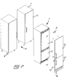
- fig 2 is illustrated how the appliance is adapted to be mounted into an opening 6 between two cabinets 7 in a kitchen interior.
- the cabinets 7 are in this case of a type standing on adjustable tubular feet 8. It is to be understood, however, that the cabinets also could be of a type standing e.g. on a box formed setback plinth portion.
- the appliance 1 is to be positioned into the opening 6 between the cabinets 7 without being positioned into a separate cabinet. Instead, the appliance has the same width as a standard cabinet and is adapted to be attached to the adjacent cabinets by means of anchoring fittings 9, such as angle bars and the like.
- the appliance 1 is adapted to be covered by front door panels 10, 10', which normally has the same appearance as cabinet doors 11 of the rest of the kitchen interior.
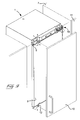
- the front door panels 10, 10' are attached to the doors 3, 3' of the appliance 1 by means of attachment fittings 12, as is best seen from the perspective view in fig 3 , such that the front door panels 10, 10' will be aligned with the cabinet doors 11 of the kitchen interior, as is illustrated in fig 4 .
- the appliance Since the doors 3, 3' of the appliance will be positioned somewhat inside in relation to the outer surfaces of the cabinet doors 11, the appliance has to be provided with a special designed hinge 13, as is shown in fig 3 , which besides effecting pivoting of the door, at the same time also effects displacement of the door outwards such that there is no risk of interference with the cabinets 7 and the cabinet doors 11 during opening of the doors 3, 3'.
- the hinge 13 also constitutes an anchoring fitting for attachment to the adjacent cabinet.
- the anchoring fittings 9, the attachment fittings 12 and the hinge 13 are well known in the prior art and will therefore not be described in detail herein.
- figs 5-7 are illustrated, in front views, a few different ways of positioning an appliance, according to the invention, in a kitchen interior.
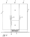
- fig 5 is illustrated the situation corresponding to fig 4 , where the appliance 1 is positioned between two tall cabinets 7.
- the cabinet doors 11 and the front door panels 10, 10' are similar, except for the size, provided with the same kind of handles 15 and aligned with each other.
- the set back plinth portions of the cabinets as well as the appliance are provided with the same kind of plinth panels 16, the only difference being that the plinth panel of the appliance is provided with an air inlet opening 17 for reasons to be explained more in detail below.
- fig 6 is illustrated an arrangement where an appliance 1 are arranged in an end of a row of tall cabinets 7 in a kitchen interior.
- the side of the appliance is covered by a panel board 18, or the like, having the same appearance as the cabinets.
- fig 7 is illustrated an arrangement where two appliances 1 are arranged in an end row of cabinets in a kitchen interior and for this reason the outermost appliance is provided with a panel board 18 on its side surface, as in the arrangement according to fig 6 .
- the cabinets of the kitchen interior which are connected to the appliance on the other side, are comprised of lower cabinets 19 being provided with a work top 20.
- the side of the appliance is covered by a panel board 18, which is utilized for attachment of the lower cabinet and the work top.
- the arrangements according to figs 6 and 7 where the appliances are not positioned between two tall cabinets, which can support the appliance, but are positioned more free-standing, is facilitated if the appliance in itself is quite rigid and stable.
- the appliance therefore is manufactured with an all-welded outer metal casing, which provides the required rigidity.
- FIG. 8 an appliance according to the invention is shown in a partly cut perspective view from behind. Since the available depth of the appliance, from the front surface of the doors 3, 3' to a rear wall or the like, is smaller for a built in appliance than for a free-standing appliance, as is mentioned before, the appliance according to the invention lacks any condenser tube system on the rear side, as is common practice for refrigerators an freezers. Instead the appliance is provided with an outer rear panel 22, which preferably is positioned as far back as the available depth permits. To accommodate electrical wiring, the rear panel 22 is provided with vertical recessed cable ducts 23 on each side portion where the rear panel is connected to each side panel 24.
- the cable ducts 23 are provided simply by bending the edge portions of the rear panel inwards. From each of the vertical cable ducts 23, laterally extending cable ducts 25 is branching off to central positions of the rear panel 22 for allowing electrical wiring through holes 26 to the inside of the appliance for lighting, sensors or the like.
- the lateral cable ducts 25 are channel formed.
- a cable tube 27 extends rearward from a control box 28 on the front side and opens through a hole 29 in the rear panel from which also lateral cable ducts 25 extend to the vertical cable ducts 23.
- the available depth for the inner refrigerator or freezer compartment will be larger than for a traditional built-in appliance.
- the available depth is so large that it is possible to use the same inner housings and interior fittings as for a free-standing appliance, despite that the space is limited on the front side since the front door panel has to be aligned with the rest of the cabinet doors in the kitchen interior.
- the tube system can, instead of being positioned on the rear side of the appliance, be positioned in the upper portion or, as in the illustrated embodiment, in the lower, setback plinth portion of the appliance.
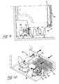
- a very compact and folded condenser tube system 30 is positioned in an inlet passage 31 of the setback plinth portion 5.
- a fan 32 is positioned in an opening in a partition plate 33 and draws, during operation, an air flow through the air inlet opening 17 in the plinth panel 16, through the condenser tube system 30 and through the hole in the partition plate 33. The air flow is then turned and flows through an outlet passage 34 on one side of the condenser tube system out of the setback plinth portion.
- the inlet and outlet passages 31 and 34 are separated by a partition wall 35.
- a compressor 36 is positioned in the rear part of the setback plinth portion 5 in the rear part of the setback plinth portion 5 in the rear part of the setback plinth portion 5 also a compressor 36 is positioned.
Landscapes
- Engineering & Computer Science (AREA)
- Chemical & Material Sciences (AREA)
- Combustion & Propulsion (AREA)
- Physics & Mathematics (AREA)
- Mechanical Engineering (AREA)
- Thermal Sciences (AREA)
- General Engineering & Computer Science (AREA)
- Refrigerator Housings (AREA)
Abstract
Description
- The invention relates to an appliance, such as a refrigerator or a freezer, which is adapted for a built-in arrangement into a kitchen interior by positioning into an opening in the kitchen interior, the appliance having a door being adapted to support a front door panel in alignment with other cabinet doors of the kitchen interior.
- The invention also relates to a method for mounting such an appliance in a built-in arrangement into a kitchen interior.
- The use of so called built-in appliances, such as refrigerators and freezers, have been more and more popular. Built-in appliances are arranged in kitchen furniture and has a special door adapted to support a front door panel which usually has the same appearance as and is aligned with the other cabinet doors of the kitchen interior. In that way built-in appliances blend with the rest of the kitchen interior and gives the kitchen a modern and uniform look. A built-in appliance is placed and mounted in a kitchen interior such that the body of the appliance is positioned into a separate kitchen cabinet and a front door panel is connected to the door of the appliance by means of suitable connecting elements.
- However, there are several drawbacks with prior art built-in appliances. The major drawback is that the inner available space in built-in appliances is considerable smaller than for a corresponding free-standing appliance occupying essentially the same overall space in the kitchen interior, which gives less storage space for foods and other products inside the appliance. The reduced inner available space has several reasons. One reason is that for a free-standing appliance, the door of the appliance is normally located outside of the plane of the cabinet doors in the kitchen interior. In a built-in appliance, on the other hand, the door must be positioned within the plain of the cabinet doors of the kitchen interior and moreover there has to be sufficient space for mounting of the front door panel on the outside such that it will be in alignment with the other cabinet doors in the kitchen interior. This has to effect that the depth of the available interior space will be smaller for a built-in appliance than for a free-standing appliance. Another reason is that, in order to let the built-in appliance blend with the remaining kitchen interior, the built-in appliance is positioned into an opening in a separate kitchen cabinet. In this way the built-in appliance can be provided with a plinth panel in the lower end just above the floor to give a uniform appearance in relation to the rest of the kitchen interior. However, this also has to effect that the available height as well as width for the appliance will be smaller. The latter since the thickness of the cabinet walls will interfere with the available space for the appliance.
- Moreover, since the inner space of a built-in appliance is smaller than a free-standing appliance, it is not possible to use the same inner casings and interior fittings for these two types of appliances. This is a disadvantage since it is more expensive to manufacture two or more separate sets of inner casings and interior fittings for essentially the same purpose, and will therefore raise the total costs for the final products.
- It is an object of the invention to overcome the drawbacks of prior art built-in appliances and provide an appliance, which presents a considerably larger inner, useful space in comparison to prior art built-in appliances occupying essentially the same space in the kitchen interior. At least this object is achieved by an appliance according to
claim 1. - The invention also relates to a method for mounting an appliance into a kitchen interior having essentially the same object as above. At least this object is achieved by a method according to
claim 9. - Accordingly, the basis of the invention is the insight that this object may be achieved by mounting the appliance into the kitchen interior without having a separate cabinet for the appliance. Instead, the appliance is positioned into an opening in the kitchen interior adjacent at least one adjoining kitchen cabinet and it is standing on its own base frame or feet directly on the floor. In this way the available opening space in the kitchen interior can be utilized to the maximum possible extent without any useful space being wasted for a separate kitchen cabinet.
- Within this general inventive idea, the invention may be modified in many different ways. In one embodiment, the appliance is provided with a setback plinth portion such that the kitchen interior can be provided with an uniform plinth panel extending over the entire length of the kitchen interior, the appliance(s) included.
- To utilize the depth of the appliance from the front door panel to a wall or the like on the rear side of the appliance, a condenser tube system, in an embodiment of the invention, is not positioned in the back of the appliance as is common for refrigerators and freezers. Instead, the appliance is provided with a rear panel, preferably of a metal sheet, which is positioned as far rearward as possible towards a wall or the like behind the kitchen interior. To permit electrical wiring to lighting inside the appliance, regulation and the like, the rear panel, in one embodiment, is formed with recessed cable ducts in an outer surface to accommodate external electric wiring in the outer surface. The recessed cable ducts comprises, in one embodiment, at least one cable duct along a vertical edge of the rear panel at the connection to a side panel, from which one or more additional cable ducts can be branched off to a central portion of the rear panel, if required for lighting and the like, from each of which a hole may be formed to the inside of the appliance. One advantage with locating at least the vertical cable duct(s) at the vertical edges or corners of the appliance, is that here the thermal insulation is as largest, which has to effect that any increased heat leakage due to the recessed cable duct will be minimal.
- Instead of positioning the cooling condenser tube system on the outside of the rear side of the appliance, it can optionally be positioned e.g. in the space above the appliance or, as in a hereinafter described and illustrated embodiment of the invention, in the setback plinth portion beneath the appliance. This necessitates a very compact condenser system and to provide the required air flow through the condenser, a fan is provided which draws air through air inlet openings in the plinth panel, which air passes by the condenser tube system provided in an inlet passage. After passing the fan, the air flow turns and exits through an outlet passage and air outlet openings in the plinth panel. The inlet passage and the outlet passage are separated by a partition wall.
- An appliance according to the invention may optionally be positioned in an opening between two cabinets in the kitchen interior, such that the appliance can be attached, by means of suitable anchoring fittings, to the cabinets on each side. It is also possible to position two or more appliances side by side, being attached to each other, in a large opening in the kitchen interior. However, the appliance can also be positioned outermost in a row of cabinets such that the appliance is attached only in one side to an adjacent cabinet. On the other side of the appliance, it is in this case preferably provided with a covering panel attached to the appliance and having a similar appearance as the rest of the kitchen interior. This way of positioning the appliance is facilitated when the appliance is in itself sufficient stable. In one embodiment of the inventive appliance, it is therefore formed of an outer shell or casing of metal sheets, which are bent and welded together. The covering panel on the "free" side of the appliance may optionally be utilized to attach an adjoining kitchen worktop, a lower cabinet, an upper cabinet or the like.
- A built-in appliance according to the invention, can be made such that the increased inner space, in comparison to prior art built-in appliances, can be utilized such that the same inner casings and interior fittings can be used as in a corresponding free-standing appliance.
- An embodiment of the invention will hereinafter be described by way of example with reference to the drawings, in which:
- Fig 1
- is a perspective view of an appliance in form of a refrigerator or freezer according to the invention;
- Fig 2
- is an exploded perspective view of an appliance, which is to be inserted into an opening between two cabinets of a kitchen interior;
- Fig 3
- is a perspective view illustrating the connections of the appliance to adjacent cabinets and to a front door panel;
- Fig 4
- is a view from above of an appliance positioned between two adjacent cabinets of a kitchen interior;
- Fig 5-7
- are front views of examples of different installations of appliances according to the invention into a kitchen interior;
- Fig 8
- is a partly cut perspective view from the rear side of the appliance;
- Fig 9
- is a cross section in the longitudinal direction of the lower part of an appliance according to the invention; and
- Fig 10
- is a perspective view of a cooling condenser system provided in a plinth portion of the appliance.
-
Fig 1 is a perspective view of one embodiment of anappliance 1 according to the invention. The appliance can optionally be a refrigerator or a freezer and comprises anouter casing 2 and one or more doors. In this case twodoors 3 and 3', which cover a refrigerator compartment and a freezer compartment, respectively. However, it is to be understood that the appliance also may comprise only one door covering e.g. a large refrigerator or a freezer compartment. The appliance is adapted to stand on the floor of a kitchen on its own feet, indicated at 4 in form of adjustable threaded bolts. To allow the appliance to blend in with the rest of the kitchen interior, the appliance is provided with a set backplinth portion 5. - In
fig 2 is illustrated how the appliance is adapted to be mounted into anopening 6 between twocabinets 7 in a kitchen interior. Thecabinets 7 are in this case of a type standing on adjustable tubular feet 8. It is to be understood, however, that the cabinets also could be of a type standing e.g. on a box formed setback plinth portion. As is illustrated, theappliance 1 is to be positioned into theopening 6 between thecabinets 7 without being positioned into a separate cabinet. Instead, the appliance has the same width as a standard cabinet and is adapted to be attached to the adjacent cabinets by means of anchoringfittings 9, such as angle bars and the like. Moreover, theappliance 1 is adapted to be covered byfront door panels 10, 10', which normally has the same appearance ascabinet doors 11 of the rest of the kitchen interior. Thefront door panels 10, 10' are attached to thedoors 3, 3' of theappliance 1 by means ofattachment fittings 12, as is best seen from the perspective view infig 3 , such that thefront door panels 10, 10' will be aligned with thecabinet doors 11 of the kitchen interior, as is illustrated infig 4 . Since thedoors 3, 3' of the appliance will be positioned somewhat inside in relation to the outer surfaces of thecabinet doors 11, the appliance has to be provided with a special designedhinge 13, as is shown infig 3 , which besides effecting pivoting of the door, at the same time also effects displacement of the door outwards such that there is no risk of interference with thecabinets 7 and thecabinet doors 11 during opening of thedoors 3, 3'. Thehinge 13 also constitutes an anchoring fitting for attachment to the adjacent cabinet. However, the anchoringfittings 9, theattachment fittings 12 and thehinge 13 are well known in the prior art and will therefore not be described in detail herein. - In
figs 5-7 are illustrated, in front views, a few different ways of positioning an appliance, according to the invention, in a kitchen interior. Infig 5 is illustrated the situation corresponding tofig 4 , where theappliance 1 is positioned between twotall cabinets 7. To provide a uniform appearance, thecabinet doors 11 and thefront door panels 10, 10' are similar, except for the size, provided with the same kind ofhandles 15 and aligned with each other. Also the set back plinth portions of the cabinets as well as the appliance, are provided with the same kind ofplinth panels 16, the only difference being that the plinth panel of the appliance is provided with an air inlet opening 17 for reasons to be explained more in detail below. - In
fig 6 is illustrated an arrangement where anappliance 1 are arranged in an end of a row oftall cabinets 7 in a kitchen interior. Preferably, the side of the appliance is covered by apanel board 18, or the like, having the same appearance as the cabinets. - Finally, in
fig 7 is illustrated an arrangement where twoappliances 1 are arranged in an end row of cabinets in a kitchen interior and for this reason the outermost appliance is provided with apanel board 18 on its side surface, as in the arrangement according tofig 6 . However, here the cabinets of the kitchen interior, which are connected to the appliance on the other side, are comprised oflower cabinets 19 being provided with awork top 20. Also here, the side of the appliance is covered by apanel board 18, which is utilized for attachment of the lower cabinet and the work top. The arrangements according tofigs 6 and7 , where the appliances are not positioned between two tall cabinets, which can support the appliance, but are positioned more free-standing, is facilitated if the appliance in itself is quite rigid and stable. In one embodiment of the invention, the appliance therefore is manufactured with an all-welded outer metal casing, which provides the required rigidity. - Reference is now made to
fig 8 , in which an appliance according to the invention is shown in a partly cut perspective view from behind. Since the available depth of the appliance, from the front surface of thedoors 3, 3' to a rear wall or the like, is smaller for a built in appliance than for a free-standing appliance, as is mentioned before, the appliance according to the invention lacks any condenser tube system on the rear side, as is common practice for refrigerators an freezers. Instead the appliance is provided with an outerrear panel 22, which preferably is positioned as far back as the available depth permits. To accommodate electrical wiring, therear panel 22 is provided with vertical recessedcable ducts 23 on each side portion where the rear panel is connected to eachside panel 24. Thecable ducts 23 are provided simply by bending the edge portions of the rear panel inwards. From each of thevertical cable ducts 23, laterally extendingcable ducts 25 is branching off to central positions of therear panel 22 for allowing electrical wiring throughholes 26 to the inside of the appliance for lighting, sensors or the like. Thelateral cable ducts 25 are channel formed. In the upper insulation layer of the appliance, acable tube 27 extends rearward from acontrol box 28 on the front side and opens through ahole 29 in the rear panel from which alsolateral cable ducts 25 extend to thevertical cable ducts 23. - Since no condenser tube system is positioned in the back of the appliance, the available depth for the inner refrigerator or freezer compartment will be larger than for a traditional built-in appliance. In fact the available depth is so large that it is possible to use the same inner housings and interior fittings as for a free-standing appliance, despite that the space is limited on the front side since the front door panel has to be aligned with the rest of the cabinet doors in the kitchen interior. The tube system can, instead of being positioned on the rear side of the appliance, be positioned in the upper portion or, as in the illustrated embodiment, in the lower, setback plinth portion of the appliance. As is shown in detail in
figs 8 to 10 , a very compact and foldedcondenser tube system 30 is positioned in aninlet passage 31 of thesetback plinth portion 5. Afan 32 is positioned in an opening in apartition plate 33 and draws, during operation, an air flow through the air inlet opening 17 in theplinth panel 16, through thecondenser tube system 30 and through the hole in thepartition plate 33. The air flow is then turned and flows through anoutlet passage 34 on one side of the condenser tube system out of the setback plinth portion. The inlet andoutlet passages partition wall 35. In the rear part of thesetback plinth portion 5 also acompressor 36 is positioned.
Claims (17)
- An appliance, such as a refrigerator or a freezer, which is adapted for a built-in arrangement into a kitchen interior by positioning into an opening (6) in the kitchen interior, the appliance (1) having a door (3, 3') being adapted to support a front door panel (10, 10') in alignment with other cabinet doors (11) of the kitchen interior, characterized in that the appliance (1) has essentially the same width as a standard free-standing appliance and is adapted to be mounted in the opening (6) without any separate cabinet.
- An appliance according to claim 1, characterized in that it has a width being generally equal to the width of the cabinets (7, 19) in the kitchen interior.
- An appliance according to claim 1 or 2,
characterized in that it is formed with a setback plinth portion (5) in its lower end to support a plinth panel (16) in alignment with corresponding plinth panels of the kitchen interior. - An appliance according to any of the preceding claims, characterized in that it comprises recessed cable ducts (23, 25) in an outer surface of a rear panel (22) to accommodate cables, wires or the like for electrical wiring.
- An appliance according to claim 4, characterized in that the cable ducts comprises at least one vertical cable duct (23) along a vertical edge of the rear panel (22) at the connection to a side panel (24) from which one or more recessed cable ducts (25) are branching off to a central portion of the rear panel.
- An appliance according to any of the claims 3-5,
characterized in that a cooling condenser tube system (30) is positioned in the setback plinth portion (5) in the lower end. - An appliance according to any of the claims 3-6,
characterized in that a compressor (36) is positioned in the setback plinth portion (5) in the lower end. - An appliance according to any of the preceding claims, characterized in that the appliance (1) is formed with an all-welded metal outer covering.
- A method for mounting of an appliance, such as a refrigerator or a freezer, in a built-in arrangement into an opening (6) of a kitchen interior such that the appliance (1) will be provided with a front door panel (10, 10') in alignment with other cabinet doors (11) of the kitchen interior, characterized by the steps of:providing an appliance (1), having essentially the same width as a standard free-standing appliance, and position the appliance in the opening (6) without placing it into a separate cabinet.
- A method according to claim 9, characterized by the further step of;
providing an appliance (1) being formed with a setback plinth portion (5) in a lower end and mounting a plinth panel (16) in alignment with plinth panels of the rest of the kitchen interior. - A method according to claim 9 or 10, characterized by the further step of;
positioning electrical wirings of the appliance (1) into recessed cable ducts (23, 25) in an outer surface of a rear panel (22) of the appliance. - A method according to claim 10 or 11,
characterized by the further step of; providing an appliance (1) having a cooling condenser tube system (30) positioned in the setback plinth portion (5). - A method according to any of the claims 10-12,
characterized by the further step of; providing an appliance (1) having a compressor (36) positioned in the setback plinth portion (5). - A method according to any of the claims 9-13,
characterized by the further step of; providing an appliance (1) having an all-welded outer metal covering. - An appliance according to any of the claims 6-7, characterized in that the cooling condenser tube system is positioned in an inlet passage 31.
- An appliance according to claim 15, charac terized in that the set back plinth portion 5 comprises an outlet passage 34.
- An appliance according to any of the claims 1-5, characterized in that the cooling condenser tube system is positioned in the upper portion of the appliance.
Applications Claiming Priority (1)
| Application Number | Priority Date | Filing Date | Title |
|---|---|---|---|
| SE0700540 | 2007-03-02 |
Publications (1)
| Publication Number | Publication Date |
|---|---|
| EP1972873A1 true EP1972873A1 (en) | 2008-09-24 |
Family
ID=39361279
Family Applications (1)
| Application Number | Title | Priority Date | Filing Date |
|---|---|---|---|
| EP08003847A Ceased EP1972873A1 (en) | 2007-03-02 | 2008-02-29 | An appliance and a method for a built-in arrangement in a kitchen interior |
Country Status (1)
| Country | Link |
|---|---|
| EP (1) | EP1972873A1 (en) |
Cited By (8)
| Publication number | Priority date | Publication date | Assignee | Title |
|---|---|---|---|---|
| ES2390540A1 (en) * | 2009-10-01 | 2012-11-14 | Fagor S. Coop. | Domestic electrical appliance |
| ES2390541A1 (en) * | 2009-10-01 | 2012-11-14 | Fagor, S. Coop | Built-in domestic electrical appliance |
| EP2594158A1 (en) * | 2011-11-17 | 2013-05-22 | Electrolux Home Products Corporation N.V. | Fully built-in oven |
| DE102012201023A1 (en) | 2012-01-24 | 2013-07-25 | BSH Bosch und Siemens Hausgeräte GmbH | Household refrigerator with an inner container and a pedestal |
| EP2292993A3 (en) * | 2009-09-03 | 2015-06-24 | Liebherr-Hausgeräte Ochsenhausen GmbH | Substructure group element for a fridge and/or freezer, fridge and/or freezer and method for assembling same |
| WO2017121486A1 (en) * | 2016-01-15 | 2017-07-20 | Electrolux Appliances Aktiebolag | Method for installing up a built-in kitchen appliance, kitchen furniture assembly and supplying assembly of such kitchen appliance |
| CN111512105A (en) * | 2018-03-13 | 2020-08-07 | Lg电子株式会社 | refrigerator |
| DE102021109527A1 (en) | 2021-04-15 | 2022-10-20 | Liebherr-Hausgeräte Ochsenhausen GmbH | refrigerator and/or freezer |
Citations (5)
| Publication number | Priority date | Publication date | Assignee | Title |
|---|---|---|---|---|
| EP0321286A1 (en) * | 1987-12-17 | 1989-06-21 | The Whitaker Corporation | Method and apparatus for electrical wiring of structural assemblies |
| GB2333585A (en) * | 1998-01-23 | 1999-07-28 | Electrolux Zanussi Elettrodome | A base for a refrigerator |
| DE19907077A1 (en) * | 1999-02-19 | 2000-08-24 | Bsh Bosch Siemens Hausgeraete | Refrigerator for installation into furniture niche of kitchen fittings along one wall of room, or similar has discharge air opening(s) on rear region of apparatus base facing away from door, sitting on wall of apparatus base. |
| FR2802787A3 (en) * | 1999-12-22 | 2001-06-29 | Merlomi Elettrodomestici Spa S | Built-in refrigerator for kitchens, has devices for adjusting the position of the frontal trim of the refrigerator doors |
| WO2006137422A1 (en) * | 2005-06-22 | 2006-12-28 | Matsushita Electric Industrial Co., Ltd. | Refrigerator |
-
2008
- 2008-02-29 EP EP08003847A patent/EP1972873A1/en not_active Ceased
Patent Citations (5)
| Publication number | Priority date | Publication date | Assignee | Title |
|---|---|---|---|---|
| EP0321286A1 (en) * | 1987-12-17 | 1989-06-21 | The Whitaker Corporation | Method and apparatus for electrical wiring of structural assemblies |
| GB2333585A (en) * | 1998-01-23 | 1999-07-28 | Electrolux Zanussi Elettrodome | A base for a refrigerator |
| DE19907077A1 (en) * | 1999-02-19 | 2000-08-24 | Bsh Bosch Siemens Hausgeraete | Refrigerator for installation into furniture niche of kitchen fittings along one wall of room, or similar has discharge air opening(s) on rear region of apparatus base facing away from door, sitting on wall of apparatus base. |
| FR2802787A3 (en) * | 1999-12-22 | 2001-06-29 | Merlomi Elettrodomestici Spa S | Built-in refrigerator for kitchens, has devices for adjusting the position of the frontal trim of the refrigerator doors |
| WO2006137422A1 (en) * | 2005-06-22 | 2006-12-28 | Matsushita Electric Industrial Co., Ltd. | Refrigerator |
Cited By (15)
| Publication number | Priority date | Publication date | Assignee | Title |
|---|---|---|---|---|
| EP2292993A3 (en) * | 2009-09-03 | 2015-06-24 | Liebherr-Hausgeräte Ochsenhausen GmbH | Substructure group element for a fridge and/or freezer, fridge and/or freezer and method for assembling same |
| US9115926B2 (en) | 2009-09-03 | 2015-08-25 | Liebherr-Hausgerate Ochsenhausen Gmbh | Subassembly for a refrigerating and/or freezing apparatus, refrigerating and/or freezing apparatus and process for assembly of a refrigerating and/or freezing apparatus |
| ES2390541A1 (en) * | 2009-10-01 | 2012-11-14 | Fagor, S. Coop | Built-in domestic electrical appliance |
| ES2390540A1 (en) * | 2009-10-01 | 2012-11-14 | Fagor S. Coop. | Domestic electrical appliance |
| EP2594158A1 (en) * | 2011-11-17 | 2013-05-22 | Electrolux Home Products Corporation N.V. | Fully built-in oven |
| DE102012201023A1 (en) | 2012-01-24 | 2013-07-25 | BSH Bosch und Siemens Hausgeräte GmbH | Household refrigerator with an inner container and a pedestal |
| CN104067075A (en) * | 2012-01-24 | 2014-09-24 | Bsh博世和西门子家用电器有限公司 | Domestic refrigeration appliance with an inner container and a base |
| WO2013110496A1 (en) | 2012-01-24 | 2013-08-01 | BSH Bosch und Siemens Hausgeräte GmbH | Domestic refrigeration appliance with an inner container and a base |
| US9829240B2 (en) | 2012-01-24 | 2017-11-28 | BSH Hausgeräte GmbH | Domestic refrigeration appliance with an inner container and a base |
| WO2017121486A1 (en) * | 2016-01-15 | 2017-07-20 | Electrolux Appliances Aktiebolag | Method for installing up a built-in kitchen appliance, kitchen furniture assembly and supplying assembly of such kitchen appliance |
| CN111512105A (en) * | 2018-03-13 | 2020-08-07 | Lg电子株式会社 | refrigerator |
| EP3745064A4 (en) * | 2018-03-13 | 2021-10-13 | LG Electronics Inc. | FRIDGE |
| CN111512105B (en) * | 2018-03-13 | 2022-06-24 | Lg电子株式会社 | Refrigerator with a door |
| US11473834B2 (en) | 2018-03-13 | 2022-10-18 | Lg Electronics Inc. | Refrigerator |
| DE102021109527A1 (en) | 2021-04-15 | 2022-10-20 | Liebherr-Hausgeräte Ochsenhausen GmbH | refrigerator and/or freezer |
Similar Documents
| Publication | Publication Date | Title |
|---|---|---|
| US5957557A (en) | System consisting of kitchen appliance housing units and/or kitchen units | |
| US6997530B2 (en) | Fastening system for appliance cabinet assembly | |
| US4970874A (en) | Adjustable height grille cover assembly for a refrigeration apparatus | |
| US10132551B2 (en) | Refrigerator with split air pathway | |
| US2349541A (en) | Cabinet structure | |
| AU2619499A (en) | Switch cupboard with devices for cooling the hot air inside | |
| CN111442593A (en) | refrigerator | |
| EP2996517B1 (en) | Improvements in or relating to refrigerated display appliances | |
| US7895858B2 (en) | Modular refrigerating appliance | |
| KR20050074676A (en) | Wall mounted type microwave oven | |
| US9888773B2 (en) | Modular wall furniture system | |
| US20090183360A1 (en) | Domestic appliance combination | |
| JP4570351B2 (en) | Cooling storage | |
| JP5919514B2 (en) | Showcase | |
| CN106556092B (en) | Vertical air conditioner indoor unit and vertical air conditioner refrigeration all-in-one machine | |
| EP1865277A2 (en) | Refrigerator with an electronic panel support | |
| CN1930430A (en) | Fitted refrigeration device comprising a base unit | |
| US8209932B2 (en) | Backsplash for an appliance | |
| JP5440084B2 (en) | Showcase | |
| JP2002330834A (en) | Storage device for home appliances | |
| CA2797120C (en) | Kitchen module | |
| EP2160122B1 (en) | Refrigerating sales furniture | |
| US20090096333A1 (en) | Furniture Arrangement for Built-in Appliances | |
| CN215765962U (en) | Embedded drawer type wine cabinet | |
| JP2021055967A (en) | Ceiling-pendant type air conditioner |
Legal Events
| Date | Code | Title | Description |
|---|---|---|---|
| PUAI | Public reference made under article 153(3) epc to a published international application that has entered the european phase |
Free format text: ORIGINAL CODE: 0009012 |
|
| AK | Designated contracting states |
Kind code of ref document: A1 Designated state(s): AT BE BG CH CY CZ DE DK EE ES FI FR GB GR HR HU IE IS IT LI LT LU LV MC MT NL NO PL PT RO SE SI SK TR |
|
| AX | Request for extension of the european patent |
Extension state: AL BA MK RS |
|
| 17P | Request for examination filed |
Effective date: 20081125 |
|
| 17Q | First examination report despatched |
Effective date: 20090105 |
|
| AKX | Designation fees paid |
Designated state(s): AT BE BG CH CY CZ DE DK EE ES FI FR GB GR HR HU IE IS IT LI LT LU LV MC MT NL NO PL PT RO SE SI SK TR |
|
| RIN1 | Information on inventor provided before grant (corrected) |
Inventor name: SANDBERG, LARS Inventor name: MAGNUSSON, MAGNUS Inventor name: ADAMSSON, FREDRIK Inventor name: LAAKKONEN, JAARKO Inventor name: BOHLIN, JAN Inventor name: GUSTAFSSON, GOERAN Inventor name: WESTERBERG, HANS-GOERAN Inventor name: EKLUND, JAN |
|
| RIN1 | Information on inventor provided before grant (corrected) |
Inventor name: WESTERBERG, HANS-GOERAN Inventor name: GUSTAFSSON, GOERAN Inventor name: SANDBERG, LARS Inventor name: MAGNUSSON, MAGNUS Inventor name: ADAMSSON, FREDRIK Inventor name: BOHLIN, JAN Inventor name: EKLUND, JAN Inventor name: LAAKKONEN, JAARKO |
|
| RAP1 | Party data changed (applicant data changed or rights of an application transferred) |
Owner name: ELECTROLUX HOME PRODUCTS CORPORATION N.V. |
|
| RAP1 | Party data changed (applicant data changed or rights of an application transferred) |
Owner name: ELECTROLUX HOME PRODUCTS CORPORATION N.V. |
|
| STAA | Information on the status of an ep patent application or granted ep patent |
Free format text: STATUS: THE APPLICATION HAS BEEN REFUSED |
|
| 18R | Application refused |
Effective date: 20101020 |