EP1972773A2 - A lubricant-cooled and wristpin lubricating piston - Google Patents
A lubricant-cooled and wristpin lubricating piston Download PDFInfo
- Publication number
- EP1972773A2 EP1972773A2 EP08152990A EP08152990A EP1972773A2 EP 1972773 A2 EP1972773 A2 EP 1972773A2 EP 08152990 A EP08152990 A EP 08152990A EP 08152990 A EP08152990 A EP 08152990A EP 1972773 A2 EP1972773 A2 EP 1972773A2
- Authority
- EP
- European Patent Office
- Prior art keywords
- piston
- lubricant
- bearing surface
- wristpin
- axis
- Prior art date
- Legal status (The legal status is an assumption and is not a legal conclusion. Google has not performed a legal analysis and makes no representation as to the accuracy of the status listed.)
- Withdrawn
Links
Images


Classifications
-
- F—MECHANICAL ENGINEERING; LIGHTING; HEATING; WEAPONS; BLASTING
- F02—COMBUSTION ENGINES; HOT-GAS OR COMBUSTION-PRODUCT ENGINE PLANTS
- F02F—CYLINDERS, PISTONS OR CASINGS, FOR COMBUSTION ENGINES; ARRANGEMENTS OF SEALINGS IN COMBUSTION ENGINES
- F02F3/00—Pistons
- F02F3/16—Pistons having cooling means
- F02F3/20—Pistons having cooling means the means being a fluid flowing through or along piston
- F02F3/22—Pistons having cooling means the means being a fluid flowing through or along piston the fluid being liquid
-
- F—MECHANICAL ENGINEERING; LIGHTING; HEATING; WEAPONS; BLASTING
- F02—COMBUSTION ENGINES; HOT-GAS OR COMBUSTION-PRODUCT ENGINE PLANTS
- F02F—CYLINDERS, PISTONS OR CASINGS, FOR COMBUSTION ENGINES; ARRANGEMENTS OF SEALINGS IN COMBUSTION ENGINES
- F02F3/00—Pistons
- F02F3/16—Pistons having cooling means
- F02F3/20—Pistons having cooling means the means being a fluid flowing through or along piston
-
- F—MECHANICAL ENGINEERING; LIGHTING; HEATING; WEAPONS; BLASTING
- F16—ENGINEERING ELEMENTS AND UNITS; GENERAL MEASURES FOR PRODUCING AND MAINTAINING EFFECTIVE FUNCTIONING OF MACHINES OR INSTALLATIONS; THERMAL INSULATION IN GENERAL
- F16J—PISTONS; CYLINDERS; SEALINGS
- F16J1/00—Pistons; Trunk pistons; Plungers
- F16J1/10—Connection to driving members
- F16J1/14—Connection to driving members with connecting-rods, i.e. pivotal connections
-
- F—MECHANICAL ENGINEERING; LIGHTING; HEATING; WEAPONS; BLASTING
- F01—MACHINES OR ENGINES IN GENERAL; ENGINE PLANTS IN GENERAL; STEAM ENGINES
- F01M—LUBRICATING OF MACHINES OR ENGINES IN GENERAL; LUBRICATING INTERNAL COMBUSTION ENGINES; CRANKCASE VENTILATING
- F01M11/00—Component parts, details or accessories, not provided for in, or of interest apart from, groups F01M1/00 - F01M9/00
- F01M11/02—Arrangements of lubricant conduits
- F01M2011/025—Arrangements of lubricant conduits for lubricating gudgeon pins
-
- F—MECHANICAL ENGINEERING; LIGHTING; HEATING; WEAPONS; BLASTING
- F01—MACHINES OR ENGINES IN GENERAL; ENGINE PLANTS IN GENERAL; STEAM ENGINES
- F01M—LUBRICATING OF MACHINES OR ENGINES IN GENERAL; LUBRICATING INTERNAL COMBUSTION ENGINES; CRANKCASE VENTILATING
- F01M11/00—Component parts, details or accessories, not provided for in, or of interest apart from, groups F01M1/00 - F01M9/00
- F01M11/02—Arrangements of lubricant conduits
- F01M2011/027—Arrangements of lubricant conduits for lubricating connecting rod bearings
Definitions
- the invention relates to pistons for internal combustion engines, and more particularly to lubricant cooled pistons for internal combustion engines.
- Internal combustion engines generally include a piston that is mounted for reciprocation within a cylinder.
- the piston is coupled to a crankshaft by a connecting rod such that the reciprocation of the piston rotates the crankshaft.
- One end of the connecting rod is rotatably connected to a crankpin of the crankshaft and the other end of the connecting rod is connected to a wristpin of the piston.
- the wristpin can be rotatably connected to the piston and rigidly connected to the connecting rod such that the connecting rod and wristpin rotate relative to the piston as the piston reciprocates within the cylinder.
- the wristpin can be rigidly connected to the piston and rotatably connected to the connecting rod so that the connecting rod rotates relative to the wristpin and the piston as the piston reciprocates within the cylinder.
- a hole drilled in the connecting rod transports lubricant supplied from the crankpin to the wristpin.
- the hole supplies lubricant directly to the bearing surface between the connecting rod and the wristpin.
- the hole directs lubricant to a passageway through the wristpin to supply the lubricant directly to the bearing surface between the piston and the wristpin.
- lubricant into internal passageways within the piston to cool the piston during operation of the engine.
- a collimated jet of oil from an injection nozzle is directed into the cooling passageways to remove heat from the piston.
- the lubricant exits the cooling passageways from the underside of the piston and falls toward the wristpin to assist in lubricating the wristpin bearing surfaces.
- the top of the connecting rod can include a hole that catches the exiting lubricant and that directs the lubricant to the bearing surface between the connecting rod and the wristpin.
- the wristpin has been spaced a distance from the lower surface of the piston and therefore the configurations disclosed in the prior art are incapable of directly lubricating the wristpin bearing surfaces with the lubricant exiting the cooling passages.
- the invention provides a piston for an internal combustion engine, the engine having a connecting rod coupled to a wristpin, the wristpin being connected to the piston for pivotal movement about an axis, the piston comprising: a top portion and a generally cylindrically-shaped wall portion extending from the top portion, the top and wall portions defining a skirt cavity, the top portion having thereon a downwardly extending projection with a downwardly facing bearing surface for the wristpin, the bearing surface extending in the direction of the axis and defining a portion of a cylinder centered on the axis, and the projection having opposite sides facing the skirt cavity; at least one lubricant passage extending through the projection from one of the opposite sides and over the bearing surface to the other of the opposite sides; and a lubricant opening communicating between the lubricant passage and the bearing surface to supply lubricant to the bearing surface and to the wristpin.
- the invention also provides a piston for an internal combustion engine, the engine having a connecting rod coupled to a wristpin, the wristpin being connected to the piston for pivotal movement about an axis, the piston comprising: a top portion and a generally cylindrically-shaped wall portion extending from the top portion, the top and wall portions defining a skirt cavity; a downwardly facing bearing surface for the wristpin, the bearing surface extending in the direction of the axis and defining a portion of a cylinder centered on the axis; a lubricant cavity above the bearing surface, the lubricant cavity having therein a trough with a low point extending along a line parallel to the axis, the line and the axis defining a vertical plane; and a lubricant opening communicating between the low point of the trough and the bearing surface to supply lubricant to the bearing surface and to the wristpin.
- the invention also provides a piston for an internal combustion engine, the engine having a connecting rod coupled to a wristpin, the wristpin being connected to the piston for pivotal movement about an axis, the piston comprising: a top portion and a generally cylindrically-shaped wall portion extending from the top portion, the top and wall portions defining a skirt cavity, the top portion having thereon a downwardly extending projection having opposite sides facing the skirt cavity, and the projection having a downwardly facing bearing surface for the wristpin, the bearing surface extending in the direction of the axis and defining a portion of a cylinder centered on the axis, the bearing surface having therein a groove extending along a line, the line and the axis defining a vertical plane; at least three lubricant passages each extending through the projection from one of the opposite sides and over the bearing surface to the other of the opposite sides, each passage including a middle, an upwardly facing surface with a first portion that ramps upwardly from the one of the sides toward the middle of the passage, a second
- the invention also provides a piston for an internal combustion engine, the engine having a connecting rod coupled to a wristpin, the wristpin being connected to the piston for pivotal movement about an axis, the piston comprising: a top portion and a generally cylindrically-shaped wall portion extending from the top portion, the top and wall portions defining a skirt cavity; a downwardly facing bearing surface for the wristpin, the bearing surface extending in the direction of the axis and defining a portion of a cylinder centered on the axis, and the bearing surface having therein a recess; a lubricant cavity above the bearing surface; and a lubricant opening communicating between the lubricant cavity and the recess to supply lubricant to the bearing surface and to the wristpin.
- Fig. 1 is a partial cross-section view illustrating an engine having a piston assembly embodying the present invention.
- Fig. 2 is a cross-section view taken along line 2-2 of Fig. 1 .
- Fig. 3 is a cross-section view taken along line 3-3 of Fig. 2 .
- Fig. 4 is an exploded view illustrating the piston shown in Fig. 1 .
- Fig. 5 is a top view of a skirt of the piston shown in Fig. 1 .
- Fig. 6 is a cross-section view taken along line 6-6 of Fig. 5 .
- Fig. 7 is a cross-section view taken along line 7-7 of Fig. 6 .
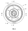
- Fig. 8 is a top plan view of a piston that is another embodiment of the invention.
- Fig. 9 is a view taken along line 9-9 of Fig. 8 .
- Fig. 10 is a view taken along line 10-10 of Fig. 8 .
- Fig. 11 is a view taken along line 11-11 of Fig. 8 .
- Fig. 12 is a view taken along line 12-12 of Fig. 9 .
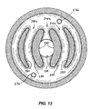
- Fig. 1 is a view taken along line 13-13 of Fig. 11 .
- Fig. 1 illustrates a section view of an internal combustion engine 10 in which one embodiment of the present invention is employed.
- the engine 10 is a two-stroke, diesel aircraft engine, however, it should be understood that the present invention can also be used in other engines.
- the engine 10 includes an engine block 12 at least partially defining a crankcase 14 and a cylinder 15.
- a crankshaft (not shown) is rotatably supported within the crankcase 14 and includes a crank pin 16.
- One end 18 of a connecting rod 20 is rotatably coupled to the crank pin 16, and the other end 22 of the connecting rod 20 is coupled to a piston 24 located within the cylinder 15 for reciprocation within the cylinder 15.
- a cylinder head 26 is threadingly engaged to the engine block 12 to cover the cylinder 15.
- a fuel injector 28 extends through the cylinder head 26 and injects fuel into a combustion chamber 30 defined by the cylinder head 26, the cylinder 15, and the piston 24.
- the piston 24 includes a skirt 32 and a crown 34 connected to the top of the skirt 32.
- the crown 34 is generally disc-shaped and includes a top surface configured to correctly direct the motion of the charge from the fuel injector 28 within the combustion chamber 30.
- the bottom surface of the crown 34 includes a centrally-extending threaded boss 40 and a downwardly-extending flange 42 about the periphery of the crown 34.
- the boss 40 includes a bore 44, and the bottom surface includes an annular groove 46 between the flange 42 and the boss 40.
- the skirt 32 includes a generally disc-shaped top portion 48 and a cylindrical wall 50 extending downwardly from the periphery of the top portion 48.
- the upper surface of the top portion 48 includes a recessed edge 54 along the periphery, a centrally located threaded bore 56, and an annular groove 58 located between the central bore 56 and the recessed edge 54.
- a first annular wall 60 separates the annular groove 58 and the central bore 56, and a second annular wall 62 separates the annular groove 58 and the recessed edge 54.
- the upper surface includes a first recess 64 within the annular groove 58 on one side of a central axis 66 and a second recess 64 Within the annular groove 58 on the opposite side of the central axis 66.
- the bottom surface of the top portion 48 includes a raised portion 70 that includes an arcuate bearing surface 72.
- the bearing surface 72 extends along a longitudinal axis 74 between a first aperture 76 on one side of the wall 50 to another aperture 74 on the other side of the wall 50 ( Fig. 2 ).
- the longitudinal axis 74 defines a longitudinal plane 78, and the interior side 80 of the wall 50 and the lower surface of the skirt 32 define a skirt cavity 82.
- the top portion 48 includes an inlet hole 84 located on one side of the central axis 66 and an exit hole 85 located on the other side of the central axis 66 opposite to the inlet hole 84.
- the inlet hole 84 and the exit hole 85 extend between the annular groove 58 and the lower surface of the skirt 32 to fluidly communicate between the annular groove 58 and the skirt cavity 82.
- the inlet hole 84 and the exit hole 85 taper in the direction toward the annular groove 58.
- the top portion 48 also includes a first passageway 86 on one side of the central axis 66 and a second passageway 86 located on the other side of the central axis 66 opposite to the first passageway 86.
- the passageways 86 fluidly communicate between the annular groove 58 and the central bore 56. More specifically, each passageway 86 includes a diameter of 187 inches and angles downward from a first end located adjacent to the bottom of the annular groove 58 to a second end located adjacent to the bottom of the central bore 56. As shown in Fig. 7 , each passageway 86 defines an angle a, which preferably equals approximately 50 degrees.
- the top portion includes outer lubricating holes 88 located near the annular wall 62.
- the outer lubricating holes 88 include a first pair on one side of the central axis 66 and a second pair on the other side of the central axis 66 opposite to the first pair.
- Each pair includes a first outer lubricating hole 88 offset a distance from the longitudinal plane 78 and a second outer lubricating hole 88 offset a similar distance on the opposite side of the longitudinal plane 78.
- Each outer lubricating hole 88 extends between the bottom surface of the annular groove 58 and the bearing surface 72 to fluidly communicate between the annular groove 58 and the skirt cavity 82.
- the top portion 48 includes two intermediate lubricating holes 90 located within the recesses 64 along the longitudinal plane 78.
- the intermediate lubricating holes 90 extend between the bottom surface of the recess 64 to the bearing surface 72 to fluidly communicate between the annular groove 58 and the skirt cavity 82.
- the top portion 48 includes a central lubricating hole 92 located within the central bore 56 along the central axis 66 and the longitudinal plane 78.
- the central lubricating hole 92 extends between the bottom surface of the central bore 56 and the bearing surface 72 to fluidly communicate between the central bore 56 and the skirt cavity 82.
- each of the lubricating holes 88, 90, 92 includes a diameter of approximately .125 inches.
- the crown 34 is connected to the skirt 32 by threading the boss 40 into the bore 56 such that the flange 42 is forced against the recessed edge 54 to form a seal.
- the annular grooves 46, 58 align to define an annular gallery 94, and the bore 44 combines with the central bore 56 to define a central cavity 96.
- the illustrated annular grooves 46, 58 are only one example of how the annular gallery 94 could be formed, and other annular galleries formed with annular grooves of varying depths are within the scope of the present invention. Additionally, the annular gallery 94 can be formed entirely by the annular groove of the skirt 32 or the crown 34.
- the central cavity 96 can be formed entirely within the skirt 32, crown 34, or any combination of recesses on the skirt 32 and the crown 34. It should also be noted that the positions of the hollow boss 40 and the bore 56 could be reversed such that the hollow boss 40 is located on the skirt 32 and the bore 56 is located on the crown 34. Other methods of connecting the crown 34 and the skirt 32 to form the annular gallery 94 and the central cavity 96 are known to those skilled in the art and are within the scope of the present invention.
- a wristpin 98 is positioned through both apertures 76 and is rotatably supported by the wall 50.
- the wristpin 98 is a cylindrical tube having an exterior surface and an interior surface separated by a thickness. The upper portion of the exterior surface defines a bearing surface 100 that is in direct contact with the bearing surface 72.
- the lower portion of the wristpin 98 includes two holes 102.
- the end 22 of the connecting rod 20 includes an arcuate portion 104 that contacts the lower portion of the wristpin 98.
- the arcuate portion 104 has an arcuate extent that extends about 180 degrees.
- a plurality of fasteners 106 extend through holes 108 in the arcuate portion 104 and into the holes 102 of the wristpin 98 to secure the wristpin 98 to the arcuate portion 104.
- the connecting rod 20 and the wristpin 98 could also be connected by extending the fasteners 106 into an annular wristpin insert (not shown) positioned within the wristpin 98 adjacent to the interior surface.
- the bearing surface 100 of the wristpin 98 directly contacts the bearing surface 72 of the skirt 32. This allows the upward forces of the wristpin 98 to be evenly distributed along the entire bearing surface 72 of the raised portion and the downward forces of the piston 24 to be evenly distributed along the entire bearing surface 100 of the wristpin 98.
- the increased area of the bearing surfaces 72, 100 minimizes uneven wear on the bearing surfaces 72, 100 during operation of the engine 10.
- the piston 24 reciprocates in response to explosions within the combustion chamber 30 thereby rotating the crankshaft through the connecting rod 20.
- a collimated jet of lubricant is propelled from an injection nozzle (not shown) into the skirt cavity 82 where the lubricant is directed into the inlet hole 84.
- the lubricant passes through the inlet hole 84 to collect into the annular gallery 94.
- the lubricant absorbs the heat of the piston 24, thereby removing heat from the piston 24 to cool the piston 24.
- the lubricant flows out of the lubrication holes 88, 90, 92, flows into the passageways 86, or flows out of the exit hole 85.
- the lubrication that flows from the outer lubrication holes 88 flows directly to the bearing surface 72 offset from the longitudinal plane 78 to lubricate the bearing surfaces 72, 100 of the wristpin 98 and the skirt 32.
- the lubricant that flows from the intermediate lubrication holes 90 flows directly to the bearing surface 72 along the longitudinal plane 78 to lubricate the bearing surfaces 72, 100 of the wristpin 98 and the skirt 32.
- the recesses 64 within the annular groove 58 accumulate lubricant in order to concentrate flow of lubricant through the intermediate lubrication holes 90 and along the centerline of the bearing surfaces 72, 100, i.e., along the longitudinal plane 78.
- the portion of the lubricant that flows through the passageways 86 collects in the central cavity 96. From the central cavity 96, the lubricant flows through the central lubrication hole 92 directly to the center of the bearing surface 72 along the central axis 66 to lubricate the bearing surfaces 72, 100 of the wristpin 98 and the skirt 32.
- Lubricant flows directly from the annular gallery 94 of the piston 24 to the bearing surfaces 72, 100 of the wristpin 98 and the skirt 32 to thoroughly lubricate the bearing surfaces 72, 100.
- This is advantageous over known lubrication systems because known systems expel cooling lubricant from a piston to a wristpin that is spaced a distance from the lower surface of the piston. The distance between the lower surface of the piston and the wristpin makes it difficult to control the flow of the lubricant toward the wristpin bearing surface.
- the lubrication system of the present invention precisely directs the lubricant exiting the piston annular gallery 94 between the bearing surfaces 72, 100 of the wristpin 98 and the skirt 32.
- Figs. 8 through 13 illustrate a piston 200 that is an alternative embodiment of the invention. Except as described below, the piston 200 is substantially identical to the piston 24.
- the piston 200 includes a generally disc-shaped top portion 204 and a generally cylindrically-shaped wall portion or skirt 208 extending downwardly from the top portion 204.
- the top and wall portions define a skirt cavity 212.
- the upper surface of the top portion 204 includes a centrally located threaded bore 214, and an annular groove 215 surrounding the central bore 214.
- the piston also includes a crown (not shown) substantially identical to the crown 34 of the piston 24.
- the crown has a bottom surface with a centrally-extending boss threaded into the bore 214.
- the bottom surface of the top portion 204 includes a downwardly extending projection 216 having (see Fig. 10 ) opposite right and left sides 217, 218 facing the skirt cavity 212.
- the projection 216 has a downwardly facing bearing surface 220 for the wristpin (not shown).
- the bearing surface 220 extends in the direction of a longitudinal axis 224 between (see Fig. 9 ) an aperture 226 on one side of the wall portion 208 and an aperture 228 on the other side of the wall portion 208.
- the bearing surface 220 defines a portion of a cylinder centered on the axis 224.
- the wristpin (not shown) pivots about the axis 224.
- the piston 200 has a vertical central axis 230 intersecting the axis 224, and the axes 224 and 230 define a plane 232.
- the plane 232 appears the same as the axis 230 in Fig. 10 and is the plane of the paper in Fig. 9 .
- annular groove 215 When the crown is secured to the top portion 204, the annular groove 215 forms an annular chamber 234 which communicate with the skirt cavity 212 via diametrically opposed passages 236 shown in Figs. 8 , 12 and 13 .
- An oil jet or P tube (not shown) shoots oil into the chamber 234 through one of the passages 236 to cool the crown and the top portion of the piston. The oil in the chamber 234 returns to the skirt cavity through the other passage 236.
- Each lubricant passage 240 includes (see Fig. 10 ) an upwardly facing surface 242 that includes a central trough 244.
- the trough 244 of each passage 240 has a lowermost central portion, extends in the direction of the axis 224, and has a low point extending along a line 245 ( Fig. 9 ) that is parallel to the axis 224 and is located in the plane 232.
- each lubricant passage 240 preferably includes (see Fig. 10 ) a first or left portion 248 that ramps upwardly from the left side of the projection 216 toward the trough 244, and a second or left portion 252 that ramps upwardly from the right side of the projection 216 toward the trough 244.
- the upward angle of each of the surfaces 248, 252 increases adjacent the trough 244, and the surface 242 forms parallel ridges 254, 256 on opposite sides of the trough 244.
- the surface portion 248 has a lower end, and a generally horizontal portion 258 extends outward from the lower end of the surface 248.
- the surface portion 252 has a lower end, and a generally horizontal portion 262 extends outward from the lower end of the surface 252.
- the central passage 240a extends between opposed, radially inwardly facing concave walls 280, and the outer passages 240b and c each extend between a respective radially inwardly facing concave wall 284 and a respective radially outwardly facing convex wall 288.
- each trough 244 communicates with the bearing surface 220 via a respective lubricant opening 250 so that lubricant in each passage 240 is supplied to the bearing surface 220 and to the wristpin.
- the piston 200 includes three lubricant openings 250a, b and c, all of which extend vertically and are located in the plane 232.
- the openings 250a, b and c communicate with the lubricant passages 240a, b and c, respectively.
- the central opening 250a is located on the central axis 230.
- the outer openings 250b and 250c are located on opposite sides of the central opening 250a.
- the bearing surface 220 has therein a relatively shallow groove or recess 254 extending along a line 255 that is parallel to the axis 224 and that is located in the plane 232.
- the lubricant openings 250 all communicate with the groove 254.
- the groove 254 is preferably arcuate in cross-section, as shown in Fig. 10 , and defines a portion of a cylinder. Communication of the openings 250 with the groove 254 improves the distribution of lubricant over the bearing surface 220.
- the piston 200 splashes oil or lubricant into the lubricant passages 240a, b and c. While some of the oil passes completely through the passages 240a, b and c, some comes to rest in the troughs 244 and then flows through one of the openings 250a, b and c to the bearing surface 220 to lubricate the bearing surface 220 and the wristpin.
- the shape of the surfaces 242 has been found to provide the correct amount of lubricant to the bearing surface 220.
- the oil jet or P tube (not shown) shoots oil into the chamber 234 through one of the passages 236 to cool the crown and the top portion of the piston. The oil in the chamber 234 returns to the skirt cavity through the other passage 236.
- each feature disclosed is one example only of a generic series of equivalent or similar features.
- the invention is not restricted to the details of the foregoing embodiment(s).
- the invention extends to any novel one, or any novel combination, of the features disclosed in this specification (including any accompanying claims, abstract and drawings), or to any novel one, or any novel combination, of the steps of any method or process so disclosed.
Landscapes
- Engineering & Computer Science (AREA)
- General Engineering & Computer Science (AREA)
- Chemical & Material Sciences (AREA)
- Combustion & Propulsion (AREA)
- Mechanical Engineering (AREA)
- Physics & Mathematics (AREA)
- Fluid Mechanics (AREA)
- Pistons, Piston Rings, And Cylinders (AREA)
- Lubrication Of Internal Combustion Engines (AREA)
Abstract
Description
- The invention relates to pistons for internal combustion engines, and more particularly to lubricant cooled pistons for internal combustion engines.
- Internal combustion engines generally include a piston that is mounted for reciprocation within a cylinder. The piston is coupled to a crankshaft by a connecting rod such that the reciprocation of the piston rotates the crankshaft. One end of the connecting rod is rotatably connected to a crankpin of the crankshaft and the other end of the connecting rod is connected to a wristpin of the piston. The wristpin can be rotatably connected to the piston and rigidly connected to the connecting rod such that the connecting rod and wristpin rotate relative to the piston as the piston reciprocates within the cylinder. Alternatively, the wristpin can be rigidly connected to the piston and rotatably connected to the connecting rod so that the connecting rod rotates relative to the wristpin and the piston as the piston reciprocates within the cylinder.
- A number of different methods are used to lubricate the wristpin bearing surface. Typically, a hole drilled in the connecting rod transports lubricant supplied from the crankpin to the wristpin. When the connecting rod is rotatably connected to the wristpin, the hole supplies lubricant directly to the bearing surface between the connecting rod and the wristpin. When the connecting rod is rigidly connected to the wristpin, the hole directs lubricant to a passageway through the wristpin to supply the lubricant directly to the bearing surface between the piston and the wristpin.
- It is also known to introduce lubricant into internal passageways within the piston to cool the piston during operation of the engine. Typically, a collimated jet of oil from an injection nozzle is directed into the cooling passageways to remove heat from the piston. In some configurations, the lubricant exits the cooling passageways from the underside of the piston and falls toward the wristpin to assist in lubricating the wristpin bearing surfaces. For example, the top of the connecting rod can include a hole that catches the exiting lubricant and that directs the lubricant to the bearing surface between the connecting rod and the wristpin. Historically, the wristpin has been spaced a distance from the lower surface of the piston and therefore the configurations disclosed in the prior art are incapable of directly lubricating the wristpin bearing surfaces with the lubricant exiting the cooling passages.
- The invention provides a piston for an internal combustion engine, the engine having a connecting rod coupled to a wristpin, the wristpin being connected to the piston for pivotal movement about an axis, the piston comprising: a top portion and a generally cylindrically-shaped wall portion extending from the top portion, the top and wall portions defining a skirt cavity, the top portion having thereon a downwardly extending projection with a downwardly facing bearing surface for the wristpin, the bearing surface extending in the direction of the axis and defining a portion of a cylinder centered on the axis, and the projection having opposite sides facing the skirt cavity; at least one lubricant passage extending through the projection from one of the opposite sides and over the bearing surface to the other of the opposite sides; and a lubricant opening communicating between the lubricant passage and the bearing surface to supply lubricant to the bearing surface and to the wristpin.
- The invention also provides a piston for an internal combustion engine, the engine having a connecting rod coupled to a wristpin, the wristpin being connected to the piston for pivotal movement about an axis, the piston comprising: a top portion and a generally cylindrically-shaped wall portion extending from the top portion, the top and wall portions defining a skirt cavity; a downwardly facing bearing surface for the wristpin, the bearing surface extending in the direction of the axis and defining a portion of a cylinder centered on the axis; a lubricant cavity above the bearing surface, the lubricant cavity having therein a trough with a low point extending along a line parallel to the axis, the line and the axis defining a vertical plane; and a lubricant opening communicating between the low point of the trough and the bearing surface to supply lubricant to the bearing surface and to the wristpin.
- The invention also provides a piston for an internal combustion engine, the engine having a connecting rod coupled to a wristpin, the wristpin being connected to the piston for pivotal movement about an axis, the piston comprising: a top portion and a generally cylindrically-shaped wall portion extending from the top portion, the top and wall portions defining a skirt cavity, the top portion having thereon a downwardly extending projection having opposite sides facing the skirt cavity, and the projection having a downwardly facing bearing surface for the wristpin, the bearing surface extending in the direction of the axis and defining a portion of a cylinder centered on the axis, the bearing surface having therein a groove extending along a line, the line and the axis defining a vertical plane; at least three lubricant passages each extending through the projection from one of the opposite sides and over the bearing surface to the other of the opposite sides, each passage including a middle, an upwardly facing surface with a first portion that ramps upwardly from the one of the sides toward the middle of the passage, a second portion that ramps upwardly from the other of the sides toward the middle of the passage, a trough located between the first and second portions, the trough having a lowermost central portion extending along a line parallel to the axis and in the vertical plane, and generally parallel ridges on opposite sides of the trough; and at least three lubricant openings, each lubricant opening communicating between the lowermost portion of a respective trough and the groove to supply lubricant to the bearing surface and to the wristpin, the lubricant openings extending in the vertical plane.
- The invention also provides a piston for an internal combustion engine, the engine having a connecting rod coupled to a wristpin, the wristpin being connected to the piston for pivotal movement about an axis, the piston comprising: a top portion and a generally cylindrically-shaped wall portion extending from the top portion, the top and wall portions defining a skirt cavity; a downwardly facing bearing surface for the wristpin, the bearing surface extending in the direction of the axis and defining a portion of a cylinder centered on the axis, and the bearing surface having therein a recess; a lubricant cavity above the bearing surface; and a lubricant opening communicating between the lubricant cavity and the recess to supply lubricant to the bearing surface and to the wristpin.
- Other features and advantages of the invention will become apparent to those skilled in the art upon review of the following detailed description, claims, and drawings.
-
Fig. 1 is a partial cross-section view illustrating an engine having a piston assembly embodying the present invention. -
Fig. 2 is a cross-section view taken along line 2-2 ofFig. 1 . -
Fig. 3 is a cross-section view taken along line 3-3 ofFig. 2 . -
Fig. 4 is an exploded view illustrating the piston shown inFig. 1 . -
Fig. 5 is a top view of a skirt of the piston shown inFig. 1 . -
Fig. 6 is a cross-section view taken along line 6-6 ofFig. 5 . -
Fig. 7 is a cross-section view taken along line 7-7 ofFig. 6 . -
Fig. 8 is a top plan view of a piston that is another embodiment of the invention. -
Fig. 9 is a view taken along line 9-9 ofFig. 8 . -
Fig. 10 is a view taken along line 10-10 ofFig. 8 . -
Fig. 11 is a view taken along line 11-11 ofFig. 8 . -
Fig. 12 is a view taken along line 12-12 ofFig. 9 . -
Fig. 1 is a view taken along line 13-13 ofFig. 11 . - Before one embodiment of the invention is explained in detail, it is to be understood that the invention is not limited in its application to the details of construction and the arrangements of the components set forth in the following description or illustrated in the drawings. The invention is capable of other embodiments and of being practiced or being carried out in various ways. Also, it is understood that the phraseology and terminology used herein is for the purpose of description and should not be regarded as limiting. The use of "including" and "comprising" and variations thereof herein is meant to encompass the items listed thereafter and equivalents thereof as well as additional items. The use of"consisting of" and variations thereof herein is meant to encompass only the items listed thereafter. The use of letters to identify elements of a method or process is simply for identification and is not meant to indicate that the elements should be performed in a particular order.
-
Fig. 1 illustrates a section view of aninternal combustion engine 10 in which one embodiment of the present invention is employed. Theengine 10 is a two-stroke, diesel aircraft engine, however, it should be understood that the present invention can also be used in other engines. - The
engine 10 includes anengine block 12 at least partially defining acrankcase 14 and acylinder 15. A crankshaft (not shown) is rotatably supported within thecrankcase 14 and includes acrank pin 16. Oneend 18 of a connectingrod 20 is rotatably coupled to thecrank pin 16, and theother end 22 of the connectingrod 20 is coupled to apiston 24 located within thecylinder 15 for reciprocation within thecylinder 15. Acylinder head 26 is threadingly engaged to theengine block 12 to cover thecylinder 15. Afuel injector 28 extends through thecylinder head 26 and injects fuel into acombustion chamber 30 defined by thecylinder head 26, thecylinder 15, and thepiston 24. - As best illustrated in
Fig. 4 , thepiston 24 includes askirt 32 and acrown 34 connected to the top of theskirt 32. Thecrown 34 is generally disc-shaped and includes a top surface configured to correctly direct the motion of the charge from thefuel injector 28 within thecombustion chamber 30. With further reference toFig. 2 , the bottom surface of thecrown 34 includes a centrally-extending threadedboss 40 and a downwardly-extendingflange 42 about the periphery of thecrown 34. Theboss 40 includes abore 44, and the bottom surface includes anannular groove 46 between theflange 42 and theboss 40. - Referring back to
Fig. 4 , theskirt 32 includes a generally disc-shapedtop portion 48 and acylindrical wall 50 extending downwardly from the periphery of thetop portion 48. The upper surface of thetop portion 48 includes arecessed edge 54 along the periphery, a centrally located threadedbore 56, and anannular groove 58 located between thecentral bore 56 and therecessed edge 54. A firstannular wall 60 separates theannular groove 58 and thecentral bore 56, and a secondannular wall 62 separates theannular groove 58 and therecessed edge 54. The upper surface includes afirst recess 64 within theannular groove 58 on one side of acentral axis 66 and asecond recess 64 Within theannular groove 58 on the opposite side of thecentral axis 66. As shown inFig. 3 , the bottom surface of thetop portion 48 includes a raisedportion 70 that includes an arcuate bearingsurface 72. Thebearing surface 72 extends along alongitudinal axis 74 between afirst aperture 76 on one side of thewall 50 toanother aperture 74 on the other side of the wall 50 (Fig. 2 ). As shown inFig. 3 , thelongitudinal axis 74 defines alongitudinal plane 78, and theinterior side 80 of thewall 50 and the lower surface of theskirt 32 define askirt cavity 82. - Referring to
Figs. 5 and 6 , thetop portion 48 includes aninlet hole 84 located on one side of thecentral axis 66 and anexit hole 85 located on the other side of thecentral axis 66 opposite to theinlet hole 84. Theinlet hole 84 and theexit hole 85 extend between theannular groove 58 and the lower surface of theskirt 32 to fluidly communicate between theannular groove 58 and theskirt cavity 82. Theinlet hole 84 and theexit hole 85 taper in the direction toward theannular groove 58. - Referring to
Figs. 5 and 7 , thetop portion 48 also includes afirst passageway 86 on one side of thecentral axis 66 and asecond passageway 86 located on the other side of thecentral axis 66 opposite to thefirst passageway 86. Thepassageways 86 fluidly communicate between theannular groove 58 and thecentral bore 56. More specifically, eachpassageway 86 includes a diameter of 187 inches and angles downward from a first end located adjacent to the bottom of theannular groove 58 to a second end located adjacent to the bottom of thecentral bore 56. As shown inFig. 7 , eachpassageway 86 defines an angle a, which preferably equals approximately 50 degrees. - As shown in
Figs. 2 and5 , the top portion includes outer lubricating holes 88 located near theannular wall 62. The outer lubricating holes 88 include a first pair on one side of thecentral axis 66 and a second pair on the other side of thecentral axis 66 opposite to the first pair. Each pair includes a firstouter lubricating hole 88 offset a distance from thelongitudinal plane 78 and a second outer lubricatinghole 88 offset a similar distance on the opposite side of thelongitudinal plane 78. Eachouter lubricating hole 88 extends between the bottom surface of theannular groove 58 and the bearingsurface 72 to fluidly communicate between theannular groove 58 and theskirt cavity 82. - As shown in
Figs. 2 and5 , thetop portion 48 includes two intermediate lubricating holes 90 located within therecesses 64 along thelongitudinal plane 78. The intermediate lubricating holes 90 extend between the bottom surface of therecess 64 to the bearingsurface 72 to fluidly communicate between theannular groove 58 and theskirt cavity 82. - With reference to
Figs. 2, 3 and5 , thetop portion 48 includes acentral lubricating hole 92 located within thecentral bore 56 along thecentral axis 66 and thelongitudinal plane 78. Thecentral lubricating hole 92 extends between the bottom surface of thecentral bore 56 and the bearingsurface 72 to fluidly communicate between thecentral bore 56 and theskirt cavity 82. Preferably, each of the lubricating holes 88, 90, 92 includes a diameter of approximately .125 inches. - As best shown in
Figs. 2 and 3 , thecrown 34 is connected to theskirt 32 by threading theboss 40 into thebore 56 such that theflange 42 is forced against the recessededge 54 to form a seal. When thecrown 34 andskirt 32 are connected, theannular grooves annular gallery 94, and thebore 44 combines with thecentral bore 56 to define a central cavity 96. The illustratedannular grooves annular gallery 94 could be formed, and other annular galleries formed with annular grooves of varying depths are within the scope of the present invention. Additionally, theannular gallery 94 can be formed entirely by the annular groove of theskirt 32 or thecrown 34. Similarly, the central cavity 96 can be formed entirely within theskirt 32,crown 34, or any combination of recesses on theskirt 32 and thecrown 34. It should also be noted that the positions of thehollow boss 40 and thebore 56 could be reversed such that thehollow boss 40 is located on theskirt 32 and thebore 56 is located on thecrown 34. Other methods of connecting thecrown 34 and theskirt 32 to form theannular gallery 94 and the central cavity 96 are known to those skilled in the art and are within the scope of the present invention. - With additional reference to
Fig. 4 , awristpin 98 is positioned through bothapertures 76 and is rotatably supported by thewall 50. Thewristpin 98 is a cylindrical tube having an exterior surface and an interior surface separated by a thickness. The upper portion of the exterior surface defines abearing surface 100 that is in direct contact with the bearingsurface 72. The lower portion of thewristpin 98 includes twoholes 102. - The
end 22 of the connectingrod 20 includes anarcuate portion 104 that contacts the lower portion of thewristpin 98. Thearcuate portion 104 has an arcuate extent that extends about 180 degrees. A plurality offasteners 106 extend throughholes 108 in thearcuate portion 104 and into theholes 102 of thewristpin 98 to secure thewristpin 98 to thearcuate portion 104. The connectingrod 20 and thewristpin 98 could also be connected by extending thefasteners 106 into an annular wristpin insert (not shown) positioned within thewristpin 98 adjacent to the interior surface. - As best illustrated in
Fig. 3 , because theend 22 of the connectingrod 20 does not encircle thewristpin 98, the bearingsurface 100 of thewristpin 98 directly contacts the bearingsurface 72 of theskirt 32. This allows the upward forces of thewristpin 98 to be evenly distributed along theentire bearing surface 72 of the raised portion and the downward forces of thepiston 24 to be evenly distributed along theentire bearing surface 100 of thewristpin 98. The increased area of the bearing surfaces 72, 100 minimizes uneven wear on the bearing surfaces 72, 100 during operation of theengine 10. - During operation of the
engine 10, thepiston 24 reciprocates in response to explosions within thecombustion chamber 30 thereby rotating the crankshaft through the connectingrod 20. As thepiston 24 moves toward the crankshaft, a collimated jet of lubricant is propelled from an injection nozzle (not shown) into theskirt cavity 82 where the lubricant is directed into theinlet hole 84. The lubricant passes through theinlet hole 84 to collect into theannular gallery 94. As the lubricant flows in theannular gallery 94, the lubricant absorbs the heat of thepiston 24, thereby removing heat from thepiston 24 to cool thepiston 24.
From theannular gallery 94, the lubricant flows out of the lubrication holes 88, 90, 92, flows into thepassageways 86, or flows out of theexit hole 85. The lubrication that flows from the outer lubrication holes 88 flows directly to the bearingsurface 72 offset from thelongitudinal plane 78 to lubricate the bearing surfaces 72, 100 of thewristpin 98 and theskirt 32. The lubricant that flows from the intermediate lubrication holes 90 flows directly to the bearingsurface 72 along thelongitudinal plane 78 to lubricate the bearing surfaces 72, 100 of thewristpin 98 and theskirt 32. Therecesses 64 within theannular groove 58 accumulate lubricant in order to concentrate flow of lubricant through the intermediate lubrication holes 90 and along the centerline of the bearing surfaces 72, 100, i.e., along thelongitudinal plane 78. - The portion of the lubricant that flows through the
passageways 86 collects in the central cavity 96. From the central cavity 96, the lubricant flows through thecentral lubrication hole 92 directly to the center of the bearingsurface 72 along thecentral axis 66 to lubricate the bearing surfaces 72, 100 of thewristpin 98 and theskirt 32. - Lubricant flows directly from the
annular gallery 94 of thepiston 24 to the bearing surfaces 72, 100 of thewristpin 98 and theskirt 32 to thoroughly lubricate the bearing surfaces 72, 100. This is advantageous over known lubrication systems because known systems expel cooling lubricant from a piston to a wristpin that is spaced a distance from the lower surface of the piston. The distance between the lower surface of the piston and the wristpin makes it difficult to control the flow of the lubricant toward the wristpin bearing surface. In contrast, the lubrication system of the present invention precisely directs the lubricant exiting the pistonannular gallery 94 between the bearing surfaces 72, 100 of thewristpin 98 and theskirt 32. -
Figs. 8 through 13 illustrate apiston 200 that is an alternative embodiment of the invention. Except as described below, thepiston 200 is substantially identical to thepiston 24. - As best illustrated in
Figs. 9 and10 , thepiston 200 includes a generally disc-shapedtop portion 204 and a generally cylindrically-shaped wall portion orskirt 208 extending downwardly from thetop portion 204. The top and wall portions define askirt cavity 212. The upper surface of thetop portion 204 includes a centrally located threadedbore 214, and anannular groove 215 surrounding thecentral bore 214. The piston also includes a crown (not shown) substantially identical to thecrown 34 of thepiston 24. The crown has a bottom surface with a centrally-extending boss threaded into thebore 214. The bottom surface of thetop portion 204 includes a downwardly extendingprojection 216 having (seeFig. 10 ) opposite right and leftsides skirt cavity 212. Theprojection 216 has a downwardly facingbearing surface 220 for the wristpin (not shown). The bearingsurface 220 extends in the direction of alongitudinal axis 224 between (seeFig. 9 ) anaperture 226 on one side of thewall portion 208 and anaperture 228 on the other side of thewall portion 208. The bearingsurface 220 defines a portion of a cylinder centered on theaxis 224. The wristpin (not shown) pivots about theaxis 224. Thepiston 200 has a verticalcentral axis 230 intersecting theaxis 224, and theaxes plane 232. Theplane 232 appears the same as theaxis 230 inFig. 10 and is the plane of the paper inFig. 9 . - When the crown is secured to the
top portion 204, theannular groove 215 forms an annular chamber 234 which communicate with theskirt cavity 212 via diametrically opposedpassages 236 shown inFigs. 8 ,12 and13 . An oil jet or P tube (not shown) shoots oil into the chamber 234 through one of thepassages 236 to cool the crown and the top portion of the piston. The oil in the chamber 234 returns to the skirt cavity through theother passage 236. - Three
lubricant passages 240a, b and c extend through theprojection 216 from one side to the other and over the bearingsurface 220. Thepassage 240a is centrally located, and the passages 240b and c are on opposite sides of thepassage 240a. Each lubricant passage 240 includes (seeFig. 10 ) an upwardly facingsurface 242 that includes acentral trough 244. Thetrough 244 of each passage 240 has a lowermost central portion, extends in the direction of theaxis 224, and has a low point extending along a line 245 (Fig. 9 ) that is parallel to theaxis 224 and is located in theplane 232. - The upwardly facing
surface 242 of each lubricant passage 240 preferably includes (seeFig. 10 ) a first or leftportion 248 that ramps upwardly from the left side of theprojection 216 toward thetrough 244, and a second or leftportion 252 that ramps upwardly from the right side of theprojection 216 toward thetrough 244. The upward angle of each of thesurfaces trough 244, and thesurface 242 formsparallel ridges 254, 256 on opposite sides of thetrough 244. Thesurface portion 248 has a lower end, and a generallyhorizontal portion 258 extends outward from the lower end of thesurface 248. Thesurface portion 252 has a lower end, and a generallyhorizontal portion 262 extends outward from the lower end of thesurface 252. As best shown inFig. 13 , thecentral passage 240a extends between opposed, radially inwardly facingconcave walls 280, and the outer passages 240b and c each extend between a respective radially inwardly facingconcave wall 284 and a respective radially outwardly facingconvex wall 288. - As best shown in
Figs. 9 and10 , the low point of eachtrough 244 communicates with the bearingsurface 220 via arespective lubricant opening 250 so that lubricant in each passage 240 is supplied to thebearing surface 220 and to the wristpin. Thus, thepiston 200 includes threelubricant openings 250a, b and c, all of which extend vertically and are located in theplane 232. Theopenings 250a, b and c communicate with thelubricant passages 240a, b and c, respectively. Thecentral opening 250a is located on thecentral axis 230. Theouter openings 250b and 250c are located on opposite sides of thecentral opening 250a. - As best shown in
Figs. 9 and12 , the bearingsurface 220 has therein a relatively shallow groove orrecess 254 extending along aline 255 that is parallel to theaxis 224 and that is located in theplane 232. Thelubricant openings 250 all communicate with thegroove 254. Thegroove 254 is preferably arcuate in cross-section, as shown inFig. 10 , and defines a portion of a cylinder. Communication of theopenings 250 with thegroove 254 improves the distribution of lubricant over the bearingsurface 220. - During operation of the engine, the
piston 200 splashes oil or lubricant into thelubricant passages 240a, b and c. While some of the oil passes completely through thepassages 240a, b and c, some comes to rest in thetroughs 244 and then flows through one of theopenings 250a, b and c to thebearing surface 220 to lubricate thebearing surface 220 and the wristpin. The shape of thesurfaces 242 has been found to provide the correct amount of lubricant to thebearing surface 220. At the same time, the oil jet or P tube (not shown) shoots oil into the chamber 234 through one of thepassages 236 to cool the crown and the top portion of the piston. The oil in the chamber 234 returns to the skirt cavity through theother passage 236. - The foregoing description of the present invention has been presented for purposes of illustration and description. Furthermore, the description is not intended to limit the invention to the form disclosed herein. Consequently, variations and modifications commensurate with the above teachings, and the skill or knowledge of the relevant art, are within the scope of the present invention. The embodiments described herein are further intended to explain best modes known for practicing the invention and to enable others skilled in the art to utilize the invention in such, or other, embodiments and with various modifications required by the particular applications or uses of the present invention. It is intended that the appended claims be construed to include alternative embodiments to the extent permitted by the prior art. Also, terms such as "left" or "right" or "vertical" in the above description and in the claims are used only to indicate relative orientation and are not intended to be limiting.
Attention is directed to all papers and documents which are filed concurrently with or previous to this specification in connection with this application and which are open to public inspection with this specification, and the contents of all such papers and documents are incorporated herein by reference.
All of the features disclosed in this specification (including any accompanying claims, abstract and drawings), and/or all of the steps of any method or process so disclosed, may be combined in any combination, except combinations where at least some of such features and/or steps are mutually exclusive.
Each feature disclosed in this specification (including any accompanying claims, abstract and drawings) may be replaced by alternative features serving the same, equivalent or similar purpose, unless expressly stated otherwise. Thus, unless expressly stated otherwise, each feature disclosed is one example only of a generic series of equivalent or similar features.
The invention is not restricted to the details of the foregoing embodiment(s). The invention extends to any novel one, or any novel combination, of the features disclosed in this specification (including any accompanying claims, abstract and drawings), or to any novel one, or any novel combination, of the steps of any method or process so disclosed.
Claims (24)
- A piston for an internal combustion engine, the engine having a connecting rod coupled to a wristpin, the wristpin being connected to the piston for pivotal movement about an axis, the piston comprising:a top portion and a generally cylindrically-shaped wall portion extending from the top portion, the top and wall portions defining a skirt cavity, the top portion having thereon a downwardly extending projection with a downwardly facing bearing surface for the wristpin, the bearing surface extending in the direction of the axis and defining a portion of a cylinder centered on the axis, and the projection having opposite sides facing the skirt cavity;at least one lubricant passage extending through the projection from one of the opposite sides and over the bearing surface to the other of the opposite sides; anda lubricant opening communicating between the lubricant passage and the bearing surface to supply lubricant to the bearing surface and to the wristpin.
- A piston for an internal combustion engine, the engine having a connecting rod coupled to a wristpin, the wristpin being connected to the piston for pivotal movement about an axis, the piston comprising:a top portion and a generally cylindrically-shaped wall portion extending from the top portion, the top and wall portions defining a skirt cavity;a downwardly facing bearing surface for the wristpin, the bearing surface extending in the direction of the axis and defining a portion of a cylinder centered on the axis;a lubricant cavity above the bearing surface, the lubricant cavity having therein a trough with a low point extending along a line parallel to the axis, the line and the axis defining a vertical plane; anda lubricant opening communicating between the low point of the trough and the bearing surface to supply lubricant to the bearing surface and to the wristpin.
- A piston for an internal combustion engine, the engine having a connecting rod coupled to a wristpin, the wristpin being connected to the piston for pivotal movement about an axis, the piston comprising:a top portion and a generally cylindrically-shaped wall portion extending from the top portion, the top and wall portions defining a skirt cavity;a downwardly facing bearing surface for the wristpin, the bearing surface extending in the direction of the axis and defining a portion of a cylinder centered on the axis, and the bearing surface having therein a recess;a lubricant cavity above the bearing surface; anda lubricant opening communicating between the lubricant cavity and the recess to supply lubricant to the bearing surface and to the wristpin.
- The piston of claim 1, wherein the lubricant passage includes an upwardly facing surface that includes a trough, and wherein the lubricant opening communicates with the trough.
- The piston of claim 4, wherein the trough has a lowermost central portion, and wherein the lubricant opening communicates with the central portion.
- The piston of claim 5, wherein the trough extends in the direction of the axis.
- The piston of claim 6, wherein the trough has a low point extending along a line parallel to the axis, the line and the axis defining a vertical plane.
- The piston of claim 1 or 2, wherein the bearing surface has therein a recess with which the lubricant opening communicates.
- The piston of claim 3 or 8, wherein the recess is a groove extending in the direction of the axis.
- The piston of claim 9, wherein the groove extends along a line parallel to the axis, the line and the axis defining a vertical plane.
- The piston of claim 10, wherein the groove is arcuate in cross-section.
- The piston of claim 11, wherein the groove defines a portion of a cylinder.
- The piston of claim 4, wherein the upwardly facing surface also includes a first portion that ramps upwardly from the one of the sides toward the trough, and a second portion that ramps upwardly from the other of the sides toward the trough.
- The piston of claim 2, wherein the lubricant cavity communicates with the skirt cavity and includes an upwardly facing surface with a first portion that ramps upwardly toward the middle of the cavity, and with a second portion that ramps upwardly toward the middle of the cavity, and wherein the trough is located between the first and second portions.
- The piston of claim 13 or 14, wherein the upward angle of each of the first and second portions increases adjacent the trough.
- The piston of claim 15, wherein the upwardly facing surface forms generally parallel ridges on opposite sides of the trough.
- The piston of claim 16, wherein the first and second portions of the upwardly facing surface have respective lower ends, and wherein the upwardly facing surface also includes a first generally horizontal portion extending outward from the lower end of the first portion, and a second generally horizontal portion extending outward from the lower end of the second portion.
- The piston of claim 1, wherein the piston comprises at least three lubricant passages extending through the projection from one of the opposite sides and over the bearing surface to the other of the opposite sides, and at least three lubricant openings, with each lubricant opening communicating between a respective lubricant passage and the bearing surface to supply lubricant to the bearing surface and to the wristpin.
- The piston of claim 18, wherein the lubricant openings extend vertically and define a plane including the axis.
- The piston of claim 1, 2, or 3, wherein the top portion has therein a threaded central bore for attachment of a crown.
- The piston of claim 2, wherein the trough has a central portion that includes the low point, and wherein the lubricant opening communicates with the central portion.
- The piston of claim 2, wherein the piston comprises at least three lubricant cavities with respective troughs, each trough having a low point extending along the line parallel to the axis, and the piston also comprising at least three lubricant openings, with each lubricant opening communicating between the low point of a respective trough and the bearing surface to supply lubricant to the bearing surface and to the wristpin.
- The piston of claim 3, wherein the piston comprises at least three lubricant cavities, and the piston also comprising at least three lubricant openings, with each lubricant opening communicating between a respective lubricant cavity and the recess to supply lubricant to the bearing surface and to the wristpin.
- The piston of claim 22 or 23, wherein the lubricant openings extend vertically and in the vertical plane.
Applications Claiming Priority (1)
| Application Number | Priority Date | Filing Date | Title |
|---|---|---|---|
| US11/688,285 US7836815B2 (en) | 2002-05-15 | 2007-03-20 | Lubricant-cooled and wristpin lubricating piston |
Publications (1)
| Publication Number | Publication Date |
|---|---|
| EP1972773A2 true EP1972773A2 (en) | 2008-09-24 |
Family
ID=39620255
Family Applications (1)
| Application Number | Title | Priority Date | Filing Date |
|---|---|---|---|
| EP08152990A Withdrawn EP1972773A2 (en) | 2007-03-20 | 2008-03-19 | A lubricant-cooled and wristpin lubricating piston |
Country Status (5)
| Country | Link |
|---|---|
| US (1) | US7836815B2 (en) |
| EP (1) | EP1972773A2 (en) |
| AU (1) | AU2008201212A1 (en) |
| BR (1) | BRPI0800650A (en) |
| CA (1) | CA2625901A1 (en) |
Families Citing this family (5)
| Publication number | Priority date | Publication date | Assignee | Title |
|---|---|---|---|---|
| US8474366B2 (en) * | 2007-08-13 | 2013-07-02 | Federal-Mogul Corporation | Piston with a skirt having oil flow slots and method of construction thereof |
| US8839749B2 (en) * | 2011-06-07 | 2014-09-23 | Mahle Koenig Kommanditgesellschaft Gmbh & Co. Kg | Piston having a hollow cooling space defined in a mantle wall |
| GB2509355A (en) * | 2012-10-23 | 2014-07-02 | Ecomotors Internat Inc | A piston system |
| US9841049B2 (en) * | 2015-06-05 | 2017-12-12 | Achates Power, Inc. | Load transfer point offset of rocking journal wristpins in uniflow-scavenged, opposed-piston engines with phased crankshafts |
| US20190301606A1 (en) * | 2018-03-30 | 2019-10-03 | Federal-Mogul Llc | Lubrication feature for pin of two stroke piston assembly |
Family Cites Families (13)
| Publication number | Priority date | Publication date | Assignee | Title |
|---|---|---|---|---|
| US1404621A (en) * | 1921-02-12 | 1922-01-24 | Walter H Livingood | Piston for internal-combustion engines |
| US1890914A (en) * | 1929-09-12 | 1932-12-13 | Ingersoll Rand Co | Engine |
| US1800077A (en) * | 1930-05-06 | 1931-04-07 | Henry M Jennings | Internal-combustion-engine piston |
| US2159989A (en) * | 1937-04-19 | 1939-05-30 | Gen Motors Corp | Welded two-piece light alloy piston |
| US2843433A (en) * | 1954-10-21 | 1958-07-15 | Burnand John | Pistons for internal combustion engines |
| US3613521A (en) * | 1968-11-07 | 1971-10-19 | Komatsu Mfg Co Ltd | Piston for internal combustion engine |
| FR2238372A5 (en) * | 1973-07-19 | 1975-02-14 | Dampers | |
| US4013057A (en) * | 1975-05-14 | 1977-03-22 | Dana Corporation | Piston assembly |
| US4180027A (en) * | 1977-07-20 | 1979-12-25 | Mack Trucks, Inc. | Two-piece oil-cooled piston |
| US4635596A (en) * | 1985-08-12 | 1987-01-13 | Kawasaki Jukogyo Kabushiki Kaisha | Assembly of piston and connecting rod in internal-combustion engine |
| ES2266011T3 (en) * | 1999-10-08 | 2007-03-01 | Federal-Mogul Corporation | PISTON WITH DOUBLE GALLERY. |
| AU2002213255A1 (en) * | 2000-10-18 | 2002-04-29 | Federal Mogul Corporation | Multi-axially forged piston |
| US6491013B1 (en) * | 2001-09-19 | 2002-12-10 | Federal-Mogul World Wide, Inc. | Closed gallery piston having reinforced oil hole |
-
2007
- 2007-03-20 US US11/688,285 patent/US7836815B2/en not_active Expired - Fee Related
-
2008
- 2008-03-14 AU AU2008201212A patent/AU2008201212A1/en not_active Abandoned
- 2008-03-17 CA CA002625901A patent/CA2625901A1/en not_active Abandoned
- 2008-03-19 EP EP08152990A patent/EP1972773A2/en not_active Withdrawn
- 2008-03-20 BR BRPI0800650-4A patent/BRPI0800650A/en not_active IP Right Cessation
Also Published As
| Publication number | Publication date |
|---|---|
| BRPI0800650A (en) | 2008-11-04 |
| US20070227350A1 (en) | 2007-10-04 |
| AU2008201212A1 (en) | 2008-10-09 |
| US7836815B2 (en) | 2010-11-23 |
| CA2625901A1 (en) | 2008-09-20 |
Similar Documents
| Publication | Publication Date | Title |
|---|---|---|
| US6701875B2 (en) | Internal combustion engine with piston cooling system and piston therefor | |
| CN101548080B (en) | Internal combustion engine | |
| US4945864A (en) | Two cycle engine piston lubrication | |
| KR20040058233A (en) | Closed gallery monobloc piston having oil drainage groove | |
| EP1972773A2 (en) | A lubricant-cooled and wristpin lubricating piston | |
| US6494170B2 (en) | Two-piece piston assembly with skirt having pin bore oil ducts | |
| JP6546189B2 (en) | Piston cooling arrangements utilizing lubricating oil from bearing oil reservoirs in opposed piston engines | |
| US12320312B2 (en) | Piston assembly with opposing injection regions for an opposed-piston engine | |
| US6786643B2 (en) | Cam bracket | |
| US8726859B2 (en) | Two-stroke cycle combustion engine of air scavenging type | |
| US20050211089A1 (en) | Lubricant-cooled and wristpin lubricating piston | |
| US5860395A (en) | Piston cooling by oil flow from a pocket reservoir and passageway formed in the piston | |
| US20050045121A1 (en) | Multicylinder four-cycle combustion engine | |
| WO2010017442A1 (en) | Integrally cast block and upper crankcase | |
| HK1122087A (en) | A lubricant-cooled and wristpin lubricating piston | |
| US20080295683A1 (en) | Focal oiling for a piston assembly | |
| JP2005331056A (en) | Engine bearing lubrication structure | |
| EP1321635A1 (en) | Oil drainage passage for an internal combustion engine | |
| JPH04211763A (en) | Piston for four-stroke internal combustion engine | |
| US6742491B1 (en) | Engine lubrication system | |
| JPH0960725A (en) | Internal combustion engine pistons | |
| RU2105160C1 (en) | Internal combustion engine crank gear lubrication and cooling system | |
| JP2004270489A (en) | piston | |
| JPS585455A (en) | Piston | |
| RU95112774A (en) | CRUISE LUBRICATION AND COOLING COOLING MECHANISM OF INTERNAL COMBUSTION ENGINE |
Legal Events
| Date | Code | Title | Description |
|---|---|---|---|
| PUAI | Public reference made under article 153(3) epc to a published international application that has entered the european phase |
Free format text: ORIGINAL CODE: 0009012 |
|
| AK | Designated contracting states |
Kind code of ref document: A2 Designated state(s): AT BE BG CH CY CZ DE DK EE ES FI FR GB GR HR HU IE IS IT LI LT LU LV MC MT NL NO PL PT RO SE SI SK TR |
|
| AX | Request for extension of the european patent |
Extension state: AL BA MK RS |
|
| REG | Reference to a national code |
Ref country code: HK Ref legal event code: DE Ref document number: 1122087 Country of ref document: HK |
|
| STAA | Information on the status of an ep patent application or granted ep patent |
Free format text: STATUS: THE APPLICATION IS DEEMED TO BE WITHDRAWN |
|
| 18D | Application deemed to be withdrawn |
Effective date: 20131001 |
|
| REG | Reference to a national code |
Ref country code: HK Ref legal event code: WD Ref document number: 1122087 Country of ref document: HK |