EP1972755A2 - A casing arrangement - Google Patents
A casing arrangement Download PDFInfo
- Publication number
- EP1972755A2 EP1972755A2 EP08250547A EP08250547A EP1972755A2 EP 1972755 A2 EP1972755 A2 EP 1972755A2 EP 08250547 A EP08250547 A EP 08250547A EP 08250547 A EP08250547 A EP 08250547A EP 1972755 A2 EP1972755 A2 EP 1972755A2
- Authority
- EP
- European Patent Office
- Prior art keywords
- ring
- casing
- arrangement
- retainer
- panel
- Prior art date
- Legal status (The legal status is an assumption and is not a legal conclusion. Google has not performed a legal analysis and makes no representation as to the accuracy of the status listed.)
- Withdrawn
Links
- 230000000717 retained effect Effects 0.000 claims description 4
- 238000000748 compression moulding Methods 0.000 claims description 3
- 230000002787 reinforcement Effects 0.000 claims description 3
- 230000007246 mechanism Effects 0.000 claims description 2
- 238000005553 drilling Methods 0.000 abstract 1
- 238000004026 adhesive bonding Methods 0.000 description 4
- 230000009471 action Effects 0.000 description 3
- 239000000853 adhesive Substances 0.000 description 3
- 230000001070 adhesive effect Effects 0.000 description 3
- 239000002131 composite material Substances 0.000 description 3
- 230000014759 maintenance of location Effects 0.000 description 3
- 238000000034 method Methods 0.000 description 3
- 230000008569 process Effects 0.000 description 3
- 229910000831 Steel Inorganic materials 0.000 description 2
- 230000005534 acoustic noise Effects 0.000 description 2
- 238000004873 anchoring Methods 0.000 description 2
- 230000000694 effects Effects 0.000 description 2
- 239000002657 fibrous material Substances 0.000 description 2
- 239000011521 glass Substances 0.000 description 2
- 238000001746 injection moulding Methods 0.000 description 2
- 239000000463 material Substances 0.000 description 2
- 239000002184 metal Substances 0.000 description 2
- 238000000465 moulding Methods 0.000 description 2
- 230000009467 reduction Effects 0.000 description 2
- 230000003014 reinforcing effect Effects 0.000 description 2
- 239000010959 steel Substances 0.000 description 2
- 230000003313 weakening effect Effects 0.000 description 2
- OKTJSMMVPCPJKN-UHFFFAOYSA-N Carbon Chemical compound [C] OKTJSMMVPCPJKN-UHFFFAOYSA-N 0.000 description 1
- 230000004075 alteration Effects 0.000 description 1
- 229910052799 carbon Inorganic materials 0.000 description 1
- 238000010276 construction Methods 0.000 description 1
- 230000001419 dependent effect Effects 0.000 description 1
- 238000009499 grossing Methods 0.000 description 1
- 238000009434 installation Methods 0.000 description 1
- 230000003993 interaction Effects 0.000 description 1
- 238000012986 modification Methods 0.000 description 1
- 230000004048 modification Effects 0.000 description 1
- 230000008439 repair process Effects 0.000 description 1
- 238000011144 upstream manufacturing Methods 0.000 description 1
Images


Classifications
-
- F—MECHANICAL ENGINEERING; LIGHTING; HEATING; WEAPONS; BLASTING
- F02—COMBUSTION ENGINES; HOT-GAS OR COMBUSTION-PRODUCT ENGINE PLANTS
- F02K—JET-PROPULSION PLANTS
- F02K1/00—Plants characterised by the form or arrangement of the jet pipe or nozzle; Jet pipes or nozzles peculiar thereto
- F02K1/78—Other construction of jet pipes
- F02K1/82—Jet pipe walls, e.g. liners
- F02K1/827—Sound absorbing structures or liners
-
- F—MECHANICAL ENGINEERING; LIGHTING; HEATING; WEAPONS; BLASTING
- F01—MACHINES OR ENGINES IN GENERAL; ENGINE PLANTS IN GENERAL; STEAM ENGINES
- F01D—NON-POSITIVE DISPLACEMENT MACHINES OR ENGINES, e.g. STEAM TURBINES
- F01D25/00—Component parts, details, or accessories, not provided for in, or of interest apart from, other groups
- F01D25/24—Casings; Casing parts, e.g. diaphragms, casing fastenings
- F01D25/243—Flange connections; Bolting arrangements
-
- F—MECHANICAL ENGINEERING; LIGHTING; HEATING; WEAPONS; BLASTING
- F02—COMBUSTION ENGINES; HOT-GAS OR COMBUSTION-PRODUCT ENGINE PLANTS
- F02C—GAS-TURBINE PLANTS; AIR INTAKES FOR JET-PROPULSION PLANTS; CONTROLLING FUEL SUPPLY IN AIR-BREATHING JET-PROPULSION PLANTS
- F02C7/00—Features, components parts, details or accessories, not provided for in, or of interest apart form groups F02C1/00 - F02C6/00; Air intakes for jet-propulsion plants
- F02C7/24—Heat or noise insulation
-
- F—MECHANICAL ENGINEERING; LIGHTING; HEATING; WEAPONS; BLASTING
- F05—INDEXING SCHEMES RELATING TO ENGINES OR PUMPS IN VARIOUS SUBCLASSES OF CLASSES F01-F04
- F05B—INDEXING SCHEME RELATING TO WIND, SPRING, WEIGHT, INERTIA OR LIKE MOTORS, TO MACHINES OR ENGINES FOR LIQUIDS COVERED BY SUBCLASSES F03B, F03D AND F03G
- F05B2260/00—Function
- F05B2260/30—Retaining components in desired mutual position
- F05B2260/301—Retaining bolts or nuts
-
- Y—GENERAL TAGGING OF NEW TECHNOLOGICAL DEVELOPMENTS; GENERAL TAGGING OF CROSS-SECTIONAL TECHNOLOGIES SPANNING OVER SEVERAL SECTIONS OF THE IPC; TECHNICAL SUBJECTS COVERED BY FORMER USPC CROSS-REFERENCE ART COLLECTIONS [XRACs] AND DIGESTS
- Y02—TECHNOLOGIES OR APPLICATIONS FOR MITIGATION OR ADAPTATION AGAINST CLIMATE CHANGE
- Y02T—CLIMATE CHANGE MITIGATION TECHNOLOGIES RELATED TO TRANSPORTATION
- Y02T50/00—Aeronautics or air transport
- Y02T50/60—Efficient propulsion technologies, e.g. for aircraft
Definitions
- the present invention relates to casing arrangements and more particularly to retaining liner casing panels in a gas turbine engine.
- Turbofan gas turbine engines for powering aircraft conventionally comprise an engine core, which drives a fan.
- the fan comprises a number of radially extending fan blades mounted on a fan rotor, enclosed by a generally cylindrical or frustoconical fan casing.
- the engine core comprises one or more turbines, each one of which comprises a number of radially extending turbine blades, enclosed by a generally cylindrical or frustoconical casing.
- containment rings for turbofan gas turbine engine casings is well known. It is known to provide generally cylindrical or frustoconical, relatively thick, metallic containment rings. It is also known to provide generally cylindrical or frustoconical, locally thickened, isogrid metal containment rings. Furthermore, it is known to provide strong fibrous material wound around relatively thin metallic casings to extend from containment casings. In the event that a blade becomes detached to prevent parts through the casing those parts are contained by the fibrous material in the panel or panels.
- the fan case liner is attached within the fan casing by mechanical fasteners passing through the liner and secured into or through the fan casing, or by adhesive.
- Adhesive bonding of the fan case liner to the fan casing must be performed under controlled conditions. If a liner has to be replaced in service it may be difficult to control the bonding conditions and this can result in unsatisfactory attachment of the replacement liner to the casing. It can be difficult to remove a damaged liner without also damaging the fan casing.
- the design of fan casings has to include an allowance for possible weakening caused by such damage. This increases the cost and weight of the fan casing.
- a casing arrangement comprising a ring placed within a casing in use and the ring associated with a retainer for a panel, the retainer configured to appropriately present the panel relative to a casing about which the ring is placed without a direct mechanical fixing between the panel and the casing, and location reformed by the assembly of the ring, the retainer and the panel.
- the ring is sized to provide a snug fit within the casing. Possibly, the ring has an interference fit within the casing. Alternatively, the ring may be able to fit within the casing or outside of the casing.
- the ring is segmented.
- the retainer incorporates a rail to receive an end of the panel.
- the retainer is a compression moulding.
- the retainer is integrally formed with the panel.
- the retainer is formed from steel or a glass composite material.
- the panel has an integral rib reinforcement structure.
- the retainer is secured to the ring by a captive bolt.
- the arrangement comprises a plurality of panels associated with the ring in use.
- the arrangement incorporates a dam feature to retain location of the ring within the casing in use.
- dam features are provided at both ends of the arrangement.
- the ring is additionally adhesive bonded.
- the arrangement includes an adjustment clip.
- the adjustment clip includes a tab for location relative to the ring.
- the retainer is a U section ring and the ring clamps against the U section ring to cause distortion in use to retain the U section ring against the casing.
- a gas turbine engine including a casing arrangement as described above.
- the ring may be secured to the casing at an appropriate location where stressing may not be a problem and as the ring will only require mechanical fixings at that position.
- aspects of the present invention provide a loose ring which, in view of the configuration of the casing and/or provision of dam elements as described later, ensures that the panels are appropriately located within a casing as required.
- present panels In such circumstances in gas turbine engine fan casings which have areas where it is not possible for stress reasons to drill holes, it is possible with an arrangement in accordance with aspects of the present invention, to present panels. It will be appreciated these panels may be for acoustic noise reduction effects or to act as flow path smoothing surfaces or for debris containment reasons.
- Fig. 1 provides a schematic cross section of a casing arrangement 1 in accordance with aspects of the present invention.
- the arrangement 1 comprises a casing 2 which is generally an annulus about a centre line 3.
- a ring 4 is located and placed at one end which has a loose or snug or an interference fit within the casing 2.
- the ring 4 is of a segmented nature to allow assembly within the casing 2 with appropriate cross segment retainers to define the ring upon installation.
- the ring 4 is also associated with retainer elements 5 in order to present a panel or panels 6 appropriately adjacent to the casing 2.
- the panels 6 as indicated previously may be for acoustic noise or for other reasons.
- the retainers 5 are robustly secured to the ring 4 but overall the arrangement has no mechanical connection between the casing 2 and the ring 4, the retainers 5 and the panels 6.
- the retainers 5 generally incorporate a rail or other facility to engage and present the panel 6 in use.
- the retainers 5 may subtend the whole arc of the ring 5 or parts of segments as required provided sufficiently robust presentation of the panels 6 is achieved.
- casings 2 are of a conical tapering configuration in the direction of thrust (schematically shown as A) and therefore the panel 6 along with ring 4 and retainers 5 will be squeezed into the taper of that conical and therefore location maintained when assembled.
- A direction of thrust
- dam element in the casing or through use of wedges or other elements, it will be possible to prevent such movement in any event in the opposite direction to tapering.
- the retainer ring 4 is generally produced in segments which are attached together using over spanning joint straps. Generally, these joint straps will be fastened to outer (convex) surfaces of the ring 4 and possibly counter sunk.
- the ring will generally be formed from an appropriate material such as steel or carbon or a glass composite which has sufficient mechanical strength to allow anchoring of the retainers 5.
- the retainers 5 will be secured to the ring through a captive bolt arrangement as depicted in Fig. 2 .
- the ring 4 is again located within the casing 2 with a bolt 10 extending from an inner surface 11 outwardly to retain association between the retainer 5 and the ring 4.
- the bolt 10 has a nut 14 to capture the association between the ring 4 and the retainer 5.
- a head 13 of the bolt 10 is generally shaped and countersunk to provide a consistent flat surface with the inner surface 11 of the arrangement 1.
- the ring 4 will generally incorporate cut out segments within which the nuts 6 can be located and secured using an appropriate tool. In such circumstances the association between the ring 4 and the retainer 5 is robust. With a robust association between the ring 4 and the retainer 5, it will be understood that the panels 6, which themselves are relatively rigid, are appropriately presentation of the panel 6 relative to the casing 2.
- the retainer 5 will normally incorporate appropriate rail segments to interlock the panel 6 with the retainer 5. It will also be understood that the retainer 5 may be integrally formed with the panels 6 to ensure appropriate presentation.
- the retainer 5 essentially presents the panel 6 within the casing 2. Thus, the relationship and interaction at an interface 12 is important with regard to achieving an appropriate presentation in use.
- the retainer 5 will be substantially rigid and the panel 6 will generally be a conventional honeycomb structure with composite or metal skins on both sides incorporating the retainer 5. Alternatively, the panel 6 could be an injection moulding.
- the panel 6 may incorporate an integral reinforcement rib or other structure to again ensure that this panel 6 is stiff and remains in the desired shape for association adjacent to the casing 2. This shape will normally be curved so that the panel is flat to the casing 2.
- the ring 4 in terms of its segments, and the panel 6 will have circumferential lengths so that when assembled respective panels 6 will bridge joint strap positions between ring 5 segments. Such configuration will further strengthen the assembly in use.
- the ring 4 is so dimensioned that the retainer 5 held by the bolt 10 can be screwed in the direction of arrowhead B into the ring such that the retainer 5 is closely associated with the ring 4 which in turn will configure the panels 6 so that they are pushed against the casing 2.
- the combined ring 4 and retainer 5 give a high degree of rigidity and impact resistance to the arrangement 1.
- casings can take a number of forms as indicated above including a conical or tapering casing which narrows from a generally forward broader opening end to a narrower exit end.
- a casing arrangement in accordance with aspects of the present invention with a loose retainer ring will be arranged such that the panels of the arrangement will remain in place in view of the nature of flow being towards the narrower construction.
- a dam arrangement can be provided upstream of the ring to dampen and prevent lateral axis travel within the casing.
- a parallel casing that is to say a generally consistent cylindrical casing dam elements can be provided at both ends to prevent movement of the ring.
- an alternative is to provide one retaining ring at one end of the arrangement which is secured to the casing through bolts.
- the engine and therefore casing configuration can be determined such that apertures through the casing to accommodate the retaining bolts will be at positions where stressing and reduction in the mechanical strength of the casing is less important.
- the embodiment of the present invention depicted in Fig. 2 may be modified and varied by specifying that the diameter 21 of the retaining ring 4 is greater than a location face 22 of the rail 5. Thus, there is a gap 23 between the ring 4 and face 22. In such circumstances if the present arrangement is assembled outside of the casing 2 then the ring can be slightly larger than a location face 22. However, by tightening the bolts 10 this may cause a slight local distortion of the ring 4 enabling the panel 6 to be pressed into contact with casing bore 2.
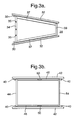
- Fig. 3 schematically illustrates a conical tapering configuration in Fig. 3a and a parallel cylindrical configuration in Fig. 3b with regard to casing arrangements in accordance with aspects of the present invention.
- Fig. 3a illustrates a conical or tapered casing configuration in accordance with aspects of the present invention.
- a casing 32 is associated with a ring 34 of a segmented nature with joint straps 35 provided between inter sections 36 of the ring 34.
- panels 37 are arranged adjacent to the casing 32 and as indicated extend across segmented sections 36 for improved structural strength.
- the ring 34 incorporates retainers (not shown) which appropriately present the panels 37 relative to the casing 32.
- the casing 32 narrows and tapers towards an end 38 and in accordance with aspects of the present invention a further loose or closely fitting ring 39 may be provided to ensure that both ends of the panel 37 are appropriately robustly retained and maintained relative to the casing 32.
- a dam 30 is provided in order to prevent lateral movement of the panels 37 along with rings 34, 35.
- the dam 30 is engaged by a respective ring or parts of the retainer in order to maintain position within the casing 32. It will be appreciated that in view of the tapering nature of the casing 32 that typically only a dam 30 at the front end of the casing 32 is required to prevent axial movement as the arrangement will be squeezed into the tapering end and therefore cannot move significantly. However, where required a dam can be provided at both ends.
- Fig. 3b illustrates a parallel cylindrical configuration of a casing arrangement in accordance with aspects of the present invention.
- the casing 42 incorporates rings 44, 54 which are associated with retainers (not shown) for presentation of panels 46.
- the general configuration depicted in Fig. 3b is similar to that described previously in that the panels 46 through the retainers and anchoring to the loosely fitting rings 44 are located within the casing 42 as required.
- dams 40, 50 are provided at each end of the arrangement to prevent such lateral movement for engagement with the respective rings 44, 54.
- aspects of the present invention are provided in order to avoid structurally weakening apertures in the casing 42 being necessary in order to support and present casings as required. Nevertheless, it will also be appreciated there are parts of the casing within which such apertures may be acceptable and therefore by appropriate choice of positioning of rings and retainers in accordance with aspects of the present invention it will be understood that rings at one end of an arrangement may be secured through bolts into the casing and therefore movement anchored by those bolts rather than or in addition to use of dams as anchors in accordance with aspects of the present invention.
- Figs. 4 to 6 provide schematic illustrations of a second embodiment of a casing arrangement in accordance with aspects of the present invention.
- panels 56 are located about a casing 52 and retained in position by a U section ring 55 which in turn is secured by bolts 50 and a clamp ring 54.
- the ring 55 as indicated, is generally U shaped in section in order to allow the panels 56 to be bolted relative to it.
- the ring 55 has clearance holes 51 through which the bolts 50 extend.
- the bolts secure the panels by passing through a section of the panel 56 and engaging with the ring 55 through the clamp ring 54.
- the bolts 50 are retained by a retaining nut 64.
- the clamp ring 54 is also segmented and, as illustrated, sits within the U section of the ring 55.
- the ring 55 and the clamp ring 54 as indicated are formed from segments and typically there are an equal number of segments but arranged on assembly with staggered joints.
- the clamp ring 54 is generally slightly over sized with a gap 63 between the clamp ring 54 and the U section ring 55.
- Fig. 5 illustrates a first alternative with regard to creating an over size condition in the clamp ring 54 depicted in Fig. 4 .
- clamp ring segments 54a, 54b are locally deformed whereby when the bolt 50 is fitted and tightened flattening of the segments 54a, 54b increases the circumference of the clamp ring 54.
- such distortion will cause local deformation of the U shaped ring 55 and so engagement with the casing 52.
- Fig. 6 illustrates a second alternative approach to creating an over size condition with regard to a clamp ring 54 as depicted in Fig. 4 .
- the clamp ring 54 is presented upon a rubber strip 65.
- the bolt 50 is tightened there will be a resultant distortion in the over size clamp ring 54 being pulled inward and forcing the U shape section 55 locally against the casing 52 ( Fig. 4 ).
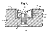
- Fig. 7 illustrates a third alternative approach to creating an over size condition with regard to a clamp ring similar to that depicted in Fig. 4 .
- a ring 74 is arranged to be presented within a recess 70 formed in a panel 76.
- the ring 74 is secured through a bolt 60 and a retaining or captive nut 94.
- faces 81 of the ring 74 may overlap shoulder portions of the recess 70 such that the interface between the portions 81 and the shoulder portions may be secured together through an adhesive bond if required.
- the ring 74 includes clearance holes for the bolt 60.
- adjustment clips 82 are provided (only one is shown) which are engaged by a respective captive nut 94.
- the clips 82 fit inside mounting positions of the ring 74 such that by tightening the bolts against the nuts 94 the panel 76 is secured. It will be noted that generally there is an expansion effect on the mounting ring caused by the action of the bolt end through the captive nut 94 against the clip 82.
- tabs 83 will be provided. These tabs 83 will locate the clips 82 relative to the mounting ring and therefore facilitate association during expansion in accordance with aspects of the present invention.
- the captive nut 94 will be located within the clip 82 such that when the bolt 60 is presented the bolt will screw through the nut 94 and cause engagement against expander portions 84 of the clip 82. Such action will cause expansion of the clip 82 and therefore action against the ring 74 within the recesses 70. Thus, as indicated, the panel 76 will be located and secured.
- Panels in accordance with aspects of the present invention will generally be structurally rigid in order to retain their configuration.
- the retainers and rings in accordance with aspects of the present invention prevent panel movement radially inward and the panels themselves are sufficiently rigid to prevent distortion and bowing causing inward movement.
- the rings appropriately present and configure the panels in use and therefore either through use of simple dam elements inwardly projecting from the casings or where allowed bolts at one point in the casing, a whole arrangement when assembled is provided which achieves panel presentation within a casing arrangement which is more acceptable.
- the materials from which the ring, retainers and panels are made may be chosen dependent upon particular requirements.
- the panels may incorporate themselves reinforcing rib structures formed integrally during a moulding process. This moulding process may be an injection moulding process or compression moulding process as required.
- intermediate reinforcing rings 60 ( Fig. 3b ) which do not incorporate retainers but simply have appropriate means for securing panels to the ring through bolts extending through the ring and the panel as required. In such circumstances the intermediate rings 60 will reduce the unsupported length of the panels 46 whilst providing a robust annular ring to reinforce the panel as required.
- adhesive bonding between the ring and the retainer or with intermediate rings between the ring and the panel directly may be possible.
Landscapes
- Engineering & Computer Science (AREA)
- Chemical & Material Sciences (AREA)
- Combustion & Propulsion (AREA)
- Mechanical Engineering (AREA)
- General Engineering & Computer Science (AREA)
- Connection Of Plates (AREA)
- Patch Boards (AREA)
Abstract
Description
- The present invention relates to casing arrangements and more particularly to retaining liner casing panels in a gas turbine engine.
- Turbofan gas turbine engines for powering aircraft conventionally comprise an engine core, which drives a fan. The fan comprises a number of radially extending fan blades mounted on a fan rotor, enclosed by a generally cylindrical or frustoconical fan casing. The engine core comprises one or more turbines, each one of which comprises a number of radially extending turbine blades, enclosed by a generally cylindrical or frustoconical casing.
- There is a remote possibility with such engines that part or all of a fan blade or a turbine blade could become detached from the remainder of the fan or turbine. In the case of a fan blade becoming detached this may occur as a result of, for example, the turbofan gas turbine engine ingesting a bird or other foreign object.
- The use of containment rings for turbofan gas turbine engine casings is well known. It is known to provide generally cylindrical or frustoconical, relatively thick, metallic containment rings. It is also known to provide generally cylindrical or frustoconical, locally thickened, isogrid metal containment rings. Furthermore, it is known to provide strong fibrous material wound around relatively thin metallic casings to extend from containment casings. In the event that a blade becomes detached to prevent parts through the casing those parts are contained by the fibrous material in the panel or panels.
- There is a requirement to provide a fan case liner within the fan casing. Conventionally, the fan case liner is attached within the fan casing by mechanical fasteners passing through the liner and secured into or through the fan casing, or by adhesive.
- Conventional mechanical attachment of fan case liners uses fasteners extending radially through reinforced regions of the liner panel. These fasteners produce steps and gaps, which interfere with the aerodynamic flow over the liner panel. The presence of the reinforced regions increases the weight and cost of the liner panels. Furthermore the fasteners must be secured into or through the fan casing, which weakens the casing and may interfere with its ability to contain a detached fan blade.
- Adhesive bonding of the fan case liner to the fan casing must be performed under controlled conditions. If a liner has to be replaced in service it may be difficult to control the bonding conditions and this can result in unsatisfactory attachment of the replacement liner to the casing. It can be difficult to remove a damaged liner without also damaging the fan casing. The design of fan casings has to include an allowance for possible weakening caused by such damage. This increases the cost and weight of the fan casing.
- In view of the above it will be appreciated that both conventional mechanical fixings extending through the casing and adhesive bonding are generally unsatisfactory.
- In accordance with aspects of the present invention there is provided a casing arrangement comprising a ring placed within a casing in use and the ring associated with a retainer for a panel, the retainer configured to appropriately present the panel relative to a casing about which the ring is placed without a direct mechanical fixing between the panel and the casing, and location reformed by the assembly of the ring, the retainer and the panel.
- Generally, the ring is sized to provide a snug fit within the casing. Possibly, the ring has an interference fit within the casing. Alternatively, the ring may be able to fit within the casing or outside of the casing.
- Generally, the ring is segmented.
- Typically, the retainer incorporates a rail to receive an end of the panel. Typically, the retainer is a compression moulding. Possibly, the retainer is integrally formed with the panel. Possibly, the retainer is formed from steel or a glass composite material.
- Possibly, the panel has an integral rib reinforcement structure.
- Possibly, the retainer is secured to the ring by a captive bolt.
- Generally, the arrangement comprises a plurality of panels associated with the ring in use.
- Possibly, the arrangement incorporates a dam feature to retain location of the ring within the casing in use. Possibly, dam features are provided at both ends of the arrangement.
- Possibly, the ring is additionally adhesive bonded. Possibly, the arrangement includes an adjustment clip. Possibly, the adjustment clip includes a tab for location relative to the ring.
- Possibly, the retainer is a U section ring and the ring clamps against the U section ring to cause distortion in use to retain the U section ring against the casing.
- Also in accordance with aspects of the present invention there is provided a gas turbine engine including a casing arrangement as described above.
- Embodiments of the present invention will now be described by way of example and with reference to the accompanying drawings in which:-
-
Fig. 1 is a schematic cross section of a first embodiment of a casing arrangement in accordance with one aspect of the present invention; -
Fig. 2 is a schematic illustration of a ring, a retainer and a panel adjacent a casing in accordance with aspects of the present invention; -
Fig. 3 is a schematic illustration of two particular configurations of a casing arrangement in accordance with aspects of the present invention; -
Fig. 4 is a schematic cross section of a second embodiment of a casing arrangement in accordance with aspects of the present invention; -
Fig. 5 is a schematic illustration of a first approach to creating an over size condition for retention in accordance with the embodiment of the invention depicted inFig. 4 ; -
Fig. 6 is a schematic illustration of a second alternative to create an over size condition for retention in accordance with an arrangement as depicted inFig. 4 ; and, -
Fig. 7 is a schematic illustration of a third alternative to create an over size condition for retention in accordance with an arrangement depicted inFig. 4 . - As indicated above, introducing apertures which can provide sites of weakness within a casing should be avoided. The obvious alternative of utilising an adhesive bonding mechanism in itself has problems if repairs are required. Aspects of the present invention utilise location of a generally loose fit or interference fit ring placed within the casing which acts as an anchor upon which a retainer for presenting a panel is configured such that the panel can then be presented adjacent to the casing or as otherwise required. In such circumstances the ring is not secured to the casing and therefore does not introduce areas of weakness whilst the panel itself along with a retainer are also mechanically separate from the casing. However, it will be appreciated that the ring may be secured to the casing at an appropriate location where stressing may not be a problem and as the ring will only require mechanical fixings at that position. However, aspects of the present invention provide a loose ring which, in view of the configuration of the casing and/or provision of dam elements as described later, ensures that the panels are appropriately located within a casing as required. In such circumstances in gas turbine engine fan casings which have areas where it is not possible for stress reasons to drill holes, it is possible with an arrangement in accordance with aspects of the present invention, to present panels. It will be appreciated these panels may be for acoustic noise reduction effects or to act as flow path smoothing surfaces or for debris containment reasons.
-
Fig. 1 provides a schematic cross section of acasing arrangement 1 in accordance with aspects of the present invention. Thearrangement 1 comprises acasing 2 which is generally an annulus about acentre line 3. Within thecasing 2, aring 4 is located and placed at one end which has a loose or snug or an interference fit within thecasing 2. Generally, thering 4 is of a segmented nature to allow assembly within thecasing 2 with appropriate cross segment retainers to define the ring upon installation. Thering 4 is also associated withretainer elements 5 in order to present a panel orpanels 6 appropriately adjacent to thecasing 2. Thepanels 6 as indicated previously may be for acoustic noise or for other reasons. As will be described later, theretainers 5 are robustly secured to thering 4 but overall the arrangement has no mechanical connection between thecasing 2 and thering 4, theretainers 5 and thepanels 6. - The
retainers 5 generally incorporate a rail or other facility to engage and present thepanel 6 in use. Theretainers 5 may subtend the whole arc of thering 5 or parts of segments as required provided sufficiently robust presentation of thepanels 6 is achieved. - It will be appreciated in use the
casing 2 along with thering 4,retainers 5 andpanels 6 are substantially stable whilst rotary parts of an engine are located within acore 7. Generally, the rotating parts rotate about thecentre line 3 in order to generate thrust or provide power in a prime mover assembly. In such circumstances by appropriate location of thering 4 it will be appreciated that an anchor is provided upon which thering 5 can then present thepanel 6 in use. By provision of such an anchor thepanels 6 are located and so will not move laterally within thecasing 2 when assembled. It will be appreciated that somecasings 2 are of a conical tapering configuration in the direction of thrust (schematically shown as A) and therefore thepanel 6 along withring 4 andretainers 5 will be squeezed into the taper of that conical and therefore location maintained when assembled. As will be described later provision of a dam element in the casing or through use of wedges or other elements, it will be possible to prevent such movement in any event in the opposite direction to tapering. - As indicated the
retainer ring 4 is generally produced in segments which are attached together using over spanning joint straps. Generally, these joint straps will be fastened to outer (convex) surfaces of thering 4 and possibly counter sunk. - It will be understood that the ring will generally be formed from an appropriate material such as steel or carbon or a glass composite which has sufficient mechanical strength to allow anchoring of the
retainers 5. - Generally, the
retainers 5 will be secured to the ring through a captive bolt arrangement as depicted inFig. 2 . Thus, as can be seen, thering 4 is again located within thecasing 2 with abolt 10 extending from aninner surface 11 outwardly to retain association between theretainer 5 and thering 4. Thebolt 10 has anut 14 to capture the association between thering 4 and theretainer 5. Ahead 13 of thebolt 10 is generally shaped and countersunk to provide a consistent flat surface with theinner surface 11 of thearrangement 1. Thering 4 will generally incorporate cut out segments within which thenuts 6 can be located and secured using an appropriate tool. In such circumstances the association between thering 4 and theretainer 5 is robust. With a robust association between thering 4 and theretainer 5, it will be understood that thepanels 6, which themselves are relatively rigid, are appropriately presentation of thepanel 6 relative to thecasing 2. - The
retainer 5 will normally incorporate appropriate rail segments to interlock thepanel 6 with theretainer 5. It will also be understood that theretainer 5 may be integrally formed with thepanels 6 to ensure appropriate presentation. Theretainer 5 essentially presents thepanel 6 within thecasing 2. Thus, the relationship and interaction at aninterface 12 is important with regard to achieving an appropriate presentation in use. Theretainer 5 will be substantially rigid and thepanel 6 will generally be a conventional honeycomb structure with composite or metal skins on both sides incorporating theretainer 5. Alternatively, thepanel 6 could be an injection moulding. Thepanel 6 may incorporate an integral reinforcement rib or other structure to again ensure that thispanel 6 is stiff and remains in the desired shape for association adjacent to thecasing 2. This shape will normally be curved so that the panel is flat to thecasing 2. - Further to ensure appropriate assembly generally the
ring 4, in terms of its segments, and thepanel 6 will have circumferential lengths so that when assembledrespective panels 6 will bridge joint strap positions betweenring 5 segments. Such configuration will further strengthen the assembly in use. - In view of the above it will be understood that the
ring 4 is so dimensioned that theretainer 5 held by thebolt 10 can be screwed in the direction of arrowhead B into the ring such that theretainer 5 is closely associated with thering 4 which in turn will configure thepanels 6 so that they are pushed against thecasing 2. When assembled the combinedring 4 andretainer 5 give a high degree of rigidity and impact resistance to thearrangement 1. - It will be understood that casings can take a number of forms as indicated above including a conical or tapering casing which narrows from a generally forward broader opening end to a narrower exit end. In such circumstances a casing arrangement in accordance with aspects of the present invention with a loose retainer ring will be arranged such that the panels of the arrangement will remain in place in view of the nature of flow being towards the narrower construction. However, to prevent vibration or "bounce back" movement following removal of the flow pressure, a dam arrangement can be provided upstream of the ring to dampen and prevent lateral axis travel within the casing. Similarly, with a parallel casing, that is to say a generally consistent cylindrical casing dam elements can be provided at both ends to prevent movement of the ring. It will be appreciated an alternative is to provide one retaining ring at one end of the arrangement which is secured to the casing through bolts. In such circumstances the engine and therefore casing configuration can be determined such that apertures through the casing to accommodate the retaining bolts will be at positions where stressing and reduction in the mechanical strength of the casing is less important.
- The embodiment of the present invention depicted in
Fig. 2 may be modified and varied by specifying that thediameter 21 of the retainingring 4 is greater than alocation face 22 of therail 5. Thus, there is agap 23 between thering 4 andface 22. In such circumstances if the present arrangement is assembled outside of thecasing 2 then the ring can be slightly larger than alocation face 22. However, by tightening thebolts 10 this may cause a slight local distortion of thering 4 enabling thepanel 6 to be pressed into contact withcasing bore 2. -
Fig. 3 schematically illustrates a conical tapering configuration inFig. 3a and a parallel cylindrical configuration inFig. 3b with regard to casing arrangements in accordance with aspects of the present invention. - As indicated above,
Fig. 3a illustrates a conical or tapered casing configuration in accordance with aspects of the present invention. As previously acasing 32 is associated with aring 34 of a segmented nature withjoint straps 35 provided betweeninter sections 36 of thering 34. In use,panels 37 are arranged adjacent to thecasing 32 and as indicated extend acrosssegmented sections 36 for improved structural strength. Thering 34 as indicated incorporates retainers (not shown) which appropriately present thepanels 37 relative to thecasing 32. As can be seen thecasing 32 narrows and tapers towards anend 38 and in accordance with aspects of the present invention a further loose or closelyfitting ring 39 may be provided to ensure that both ends of thepanel 37 are appropriately robustly retained and maintained relative to thecasing 32. Adam 30 is provided in order to prevent lateral movement of thepanels 37 along withrings dam 30 is engaged by a respective ring or parts of the retainer in order to maintain position within thecasing 32. It will be appreciated that in view of the tapering nature of thecasing 32 that typically only adam 30 at the front end of thecasing 32 is required to prevent axial movement as the arrangement will be squeezed into the tapering end and therefore cannot move significantly. However, where required a dam can be provided at both ends. - Although it is advantageous to provide a
downstream ring 39 and its appropriate retainers to secure the end of thepanels 37 to prevent flapping etc. It will also be understood if thepanels 37 are appropriately stiff such that such flapping is substantially eliminated then thering 39 along with retainers may not be required. In such circumstances a dam may be provided to act directly on aring 39 or directly upon thepanels 37 as required and if necessary. -
Fig. 3b illustrates a parallel cylindrical configuration of a casing arrangement in accordance with aspects of the present invention. In such circumstances thecasing 42 incorporatesrings panels 46. In such circumstances the general configuration depicted inFig. 3b is similar to that described previously in that thepanels 46 through the retainers and anchoring to the looselyfitting rings 44 are located within thecasing 42 as required. However, in view of the cylindrical and parallel nature of thecasings 42 it will be appreciated there is a significant possibility of lateral axial slide movement of the arrangement within thecasing 42. In such circumstances in order to preventsuch movement dams respective rings - As indicated above, aspects of the present invention are provided in order to avoid structurally weakening apertures in the
casing 42 being necessary in order to support and present casings as required. Nevertheless, it will also be appreciated there are parts of the casing within which such apertures may be acceptable and therefore by appropriate choice of positioning of rings and retainers in accordance with aspects of the present invention it will be understood that rings at one end of an arrangement may be secured through bolts into the casing and therefore movement anchored by those bolts rather than or in addition to use of dams as anchors in accordance with aspects of the present invention. -
Figs. 4 to 6 provide schematic illustrations of a second embodiment of a casing arrangement in accordance with aspects of the present invention. Thus, as depicted inFig. 4 panels 56 are located about acasing 52 and retained in position by aU section ring 55 which in turn is secured bybolts 50 and aclamp ring 54. Thering 55, as indicated, is generally U shaped in section in order to allow thepanels 56 to be bolted relative to it. Thering 55 hasclearance holes 51 through which thebolts 50 extend. The bolts secure the panels by passing through a section of thepanel 56 and engaging with thering 55 through theclamp ring 54. Thebolts 50 are retained by a retainingnut 64. Theclamp ring 54 is also segmented and, as illustrated, sits within the U section of thering 55. - The
ring 55 and theclamp ring 54 as indicated are formed from segments and typically there are an equal number of segments but arranged on assembly with staggered joints. Theclamp ring 54 is generally slightly over sized with agap 63 between theclamp ring 54 and theU section ring 55. As thebolts 50 are tightened ends of theclamp ring 54 segments touch such that, as will be described later with regard to two possible options illustrated inFigs. 5 and 6 , theU section ring 55 is clamped against theclamp ring 54 and as theclamp ring 54 circumference becomes too large it locally distorts and forces theU section ring 55 into retaining engagement with thecasing 52. It will be appreciated if in an alternative the panels are located outside of thecasing 52 then the parts when assembled will be arranged such that the assembled U shape ring will be slightly larger than the casing due to the U sections being clamped to a clamp ring of an over sized circumference. -
Fig. 5 illustrates a first alternative with regard to creating an over size condition in theclamp ring 54 depicted inFig. 4 . As can be seen, clampring segments bolt 50 is fitted and tightened flattening of thesegments clamp ring 54. Thus, as indicated above, such distortion will cause local deformation of the U shapedring 55 and so engagement with thecasing 52. -
Fig. 6 illustrates a second alternative approach to creating an over size condition with regard to aclamp ring 54 as depicted inFig. 4 . Theclamp ring 54 is presented upon arubber strip 65. In such circumstances when thebolt 50 is tightened there will be a resultant distortion in the oversize clamp ring 54 being pulled inward and forcing theU shape section 55 locally against the casing 52 (Fig. 4 ). -
Fig. 7 illustrates a third alternative approach to creating an over size condition with regard to a clamp ring similar to that depicted inFig. 4 . Thus, a ring 74 is arranged to be presented within arecess 70 formed in apanel 76. The ring 74 is secured through abolt 60 and a retaining orcaptive nut 94. As can be seen, faces 81 of the ring 74 may overlap shoulder portions of therecess 70 such that the interface between theportions 81 and the shoulder portions may be secured together through an adhesive bond if required. - In order to provide expansion to fit, as indicated previously, the ring 74 includes clearance holes for the
bolt 60. Within the ring 74 adjustment clips 82 are provided (only one is shown) which are engaged by a respectivecaptive nut 94. - As indicated, the
clips 82 fit inside mounting positions of the ring 74 such that by tightening the bolts against the nuts 94 thepanel 76 is secured. It will be noted that generally there is an expansion effect on the mounting ring caused by the action of the bolt end through thecaptive nut 94 against theclip 82. - In order to provide location of the
clip 82 upon the ring 74 typicallytabs 83 will be provided. Thesetabs 83 will locate theclips 82 relative to the mounting ring and therefore facilitate association during expansion in accordance with aspects of the present invention. - The
captive nut 94 will be located within theclip 82 such that when thebolt 60 is presented the bolt will screw through thenut 94 and cause engagement againstexpander portions 84 of theclip 82. Such action will cause expansion of theclip 82 and therefore action against the ring 74 within therecesses 70. Thus, as indicated, thepanel 76 will be located and secured. - Panels in accordance with aspects of the present invention will generally be structurally rigid in order to retain their configuration. Thus, the retainers and rings in accordance with aspects of the present invention prevent panel movement radially inward and the panels themselves are sufficiently rigid to prevent distortion and bowing causing inward movement. In such circumstances the rings appropriately present and configure the panels in use and therefore either through use of simple dam elements inwardly projecting from the casings or where allowed bolts at one point in the casing, a whole arrangement when assembled is provided which achieves panel presentation within a casing arrangement which is more acceptable.
- Modifications and alterations to the present invention will be appreciated by those skilled in the art. For example, the materials from which the ring, retainers and panels are made may be chosen dependent upon particular requirements. Furthermore, as indicated the panels may incorporate themselves reinforcing rib structures formed integrally during a moulding process. This moulding process may be an injection moulding process or compression moulding process as required. Furthermore, it may be possible to provide intermediate reinforcing rings 60 (
Fig. 3b ) which do not incorporate retainers but simply have appropriate means for securing panels to the ring through bolts extending through the ring and the panel as required. In such circumstances theintermediate rings 60 will reduce the unsupported length of thepanels 46 whilst providing a robust annular ring to reinforce the panel as required. It will also be understood that in some circumstances instead of bolts, adhesive bonding between the ring and the retainer or with intermediate rings between the ring and the panel directly may be possible.
Claims (20)
- A casing arrangement comprising a ring (4) placed within a casing (2) in use and the ring (4) associated with a retainer (5) for a panel (6), the retainer (5) configured to appropriately present the panel (6) relative to a casing (2) about which the ring (4) is placed without a direct mechanical fixing between the ring (4) and the casing (2) and location retained by the assembly of the ring (4), the retainer (5) and the panel (6).
- An arrangement as claimed in claim 1 wherein the ring (4) is generally sized to provide a loose fit within the casing (2).
- An arrangement as claimed in claim 1 wherein the ring (4) has an interference fit within the casing (2).
- An arrangement as claimed in any preceding claim wherein the ring (4) is segmented.
- An arrangement as claimed in any preceding claim wherein the retainer (5) incorporates a rail to receive an end of the panel (6).
- An arrangement as claimed in any preceding claim wherein the retainer (5) is a compression moulding.
- An arrangement as claimed in any preceding claim wherein the retainer (5) is integrally formed with the panel (6).
- An arrangement as claimed in any preceding claim wherein the panel (6) has an integral rib reinforcement structure.
- An arrangement as claimed in any preceding claim wherein the retainer (5) is secured to the ring (4) by a captive bolt (10).
- An arrangement as claimed in any preceding claim wherein the retainer (5) is secured to the ring (4) by a quarter lock bayonet.
- An arrangement as claimed in any preceding claim wherein the retainer (5) is secured to the ring (4) by a spring latch or other securing mechanism.
- An arrangement as claimed in any preceding claim wherein the arrangement comprises a plurality of panels (6) associated with the ring (4) in use.
- An arrangement as claimed in any preceding claim wherein the arrangement incorporates a dam feature (30) to retain location of the ring (34) within the casing (32) in use.
- An arrangement as claimed in claim 13 wherein dam features (30) are provided at both ends of the arrangement.
- An arrangement as claimed in any preceding claim wherein an aperture in the casing is bound by the panels (6).
- An arrangement as claimed in any preceding claim wherein the retainer is a U section ring (55) and the ring (54) clamps against the U section ring (55) to cause distortion in use to retain the U section ring (55) against the casing (52).
- An arrangement as claimed in any preceding claim wherein the ring (4) is adhesively bonded.
- An arrangement as claimed in any preceding claim wherein the arrangement includes an adjustment clip (82).
- An arrangement as claimed in claim 18 wherein the adjustment clip (82) includes a tab (83) for location relative to the ring (74).
- A gas turbine engine incorporating a casing arrangement as claimed in any preceding claim.
Applications Claiming Priority (1)
| Application Number | Priority Date | Filing Date | Title |
|---|---|---|---|
| GBGB0704879.6A GB0704879D0 (en) | 2007-03-14 | 2007-03-14 | A Casing arrangement |
Publications (2)
| Publication Number | Publication Date |
|---|---|
| EP1972755A2 true EP1972755A2 (en) | 2008-09-24 |
| EP1972755A3 EP1972755A3 (en) | 2013-06-05 |
Family
ID=37988940
Family Applications (1)
| Application Number | Title | Priority Date | Filing Date |
|---|---|---|---|
| EP08250547.0A Withdrawn EP1972755A3 (en) | 2007-03-14 | 2008-02-16 | A casing arrangement |
Country Status (3)
| Country | Link |
|---|---|
| US (1) | US8186934B2 (en) |
| EP (1) | EP1972755A3 (en) |
| GB (1) | GB0704879D0 (en) |
Cited By (1)
| Publication number | Priority date | Publication date | Assignee | Title |
|---|---|---|---|---|
| FR2999650A1 (en) * | 2012-12-17 | 2014-06-20 | Snecma | REMOVABLE ACOUSTIC PANELS FOR TURBOREACTOR HOUSING. |
Families Citing this family (11)
| Publication number | Priority date | Publication date | Assignee | Title |
|---|---|---|---|---|
| GB0916823D0 (en) * | 2009-09-25 | 2009-11-04 | Rolls Royce Plc | Containment casing for an aero engine |
| GB0917149D0 (en) * | 2009-10-01 | 2009-11-11 | Rolls Royce Plc | Impactor containment |
| US8816221B2 (en) | 2012-02-29 | 2014-08-26 | Hamilton Sundstrand Corporation | Low electrical resistance bond |
| US9334756B2 (en) | 2012-09-28 | 2016-05-10 | United Technologies Corporation | Liner and method of assembly |
| US20160245518A1 (en) * | 2013-10-04 | 2016-08-25 | United Technologies Corporation | Combustor panel with multiple attachments |
| US10094242B2 (en) | 2014-02-25 | 2018-10-09 | United Technologies Corporation | Repair or remanufacture of liner panels for a gas turbine engine |
| US10260522B2 (en) | 2016-05-19 | 2019-04-16 | Rolls-Royce Corporation | Liner system |
| US11352953B2 (en) | 2019-04-05 | 2022-06-07 | Rolls-Royce Corporation | Acoustic panel with reinforced lip |
| US11313324B2 (en) | 2019-04-12 | 2022-04-26 | Rolls-Royce Corporation | Systems and methods of acoustic dampening in a gas turbine engine |
| US11680524B1 (en) * | 2021-12-16 | 2023-06-20 | Rolls-Royce Corporation | Turbine engine acoustic panel with outer flange case mounting |
| US12084977B1 (en) | 2023-10-10 | 2024-09-10 | Rolls-Royce North American Technologies Inc. | Gas turbine engine with fan track liner having triply periodic minimal surface reinforcement |
Citations (1)
| Publication number | Priority date | Publication date | Assignee | Title |
|---|---|---|---|---|
| GB2407344A (en) | 2003-10-22 | 2005-04-27 | Rolls Royce Plc | Gas turbine engine casing liner mounting |
Family Cites Families (27)
| Publication number | Priority date | Publication date | Assignee | Title |
|---|---|---|---|---|
| US4149824A (en) | 1976-12-23 | 1979-04-17 | General Electric Company | Blade containment device |
| US4934899A (en) | 1981-12-21 | 1990-06-19 | United Technologies Corporation | Method for containing particles in a rotary machine |
| US5188505A (en) | 1991-10-07 | 1993-02-23 | General Electric Company | Structural ring mechanism for containment housing of turbofan |
| US5205708A (en) * | 1992-02-07 | 1993-04-27 | General Electric Company | High pressure turbine component interference fit up |
| US5267828A (en) * | 1992-11-13 | 1993-12-07 | General Electric Company | Removable fan shroud panel |
| GB9307288D0 (en) | 1993-04-07 | 1993-06-02 | Rolls Royce Plc | Gas turbine engine casing construction |
| GB2288639B (en) | 1994-04-20 | 1998-10-21 | Rolls Royce Plc | Ducted fan gas turbine engine nacelle assembly |
| US5482429A (en) | 1994-04-29 | 1996-01-09 | United Technologies Corporation | Fan blade containment assembly |
| US5431532A (en) | 1994-05-20 | 1995-07-11 | General Electric Company | Blade containment system |
| US6637186B1 (en) | 1997-11-11 | 2003-10-28 | United Technologies Corporation | Fan case liner |
| GB9812992D0 (en) | 1998-06-17 | 1998-08-12 | Rolls Royce Plc | A gas turbine engine containment casing |
| FR2780443B1 (en) * | 1998-06-25 | 2000-08-04 | Snecma | HIGH PRESSURE TURBINE STATOR RING OF A TURBOMACHINE |
| US6149380A (en) | 1999-02-04 | 2000-11-21 | Pratt & Whitney Canada Corp. | Hardwall fan case with structured bumper |
| GB9921935D0 (en) | 1999-09-17 | 1999-11-17 | Rolls Royce | A nacelle assembly for a gas turbine engine |
| US6227794B1 (en) | 1999-12-16 | 2001-05-08 | Pratt & Whitney Canada Corp. | Fan case with flexible conical ring |
| JP3632003B2 (en) * | 2000-03-07 | 2005-03-23 | 三菱重工業株式会社 | Gas turbine split ring |
| GB2365926B (en) | 2000-08-12 | 2004-12-08 | Rolls Royce Plc | A gas turbine engine blade containment assembly |
| US6619913B2 (en) | 2002-02-15 | 2003-09-16 | General Electric Company | Fan casing acoustic treatment |
| US6695574B1 (en) | 2002-08-21 | 2004-02-24 | Pratt & Whitney Canada Corp. | Energy absorber and deflection device |
| US6871822B2 (en) * | 2003-04-18 | 2005-03-29 | The Boeing Company | Apparatus and methods of attaching panels to support structures |
| US6920958B2 (en) * | 2003-10-17 | 2005-07-26 | The Boeing Company | Annular acoustic panel |
| FR2867224B1 (en) * | 2004-03-04 | 2006-05-19 | Snecma Moteurs | AXIAL AXIS HOLDING DEVICE FOR RING OF A TURBOMACHINE HIGH-PRESSURE TURBINE |
| FR2868814B1 (en) * | 2004-04-09 | 2009-12-18 | Snecma Moteurs | DEVICE FOR ASSEMBLING ANNULAR FLANGES, PARTICULARLY IN A TURBOMACHINE |
| FR2869360B1 (en) * | 2004-04-27 | 2006-07-14 | Airbus France Sas | NOISE REDUCING ASSEMBLY FOR AIRCRAFT TURBOJET ENGINE |
| GB2416192B (en) * | 2004-07-14 | 2006-09-27 | Rolls Royce Plc | Ducted fan with containment structure |
| GB0501284D0 (en) | 2005-01-21 | 2005-03-02 | Rolls Royce Plc | Aerofoil containment structure |
| GB2426287B (en) | 2005-05-18 | 2007-05-30 | Rolls Royce Plc | Blade containment structure |
-
2007
- 2007-03-14 GB GBGB0704879.6A patent/GB0704879D0/en not_active Ceased
-
2008
- 2008-02-16 EP EP08250547.0A patent/EP1972755A3/en not_active Withdrawn
- 2008-02-25 US US12/036,579 patent/US8186934B2/en not_active Expired - Fee Related
Patent Citations (1)
| Publication number | Priority date | Publication date | Assignee | Title |
|---|---|---|---|---|
| GB2407344A (en) | 2003-10-22 | 2005-04-27 | Rolls Royce Plc | Gas turbine engine casing liner mounting |
Cited By (3)
| Publication number | Priority date | Publication date | Assignee | Title |
|---|---|---|---|---|
| FR2999650A1 (en) * | 2012-12-17 | 2014-06-20 | Snecma | REMOVABLE ACOUSTIC PANELS FOR TURBOREACTOR HOUSING. |
| WO2014096634A1 (en) * | 2012-12-17 | 2014-06-26 | Snecma | Removable acoustic panels for turbojet engine casing |
| US9932897B2 (en) | 2012-12-17 | 2018-04-03 | Snecma | Removable acoustic panels for turbojet engine casing |
Also Published As
| Publication number | Publication date |
|---|---|
| EP1972755A3 (en) | 2013-06-05 |
| GB0704879D0 (en) | 2007-04-18 |
| US20080226444A1 (en) | 2008-09-18 |
| US8186934B2 (en) | 2012-05-29 |
Similar Documents
| Publication | Publication Date | Title |
|---|---|---|
| US8186934B2 (en) | Casing assembly | |
| US7402022B2 (en) | Rotor blade containment assembly for a gas turbine engine | |
| US9169045B2 (en) | Gas turbine engine blade containment arrangement | |
| EP2479383B1 (en) | Gas Turbine Engine Stator Vane Assembly | |
| EP0334794B1 (en) | Stator assembly for an axial flow rotary machine | |
| US11008887B2 (en) | Fan containment assembly having a nesting cavity | |
| EP2902592B1 (en) | Gas turbine engine | |
| US20090324390A1 (en) | Liner for a gas turbine engine casing | |
| EP2952696B1 (en) | Turbofan engine assembly with fan case liner cartridge | |
| EP1975514A2 (en) | A location ring arrangement | |
| US8534673B2 (en) | Inter stage seal housing having a replaceable wear strip | |
| US9957835B2 (en) | Fan track liner assembly | |
| EP2871331B1 (en) | Method for tight control of bolt holes in fan assembly | |
| US20050053419A1 (en) | Joint arrangement | |
| EP2287446A2 (en) | A rotor assembly for a gas turbine | |
| EP3640438B1 (en) | Fan blade containment system | |
| US9732626B2 (en) | Turbomachine casing assembly | |
| EP2902593B1 (en) | Fan containment system in an axial gas turbine engine | |
| EP2971578B1 (en) | Method of assembling a gas turbine engine front architecture and corresponding gas turbine engine front architecture | |
| EP3249179B1 (en) | Apparatus with a fastener and method of restricting fluid flow using the fastener | |
| US20200362701A1 (en) | Stiffened torque tube for gas turbine engine |
Legal Events
| Date | Code | Title | Description |
|---|---|---|---|
| PUAI | Public reference made under article 153(3) epc to a published international application that has entered the european phase |
Free format text: ORIGINAL CODE: 0009012 |
|
| AK | Designated contracting states |
Kind code of ref document: A2 Designated state(s): AT BE BG CH CY CZ DE DK EE ES FI FR GB GR HR HU IE IS IT LI LT LU LV MC MT NL NO PL PT RO SE SI SK TR |
|
| AX | Request for extension of the european patent |
Extension state: AL BA MK RS |
|
| PUAL | Search report despatched |
Free format text: ORIGINAL CODE: 0009013 |
|
| AK | Designated contracting states |
Kind code of ref document: A3 Designated state(s): AT BE BG CH CY CZ DE DK EE ES FI FR GB GR HR HU IE IS IT LI LT LU LV MC MT NL NO PL PT RO SE SI SK TR |
|
| AX | Request for extension of the european patent |
Extension state: AL BA MK RS |
|
| RIC1 | Information provided on ipc code assigned before grant |
Ipc: F01D 9/04 20060101AFI20130426BHEP Ipc: F01D 25/24 20060101ALI20130426BHEP |
|
| AKX | Designation fees paid |
Designated state(s): DE FR GB |
|
| 17P | Request for examination filed |
Effective date: 20140326 |
|
| RAP1 | Party data changed (applicant data changed or rights of an application transferred) |
Owner name: ROLLS-ROYCE PLC |
|
| STAA | Information on the status of an ep patent application or granted ep patent |
Free format text: STATUS: EXAMINATION IS IN PROGRESS |
|
| 17Q | First examination report despatched |
Effective date: 20170309 |
|
| STAA | Information on the status of an ep patent application or granted ep patent |
Free format text: STATUS: THE APPLICATION IS DEEMED TO BE WITHDRAWN |
|
| 18D | Application deemed to be withdrawn |
Effective date: 20170720 |