EP1972586A2 - Sheet material stacking apparatus and method of stacking sheet material - Google Patents
Sheet material stacking apparatus and method of stacking sheet material Download PDFInfo
- Publication number
- EP1972586A2 EP1972586A2 EP08005066A EP08005066A EP1972586A2 EP 1972586 A2 EP1972586 A2 EP 1972586A2 EP 08005066 A EP08005066 A EP 08005066A EP 08005066 A EP08005066 A EP 08005066A EP 1972586 A2 EP1972586 A2 EP 1972586A2
- Authority
- EP
- European Patent Office
- Prior art keywords
- sheet material
- sheet
- material stacking
- guide
- stacking apparatus
- Prior art date
- Legal status (The legal status is an assumption and is not a legal conclusion. Google has not performed a legal analysis and makes no representation as to the accuracy of the status listed.)
- Withdrawn
Links
Images









Classifications
-
- B—PERFORMING OPERATIONS; TRANSPORTING
- B65—CONVEYING; PACKING; STORING; HANDLING THIN OR FILAMENTARY MATERIAL
- B65H—HANDLING THIN OR FILAMENTARY MATERIAL, e.g. SHEETS, WEBS, CABLES
- B65H31/00—Pile receivers
- B65H31/34—Apparatus for squaring-up piled articles
- B65H31/38—Apparatus for vibrating or knocking the pile during piling
-
- B—PERFORMING OPERATIONS; TRANSPORTING
- B65—CONVEYING; PACKING; STORING; HANDLING THIN OR FILAMENTARY MATERIAL
- B65H—HANDLING THIN OR FILAMENTARY MATERIAL, e.g. SHEETS, WEBS, CABLES
- B65H2404/00—Parts for transporting or guiding the handled material
- B65H2404/60—Other elements in face contact with handled material
- B65H2404/64—Other elements in face contact with handled material reciprocating perpendicularly to face of material, e.g. pushing means
-
- B—PERFORMING OPERATIONS; TRANSPORTING
- B65—CONVEYING; PACKING; STORING; HANDLING THIN OR FILAMENTARY MATERIAL
- B65H—HANDLING THIN OR FILAMENTARY MATERIAL, e.g. SHEETS, WEBS, CABLES
- B65H2404/00—Parts for transporting or guiding the handled material
- B65H2404/60—Other elements in face contact with handled material
- B65H2404/69—Other means designated for special purpose
- B65H2404/693—Retractable guiding means, i.e. between guiding and non guiding position
-
- B—PERFORMING OPERATIONS; TRANSPORTING
- B65—CONVEYING; PACKING; STORING; HANDLING THIN OR FILAMENTARY MATERIAL
- B65H—HANDLING THIN OR FILAMENTARY MATERIAL, e.g. SHEETS, WEBS, CABLES
- B65H2404/00—Parts for transporting or guiding the handled material
- B65H2404/70—Other elements in edge contact with handled material, e.g. registering, orientating, guiding devices
- B65H2404/74—Guiding means
- B65H2404/741—Guiding means movable in operation
-
- B—PERFORMING OPERATIONS; TRANSPORTING
- B65—CONVEYING; PACKING; STORING; HANDLING THIN OR FILAMENTARY MATERIAL
- B65H—HANDLING THIN OR FILAMENTARY MATERIAL, e.g. SHEETS, WEBS, CABLES
- B65H2511/00—Dimensions; Position; Numbers; Identification; Occurrences
- B65H2511/50—Occurence
- B65H2511/51—Presence
- B65H2511/514—Particular portion of element
-
- B—PERFORMING OPERATIONS; TRANSPORTING
- B65—CONVEYING; PACKING; STORING; HANDLING THIN OR FILAMENTARY MATERIAL
- B65H—HANDLING THIN OR FILAMENTARY MATERIAL, e.g. SHEETS, WEBS, CABLES
- B65H2513/00—Dynamic entities; Timing aspects
- B65H2513/50—Timing
-
- B—PERFORMING OPERATIONS; TRANSPORTING
- B65—CONVEYING; PACKING; STORING; HANDLING THIN OR FILAMENTARY MATERIAL
- B65H—HANDLING THIN OR FILAMENTARY MATERIAL, e.g. SHEETS, WEBS, CABLES
- B65H2701/00—Handled material; Storage means
- B65H2701/10—Handled articles or webs
- B65H2701/19—Specific article or web
- B65H2701/1928—Printing plate
Definitions
- the present invention relates a sheet material stacking apparatus and a method of stacking the sheet material.
- a heat- or photo-sensitive plate making layer is formed on roughened surface(s) of a support strip, which is manufactured by roughening one or both surfaces of an aluminum strip, to obtain a planographic printing plate strip, then, the resulting planographic printing plate strip is slit in a predetermined width and then cut in a predetermined length to produce a planographic printing plate.
- a sheet material such as a planographic printing plate obtained in the above-mentioned manner or recording paper is stacked by means of a sheet material stacking apparatus in a manufacturing step.
- the sheet material stacking apparatus comprising first and second side guides that are provided at a sheet material stacking portion so as to be movable in a direction crossing the conveyance direction, the first side guide being a rigid position adjusting member provided with a convex-like, arch-shaped face and the second side guide being a flexible position adjusting member (see, e.g., JP-A No. 10-120280 ).
- the present invention is objected to provide a sheet material stacking apparatus and a method of stacking a sheet material that can solve the problems and its first aspect relates to a sheet material stacking apparatus comprising: a sheet material stacking base on which sheet materials induced from a sheet material conveying unit conveying the sheet materials are stacked, a first guide member disposed along the conveyance direction of the sheet materials toward the sheet material stacking base so as to sort one end-surfaces of the sheet materials located at the end with respect to the width direction thereof, a second guide member which is disposed in parallel to and also opposite to the first guide member with the sheet material stacking base being configured therebetween, a pusher that constitutes at least a portion of the first guide member and is displaced between a reference position in which the distance to the second guide member is equal to the width of the sheet materials and a separating position in which the distance to the second guide member is larger than the width of the sheet materials, and a driving unit that displaces the pusher so as to sort both ends of the sheet materials in the axi
- FIG. 1 is a whole diagram of a processing line of a planographic printing plate according to exemplary embodiment 1 of the present invention.
- FIGS. 1 and 2 show a planographic printing plate processing line 10 wherein a stacking apparatus 100 according to a first exemplary embodiment is included.
- a strip-conveying device 16 is disposed upstream (right-hand upper side in FIG. 1 ) of the processing line 10.
- the strip-conveying device 16 is detachably provided with a web roll 14 in which a strip 12 of the material of a planographic printing plate is rolled in a roll-like fashion.
- the strip-conveying device 16 continuously conveys the strip 12 downstream from the web roll 14 at a speed corresponding to the line speed of the processing line 10.
- the strip 12 is conveyed to a pressure roller 20 disposed downstream after correcting the curl is by a leveler 18.
- the pressure roller 20 crimps band-like protecting paper 24 conveyed from an protecting paper conveying device 22 to the upper surface of the strip 12 (photosensitive layer surface). At this time, the protecting paper 24 crimped to the strip 12 is charged by a charging apparatus (not shown) to be electrostatically crimped to the strip 12.
- a notcher 26 is disposed downstream of the pressure roller 20.
- the protecting paper 24 may not be used.
- the notcher 26 punches at the central portion and at side portions close to both edges with respect to the width of the strip 12 to form a notch portion of a predetermined shape at each of the central and side portions of the strip 12.
- changing of the width of the strip 12 is possible while simultaneously and continuously cutting the strip 12 and protecting paper 22.
- a slitter 28 that cuts the strip 12 in a predetermined slit width is placed downstream of the notcher 26. Additionally, downstream of the slitter 28, a length measuring apparatus 30 is placed that counts a conveyance length.
- the conveyance length of the strip 12 is counted by means of the length measuring apparatus 30 and the strip 12 is cut by a cutter 32 in a synchronous manner along the width direction of the strip 12 when a count value counted by the length measuring apparatus 30 reaches a predetermined count.
- a planographic printing plate 48 with a predetermined size is produced.
- a conveying apparatus 36 constituted by a plurality of belt conveyers 34, 42 is placed downstream of the cutter 32.
- a belt is stretched between a pair of rollers 33 that are rotatably disposed and the belt is movable in the arrow F direction.
- a belt is stretched between a pair of rollers 41 that are rotatably disposed and the belt is movable in the arrow F direction.
- the planographic printing plate 48 cut from the strip 12 is conveyed downstream by means of the belt conveyers 34, 42.
- the strip 12 can be separated into two in the width direction by the slitter 28 (see FIG. 1 ) and cut by the cutter 32 into two planographic printing plates 48 simultaneously.
- Each of the two planographic printing plates 48 is distributed onto the different belt conveyers 42 by means of a sorting gate or the like (not shown) disposed half way to the stacking apparatus(es) and then induced to the two stacking apparatuses 100 disposed in different positions.
- a sorting gate 40 for changing the conveyance destinations of the planographic printing plates 48 is disposed between the belt conveyer 34 and the belt conveyer 42.
- the sorting gate 40 distributes the corresponding planographic printing plate 48 onto the belt conveyer for line-out 38.
- the belt conveyer 38 has a constitution in which a belt is stretched by a pair of rollers 37 that are rotatably placed, and conveys the planographic printing plate 48 that is a sample, rejected product, or the like to a retrieving box44 disposed downstream.
- a stacking apparatus 100 of stacking a plurality of the planographic printing plates 48 In the terminal of the conveying apparatus 36 is placed a stacking apparatus 100 of stacking a plurality of the planographic printing plates 48.
- a sensor 45 detecting the passage of the tip of the planographic printing plate 48 that has been conveyed is disposed.
- the sensor 45 is a reflection-type optical sensor and detects the passage of the tip of the planographic printing plate 48 on the basis of the amount of reflection light received.
- the sensor 45 is connected to a control apparatus 47 controlling the driving of each portion of the stacking apparatus 100 on the basis of a detecting signal from the sensor 45.
- the stacking apparatus 100 has a flat planar stacking base 102(sheet material stacking base).
- the top face of the stacking base 102 is a flat planar stacking face 103 on which the planographic printing plates 48 are stacked. Additionally, the stacking base 102 is supported by a lifter 104.
- the lifter 104 lifts the stacking base 102 along the thickness direction of the planographic printing plate 48 in such a way that the height of the uppermost surface of the planographic printing plate 48 is always constant in accordance with a signal from a level sensor (not shown) for detecting the height of the uppermost surface of the planographic printing plates 48 stacked on the stacking face 103.
- a back stopper 106 is disposed downstream of the stacking base 102 with respect to the conveyance direction of the planographic printing plate 48, and a front stopper 146 is placed upstream of the stacking base 102.
- a stopper plate 108 is disposed so as to face the end surface of the planographic printing plates 48 stacked on the stacking face 103.
- the stopper plate 108 is constituted of a base portion 110 formed of a metal plate or plastic plate and a cushion pad 114 foxed in the base portion 110.
- the cushion pad 114 is disposed so as to be in contact with the end surface of the planographic printing plate 48.
- a receiving plate 112 projects so as to temporarily receive the end portion of the planographic printing plate 48.
- the receiving plate 112 is a planar member that is inclined downward toward the stacking base 102.
- the angle of inclination of the receiving plate 112 relative to the horizontal face is preferably from about 15 to 30 degrees, and is arbitrarily set in accordance with the properties and induction speed of the planographic printing plate 48.
- the surface of the receiving plate 112 that is on the side that the planographic printing plates contact can be covered with a soft material such as a polyamide resin (trade name: MC NYLON), high-density polyethylene resin, polypropylene resin or fluorine resin.
- a soft material such as a polyamide resin (trade name: MC NYLON), high-density polyethylene resin, polypropylene resin or fluorine resin.
- a cylinder 116 is placed for supporting the stopper plate 108 and declining the impact from the planographic printing plate 48.
- the cylinder 116 is fixed to the flame or floor of the processing line 10 or the like via a bracket (not shown) so that the positional relation of the cylinder 116 to the belt conveyer 42 is not varied.
- the cylinder 116 slidably supports a rod 118 along the conveyance direction and the tip of the rod 118 is connected and fixed to the base portion 110.
- a coil spring 120 in a compressed state is disposed on the outer periphery of the rod 118.
- the coil spring 120 urges the stopper plate 108 in the direction opposite to the conveyance direction of the stopper plate 108.
- the position of the cylinder 116 is adjustable along the conveyance direction.
- the position of the stopper plate 108 in the conveyance direction can be adjusted according to the length along the conveyance direction of the planographic printing plates 48 that are to be stacked on the stacking base 102.
- the front stopper 146 is substantially rectangular parallelepiped-shaped and hollow and is disposed such that the thickness direction thereof is according to the conveyance direction and the longitudinal direction thereof is according to the width direction of the stacking base 102.
- the top end of the front stopper 146 is slightly lower than the top surface of the belt conveyer 42 and the end of the downstream side thereof is processed in an R-shaped manner.
- the planographic printing plate 48 induced onto the stacking base 102 along the conveyance direction.
- a plurality of slit-like nozzles 140 narrowly elongated in the width direction are formed at the top portion of the inner face of the front stopper 146.
- air piping (not shown) for supplying air to each of the nozzles 140 is placed, and air is blasted from the plurality of the nozzles 140 during stacking the planographic printing plates 48.
- an air layer is formed between the planographic printing plate 48 and the stacking face 103 or between the consecutive tow planographic printing plates 48 just after the induction of the planographic printing plate 48 from the belt conveyer 42, and the movement resistance of the planographic printing plate 48 that moves (slides) on the stacking face 103 by the inertia force is restrained.
- the receiving plate 144 is a planar member inclined downward toward the stacking base 102.
- the inclination angle of the receiving plate 144 with respect to the horizontal surface, as in the receiving plate 112, is preferably from about 15 to 30 degrees. However the inclination angle may be set according to the properties and induction speed of the planographic printing plate 48.
- the upper surface of the receiving plate may be covered with a soft material such as AC NYLON, high molecular weight polyethylene resin, polypropylene resin or fluorine resin, and the tip thereof may be bent downward.
- a soft material such as AC NYLON, high molecular weight polyethylene resin, polypropylene resin or fluorine resin, and the tip thereof may be bent downward.
- the stacking apparatus 100 comprises side guides 122A, 122 disposed beside the end surfaces of both (left and right-hand) sides of the stacking base 102.
- the side guide 122A is constituted of a case 125A having hollow portion 124A inside thereof, a guide plate 126A forming one side wall of the case 125A and face the left end surface of the stacked planographic printing plates 48, and a guide plate driving portion 136 motioning the guide plate 126A to contact or separate from the planographic printing plates 48.
- the guide plate 126A comprises a vertical portion 130A facing an end surface of a bundle 49 (sheet bundle) of the planographic printing plates 48, an inclined portion 128A disposed on top of the vertical portion 130A so as to be inclined at an angle ⁇ with respect to the vertical direction, and a flat portion 132A protruding outward from the top of the inclined portion 128A.
- the angle ⁇ is preferably from 0 degree to 60 degrees, more preferably from 0 degree to 40 degrees, from the vertical face.
- the guide plate 126A is formed of a stainless steel plate, and accordingly, has a sufficient strength so as not to be distorted by impact load from the planographic printing plates 48.
- the guide plate driving portion 136 comprises a rotator 137, a first link member 138, a second link member 139, a support member 142, a holding member 141, and a base 140.
- the rotator 137 is rotatably supported by a bracket or the like (not shown) and reciprocally rotated in the arrow R direction by means of a motor (not shown) driven by the control apparatus 47 disposed in the proximity of the stacking apparatus 100.
- the above-mentioned sensor 45 (see FIG. 2 ) is connected to the control apparatus 47 and the control apparatus 47 drives the motor upon counting a predetermined time when a detecting signal is sent from the sensor 45.
- the first link member 138 is fixed to the rotator 137 by adhesion or welding, and reciprocally rotated together with the rotator 137.
- One end the second link member 139 is rotatably connected to the end of the first link member 138 by a pin and the other end thereof is rotatably connected to the end of the support member 142 by a pin.
- the support member 142 is constituted of a substantially L-shaped steel plate and a portion thereof that is bent in the vertical direction is fixed to the back side of the vertical portion 130A of the guide plate 126A by welding or the like.
- the holding member 141 is fixed on the base 140 fixed on the inner side of the housing 125A and its arm portion horizontally protruded in a predetermined interval supports the support member 142 movably in the horizontal direction (sliding).
- the side guide 122B is constituted of a housing 125B having formed therein a hollow portion 124B and a guide plate 126B that forms one side wall of the housing 125B and faces the right-hand end surface of the stacked planographic printing plates 48.
- the guide plate 126B is placed in the vertical direction and constituted of a vertical portion 130B oppose the end surface of a bundle of the planographic printing plates 48, an inclined portion 128B inclined at an angle ⁇ with respect to the vertical direction on top of the vertical portion 130B, and a flat portion 132B protruded outward from the top of the inclined portion 128B.
- the angle ⁇ is, as in the above-mentioned guide plate 126A, preferably from 0 degree to 40 degrees from the vertical face.
- the guide plate 126B is formed of a stainless steel plate and has a sufficient strength so as not to be distorted even when receiving impact load from the planographic printing plates 48.
- a hard coat is formed on the inner surfaces of the guide plates 126A, 126B, which are the surfaces on which the planographic printing plates 48 abut.
- the surface hardness of the hard coat is higher than that of stainless steel that is a base material of the guide plates 126A, 126B, preferably 2000 or higher in Vickers hardness.
- the friction resistance between the hard coat and the planographic printing plate 48 is smaller than the friction resistance between the base material and the planographic printing plate 48, specifically preferably 0.2 or smaller.
- the hard coat includes a rigid chromium plated coat, diamond-like carbon (DLC) coat, and the like.
- the diamond-like carbon coat (DLC coat) may be formed by, for example, treating the guide plates 126A, 126B with plasma of a hydrocarbon-based gas in a plasma CVD apparatus.
- the guide plate 126B is fixed to the housing 125B with a not-shown bolt.
- the housings 125A, 125B are fixed by means of a fixing unit such as a bolt (not shown).
- the guide plate driving portion 136 is disposed in two sites along the width direction of the guide plate 126A; the guide plate 126A is supported by support members 142A, 142B. As described above, the support of the guide plate 126A is supported at a plurality of points and accordingly, deformation of the guide plate 126A can be prevented and the vertical portion 130A is kept flat.
- FIG. 5B shows an embodiment wherein the guide plate 126A is supported at one point by the support member 135. Since the guide plate 126A is supported only at one point in the above embodiment, the guide plate 126A can be deformed at the end portions thereof, and thus, the guide plate 126A is preferably supported at a plurality of points.
- the planographic printing plate 48 is induced onto the accumulation base 102 by the belt conveyer 42.
- air is blasted from the nozzle 140 of the front stopper 146 and the friction resistance of the newly induced planographic printing plates 48 and the stacking face 103 or the planographic printing plates 48 already stacked is reduced.
- each planographic printing plate 48 that is induced one by one via the belt conveyer 42 lands at substantially a same position regardless of the number of sheets of the planographic printing plates 48 on the stacking face 103.
- the stopper plate 108 receiving impact caused by contact of the planographic printing plate 48 moves in the conveyance direction while compression deforming the coil spring 120 and at the same time receives a damping force from the cylinder 116. Thus, the movement of the planographic printing plate 48 to the conveyance direction ceases.
- the rod 118 elongates by recovering force of the coil spring 120 so as to urge the planographic printing plate 48 toward the front stopper 146 through the stopper plate 108. Accordingly, the back end surface of the planographic printing plate 48 contacts the front stopper 146.
- planographic printing plate 48 is positioned along the conveyance direction.
- the planographic printing plate 48 positioned in the conveyance direction drops toward the stacking face 103. At this time, the planographic printing plate 48 drops onto the stacking face 103 in a state of being supported from below by the receiving plates 112, 144 and deformed downward. The dropping planographic printing plate 48 contacts the planographic printing plates 48 that are already stacked, at the central portion and then, at the end portion, due to the weight thereof.
- the guide plates 126A, 126B are in contact with both end surfaces of the bundle 49 of the planographic printing plates 48 locating at both ends with respect to the width direction thereof and both end surfaces of the planographic printing plates 48 are sorted.
- the distance between the guide plate 126A and the guide plate 126B is the same as the width of the planographic printing plate 48, and is set as the reference position.
- the bundle 49 corresponds to the sheet bundle of the present invention.
- the sensor 45 detects the passage of the tip of the planographic printing plate 48 on the belt conveyer 42.
- the above mentioned control apparatus 47 drives the guide plate driving portion 136 and the guide plate 126A moves in the arrow X direction.
- the position at which the guide plate 126A is in non-contact with the end surface of the planographic printing plate 48 (left side in the drawing) is set to be the separating position.
- the range of the displacement of the guide plate 126A is preferably from 0 to +10 mm or less.
- the displacement may be preferably changed in a length of about -2 to -3 mm.
- the planographic printing plate 48 is induced.
- the planographic printing plate 48 is not caught by the guide plates 126A, 126B.
- each end surface of the planographic printing plate 48 would be consistent with each of the end surfaces of the bundle 49.
- the planographic printing plate 48 drops in a condition that the central positions are displaced, as shown in FIG. 6C , it is stacked in a state in which the planographic printing plate 48 protrudes in a distance of d2 from the other end-surface of the bundle 49 (left side in the drawing).
- the control apparatus 47 drives the guide plate driving portion 136 in a predetermined time passage from the detection of the planographic printing plate 48 and the guide plate 126A moves to the arrow +X direction.
- the guide plate 126A contacts the other end-surface (left side in the drawing) of the planographic printing plate 48 and moves the planographic printing plate 48 toward the guide plate 126B.
- the other end-surface (left side in the drawing) is urged by the guide plate 126A and the one end-surface (right-hand side in the drawing) contacts the guide plate 126B.
- the end surfaces of the planographic printing plate 48 are sorted with the end surfaces of the bundle 49.
- the period of the movement of the X direction of the guide plate 126A is set at 0.1 second to 1 second (10 Hz or less in frequency).
- the guide plate driving portion 136 drives the guide plate 126A, thereby displacing the guide plate 126A to the separating position.
- the planographic printing plate 48 stacks onto the stacking base 102 without being caught by the guide plates 126A, 126B.
- the guide plate 126A varies to the reference position, at which position, the guide plate 126A contacts the other end-surface of the planographic printing plate 48(left side in the drawing) so as to sort both end surfaces extending at the ends of the planographic printing plate 48 stacked on the stacking base 102 with respect to the width direction thereof.
- the planographic printing plate 48 contacts the inclined portion 128A or 128B and is guided to the stacking base 102. Consequently, the planographic printing plate 48 is not caught on the way.
- the planographic printing plate 48 can be induced onto the stacking base 102 when the guide plate 126A and guide plate 126B separate from each other.
- the guide plate 126A is driven by the guide plate driving portions 136A, 136B at the same time so as to uniformly contact the end surfaces of the planographic printing plates 48 without the deformation of the guide plate 126A, whereby the end surfaces of the planographic printing plates 48 are sorted.
- Vibration is given to the inclined portion 128B of the guide plate 126B of the reference guide (fixed guide) by means of a vibrator or the like, whereby the planographic printing plate 48 may not be caught by the guide plate 126B.
- a sensor 150 is disposed so as to detect the speed of the planographic printing plate 48 conveyed by the belt conveyer 42.
- the sensor 150 is an optical sensor similar to the sensor 45 (see FIG. 2 ) in exemplary embodiment 1 and connected to a control apparatus 152 of determining the speed of the planographic printing plate 48 and moving the guide plate 126A.
- the control apparatus 152 counts the passage time that is a time from the passage of the tip of the planographic printing plate 48 to the passage of the rear end thereof on the basis of detection signals from the sensor 150 and divides a length of the planographic printing plate 48 by the passage time to obtain the passage speed (conveyance speed).
- a stacking apparatus 160 is disposed downstream of the belt conveyer 42.
- the stacking apparatus 160 comprises the above mentioned back stopper 106 and front stopper 146 in the conveyance direction of the planographic printing plate 48.
- the stacking apparatus 160 also comprises a pair of side guides 162 facing end surfaces of the planographic printing plate 48 locating at both ends with respect to the width direction thereof.
- the side guide 162 sitting in the right side of the bundle 49 has the same constitution as the above mentioned side guide 122B (see FIG. 3 ), and accordingly, the description of the constitution of the right-hand side guide 162 is omitted.
- the side guide 162 sitting in the left side of the bundle 49 is constituted of a housing 164 having a hollow portion 166 formed therein, the above mentioned guide plate 126A (see FIG. 4 ), and a guide plate driving portion 168 contacting the guide plate 126A with planographic printing plates 48 or separating it therefrom.
- the guide plate driving portion 168 is a piston-type air vibrator and comprises a base 170 fixed inside of the housing 164, a piston portion 172 disposed on the base 170 toward the guide plate 126A and a support plate 174 fixed to one end of the piston portion 172.
- the support plate 174 is fixed to the backside of the guide plate 126A by adhesion or the like.
- the piston portion 172 may be supplied with air by an air supplying portion (including a regulator and electromagnetic valve, not shown) and is connected to the control apparatus 152.
- an air supplying portion including a regulator and electromagnetic valve, not shown
- the control apparatus 152 selects one frequency according to the velocity of the planographic printing plate 48 detected by the sensor 150 from a group of predetermined different frequencies and vibrates the guide plate 126A according to the selected frequency.
- the frequency of the guide plate 126A is set at about 50 Hz.
- a speed matrix that is a relation between a conveyance speed of the planographic printing plate 48 and a timing of displacement of the guide plate 126A may be memorized in the control apparatus 152 in advance to determine the timing of the displacement of the guide plate 126A from a measured conveyance speed of the planographic printing plate 48 on the basis of the matrix speed.
- control apparatus 152 drives the air supplying portion, air is supplied to the piston portion 172, whereby the guide plate 126A vibrates in the arrow X direction.
- the guide plates 126A, 126B are in contact with both end surfaces of the bundle 49 of the planographic printing plates 48 located at the end with respect to the width direction thereof, and thus, both end surfaces of the planographic printing plates 48 are sorted.
- the position in this state is referred to the reference position.
- the sensor 150 detects the passages of the tip and back end portion of the planographic printing plate 48 on the belt conveyer 42.
- the control apparatus 152 drives the guide plate driving portion 168 and starts to vibrate the guide plate 126A.
- the guide plate 126A vibrates synchronously with the conveyance speed of the planographic printing plate 48 and, as shown in FIG. 8B , the planographic printing plate 48 is induced when the guide plate 126A moves by a distance of d3 in the arrow -X direction.
- the position of the state is referred to the separating position.
- the distance of displacement of the distance d3 is the same as the distance d1 in the exemplary embodiment 1.
- the guide plate 126A moves in the arrow +X direction.
- the guide plate 126A contacts the other end-surface of the planographic printing plate 48 (left side in the drawing) and moves the planographic printing plate 48 toward the guide plate 126B.
- the step is repeated and the guide plate 126A continuously vibrates between the reference and separating positions, and accordingly, the planographic printing plate 48 drops without being caught between the guide plates 126A, 126B. Additionally, when the next planographic printing plate 48 is induced, both end surfaces of the next planographic printing plate 48 are similarly sorted.
- control apparatus 152 selects a frequency of the displacement of the guide plate 126A synchronously with the conveyance speed of the planographic printing plate 48 on the belt conveyer 42, controls the driving of the guide plate driving portion 168 according to the selected frequency, and vibrates the guide plate 126A.
- planographic printing plate 48 can be induced when the guide plate 126A is separated from the guide plate 126B, and thus, both end surfaces of the planographic printing plates 48 can be sorted without the planographic printing plates 48 being caught by the guide plate 126A or 126B.
- a stacking apparatus 180 instead of the stacking apparatus 100 is disposed downstream of the belt conveyer 42 that is indicated in FIG. 2 .
- the stacking apparatus 180 has placed therein side guides 182A, 182B outside both sides of the end surfaces of the stacking base 102 (left and right-hand), respectively.
- the side guides 182A, 182B have a configuration having the same members symmetrically disposed, and therefore, the descriptions of the right-hand side guide 182B are omitted.
- the letter 'B' is attached to the numerals of the components of the right side guide 182B.
- the side guide 182A comprises a housing 184A having a hollow portion 186A formed therein, the above mentioned guide plate 126A that forms one side wall of the housing 184A and is displaced so as to oppose the left surface of the stacked planographic printing plates 48 and the above mentioned guide plate driving portion 136 for contacting or separating the guide plate 126A from the planographic printing plates 48.
- the guide plates 126A, 126B are in contact with both end surfaces of the bundle 49 of the planographic printing plates 48 located at the ends with respect to the width direction thereof and both end surfaces of the planographic printing plates 48 are sorted.
- the sensor 45 detects the passage of the tip of the planographic printing plate 48 on the belt conveyer 42.
- the above mentioned control apparatus 47 drives the guide plate driving portion 136A and moves the guide plate 126A by the distance d4 in the arrow -X direction. Additionally, the distance d4 is the same as the above mentioned distance d1.
- the planographic printing plate 48 is induced in a state wherein the guide plate 126A is separated from the end surface in a distance of the bundle, so that the planographic printing plate 48 is not caught by the guide plates 126A, 126B.
- the control apparatus 47 drives the guide plate driving portion 136A in a predetermined time after the detection of the planographic printing plate 48 and moves the guide plate 126A in the arrow +X direction.
- the guide plate 126A contacts the other end-surface of the planographic printing plate 48 (left side in the drawing) and moves the planographic printing plate 48 toward the guide plate 126B.
- the other end-surface (left side in the drawing) of the planographic printing plate 48 is urged by the guide plate 126A and the one end-surface (right-hand in the drawing) thereof contacts the guide plate 126B.
- both end surfaces of the planographic printing plate 48 are sorted with those of the bundle 49.
- the period of the movement of the X direction of the guide plate 126A is set at 0.1 to 1 second (10 Hz or less in frequency).
- the sensor 45 detects the passage of the tip of the planographic printing plate 48 on the belt conveyer 42.
- the above mentioned control apparatus 47 drives the guide plate driving portion 136B and moves the guide plate 126B in the arrow +X direction.
- the above mentioned control apparatus 47 drives the guide plate driving portion 136B in a predetermined time after the detection of the planographic printing plate 48 and moves the guide plate 126B in the arrow -X direction.
- the guide plate 126B contacts one end-surface of the planographic printing plate 48 (right-hand side in the drawing) and moves the planographic printing plate 48 toward the guide plate 126A.
- both end surfaces of the planographic printing plate 48 are sort with the bundle 49.
- the sheet material stacking apparatus of the exemplary embodiment 3 can be used for stacking sheet materials other than the planographic printing plates 48, such as recording paper.
- the guide plate driving portion 136 may also be a motor driven cam system.
- the guide plate driving portion 168 may also be a turbine-type air vibrator.
- the frequency can be from 100 to 300 Hz.
- An example of the sheet material stacking apparatus of the present invention having a configuration that the first geode member is separated into a guide portion that is fixed at a separating position and a pusher located below the guide portion.
- the first guide member is separated into a guide plate 126A corresponding to a guide member of the present invention and a pusher 226 located below the guide plate 126A.
- the height of the stacking base 102 is controlled in such a manner that both the lower edge of the guide plate 126A and the upper edge 226A of the pusher 226 are higher than the top face 133 of the bundle 49.
- Cushion pads 127A and 127B are inserted, respectively, between the guide plate 126A and the housing 125A and between the guide plate 126B and the housing 125B.
- the pusher 226 reciprocatively moves the separating position indicated by a solid line in FIG. 11 and the reference position indicated by a two-dot chain line by means of a pusher driving portion 236 accommodated inside of the housing 125A.
- the distance between the pusher 226 and the guide plate 126B corresponding to the second guide portion of the present invention is equal to the width D of the planographic printing plate 48 at the reference position and equal to the length that is an addition of the displacement A of the pusher 226 to the width D of the planographic printing plate 48 at the separating position.
- the pusher driving portion 236 has a construction similar to that of the guide driving portion 136 in exemplary embodiment 1 to 3 and is driven by a control apparatus 147.
- the sensor 45 To the control apparatus 147, the sensor 45 (see FIG. 2 ) is connected.
- the control apparatus When a detecting signal is sent from the sensor 45, the control apparatus counts a predetermined time and drives a motor for driving the pusher driving portion 236.
- the stacking apparatus 200 has a construction similar to that of the stacking apparatus 100 of exemplary embodiment 1.
- the operation of the stacking apparatus 200 will be set forth by way of example when the (N-1)th planographic printing plate 48, the Nth planographic printing plate 48 and the (N+1)th planographic printing plate 48 are induced.
- the Nth planographic printing plate 48 that is induced next to the (N-1)th planographic printing plate 48 is conveyed by the belt conveyer 42 along the conveyance direction 'a'.
- the motor 137 is switched on T second(s) after the detection time and starts to rotate.
- the (N-1)th planographic printing plate 48 contacts the surface of the cushion pad 114 of the back stopper 106.
- the pusher 226 is located at the reference position and guides the (N-1)th planographic printing plate 48 that is to be induced onto the bundle 49 upward of the bundle 49.
- the time t may be obtained a priori as a time from the time when the sensor 45 detects the tip of the Nth planographic printing plate 48 to the time when the tip of the (N-1)th planographic printing plate 48 contacts the cushion pad 114 of the back stopper 106.
- the motor 137 continues rotating and, as shown in FIGS. 14A and 14B , the pusher 226 returns to the separating position.
- the (N-1)th planographic printing plate 48 is stacked on the bundle 49, the Nth planographic printing plate 48 is being induced toward the bundle of the planographic printing plates 49, and the tip of the next (N+1)th planographic printing plate 48 is detected by the sensor 45.
- guide plates 126A, 126B (corresponding to the first and second guide members, respectively) comprise perpendicular portions 131A, 131B and inclined portions 128A, 128B that are disposed continuously on top of the perpendicular portions 131A, 131B, respectively so as to be inclined outward.
- the angle ⁇ between the perpendicular portions 131A, 131B and inclined portions 128A, 128B is preferably 10 to 60 degrees, more preferably 20 to 40 degrees.
- the guide plates 126A and 126B are attached onto the lowermost portions of the inward facing walls of the housings 125A, 125B of the side guides 122A, 122B so as to pivot from the root portions of the perpendicular portions 131 A, 131B.
- the guide plates 126A, 126B are formed so that the perpendicular portions 131 A, 131B are vertical when pivoting into a closed position.
- the guide plates 126A, 126B are provided so that the root portions of the perpendicular portions 131 A, 131B are separated in a controlling width, which is equal to an addition of the width of the planographic printing plate 48 that is a measurement thereof in a direction perpendicular to the conveyance direction and a sheet-sorting tolerance that is a tolerable amount of protrusion in the width direction of the planographic printing pates 48 upon stacking.
- the controlling width is generally set at a length about 1mm wider than the width of the planographic printing plate 48.
- oscillating mechanisms 336A, 336B are provided inside of the housings 125A, 125B.
- each of the oscillating mechanisms 226, 336B comprises a motor 337, crank 338 rotated by the motor 337, rockers 339, 340 that are follower links driven by the crank 338, and a transmission rod 341 that transmits the movement of the rocker 340 to the guide plates 126A, 126B.
- Each transmission rod 341 is attached pivotably onto the backside surfaces of the inclined portions 128A, 128B of the guide portions 126A, 126B, that is the surfaces of the inclined portions 128A, 128B at the side opposite to the side that the planographic printing plates 48 contact.
- the crank 338 and the rocker 339 are connected with each other by a pin 342, the rocker 339 and the rocker 340 are connected with each other by a pin 343, and the rocker 340 and the transmission rod 341 are connected with each other by a pin 344.
- the rocker 340 is also connected with the inside wall of the housing 125A or 125B by a pin 345.
- the guide plates 126A, 126B can be motioned in a motion scheme of closed, open, and then closed. That is, just at the time when the belt conveyer 42 throws the planographic printing plate 48 onto the stacking base 102, the guide plates 126 and 126B are in a closed position, wherein the guide plates 126 and 126B are close to each other, then, during the time when the planographic printing plate 48 is dropping between the guide plates 126A and 126B, the guide plates 126A and 126B oscillate to an open position wherein the guide plates 126 and 126B separated from each other so as to prevent the planographic printing plate 48 from being stuck between the perpendicular portions 131 A and 131B.
- the guide plates 126A and 126 return to the close position so as to guide the planographic printing plates 48 to a predetermined point above the stacking base 102.
- the guide plates 126A and 126B also can be motioned in a motion scheme of open, closed, and then open, that is, That is, at the time when the belt conveyer 42 throws the planographic printing plate 48 onto the stacking base 102, the guide plates 126 and 126B are in an open position, wherein the guide plates 126 and 126B are open from each other, then, during the time when the planographic printing plate 48 is dropping between the guide plates 126A and 126B, the guide plates 126A and 126B oscillate to an closed position wherein the guide plates 126 and 126B are close to each other so as to guide the planographic printing plates 48 to a predetermined point above the stacking base 102. Finally, when the planographic printing plate 48 is stacked on the stacking base 102, the guide plates 126A and 126 return to the open position.
- the shacking apparatus 202 has the same constitution as that of the stacking apparatus 180 of Exemplary Embodiment 3.
- the function of the stacking apparatus 202 is described by explaining the operation thereof in the case when (N-1)th, Nth and (N+1)th planographic printing plates 48 are induced consecutively. Firstly, the operation of the stacking apparatus 202 wherein the guide plates 126A and 126 are oscillated in the motion scheme of closed, open, and then closed when the planographic printing plate 48 is induced is described.
- the Nth planographic printing plate 48 which is the next to the (N-1)th planographic printing plate 48, is conveyed by the belt conveyer 42 in the conveyance direction 'a' and the tip thereof is detected by the sensor 45, then, the motor 337 initiates rotation and the guide plates 126A and 126B oscillate in a direction toward the open position.
- the guide plates 126A and 126B are in the closed position, then, while the Nth planographic printing plate 48 is dropping between the inclined portions 128A and 128B, as shown in FIGS, 18B and 19B , the guide portions pivots toward the open position, and then, while the Nth planographic printing plate 48 is dropping between the perpendicular portions 131A and 131B close to the bundle 49, as shown in FIGS. 18C and 19C , the guide plates 126A and 126B oscillate to the closed position.
- the Nth planographic printing plate 48 is guide toward a predetermined position on the stacking base 102 and sorted.
- the Nth planographic printing plate 48 which is the next to the (N-1)th planographic printing plate 48, is conveyed by the belt conveyer 42 in the conveyance direction 'a' and the tip thereof is detected by the sensor 45, then, the motor 337 initiates rotation and the guide plates 126A and 126B oscillate in a direction toward the closed position.
- the guide plates 126A and 126B are in the open position, then, while the Nth planographic printing plate 48 is dropping between the inclined portions 128A and 128B, as shown in FIGS, 20B and 21B , the guide portions pivots toward the closed position, and then, while the Nth planographic printing plate 48 is dropping between the perpendicular portions 131A and 131B close to the bundle 49, as shown in FIGS. 20C and 21C , the guide plates 126A and 126B again oscillate to the open position.
- both end surfaces of a sheet material at the ends thereof with respect to the width direction may be sorted while stacking the sheet material on the sheet material stacking base.
- the driving unit when a sheet is induced, the driving unit is driven, whereby the pusher is displaced until it reaches a separating position untouched with the other end-surface of the sheet material.
- the displacement of the pusher to the reference position at which the pusher contacts the other end-surface of the sheet material in the width direction causes one end-surface of the sheet material in the width direction to contact the second guide member, thereby being capable of placing side by side both end surfaces located at the end of the sheet materials with respect to the width direction thereof stacked on the sheet material stacking base.
- a second aspect of the present invention relates to the sheet material stacking apparatus according to the first aspect wherein the height of the sheet material stacking base is controlled such that the height of the top face of a sheet bundle formed by accumulation of sheet materials on the sheet stacking base is lower than the height of the top edge of the pusher.
- a sheet material induced onto the sheet stacking base is definitely positioned by means of the pusher and the first guide member, and then placed on a sheet bundle.
- a third aspect of the present invention relates to the sheet material stacking apparatuses according to the first or second aspects, wherein the first guide member is formed such that the whole part of the first guide member serves as a pusher.
- the construction of the sheet material stacking apparatus is simple.
- a forth aspect of the present invention relates to the sheet material stacking apparatus according to the first or second aspect, wherein the first guide member is separated into a guide portion fixed at a separating position in which the distance between the first and second guide members is larger than the width of the sheet material and a pusher located downward of the guide portion.
- a sheet stacking frame is formed of the guide portion included in the first guide member and the second guide member. Accordingly, the width of the sheet stacking frame is larger than the width of the sheet material by a movement distance of the pusher, a larger margin can be left as a wobbling allowance that is necessary for inducing a sheet material wobbling on the sheet material conveying unit that in a sheet material stacking apparatus having a sheet stacking frame width equal to the width of the sheet material that is to be stacked.
- a sheet material stacking apparatus relates to the sheet material stacking apparatus according to any one of the first to forth aspects, wherein an inclined surface guiding the sheet material to the sheet material stacking base is formed on the upper portions of the first and second guide members.
- the sheet material contacts the inclined surfaces, and thus, is guided to the sheet material stacking base.
- the sheet material is not caught by the upper portion of the first or second guide members, and therefore, both end surfaces of each sheet material can be sorted more neatly.
- a sixth aspect of the present invention relates to the sheet material stacking apparatus according to any one of the first to fifth aspects, further comprising: a detecting unit of detecting the tip of the sheet material that is to be induced onto the sheet material stacking base, and a controlling unit initiating the driving of the driving unit synchronously with the timing when the detecting unit detects the sheet material and then displacing the pusher to the separating position.
- the detecting unit detects the tip of a sheet material induced into the sheet material stacking base.
- the controlling unit drives the driving unit synchronously with the timing detected by the detecting unit and displaces the second guide member to the separating position, thereby being capable of inducing a sheet material onto the sheet material stacking base in a state in which the distance between the first and second guide members is increased.
- a seventh aspect of the present invention relates to the sheet material stacking apparatus according to sixth aspect, to a sheet material stacking apparatus wherein the controlling unit selects the period of displacement of the pusher according to the conveyance speed of the sheet materials, controls the driving of the driving unit on the basis of the period, and vibrates the pusher.
- the controlling unit selects the period of displacement of the pusher according to the conveyance speed of the sheet material in the sheet material conveying unit, controls the driving of the driving unit on the basis of the period, and vibrates the pusher.
- the sheet materials can be induced at a time when the second guide member is in the separating position, and accordingly, it can be prevented that the sheet materials are stuck between the first and second guide members.
- An eighth aspect of the present invention relates to the sheet material stacking apparatus according to any one of the first to seventh aspects, wherein the driving units are placed at a plurality of sites and drive the pusher in the plurality of the sites at the same time.
- the pusher is driven at a plurality of sites simultaneously, and thus, the pusher contacts the end surfaces of sheet materials uniformly without any deformation of the pusher.
- the pusher contacts the end surfaces of sheet materials uniformly without any deformation of the pusher.
- side the end surfaces of the sheet materials can be sorted further uniformly.
- a ninth aspect of the present invention relates to the sheet material stacking apparatus according to any one of the second to eighth aspects, wherein the whole part of the first guide member serves as a pusher, the second guide member is displaceably placed in the separating position or the reference position by the driving unit, and the first and second guide members are alternately displaced.
- the first guide member is displaced to a separating position and a sheet material is induced onto the sheet material stacking base.
- the first guide member is displaced to the reference position and one side of end surfaces of sheet materials is sorted.
- the second guide member is displaced to a separating position and then is displaced to the reference position.
- both end surfaces of sheet materials in the width direction can be sorted.
- the tenth aspect of the present invention relates to a sheet material stacking apparatus comprising; a sheet material stacking base on which sheet materials conveyed by a sheet material conveying unit conveying the sheet materials; a first guide member that is erected in parallel to the side edge of the sheet material stacking base along the conveyance direction of the sheet materials conveyed by the sheet material conveying unit and sorts one end-surface of the sheet materials located at the ends with respect to the width direction thereof; a second guide member erected so as to oppose the first guide member having the sheet material stacking base therebetween; an oscillating unit oscillating the first and second guiding so as to pivot from the lower ends thereof so as to get closer or apart from each other to sort both end surfaces of the sheet materials located at the ends with respect to the width direction.
- sheet materials are induced between the first and second guide members. Then, while the induced sheet materials are dropping between the first and the second guide members, the induced sheet materials are guided to a predetermined position on the sheet material stacking base by oscillating the first and second guide members. Thus, both end surfaces at the end of each sheet material with respect to the width direction thereof can be sorted.
- the eleventh aspect of the present invention relates to the sheet material stacking apparatus of the tenth aspect, wherein each of the first and second guide members comprises; a perpendicular portion that is formed to be perpendicular to the sheet material stacking base when the first and the second guide members get closer to each other; and an inclined portion extending above the perpendicular portion so as to incline outward, the first and second guide members being configured so that when the first and second guide members get closer, the distance between each perpendicular portion thereof is in a length that is an addition of the width of the sheet materials that are to be stacked and a stacking tolerance of the sheet materials.
- each of the first and the second guide members comprises a perpendicular portion and inclined portion extending upward and inclining outward.
- the sheet material can be induced between the first and second guide member at a closed position with being stuck by neither the first guide member nor the second guide member even if there is some positional error of the sheet material- inducing position in the width direction.
- the sheet material induced between the first and the second guide member is dropping between the perpendicular portion thereof, by oscillating the first and the second guide members to the closed position, the sheet is guided to a predetermined stacking position, and then, stacked on the sheet material stacking base.
- the distance between the perpendicular portions are set so as to be equal to an addition of the sheet material width and a sorting tolerance, and thus, the sheet material drops without being stuck at the perpendicular portions in spite of width error of the sheet material to some extent.
- the twelfth embodiment of the present invention relates to the sheet material stacking apparatus of the eleventh embodiment, wherein the first and the second guide member oscillate synchronously.
- the first and second guide members when oscillating toward the open position, the first and second guide members oscillates in a synchronized motion, and accordingly, compared with a sheet shacking apparatus wherein the first and second guide members oscillate non-synchronously, it can be more effectively prevented that the induced sheet materials are stuck on the first or the second guide member.
- the thirteenth aspect of the present invention relates to the sheet material stacking apparatus of the twelfth aspect, wherein the first and the second guiding members are in a closed position before a sheet materials is induced, and when the sheet materials is induced, the first and second guiding members pivot from the closed position to an open position by the oscillating unit, and then, during the time when the induced sheet material is dropping between the perpendicular portions of the first and second guiding members, the first and second members pivot toward the open position to the closed position by the oscillating unit
- the first and second guide members oscillate in a closing direction, and therefore, the sheet material is stacked on the stacking base while being positioned by the first and second guide members.
- the sheet materials are stacked on the stacking base with depressing irregularity of the position of the side edge of each sheet material to the least.
- the fourteenth aspect of the present invention relates to the sheet material stacking apparatus of the twelfth aspect, wherein The sheet material stacking apparatus of claim 24, wherein the first and the second guiding members are in an open position before a sheet materials is induced, and when the sheet materials is induced and dropping between the perpendicular portions of the first and second guiding members, the first and second guiding members pivot from the open position to a closed position by the oscillating unit, and then pivot toward the open position by the oscillating unit.
- the sheet material is induced while the first and second guide members are in the open position, and then, positioned by the first and second guide members.
- the fifteenth aspect of the present invention relates to the sheet stacking apparatus of the thirteenth or fourteenth aspect further comprising a sheet material detecting sensor for detecting the sheet materials induced by the sheet material conveying unit, the oscillating unit sets the timing for oscillating the first and second guide members on the basis of the timing when the sheet material detecting sensor detects the sheet materials.
- the oscillating unit determines the timing for oscillating the first and the second guide members. Accordingly, fluctuation of timing for inducing does not cause the induced sheet material to be caught by the first and second guide members, and thus, sheet material stacking can be continued without interruption.
- a sixteenth aspect of the present invention relates to a sheet material stacking method of stacking sheet materials by using the sheet material stacking apparatus of any one of claims 1 to 21, comprising the steps of: displacing the pusher to the separating position and then inducing the sheet onto the sheet stacking base, and displacing the pusher to the reference position so as to sort both end surfaces of the sheet material in the width direction.
- sheet materials are induced from the sheet material conveying unit onto the sheet material stacking base and the pusher is displaced to the separating position.
- the sheet materials are stacked on the sheet material stacking base without being caught by the first guide member or the pusher.
- a seventeenth aspect of the present invention is a sheet material stacking method of stacking sheet materials by using the sheet material stacking apparatus of claim 22, comprising the steps of: displacing the first guide member to the separating position and then inducing the sheet material onto the sheet material stacking base, displacing the first guide member to the reference position so as to sort the end surfaces at one end of sheet materials, displacing the second guide member to the separating position, and then, displacing the second guide member to the reference position so as to sort the end surfaces at the other end of the sheet materials.
- the first guide member is displaced to the separating position, and then, a sheet material is induced onto the sheet material stacking base.
- the first guide member is displaced to the reference position and one side of the end surfaces of sheet materials is sorted.
- the second guide member is displaced to the separating position and then to the reference position.
- both end surfaces of the sheet materials are sorted.
- An eighteenth aspect of the present invention relates to a sheet material stacking method of stacking sheet materials by using the sheet material shacking apparatus of one of claim 22 to 28, comprising the steps of: oscillating the first and second guiding members in a direction of getting apart from each other and then, inducing the sheet materials into the sheet material stacking base; oscillating the first and the second guiding members in a direction of getting closer to each other so as to sort the both end surface of the sheet surface extending along the conveyance direction thereof.
- the first and second guide members oscillate to sort the sheet materials.
- the sheet materials can be induced just above the sheet material stacking base without being caught by the first and second guide members and both end surfaces of the sheet materials can be effectively sorted.
Landscapes
- Engineering & Computer Science (AREA)
- Mechanical Engineering (AREA)
- Pile Receivers (AREA)
- Feeding Of Articles By Means Other Than Belts Or Rollers (AREA)
Abstract
Description
- The present invention relates a sheet material stacking apparatus and a method of stacking the sheet material.
- In a planographic printing plate-manufacturing line, a heat- or photo-sensitive plate making layer is formed on roughened surface(s) of a support strip, which is manufactured by roughening one or both surfaces of an aluminum strip, to obtain a planographic printing plate strip, then, the resulting planographic printing plate strip is slit in a predetermined width and then cut in a predetermined length to produce a planographic printing plate.
- A sheet material such as a planographic printing plate obtained in the above-mentioned manner or recording paper is stacked by means of a sheet material stacking apparatus in a manufacturing step.
- There is an example of the sheet material stacking apparatus wherein a pair of leaf spring members are disposed in parallel to the conveyance direction of printing plates to be stacked at a distance from +0 to -5 mm wider than the width of the planographic printing plate so as to form side walls and the printing plates are guided at the central position by urging force of the leaf spring members (see, e.g., Japanese Patent Application Laid-Open (JP-A) No.
2002-308513 - There is the other example of the sheet material stacking apparatus comprising first and second side guides that are provided at a sheet material stacking portion so as to be movable in a direction crossing the conveyance direction, the first side guide being a rigid position adjusting member provided with a convex-like, arch-shaped face and the second side guide being a flexible position adjusting member (see, e.g.,
JP-A No. 10-120280 - However, in the sheet material stacking apparatus described in
JP-A No. 2002-308513 - In a sheet member stacking apparatus described in
JP-A No. 10-120280 - The present invention is objected to provide a sheet material stacking apparatus and a method of stacking a sheet material that can solve the problems and its first aspect relates to a sheet material stacking apparatus comprising: a sheet material stacking base on which sheet materials induced from a sheet material conveying unit conveying the sheet materials are stacked, a first guide member disposed along the conveyance direction of the sheet materials toward the sheet material stacking base so as to sort one end-surfaces of the sheet materials located at the end with respect to the width direction thereof, a second guide member which is disposed in parallel to and also opposite to the first guide member with the sheet material stacking base being configured therebetween, a pusher that constitutes at least a portion of the first guide member and is displaced between a reference position in which the distance to the second guide member is equal to the width of the sheet materials and a separating position in which the distance to the second guide member is larger than the width of the sheet materials, and a driving unit that displaces the pusher so as to sort both ends of the sheet materials in the axis direction.
-
FIG. 1 is a whole diagram of a processing line of a planographic printing plate according toexemplary embodiment 1 of the present invention. -
FIG. 2 is a partial block diagram of the processing line according toexemplary embodiment 1 of the present invention. -
FIG. 3 is a block diagram of a stacking apparatus according toexemplary embodiment 1 of the present invention. -
FIG. 4 is a cross sectional view in the width direction of the stacking apparatus according toexemplary embodiment 1 of the present invention. -
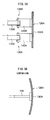
FIG. 5A is a depiction diagram indicating a support state of a guide plate according toexemplary embodiment 1 of the present invention;FIG 5B is a depiction diagram indicating a support state of a guide plate according to a comparative example. -
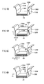
FIGS. 6A to 6D are depiction diagrams indicating a procedure that moves guide plates according toexemplary embodiment 1 of the present invention and places side by side the end surfaces of planographic printing plates. -
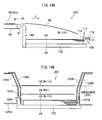
FIG. 7A is a partial block diagram of a processing line according toexemplary embodiment 2 of the present invention;FIG 7B is a partial cross sectional view along the width direction of a stacking apparatus included by the processing line. -
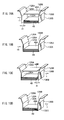
FIGS. 8A to 8D are depiction diagrams indicating a procedure that moves guide plates according toexemplary embodiment 2 of the present invention and places side by side the end surfaces of planographic printing plates. -
FIG. 9 is a cross sectional view in the width direction of the stacking apparatus according to exemplary embodiment 3 of the present invention. -
FIGS. 10A to 10D are depiction diagrams indicating a procedure that moves guide plates according to exemplary embodiment 3 of the present invention and places side by side the end surfaces of planographic printing plates. -
FIG. 11 is a cross sectional view in the width direction of the stacking apparatus according to exemplary embodiment 4 of the present invention. -
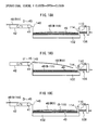
FIGS. 12A and 12B are side and front views indicating the movement of a pusher when (N-1)th to (N+1)th planographic printing plates are induced in the stacking apparatus according to exemplary embodiment 4 of the present invention. -
FIGS. 13A and 13B are side and front views indicating the movement of a pusher when (N-1)th to (N+1)th planographic printing plates are induced in the stacking apparatus according to exemplary embodiment 4 of the present invention. -
FIGS. 14A and 14B are side and front views indicating the movement of a pusher when (N-1)th to (N+1)th planographic printing plates are induced in the stacking apparatus according to exemplary embodiment 4 of the present invention. -
FIG.15 is a sectional view sectioned in a width direction of a sheet material stacking apparatus of a fifth embodiment of the present invention. -
FIG.16 is an expanded sectional view showing a detailed configuration of an oscillating mechanism of the sheet stacking apparatus of the fifth embodiment of the present invention. -
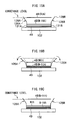
FIGS.17A and17B are explanatory views showing motions of guide plates of the sheet material stacking apparatus of the fifth embodiment of the present invention. -
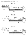
FIGS.18A to 18C are side views showing motions of the guide plate when the(N-1)th to the (N+!)th planographic printing plates are induced to the sheet material stacking apparatus of the fifth embodiment of the present invention. -
FIGS.19A to 19C are front views showing motions of the guide plate when the(N-1)th to the (N+!)th planographic printing plates are induced to the sheet material stacking apparatus of the fifth embodiment of the present invention. -
FIGS.20A to 20C are side views showing motions of the guide plate when the(N-1)th to the (N+!)th planographic printing plates are induced to the sheet material stacking apparatus of the fifth embodiment of the present invention. -
FIGS.21A to 21C are front views showing motions of the guide plate when the(N-1)th to the (N+!)th planographic printing plates are induced to the sheet material stacking apparatus of the fifth embodiment of the present invention. - There is set forth one example of the sheet material stacking apparatus of the present invention wherein the entire first guide member functions as the pusher.
-
FIGS. 1 and2 show a planographic printingplate processing line 10 wherein astacking apparatus 100 according to a first exemplary embodiment is included. - As shown in
FIG. 1 , a strip-conveying device 16 is disposed upstream (right-hand upper side inFIG. 1 ) of theprocessing line 10. - The strip-
conveying device 16 is detachably provided with aweb roll 14 in which astrip 12 of the material of a planographic printing plate is rolled in a roll-like fashion. In addition, the strip-conveying device 16 continuously conveys thestrip 12 downstream from theweb roll 14 at a speed corresponding to the line speed of theprocessing line 10. - The
strip 12 is conveyed to apressure roller 20 disposed downstream after correcting the curl is by aleveler 18. - The
pressure roller 20 crimps band-like protectingpaper 24 conveyed from an protectingpaper conveying device 22 to the upper surface of the strip 12 (photosensitive layer surface). At this time, the protectingpaper 24 crimped to thestrip 12 is charged by a charging apparatus (not shown) to be electrostatically crimped to thestrip 12. Anotcher 26 is disposed downstream of thepressure roller 20. - Although the case where the protecting
paper 24 is used is described in the exemplary embodiment, the protectingpaper 24 may not be used. - When changing the slit width of the
strip 12, thenotcher 26 punches at the central portion and at side portions close to both edges with respect to the width of thestrip 12 to form a notch portion of a predetermined shape at each of the central and side portions of thestrip 12. Thus, changing of the width of thestrip 12 is possible while simultaneously and continuously cutting thestrip 12 and protectingpaper 22. - A
slitter 28 that cuts thestrip 12 in a predetermined slit width is placed downstream of thenotcher 26. Additionally, downstream of theslitter 28, alength measuring apparatus 30 is placed that counts a conveyance length. - Here, after being cut in a predetermined slit width by the
slitter 28, the conveyance length of thestrip 12 is counted by means of thelength measuring apparatus 30 and thestrip 12 is cut by acutter 32 in a synchronous manner along the width direction of thestrip 12 when a count value counted by thelength measuring apparatus 30 reaches a predetermined count. Thereby, aplanographic printing plate 48 with a predetermined size is produced. - As shown in
FIG. 2 , downstream of thecutter 32, aconveying apparatus 36 constituted by a plurality ofbelt conveyers - In the
belt conveyer 34, a belt is stretched between a pair ofrollers 33 that are rotatably disposed and the belt is movable in the arrow F direction. Also in thebelt conveyer 42, a belt is stretched between a pair ofrollers 41 that are rotatably disposed and the belt is movable in the arrow F direction. - The
planographic printing plate 48 cut from thestrip 12 is conveyed downstream by means of thebelt conveyers - In some case, the
strip 12 can be separated into two in the width direction by the slitter 28 (seeFIG. 1 ) and cut by thecutter 32 into twoplanographic printing plates 48 simultaneously. Each of the twoplanographic printing plates 48 is distributed onto thedifferent belt conveyers 42 by means of a sorting gate or the like (not shown) disposed half way to the stacking apparatus(es) and then induced to the twostacking apparatuses 100 disposed in different positions. - On the other hand, a sorting
gate 40 for changing the conveyance destinations of theplanographic printing plates 48 is disposed between thebelt conveyer 34 and thebelt conveyer 42. - In case when the
planographic printing plate 48 cut from thestrip 12 is a sample, a rejected product, or the like, the sortinggate 40 distributes the correspondingplanographic printing plate 48 onto the belt conveyer for line-out 38. - The
belt conveyer 38 has a constitution in which a belt is stretched by a pair ofrollers 37 that are rotatably placed, and conveys theplanographic printing plate 48 that is a sample, rejected product, or the like to a retrieving box44 disposed downstream. - In the terminal of the conveying
apparatus 36 is placed a stackingapparatus 100 of stacking a plurality of theplanographic printing plates 48. - Just in front of the stacking
apparatus 100 and above thebelt conveyer 42, asensor 45 detecting the passage of the tip of theplanographic printing plate 48 that has been conveyed is disposed. - The
sensor 45 is a reflection-type optical sensor and detects the passage of the tip of theplanographic printing plate 48 on the basis of the amount of reflection light received. In addition, thesensor 45 is connected to acontrol apparatus 47 controlling the driving of each portion of the stackingapparatus 100 on the basis of a detecting signal from thesensor 45. - Next, the stacking
apparatus 100 will be described. - As indicated in
FIG. 2 , the stackingapparatus 100 has a flat planar stacking base 102(sheet material stacking base). - The top face of the stacking
base 102 is a flat planar stackingface 103 on which theplanographic printing plates 48 are stacked. Additionally, the stackingbase 102 is supported by alifter 104. - The
lifter 104 lifts the stackingbase 102 along the thickness direction of theplanographic printing plate 48 in such a way that the height of the uppermost surface of theplanographic printing plate 48 is always constant in accordance with a signal from a level sensor (not shown) for detecting the height of the uppermost surface of theplanographic printing plates 48 stacked on the stackingface 103. - A
back stopper 106 is disposed downstream of the stackingbase 102 with respect to the conveyance direction of theplanographic printing plate 48, and afront stopper 146 is placed upstream of the stackingbase 102. - In the
back stopper 106, astopper plate 108 is disposed so as to face the end surface of theplanographic printing plates 48 stacked on the stackingface 103. - The
stopper plate 108 is constituted of abase portion 110 formed of a metal plate or plastic plate and acushion pad 114 foxed in thebase portion 110. Thecushion pad 114 is disposed so as to be in contact with the end surface of theplanographic printing plate 48. - On the surface of the
cushion pad 114 of the stopper plate 108 a receivingplate 112 projects so as to temporarily receive the end portion of theplanographic printing plate 48. - The receiving
plate 112 is a planar member that is inclined downward toward the stackingbase 102. The angle of inclination of the receivingplate 112 relative to the horizontal face is preferably from about 15 to 30 degrees, and is arbitrarily set in accordance with the properties and induction speed of theplanographic printing plate 48. - The surface of the receiving
plate 112 that is on the side that the planographic printing plates contact can be covered with a soft material such as a polyamide resin (trade name: MC NYLON), high-density polyethylene resin, polypropylene resin or fluorine resin. - On the back side (opposite side to the cushion pad 114) of the
base portion 110 of thestopper plate 108, acylinder 116 is placed for supporting thestopper plate 108 and declining the impact from theplanographic printing plate 48. - The
cylinder 116 is fixed to the flame or floor of theprocessing line 10 or the like via a bracket (not shown) so that the positional relation of thecylinder 116 to thebelt conveyer 42 is not varied. - The
cylinder 116 slidably supports arod 118 along the conveyance direction and the tip of therod 118 is connected and fixed to thebase portion 110. - On the outer periphery of the
rod 118, acoil spring 120 in a compressed state is disposed. Thecoil spring 120 urges thestopper plate 108 in the direction opposite to the conveyance direction of thestopper plate 108. - Here, the position of the
cylinder 116 is adjustable along the conveyance direction. Thus, the position of thestopper plate 108 in the conveyance direction can be adjusted according to the length along the conveyance direction of theplanographic printing plates 48 that are to be stacked on the stackingbase 102. - On the other hand, as shown in
FIGS. 2 and3 , thefront stopper 146 is substantially rectangular parallelepiped-shaped and hollow and is disposed such that the thickness direction thereof is according to the conveyance direction and the longitudinal direction thereof is according to the width direction of the stackingbase 102. - The top end of the
front stopper 146 is slightly lower than the top surface of thebelt conveyer 42 and the end of the downstream side thereof is processed in an R-shaped manner. In addition, on the inner side face of the downstream side of thefront stopper 146 positions theplanographic printing plate 48 induced onto the stackingbase 102 along the conveyance direction. - A plurality of slit-
like nozzles 140 narrowly elongated in the width direction are formed at the top portion of the inner face of thefront stopper 146. Inside of thefront stopper 146, air piping (not shown) for supplying air to each of thenozzles 140 is placed, and air is blasted from the plurality of thenozzles 140 during stacking theplanographic printing plates 48. - Accordingly, an air layer is formed between the
planographic printing plate 48 and the stackingface 103 or between the consecutive towplanographic printing plates 48 just after the induction of theplanographic printing plate 48 from thebelt conveyer 42, and the movement resistance of theplanographic printing plate 48 that moves (slides) on the stackingface 103 by the inertia force is restrained. - Below the
nozzle 140, a receivingplate 144 temporarily supporting from below the end of theplanographic printing plate 48 induced by thebelt conveyer 42 is provided. - As the receiving
plate 112, the receivingplate 144 is a planar member inclined downward toward the stackingbase 102. The inclination angle of the receivingplate 144 with respect to the horizontal surface, as in the receivingplate 112, is preferably from about 15 to 30 degrees. However the inclination angle may be set according to the properties and induction speed of theplanographic printing plate 48. - As the receiving
plate 112, the upper surface of the receiving plate may be covered with a soft material such as AC NYLON, high molecular weight polyethylene resin, polypropylene resin or fluorine resin, and the tip thereof may be bent downward. - As shown in
FIGS. 3 and4 , the stackingapparatus 100 comprises side guides 122A, 122 disposed beside the end surfaces of both (left and right-hand) sides of the stackingbase 102. - The side guide 122A is constituted of a
case 125A havinghollow portion 124A inside thereof, aguide plate 126A forming one side wall of thecase 125A and face the left end surface of the stackedplanographic printing plates 48, and a guideplate driving portion 136 motioning theguide plate 126A to contact or separate from theplanographic printing plates 48. - The
guide plate 126A comprises avertical portion 130A facing an end surface of a bundle 49 (sheet bundle) of theplanographic printing plates 48, aninclined portion 128A disposed on top of thevertical portion 130A so as to be inclined at an angle θ with respect to the vertical direction, and aflat portion 132A protruding outward from the top of theinclined portion 128A. The angle θ is preferably from 0 degree to 60 degrees, more preferably from 0 degree to 40 degrees, from the vertical face. - The
guide plate 126A is formed of a stainless steel plate, and accordingly, has a sufficient strength so as not to be distorted by impact load from theplanographic printing plates 48. - The guide
plate driving portion 136 comprises arotator 137, afirst link member 138, asecond link member 139, asupport member 142, a holdingmember 141, and abase 140. - The
rotator 137 is rotatably supported by a bracket or the like (not shown) and reciprocally rotated in the arrow R direction by means of a motor (not shown) driven by thecontrol apparatus 47 disposed in the proximity of the stackingapparatus 100. In addition, the above-mentioned sensor 45 (seeFIG. 2 ) is connected to thecontrol apparatus 47 and thecontrol apparatus 47 drives the motor upon counting a predetermined time when a detecting signal is sent from thesensor 45. - The
first link member 138 is fixed to therotator 137 by adhesion or welding, and reciprocally rotated together with therotator 137. - One end the
second link member 139 is rotatably connected to the end of thefirst link member 138 by a pin and the other end thereof is rotatably connected to the end of thesupport member 142 by a pin. - The
support member 142 is constituted of a substantially L-shaped steel plate and a portion thereof that is bent in the vertical direction is fixed to the back side of thevertical portion 130A of theguide plate 126A by welding or the like. - The holding
member 141 is fixed on the base 140 fixed on the inner side of thehousing 125A and its arm portion horizontally protruded in a predetermined interval supports thesupport member 142 movably in the horizontal direction (sliding). - Here, when the
rotator 137 andfirst link member 138 rotate counterclockwise, the left-hand end of thesecond link member 139 moves upper leftward and also the right-hand end of thesecond link member 139 moves to the left. Thus, thesupport member 142 moves leftward and accordingly, theguide plate 126A moves leftward so as to separate from the left end surface of theplanographic printing plate 48. - When the
rotator 137 andfirst link member 138 rotate clockwise, the left end of thesecond link member 139 moves lower rightward and also the right-hand end of thesecond link member 139 moves rightward. Thus thesupport member 142 moves rightward and accordingly, theguide plate 126A moves rightward so as to contact the left end surface of theplanographic printing plate 48. - On the other hand, the
side guide 122B is constituted of ahousing 125B having formed therein ahollow portion 124B and aguide plate 126B that forms one side wall of thehousing 125B and faces the right-hand end surface of the stackedplanographic printing plates 48. - The
guide plate 126B is placed in the vertical direction and constituted of avertical portion 130B oppose the end surface of a bundle of theplanographic printing plates 48, aninclined portion 128B inclined at an angle θ with respect to the vertical direction on top of thevertical portion 130B, and aflat portion 132B protruded outward from the top of theinclined portion 128B. The angle θ is, as in the above-mentionedguide plate 126A, preferably from 0 degree to 40 degrees from the vertical face. - The
guide plate 126B is formed of a stainless steel plate and has a sufficient strength so as not to be distorted even when receiving impact load from theplanographic printing plates 48. - A hard coat is formed on the inner surfaces of the
guide plates planographic printing plates 48 abut. - The surface hardness of the hard coat is higher than that of stainless steel that is a base material of the
guide plates planographic printing plate 48 is smaller than the friction resistance between the base material and theplanographic printing plate 48, specifically preferably 0.2 or smaller. - The hard coat includes a rigid chromium plated coat, diamond-like carbon (DLC) coat, and the like. The diamond-like carbon coat (DLC coat) may be formed by, for example, treating the
guide plates - Here, in the present exemplary embodiment, the
guide plate 126B is fixed to thehousing 125B with a not-shown bolt. In addition, thehousings - The guide
plate driving portion 136, as depicted inFIG. 5A , is disposed in two sites along the width direction of theguide plate 126A; theguide plate 126A is supported bysupport members guide plate 126A is supported at a plurality of points and accordingly, deformation of theguide plate 126A can be prevented and thevertical portion 130A is kept flat. - As a comparative example,
FIG. 5B shows an embodiment wherein theguide plate 126A is supported at one point by thesupport member 135. Since theguide plate 126A is supported only at one point in the above embodiment, theguide plate 126A can be deformed at the end portions thereof, and thus, theguide plate 126A is preferably supported at a plurality of points. - Next, the operation of
exemplary embodiment 1 of the present invention will be described. - First, the positioning (sorting end surfaces side by side) of the conveyance direction of the
planographic printing plate 48 induced into theaccumulation base 102 along the conveyance direction thereof is described. - As shown in
FIG. 3 , firstly, theplanographic printing plate 48 is induced onto theaccumulation base 102 by thebelt conveyer 42. At the time of induction of theplanographic printing plate 48, air is blasted from thenozzle 140 of thefront stopper 146 and the friction resistance of the newly inducedplanographic printing plates 48 and the stackingface 103 or theplanographic printing plates 48 already stacked is reduced. - The stacking
face 103 or theplanographic printing plates 48 already stacked are maintained at a constant height by thelifter 104. Thus, eachplanographic printing plate 48 that is induced one by one via thebelt conveyer 42 lands at substantially a same position regardless of the number of sheets of theplanographic printing plates 48 on the stackingface 103. - The
planographic printing plate 48 induced onto the stackingface 103 contacts theback stopper 106 on the tip faces thereof. Thestopper plate 108 receiving impact caused by contact of theplanographic printing plate 48 moves in the conveyance direction while compression deforming thecoil spring 120 and at the same time receives a damping force from thecylinder 116. Thus, the movement of theplanographic printing plate 48 to the conveyance direction ceases. - At the
back stopper 106, therod 118 elongates by recovering force of thecoil spring 120 so as to urge theplanographic printing plate 48 toward thefront stopper 146 through thestopper plate 108. Accordingly, the back end surface of theplanographic printing plate 48 contacts thefront stopper 146. - Thus, the
planographic printing plate 48 is positioned along the conveyance direction. - The
planographic printing plate 48 positioned in the conveyance direction drops toward the stackingface 103. At this time, theplanographic printing plate 48 drops onto the stackingface 103 in a state of being supported from below by the receivingplates planographic printing plate 48 contacts theplanographic printing plates 48 that are already stacked, at the central portion and then, at the end portion, due to the weight thereof. - Next, the positioning in the width direction (direction orthogonal to the conveyance direction) of the planographic printing plates 48 (end surface-sorting) will be described.
- As shown in
FIG. 6A , before theplanographic printing plate 48 is induced (seeFIG. 3 ), theguide plates bundle 49 of theplanographic printing plates 48 locating at both ends with respect to the width direction thereof and both end surfaces of theplanographic printing plates 48 are sorted. In the above state, the distance between theguide plate 126A and theguide plate 126B is the same as the width of theplanographic printing plate 48, and is set as the reference position. Here, thebundle 49 corresponds to the sheet bundle of the present invention. - Subsequently, as shown in
FIGS. 2 ,4 and6B , thesensor 45 detects the passage of the tip of theplanographic printing plate 48 on thebelt conveyer 42. On the basis of the detecting signal, the above mentionedcontrol apparatus 47 drives the guideplate driving portion 136 and theguide plate 126A moves in the arrow X direction. The position at which theguide plate 126A is in non-contact with the end surface of the planographic printing plate 48 (left side in the drawing) is set to be the separating position. - Here, given the reference position is 0, the range of the displacement of the
guide plate 126A is preferably from 0 to +10 mm or less. In addition, as the correction, the displacement may be preferably changed in a length of about -2 to -3 mm. - Subsequently, in a state in which the
guide plate 126A is at the separating position and disposed at an interval of the distance d1 from the end surface of thebundle 49, theplanographic printing plate 48 is induced. Thus, theplanographic printing plate 48 is not caught by theguide plates - Here, when the
planographic printing plate 48 drops in a condition that the central position thereof is consistent with the central position of thebundle 49, each end surface of theplanographic printing plate 48 would be consistent with each of the end surfaces of thebundle 49. However, when theplanographic printing plate 48 drops in a condition that the central positions are displaced, as shown inFIG. 6C , it is stacked in a state in which theplanographic printing plate 48 protrudes in a distance of d2 from the other end-surface of the bundle 49 (left side in the drawing). - Subsequently, as shown in
FIG. 6D , thecontrol apparatus 47 drives the guideplate driving portion 136 in a predetermined time passage from the detection of theplanographic printing plate 48 and theguide plate 126A moves to the arrow +X direction. Theguide plate 126A contacts the other end-surface (left side in the drawing) of theplanographic printing plate 48 and moves theplanographic printing plate 48 toward theguide plate 126B. - In the
planographic printing plate 48, the other end-surface (left side in the drawing) is urged by theguide plate 126A and the one end-surface (right-hand side in the drawing) contacts theguide plate 126B. Thus the end surfaces of theplanographic printing plate 48 are sorted with the end surfaces of thebundle 49. - The period of the movement of the X direction of the
guide plate 126A is set at 0.1 second to 1 second (10 Hz or less in frequency). - As described above, when the
planographic printing plate 48 is induced from thebelt conveyer 42, the guideplate driving portion 136 drives theguide plate 126A, thereby displacing theguide plate 126A to the separating position. Theplanographic printing plate 48 stacks onto the stackingbase 102 without being caught by theguide plates - Thereafter, the
guide plate 126A varies to the reference position, at which position, theguide plate 126A contacts the other end-surface of the planographic printing plate 48(left side in the drawing) so as to sort both end surfaces extending at the ends of theplanographic printing plate 48 stacked on the stackingbase 102 with respect to the width direction thereof. - Because the
inclined portions guide plates planographic printing plate 48 sometimes contacts theguide plate 126A or guideplate 126B, theplanographic printing plate 48 contacts theinclined portion base 102. Consequently, theplanographic printing plate 48 is not caught on the way. - Since the
control apparatus 47 synchronizes the timing of the detection in thesensor 45 and drives the guideplate driving portion 136 thereby varying theguide plate 126A, theplanographic printing plate 48 can be induced onto the stackingbase 102 when theguide plate 126A and guideplate 126B separate from each other. - The
guide plate 126A is driven by the guideplate driving portions planographic printing plates 48 without the deformation of theguide plate 126A, whereby the end surfaces of theplanographic printing plates 48 are sorted. - Vibration is given to the
inclined portion 128B of theguide plate 126B of the reference guide (fixed guide) by means of a vibrator or the like, whereby theplanographic printing plate 48 may not be caught by theguide plate 126B. - Next, another example of the sheet material stacking apparatus of the present invention wherein the whole part of the first guide member functions as a pusher will be described. In addition, to the components that are basically the same as those in the
exemplary embodiment 1, the same numerals as given inexemplary embodiment 1 are given and the descriptions thereof will be omitted. - As shown in
FIGS. 7A and 7B , upward of thebelt conveyer 42, asensor 150 is disposed so as to detect the speed of theplanographic printing plate 48 conveyed by thebelt conveyer 42. - The
sensor 150 is an optical sensor similar to the sensor 45 (seeFIG. 2 ) inexemplary embodiment 1 and connected to acontrol apparatus 152 of determining the speed of theplanographic printing plate 48 and moving theguide plate 126A. - The
control apparatus 152 counts the passage time that is a time from the passage of the tip of theplanographic printing plate 48 to the passage of the rear end thereof on the basis of detection signals from thesensor 150 and divides a length of theplanographic printing plate 48 by the passage time to obtain the passage speed (conveyance speed). - On the other hand, a stacking
apparatus 160 is disposed downstream of thebelt conveyer 42. - The stacking
apparatus 160 comprises the above mentioned backstopper 106 andfront stopper 146 in the conveyance direction of theplanographic printing plate 48. - In addition, the stacking
apparatus 160 also comprises a pair of side guides 162 facing end surfaces of theplanographic printing plate 48 locating at both ends with respect to the width direction thereof. In addition, among the side guides 162 provided at the both sides of thebundle 49 of theplanographic plates 48, theside guide 162 sitting in the right side of thebundle 49 has the same constitution as the above mentionedside guide 122B (seeFIG. 3 ), and accordingly, the description of the constitution of the right-hand side guide 162 is omitted. - The
side guide 162 sitting in the left side of thebundle 49 is constituted of ahousing 164 having ahollow portion 166 formed therein, the above mentionedguide plate 126A (seeFIG. 4 ), and a guideplate driving portion 168 contacting theguide plate 126A withplanographic printing plates 48 or separating it therefrom. - The guide
plate driving portion 168 is a piston-type air vibrator and comprises a base 170 fixed inside of thehousing 164, apiston portion 172 disposed on the base 170 toward theguide plate 126A and asupport plate 174 fixed to one end of thepiston portion 172. - The
support plate 174 is fixed to the backside of theguide plate 126A by adhesion or the like. - The
piston portion 172 may be supplied with air by an air supplying portion (including a regulator and electromagnetic valve, not shown) and is connected to thecontrol apparatus 152. - The
control apparatus 152 selects one frequency according to the velocity of theplanographic printing plate 48 detected by thesensor 150 from a group of predetermined different frequencies and vibrates theguide plate 126A according to the selected frequency. In the present exemplary embodiment, the frequency of theguide plate 126A is set at about 50 Hz. - A speed matrix that is a relation between a conveyance speed of the
planographic printing plate 48 and a timing of displacement of theguide plate 126A may be memorized in thecontrol apparatus 152 in advance to determine the timing of the displacement of theguide plate 126A from a measured conveyance speed of theplanographic printing plate 48 on the basis of the matrix speed. - Thus, when the
control apparatus 152 drives the air supplying portion, air is supplied to thepiston portion 172, whereby theguide plate 126A vibrates in the arrow X direction. - Next, the operation of
exemplary embodiment 2 of the present invention will be described. However, the positioning of theplanographic printing plate 48 in the conveyance direction (sorting end surfaces of the planographic printing plate 48) induced into the stackingbase 102 is performed in the same manner as theexemplary embodiment 1, and thus, the explanation of the positioning is omitted. - As shown in
FIG. 8A , before theplanographic printing plate 48 is induced (seeFIG. 3 ), theguide plates bundle 49 of theplanographic printing plates 48 located at the end with respect to the width direction thereof, and thus, both end surfaces of theplanographic printing plates 48 are sorted. The position in this state is referred to the reference position. - Subsequently, as shown in
FIG. 7 , thesensor 150 detects the passages of the tip and back end portion of theplanographic printing plate 48 on thebelt conveyer 42. On the basis of the detecting signals, thecontrol apparatus 152 drives the guideplate driving portion 168 and starts to vibrate theguide plate 126A. - The
guide plate 126A vibrates synchronously with the conveyance speed of theplanographic printing plate 48 and, as shown inFIG. 8B , theplanographic printing plate 48 is induced when theguide plate 126A moves by a distance of d3 in the arrow -X direction. The position of the state is referred to the separating position. In addition, the distance of displacement of the distance d3 is the same as the distance d1 in theexemplary embodiment 1. - Subsequently, as shown in
FIG. 8C , theguide plate 126A moves in the arrow +X direction. Theguide plate 126A contacts the other end-surface of the planographic printing plate 48 (left side in the drawing) and moves theplanographic printing plate 48 toward theguide plate 126B. - Subsequently, as shown in
FIG. 8D , the other end-surface of the planographic printing plate 48 (left side in the drawing) is urged by theguide plate 126A and the one end-surface (right side in the drawing) contacts theguide plate 126B. Thus, both end surfaces of theplanographic printing plate 48 are sorted with the end surfaces of thebundle 49. - The step is repeated and the
guide plate 126A continuously vibrates between the reference and separating positions, and accordingly, theplanographic printing plate 48 drops without being caught between theguide plates planographic printing plate 48 is induced, both end surfaces of the nextplanographic printing plate 48 are similarly sorted. - As described above, the
control apparatus 152 selects a frequency of the displacement of theguide plate 126A synchronously with the conveyance speed of theplanographic printing plate 48 on thebelt conveyer 42, controls the driving of the guideplate driving portion 168 according to the selected frequency, and vibrates theguide plate 126A. - Thus, even when the
planographic printing plates 48 are continuously induced onto the stackingbase 102, theplanographic printing plate 48 can be induced when theguide plate 126A is separated from theguide plate 126B, and thus, both end surfaces of theplanographic printing plates 48 can be sorted without theplanographic printing plates 48 being caught by theguide plate - Next, still another example of the sheet material stacking apparatus of the present invention in which the whole part of the first guide member serves as a pusher will be described. To the components that are basically the same as those in the
exemplary embodiment 1, the same numerals as given in theexemplary embodiment 1 are given, and the explanation of the components are omitted. - In the exemplary embodiment, a stacking
apparatus 180 instead of the stackingapparatus 100 is disposed downstream of thebelt conveyer 42 that is indicated inFIG. 2 . - As shown in
FIG. 9 , the stackingapparatus 180 has placed therein side guides 182A, 182B outside both sides of the end surfaces of the stacking base 102 (left and right-hand), respectively. - Here, the side guides 182A, 182B have a configuration having the same members symmetrically disposed, and therefore, the descriptions of the right-
hand side guide 182B are omitted. However, as required in description, the letter 'B' is attached to the numerals of the components of theright side guide 182B. - The side guide 182A comprises a
housing 184A having ahollow portion 186A formed therein, the above mentionedguide plate 126A that forms one side wall of thehousing 184A and is displaced so as to oppose the left surface of the stackedplanographic printing plates 48 and the above mentioned guideplate driving portion 136 for contacting or separating theguide plate 126A from theplanographic printing plates 48. - Next, the operation of exemplary embodiment 3 of the present invention will be described. However, the positioning of the
planographic printing plate 48 in the conveyance direction (sorting end surfaces) induced into the stackingbase 102 is performed in the same manner as theexemplary embodiment 1, and therefore, the description of the positioning is omitted. - Before the
planographic printing plate 48 is induced (seeFIG. 3 ), theguide plates bundle 49 of theplanographic printing plates 48 located at the ends with respect to the width direction thereof and both end surfaces of theplanographic printing plates 48 are sorted. - Subsequently, as shown in
FIGS. 2 ,9 ,10A , thesensor 45 detects the passage of the tip of theplanographic printing plate 48 on thebelt conveyer 42. On the basis of the detecting signal, the above mentionedcontrol apparatus 47 drives the guideplate driving portion 136A and moves theguide plate 126A by the distance d4 in the arrow -X direction. Additionally, the distance d4 is the same as the above mentioned distance d1. - The
planographic printing plate 48 is induced in a state wherein theguide plate 126A is separated from the end surface in a distance of the bundle, so that theplanographic printing plate 48 is not caught by theguide plates - Subsequently, as shown in
FIGS. 9 and10B , thecontrol apparatus 47 drives the guideplate driving portion 136A in a predetermined time after the detection of theplanographic printing plate 48 and moves theguide plate 126A in the arrow +X direction. Theguide plate 126A contacts the other end-surface of the planographic printing plate 48 (left side in the drawing) and moves theplanographic printing plate 48 toward theguide plate 126B. - The other end-surface (left side in the drawing) of the
planographic printing plate 48 is urged by theguide plate 126A and the one end-surface (right-hand in the drawing) thereof contacts theguide plate 126B. Thus both end surfaces of theplanographic printing plate 48 are sorted with those of thebundle 49. In addition, the period of the movement of the X direction of theguide plate 126A is set at 0.1 to 1 second (10 Hz or less in frequency). - Subsequently, as shown in
FIGS. 2 ,9 and10C , thesensor 45 detects the passage of the tip of theplanographic printing plate 48 on thebelt conveyer 42. On the basis of the detecting signal, the above mentionedcontrol apparatus 47 drives the guideplate driving portion 136B and moves theguide plate 126B in the arrow +X direction. - When the
guide plate 126B separated from the end surface of the bundle 49 (right-hand side in the drawing) in the distance d4, theplanographic printing plate 48 is induced. - Subsequently, as shown in
FIGS. 9 and10D , the above mentionedcontrol apparatus 47 drives the guideplate driving portion 136B in a predetermined time after the detection of theplanographic printing plate 48 and moves theguide plate 126B in the arrow -X direction. Theguide plate 126B contacts one end-surface of the planographic printing plate 48 (right-hand side in the drawing) and moves theplanographic printing plate 48 toward theguide plate 126A. - In the
planographic printing plate 48, the one end-surface (right side in the drawing) is urged by theguide plate 126B, and the other end-surface (left side in the drawing) contacts theguide plate 126A. Thus, both end surfaces of theplanographic printing plate 48 are sort with thebundle 49. - The sheet material stacking apparatus of the exemplary embodiment 3 can be used for stacking sheet materials other than the
planographic printing plates 48, such as recording paper. - The guide
plate driving portion 136 may also be a motor driven cam system. - The guide
plate driving portion 168 may also be a turbine-type air vibrator. When employing a turbine-type air vibrator, the frequency can be from 100 to 300 Hz. - An example of the sheet material stacking apparatus of the present invention having a configuration that the first geode member is separated into a guide portion that is fixed at a separating position and a pusher located below the guide portion. To the components basically the same as those in
exemplary embodiment 1 are given the same numerals as given inexemplary embodiment 1 and the descriptions of the components are omitted. - As shown in
FIG. 11 , in a sheetmaterial stacking apparatus 200 according to exemplary embodiment 4, the first guide member is separated into aguide plate 126A corresponding to a guide member of the present invention and apusher 226 located below theguide plate 126A. The height of the stackingbase 102 is controlled in such a manner that both the lower edge of theguide plate 126A and theupper edge 226A of thepusher 226 are higher than thetop face 133 of thebundle 49. -
Cushion pads guide plate 126A and thehousing 125A and between theguide plate 126B and thehousing 125B. - The
pusher 226 reciprocatively moves the separating position indicated by a solid line inFIG. 11 and the reference position indicated by a two-dot chain line by means of apusher driving portion 236 accommodated inside of thehousing 125A. The distance between thepusher 226 and theguide plate 126B corresponding to the second guide portion of the present invention is equal to the width D of theplanographic printing plate 48 at the reference position and equal to the length that is an addition of the displacement A of thepusher 226 to the width D of theplanographic printing plate 48 at the separating position. - The
pusher driving portion 236 has a construction similar to that of theguide driving portion 136 inexemplary embodiment 1 to 3 and is driven by a control apparatus 147. To the control apparatus 147, the sensor 45 (seeFIG. 2 ) is connected. When a detecting signal is sent from thesensor 45, the control apparatus counts a predetermined time and drives a motor for driving thepusher driving portion 236. - Except the respects mentioned above, the stacking
apparatus 200 has a construction similar to that of the stackingapparatus 100 ofexemplary embodiment 1. - Hereinafter, the operation of the stacking
apparatus 200 will be set forth by way of example when the (N-1)thplanographic printing plate 48, the Nthplanographic printing plate 48 and the (N+1)thplanographic printing plate 48 are induced. - As shown in
FIGS. 12A and 12B , the Nthplanographic printing plate 48 that is induced next to the (N-1)thplanographic printing plate 48 is conveyed by thebelt conveyer 42 along the conveyance direction 'a'. When the tip of the Nthplanographic printing plate 48 is detected by thesensor 45, themotor 137 is switched on T second(s) after the detection time and starts to rotate. - At a time when the time 't' elapses from the time point when the
sensor 45 detects the tip of the Nthplanographic printing plate 48 and, as shown inFIGS. 13A and 13B , the (N-1)thplanographic printing plate 48 contacts the surface of thecushion pad 114 of theback stopper 106. At the same time, thepusher 226 is located at the reference position and guides the (N-1)thplanographic printing plate 48 that is to be induced onto thebundle 49 upward of thebundle 49. In addition, the time t may be obtained a priori as a time from the time when thesensor 45 detects the tip of the Nthplanographic printing plate 48 to the time when the tip of the (N-1)thplanographic printing plate 48 contacts thecushion pad 114 of theback stopper 106. Additionally, the time T is determined so that the equation t = T + tm is satisfied, wherein tm is the time of themotor 137 traveling halfway around and that is, the time needed for thepusher 226 to move from the separating position to the reference position. - The
motor 137 continues rotating and, as shown inFIGS. 14A and 14B , thepusher 226 returns to the separating position. At the time when the pusher returns to the separating position, the (N-1)thplanographic printing plate 48 is stacked on thebundle 49, the Nthplanographic printing plate 48 is being induced toward the bundle of theplanographic printing plates 49, and the tip of the next (N+1)thplanographic printing plate 48 is detected by thesensor 45. - An example of the sheet material stacking apparatus of the present invention wherein the first and second guide members are in an open position, that is, both guide members separate away, or a closed position, that is, the both guide members come closer to each other is described in the following example embodiment. To the component basically similar to those of
Exemplary Embodiment 2, the same numerals as those inExemplary Embodiment 2 are given and explanation of the components are omitted. - As shown in
FIG.15 , in a sheetmaterial stacking apparatus 202 relating to Exemplary 5,guide plates perpendicular portions inclined portions perpendicular portions perpendicular portions inclined portions - The
guide plates housings perpendicular portions FIG. 15 , theguide plates perpendicular portions guide plates perpendicular portions planographic printing plate 48 that is a measurement thereof in a direction perpendicular to the conveyance direction and a sheet-sorting tolerance that is a tolerable amount of protrusion in the width direction of theplanographic printing pates 48 upon stacking. The controlling width is generally set at a length about 1mm wider than the width of theplanographic printing plate 48. - Inside of the
housings mechanisms - As shown in
FIGS.15 and16 , each of theoscillating mechanisms motor 337, crank 338 rotated by themotor 337,rockers crank 338, and atransmission rod 341 that transmits the movement of therocker 340 to theguide plates transmission rod 341 is attached pivotably onto the backside surfaces of theinclined portions guide portions inclined portions planographic printing plates 48 contact. The crank 338 and therocker 339 are connected with each other by apin 342, therocker 339 and therocker 340 are connected with each other by apin 343, and therocker 340 and thetransmission rod 341 are connected with each other by apin 344. Therocker 340 is also connected with the inside wall of thehousing pin 345. - As shown by an arrow 'a' in
FIGS. 15 and16 , when thecrank 338 rotate around anaxis 337A of themotor 337, therocker 339 makes a reciprocal motion to an extent shown by the solid line and the alternate long and two short dash line. Accordingly, therocker 340 pivots around thepin 345 as shown by arrows 'b' and 'c', and thus, thetransmission rod 341 makes a reciprocal movement. Consequently, theguide plates 126Ainclined portions transmission rod 341 so as to oscillates pivotally as shown by the solid line and the alternate long and two short dash line inFIG.15 . Additionally, in theoscillating mechanisms motor 337 is controlled by the control apparatus 147 so that theguide plates - As shown in
FIG.17A , theguide plates belt conveyer 42 throws theplanographic printing plate 48 onto the stackingbase 102, theguide plates 126 and 126B are in a closed position, wherein theguide plates 126 and 126B are close to each other, then, during the time when theplanographic printing plate 48 is dropping between theguide plates guide plates guide plates 126 and 126B separated from each other so as to prevent theplanographic printing plate 48 from being stuck between theperpendicular portions planographic printing plate 48 is dropping between theperpendicular portions guide plates 126A and 126 return to the close position so as to guide theplanographic printing plates 48 to a predetermined point above the stackingbase 102. - As shown in
FIG. 17B , theguide plates belt conveyer 42 throws theplanographic printing plate 48 onto the stackingbase 102, theguide plates 126 and 126B are in an open position, wherein theguide plates 126 and 126B are open from each other, then, during the time when theplanographic printing plate 48 is dropping between theguide plates guide plates guide plates 126 and 126B are close to each other so as to guide theplanographic printing plates 48 to a predetermined point above the stackingbase 102. Finally, when theplanographic printing plate 48 is stacked on the stackingbase 102, theguide plates 126A and 126 return to the open position. - Except the above respects, the shacking
apparatus 202 has the same constitution as that of the stackingapparatus 180 of Exemplary Embodiment 3. - In the following, the function of the stacking
apparatus 202 is described by explaining the operation thereof in the case when (N-1)th, Nth and (N+1)thplanographic printing plates 48 are induced consecutively. Firstly, the operation of the stackingapparatus 202 wherein theguide plates 126A and 126 are oscillated in the motion scheme of closed, open, and then closed when theplanographic printing plate 48 is induced is described. - As shown in
FIGS.18A, 18B ,19A, 19B , the Nthplanographic printing plate 48, which is the next to the (N-1)thplanographic printing plate 48, is conveyed by thebelt conveyer 42 in the conveyance direction 'a' and the tip thereof is detected by thesensor 45, then, themotor 337 initiates rotation and theguide plates - Therefore, when the
sensor 45 detects the tip of the Nthplanographic printing plate 48, as shown inFIGS. 18A and19A , theguide plates planographic printing plate 48 is dropping between theinclined portions FIGS, 18B and19B , the guide portions pivots toward the open position, and then, while the Nthplanographic printing plate 48 is dropping between theperpendicular portions bundle 49, as shown inFIGS. 18C and19C , theguide plates planographic printing plate 48 is guide toward a predetermined position on the stackingbase 102 and sorted. - Secondly, the operation of the stacking
apparatus 202 wherein theguide plates 126A and 126 are oscillated in the motion scheme of open, closed, and then open when theplanographic printing plate 48 is induced is described. - As shown in
FIGS 20A, 20B ,21A, and 21B , the Nthplanographic printing plate 48, which is the next to the (N-1)thplanographic printing plate 48, is conveyed by thebelt conveyer 42 in the conveyance direction 'a' and the tip thereof is detected by thesensor 45, then, themotor 337 initiates rotation and theguide plates - Thus, when the
sensor 45 detects the tip of the Nthplanographic printing plate 48, as shown inFIGS. 20A and21A , theguide plates planographic printing plate 48 is dropping between theinclined portions FIGS, 20B and21B , the guide portions pivots toward the closed position, and then, while the Nthplanographic printing plate 48 is dropping between theperpendicular portions bundle 49, as shown inFIGS. 20C and21C , theguide plates - As described above, according to a sheet material stacking apparatus of the present invention, both end surfaces of a sheet material at the ends thereof with respect to the width direction may be sorted while stacking the sheet material on the sheet material stacking base.
- Generally, when a sheet material is induced onto a sheet material stacking base by means of a sheet material conveying unit,.
- Now, in a sheet stacking apparatus of the present invention, when a sheet is induced, the driving unit is driven, whereby the pusher is displaced until it reaches a separating position untouched with the other end-surface of the sheet material.
- This accumulates the sheet material on the sheet material stacking base without being caught by the first and second guide members.
- Thereafter, the displacement of the pusher to the reference position at which the pusher contacts the other end-surface of the sheet material in the width direction causes one end-surface of the sheet material in the width direction to contact the second guide member, thereby being capable of placing side by side both end surfaces located at the end of the sheet materials with respect to the width direction thereof stacked on the sheet material stacking base.
- A second aspect of the present invention relates to the sheet material stacking apparatus according to the first aspect wherein the height of the sheet material stacking base is controlled such that the height of the top face of a sheet bundle formed by accumulation of sheet materials on the sheet stacking base is lower than the height of the top edge of the pusher.
- In the sheet material stacking apparatus of the second aspect, a sheet material induced onto the sheet stacking base is definitely positioned by means of the pusher and the first guide member, and then placed on a sheet bundle.
- A third aspect of the present invention relates to the sheet material stacking apparatuses according to the first or second aspects, wherein the first guide member is formed such that the whole part of the first guide member serves as a pusher.
- According to the sheet material stacking apparatus of the third aspect, since the whole part of the first guide member is a pusher, the construction of the sheet material stacking apparatus is simple.
- A forth aspect of the present invention relates to the sheet material stacking apparatus according to the first or second aspect, wherein the first guide member is separated into a guide portion fixed at a separating position in which the distance between the first and second guide members is larger than the width of the sheet material and a pusher located downward of the guide portion.
- In the sheet material stacking apparatus of the forth aspect, a sheet stacking frame is formed of the guide portion included in the first guide member and the second guide member. Accordingly, the width of the sheet stacking frame is larger than the width of the sheet material by a movement distance of the pusher, a larger margin can be left as a wobbling allowance that is necessary for inducing a sheet material wobbling on the sheet material conveying unit that in a sheet material stacking apparatus having a sheet stacking frame width equal to the width of the sheet material that is to be stacked..
- Therefore, when a sheet material is induced at short intervals, it is prevented that a previously induced sheet material is caught between the first and second guide members and may not be fallen and interfered with a next induced sheet material.
- In addition, because a sheet material induced onto the sheet stacking base is positioned by the pusher, sorting precision in the width direction similar to that of an apparatus having the first or second guide member functions as a pusher as a whole can be obtained.
- A sheet material stacking apparatus according to a fifth aspect of the present invention relates to the sheet material stacking apparatus according to any one of the first to forth aspects, wherein an inclined surface guiding the sheet material to the sheet material stacking base is formed on the upper portions of the first and second guide members.
- In a sheet material stacking apparatus having first and second guide members, there is a possibility that an induced sheet material touches the upper portion of the first or second guide member when the sheet material is induced by a sheet material conveying unit into a sheet material stacking base.
- However, since the inclined surfaces are formed on the upper portions of the first and second guide members of the present aspect, the sheet material contacts the inclined surfaces, and thus, is guided to the sheet material stacking base.
- Accordingly, the sheet material is not caught by the upper portion of the first or second guide members, and therefore, both end surfaces of each sheet material can be sorted more neatly.
- A sixth aspect of the present invention relates to the sheet material stacking apparatus according to any one of the first to fifth aspects, further comprising: a detecting unit of detecting the tip of the sheet material that is to be induced onto the sheet material stacking base, and a controlling unit initiating the driving of the driving unit synchronously with the timing when the detecting unit detects the sheet material and then displacing the pusher to the separating position.
- In the above sheet material stacking apparatus, the detecting unit detects the tip of a sheet material induced into the sheet material stacking base.
- The controlling unit drives the driving unit synchronously with the timing detected by the detecting unit and displaces the second guide member to the separating position, thereby being capable of inducing a sheet material onto the sheet material stacking base in a state in which the distance between the first and second guide members is increased.
- Accordingly, it can be prevented that the sheet material induced into the sheet material stacking base is caught on half way.
- A seventh aspect of the present invention relates to the sheet material stacking apparatus according to sixth aspect, to a sheet material stacking apparatus wherein the controlling unit selects the period of displacement of the pusher according to the conveyance speed of the sheet materials, controls the driving of the driving unit on the basis of the period, and vibrates the pusher.
- In the above sheet material stacking apparatus, the controlling unit selects the period of displacement of the pusher according to the conveyance speed of the sheet material in the sheet material conveying unit, controls the driving of the driving unit on the basis of the period, and vibrates the pusher.
- Thus, even when the sheet materials are induced consecutively into the sheet material stacking base, the sheet materials can be induced at a time when the second guide member is in the separating position, and accordingly, it can be prevented that the sheet materials are stuck between the first and second guide members.
- An eighth aspect of the present invention relates to the sheet material stacking apparatus according to any one of the first to seventh aspects, wherein the driving units are placed at a plurality of sites and drive the pusher in the plurality of the sites at the same time.
- In the above sheet material stacking apparatus, the pusher is driven at a plurality of sites simultaneously, and thus, the pusher contacts the end surfaces of sheet materials uniformly without any deformation of the pusher. Thus, side the end surfaces of the sheet materials can be sorted further uniformly.
- A ninth aspect of the present invention relates to the sheet material stacking apparatus according to any one of the second to eighth aspects, wherein the whole part of the first guide member serves as a pusher, the second guide member is displaceably placed in the separating position or the reference position by the driving unit, and the first and second guide members are alternately displaced.
- In the above sheet material stacking apparatus, the first guide member is displaced to a separating position and a sheet material is induced onto the sheet material stacking base.
- Then, the first guide member is displaced to the reference position and one side of end surfaces of sheet materials is sorted.
- Subsequently, the second guide member is displaced to a separating position and then is displaced to the reference position.
- Thus, both end surfaces of sheet materials in the width direction can be sorted.
- The tenth aspect of the present invention relates to a sheet material stacking apparatus comprising; a sheet material stacking base on which sheet materials conveyed by a sheet material conveying unit conveying the sheet materials; a first guide member that is erected in parallel to the side edge of the sheet material stacking base along the conveyance direction of the sheet materials conveyed by the sheet material conveying unit and sorts one end-surface of the sheet materials located at the ends with respect to the width direction thereof; a second guide member erected so as to oppose the first guide member having the sheet material stacking base therebetween; an oscillating unit oscillating the first and second guiding so as to pivot from the lower ends thereof so as to get closer or apart from each other to sort both end surfaces of the sheet materials located at the ends with respect to the width direction.
- In the above sheet material stacking apparatus, sheet materials are induced between the first and second guide members. Then, while the induced sheet materials are dropping between the first and the second guide members, the induced sheet materials are guided to a predetermined position on the sheet material stacking base by oscillating the first and second guide members. Thus, both end surfaces at the end of each sheet material with respect to the width direction thereof can be sorted.
- The eleventh aspect of the present invention relates to the sheet material stacking apparatus of the tenth aspect, wherein each of the first and second guide members comprises; a perpendicular portion that is formed to be perpendicular to the sheet material stacking base when the first and the second guide members get closer to each other; and an inclined portion extending above the perpendicular portion so as to incline outward, the first and second guide members being configured so that when the first and second guide members get closer, the distance between each perpendicular portion thereof is in a length that is an addition of the width of the sheet materials that are to be stacked and a stacking tolerance of the sheet materials.
- In the above sheet material stacking apparatus, each of the first and the second guide members comprises a perpendicular portion and inclined portion extending upward and inclining outward. The sheet material can be induced between the first and second guide member at a closed position with being stuck by neither the first guide member nor the second guide member even if there is some positional error of the sheet material- inducing position in the width direction.
- While the sheet material induced between the first and the second guide member is dropping between the perpendicular portion thereof, by oscillating the first and the second guide members to the closed position, the sheet is guided to a predetermined stacking position, and then, stacked on the sheet material stacking base. The distance between the perpendicular portions are set so as to be equal to an addition of the sheet material width and a sorting tolerance, and thus, the sheet material drops without being stuck at the perpendicular portions in spite of width error of the sheet material to some extent.
- The twelfth embodiment of the present invention relates to the sheet material stacking apparatus of the eleventh embodiment, wherein the first and the second guide member oscillate synchronously.
- In the above sheet material stacking apparatus, when oscillating toward the open position, the first and second guide members oscillates in a synchronized motion, and accordingly, compared with a sheet shacking apparatus wherein the first and second guide members oscillate non-synchronously, it can be more effectively prevented that the induced sheet materials are stuck on the first or the second guide member.
- The thirteenth aspect of the present invention relates to the sheet material stacking apparatus of the twelfth aspect, wherein the first and the second guiding members are in a closed position before a sheet materials is induced, and when the sheet materials is induced, the first and second guiding members pivot from the closed position to an open position by the oscillating unit, and then, during the time when the induced sheet material is dropping between the perpendicular portions of the first and second guiding members, the first and second members pivot toward the open position to the closed position by the oscillating unit
- In the above sheet staking apparatus, while the induced sheet material is dropping between the perpendicular portions of the first and the second guide members, the first and second guide members oscillate in a closing direction, and therefore, the sheet material is stacked on the stacking base while being positioned by the first and second guide members.
- Consequently, the sheet materials are stacked on the stacking base with depressing irregularity of the position of the side edge of each sheet material to the least.
- The fourteenth aspect of the present invention relates to the sheet material stacking apparatus of the twelfth aspect, wherein The sheet material stacking apparatus of
claim 24, wherein the first and the second guiding members are in an open position before a sheet materials is induced, and when the sheet materials is induced and dropping between the perpendicular portions of the first and second guiding members, the first and second guiding members pivot from the open position to a closed position by the oscillating unit, and then pivot toward the open position by the oscillating unit. - In the above sheet material stacking apparatus, the sheet material is induced while the first and second guide members are in the open position, and then, positioned by the first and second guide members.
- Consequently, compared with the sheet material stacking apparatus of the thirteenth aspect, it can be more effectively prevented that the sheet materials are caught by the first and second guide members when stacking sheet materials having a large dispersion of the width thereof.
- The fifteenth aspect of the present invention relates to the sheet stacking apparatus of the thirteenth or fourteenth aspect further comprising a sheet material detecting sensor for detecting the sheet materials induced by the sheet material conveying unit, the oscillating unit sets the timing for oscillating the first and second guide members on the basis of the timing when the sheet material detecting sensor detects the sheet materials.
- In the above sheet material stacking apparatus, the oscillating unit determines the timing for oscillating the first and the second guide members. Accordingly, fluctuation of timing for inducing does not cause the induced sheet material to be caught by the first and second guide members, and thus, sheet material stacking can be continued without interruption.
- A sixteenth aspect of the present invention relates to a sheet material stacking method of stacking sheet materials by using the sheet material stacking apparatus of any one of
claims 1 to 21, comprising the steps of: displacing the pusher to the separating position and then inducing the sheet onto the sheet stacking base, and displacing the pusher to the reference position so as to sort both end surfaces of the sheet material in the width direction. - In the above sheet material stacking method, sheet materials are induced from the sheet material conveying unit onto the sheet material stacking base and the pusher is displaced to the separating position. Thus, the sheet materials are stacked on the sheet material stacking base without being caught by the first guide member or the pusher.
- Then, when the pusher is displaced toward the reference position at which the pusher contacts the other end surfaces of the sheet materials, one end surfaces of the sheet materials contacts the first guide member and both end surfaces of the sheet materials stacked on the sheet material stacking base are sorted.
- A seventeenth aspect of the present invention is a sheet material stacking method of stacking sheet materials by using the sheet material stacking apparatus of
claim 22, comprising the steps of: displacing the first guide member to the separating position and then inducing the sheet material onto the sheet material stacking base, displacing the first guide member to the reference position so as to sort the end surfaces at one end of sheet materials, displacing the second guide member to the separating position, and then, displacing the second guide member to the reference position so as to sort the end surfaces at the other end of the sheet materials. - In the above method for stacking sheet materials, the first guide member is displaced to the separating position, and then, a sheet material is induced onto the sheet material stacking base.
- Subsequently, the first guide member is displaced to the reference position and one side of the end surfaces of sheet materials is sorted. Then the second guide member is displaced to the separating position and then to the reference position. Thus, both end surfaces of the sheet materials are sorted.
- An eighteenth aspect of the present invention relates to a sheet material stacking method of stacking sheet materials by using the sheet material shacking apparatus of one of
claim 22 to 28, comprising the steps of: oscillating the first and second guiding members in a direction of getting apart from each other and then, inducing the sheet materials into the sheet material stacking base; oscillating the first and the second guiding members in a direction of getting closer to each other so as to sort the both end surface of the sheet surface extending along the conveyance direction thereof. - In the above method for stacking sheet materials, when the sheet material is induced, the first and second guide members oscillate to sort the sheet materials.
- Accordingly, regardless of a positional error in inducing position in the width direction of the sheet materials, the sheet materials can be induced just above the sheet material stacking base without being caught by the first and second guide members and both end surfaces of the sheet materials can be effectively sorted.
- The foregoing description of the embodiment of the present invention has been provided for the purpose of illustration and description. It is not intended to be exhaustive or to limit the invention to the precise forms disclosed. Obviously, many modifications and variations will be apparent to practitioners skilled in the art. The embodiments are chosen and described in order to best explain the principles of the invention and its practical applications, thereby enabling others skilled in the art to understand the invention for various embodiments and with the various modifications as are suited to the particular use contemplated. It is intended that the scope of the invention be defined by the following claims and their equivalents.
Claims (31)
- A sheet material stacking apparatus comprising:a sheet material stacking base on which sheet materials induced from a sheet material conveying unit conveying the sheet materials are stacked,a first guide member disposed along the conveyance direction of the sheet materials toward the sheet material stacking base so as to sort one end-surfaces of the sheet materials located at the end with respect to the width direction thereof,a second guide member which is disposed in parallel to and also opposite to the first guide member with the sheet material stacking base being configured therebetween,a pusher that constitutes at least a portion of the first guide member and is displaced between a reference position in which the distance to the second guide member is equal to the width of the sheet materials and a separating position in which the distance to the second guide member is larger than the width of the sheet materials, anda driving unit that displaces the pusher so as to sort both ends of the sheet materials in the axis direction.
- The sheet material stacking apparatus of claim 1, wherein
the height of the sheet material stacking base is controlled such that the height of the top face of a sheet bundle formed by accumulation of sheet materials on the sheet stacking base is lower than the height of the top edge of the pusher. - The sheet material stacking apparatus of claim 1, wherein
the first guide member is formed such that the whole part of the first guide member serves as a pusher. - The sheet material stacking apparatus of claim 2, wherein
the first guide member is formed such that the whole part of the first guide member serves as a pusher. - The sheet material stacking apparatus of claim 1, wherein
the first guide member is separated into a guide portion fixed at a separating position in which the distance between the first and second guide members is larger than the width of the sheet material and a pusher located downward of the guide portion. - The sheet material stacking apparatus of claim 2, wherein
the first guide member is separated into a guide portion fixed at a separating position in which the distance between the first and second guide members is larger than the width of the sheet material and a pusher located downward of the guide portion. - The sheet material stacking apparatus of claim 1, wherein
an inclined surface guiding the sheet material to the sheet material stacking base is formed on the upper portions of the first and second guide members. - The sheet material stacking apparatus of claim 2, wherein
an inclined surface guiding the sheet material to the sheet material stacking base is formed on the upper portions of the first and second guide members. - The sheet material stacking apparatus of claim 3, wherein
an inclined surface guiding the sheet material to the sheet material stacking base is formed on the upper portions of the first and second guide members. - The sheet material stacking apparatus of claim 4, wherein
an inclined surface guiding the sheet material to the sheet material stacking base is formed on the upper portions of the first and second guide members. - The sheet material stacking apparatus of claim 5, wherein
an inclined surface guiding the sheet material to the sheet material stacking base is formed on the upper portions of the first and second guide members. - The sheet material stacking apparatus of claim 6, wherein
an inclined surface guiding the sheet material to the sheet material stacking base is formed on the upper portions of the first and second guide members. - The sheet material stacking apparatus of claim 1, further comprising:a detecting unit of detecting the tip of the sheet material that is to be induced onto the sheet material stacking base, anda controlling unit initiating the driving of the driving unit synchronously with the timing when the detecting unit detects the sheet material and then displacing the pusher to the separating position.
- The sheet material stacking apparatus of claim 2, further comprising:a detecting unit of detecting the tip of the sheet material that is to be induced onto the sheet material stacking base, anda controlling unit initiating the driving of the driving unit synchronously with the timing when the detecting unit detects the sheet material and then displacing the pusher to the separating position.
- The sheet material stacking apparatus of claim 3, further comprising:a detecting unit of detecting the tip of the sheet materials that are to be induced onto the sheet material stacking base, anda controlling unit initiating the driving of the driving unit synchronously with the timing when the detecting unit detects the sheet material and then displacing the pusher to the separating position.
- The sheet material stacking apparatus of claim 4, further comprising:a detecting unit of detecting the tip of the sheet materials that are to be induced onto the sheet material stacking base, anda controlling unit initiating the driving of the driving unit synchronously with the timing when the detecting unit detects the sheet material and then displacing the pusher to the separating position.
- The sheet material stacking apparatus of claim 5, further comprising:a detecting unit of detecting the tip of the sheet materials that are to be induced onto the sheet material stacking base, anda controlling unit initiating the driving of the driving unit synchronously with the timing when the detecting unit detects the sheet material and then displacing the pusher to the separating position.
- The sheet material stacking apparatus of claim 6, further comprising:a detecting unit of detecting the tip of the sheet materials that are to be induced onto the sheet material stacking base, anda controlling unit initiating the driving of the driving unit synchronously with the timing when the detecting unit detects the sheet materials and then displacing the pusher to the separating position.
- The sheet material stacking apparatus of claim 13, wherein
the controlling unit selects the period of displacement of the pusher according to the conveyance speed of the sheet materials, controls the driving of the driving unit on the basis of the period, and vibrates the pusher. - The sheet material stacking apparatus of claim 1, wherein
the driving units are placed at a plurality of sites and drive the pusher in the plurality of the sites at the same time. - The sheet material stacking apparatus of claim 3, wherein
the whole part of the first guide member serves as a pusher, the second guide member is displaceably placed in the separating position or the reference position by the driving unit, and the first and second guide members are alternately displaced. - A sheet material stacking apparatus comprising;
a sheet material stacking base on which sheet materials conveyed by a sheet material conveying unit conveying the sheet materials;
a first guide member that is erected in parallel to the side edge of the sheet material stacking base along the conveyance direction of the sheet materials conveyed by the sheet material conveying unit and sorts one end-surface of the sheet materials located at the ends with respect to the width direction thereof;
a second guide member erected so as to oppose the first guide member having the sheet material stacking base therebetween;
an oscillating unit oscillating the first and second guiding so as to pivot from the lower ends thereof so as to get closer or apart from each other to sort both end surfaces of the sheet materials located at the ends with respect to the width direction. - The sheet material stacking apparatus of claim 22, wherein each of the first and second guide members comprises;
a perpendicular portion that is formed to be perpendicular to the sheet material stacking base when the first and the second guide members get closer to each other; and
an inclined portion extending above the perpendicular portion so as to incline outward,
the first and second guide members being configured so that when the first and second guide members get closer, the distance between each perpendicular portion thereof is in a length that is an addition of the width of the sheet materials that are to be stacked and a stacking tolerance of the sheet materials. - The sheet material stacking apparatus of claim 23, wherein the first and the second guide member oscillate synchronously.
- The sheet material stacking apparatus of claim 24, wherein the first and the second guiding members are in a closed position before a sheet materials is induced, and when the sheet materials is induced, the first and second guiding members pivot from the closed position to an open position by the oscillating unit, and then, during the time when the induced sheet material is dropping between the perpendicular portions of the first and second guiding members, the first and second members pivot toward the open position to the closed position by the oscillating unit.
- The sheet material stacking apparatus of claim 24, wherein the first and the second guiding members are in an open position before a sheet materials is induced, and when the sheet materials is induced and dropping between the perpendicular portions of the first and second guiding members, the first and second guiding members pivot from the open position to a closed position by the oscillating unit, and then pivot toward the open position by the oscillating unit.
- The sheet material stacking apparatus of claim 25, further comprising a sheet material detecting sensor for detecting the sheet materials induced by the sheet material conveying unit, the oscillating unit sets the timing for oscillating the first and second guide members on the basis of the timing when the sheet material detecting sensor detects the sheet materials.
- The sheet material stacking apparatus of claim 26, further comprising a sheet material detecting sensor for detecting the sheet materials induced by the sheet material conveying unit, the oscillating unit sets the timing for oscillating the first and second guide members on the basis of the timing when the sheet material detecting sensor detects the sheet materials.
- A sheet material stacking method of stacking sheet materials by using the sheet material stacking apparatus of any one of claims 1 to 21, comprising the steps of:displacing the pusher to the separating position and then inducing the sheet onto the sheet stacking base, anddisplacing the pusher to the reference position so as to sort both end surfaces of the sheet material in the width direction.
- A sheet material stacking method of stacking sheet materials by using the sheet material stacking apparatus of claim 22, comprising the steps of:displacing the first guide member to the separating position and then inducing the sheet material onto the sheet material stacking base,displacing the first guide member to the reference position so as to sort the end surfaces at one end of sheet materials,displacing the second guide member to the separating position, and then,displacing the second guide member to the reference position so as to sort the end surfaces at the other end of the sheet materials.
- A sheet material stacking method of stacking sheet materials by using the sheet material shacking apparatus of one of claim 22 to 28, comprising the steps of:oscillating the first and second guiding members in a direction of getting apart from each other and then, inducing the sheet materials into the sheet material stacking base;oscillating the first and the second guiding members in a direction of getting closer to each other so as to sort the both end surface of the sheet surface extending along the conveyance direction thereof.
Applications Claiming Priority (3)
| Application Number | Priority Date | Filing Date | Title |
|---|---|---|---|
| JP2007076855 | 2007-03-23 | ||
| JP2007246114 | 2007-09-21 | ||
| JP2008048337A JP5101337B2 (en) | 2007-03-23 | 2008-02-28 | Sheet material accumulating apparatus and sheet material accumulating method |
Publications (2)
| Publication Number | Publication Date |
|---|---|
| EP1972586A2 true EP1972586A2 (en) | 2008-09-24 |
| EP1972586A3 EP1972586A3 (en) | 2012-08-08 |
Family
ID=39561932
Family Applications (1)
| Application Number | Title | Priority Date | Filing Date |
|---|---|---|---|
| EP08005066A Withdrawn EP1972586A3 (en) | 2007-03-23 | 2008-03-18 | Sheet material stacking apparatus and method of stacking sheet material |
Country Status (2)
| Country | Link |
|---|---|
| US (1) | US20080230984A1 (en) |
| EP (1) | EP1972586A3 (en) |
Families Citing this family (5)
| Publication number | Priority date | Publication date | Assignee | Title |
|---|---|---|---|---|
| JP5795228B2 (en) * | 2011-09-28 | 2015-10-14 | トッパン・フォームズ株式会社 | Positioning device |
| JP5997550B2 (en) * | 2012-08-28 | 2016-09-28 | 理想科学工業株式会社 | Paper sorting device |
| CN107140467B (en) * | 2017-06-01 | 2019-03-15 | 广东中穗纸品有限公司 | A method and device for automatically conveying stacked corrugated cardboard |
| JP2020083533A (en) | 2018-11-21 | 2020-06-04 | コニカミノルタ株式会社 | Paper stacking device and image forming system |
| JP2020083534A (en) * | 2018-11-21 | 2020-06-04 | コニカミノルタ株式会社 | Paper stacking device and image forming system |
Family Cites Families (9)
| Publication number | Priority date | Publication date | Assignee | Title |
|---|---|---|---|---|
| US2992823A (en) * | 1959-05-06 | 1961-07-18 | Warren S D Co | Apparatus for stacking sheets in precise edge alignment with each other |
| US3370848A (en) * | 1965-11-22 | 1968-02-27 | Bethlehem Steel Corp | Apparatus for piling sheets |
| US3733070A (en) * | 1972-02-22 | 1973-05-15 | Westvaco Corp | Floating jogger |
| DD141151A1 (en) * | 1979-02-01 | 1980-04-16 | Hartmut Nagel | STRAIGHT PUNCH FOR LATERAL ALIGNMENT OF BOW IN BOWERS |
| DD141152A1 (en) * | 1979-02-01 | 1980-04-16 | Hartmut Nagel | DEVICE FOR SIDE-ALIGNING ARC |
| US4867436A (en) * | 1985-07-02 | 1989-09-19 | Minolta Camera Kabushiki Kaisha | Sheet aligning arrangement |
| DE19722331C1 (en) * | 1997-05-28 | 1998-08-13 | Roland Man Druckmasch | Flat storage device for sheets of printing material |
| JP3980255B2 (en) * | 2000-08-03 | 2007-09-26 | 富士フイルム株式会社 | Lithographic printing plate stacking apparatus and planographic printing plate bundle manufacturing method |
| US6491492B1 (en) * | 2000-10-06 | 2002-12-10 | Longford Equipment International Limited | Batch sheet feeder |
-
2008
- 2008-03-18 EP EP08005066A patent/EP1972586A3/en not_active Withdrawn
- 2008-03-20 US US12/052,322 patent/US20080230984A1/en not_active Abandoned
Also Published As
| Publication number | Publication date |
|---|---|
| US20080230984A1 (en) | 2008-09-25 |
| EP1972586A3 (en) | 2012-08-08 |
Similar Documents
| Publication | Publication Date | Title |
|---|---|---|
| JP5101337B2 (en) | Sheet material accumulating apparatus and sheet material accumulating method | |
| EP1555570B1 (en) | Binding apparatus, paper processing apparatus and image forming system | |
| EP1972586A2 (en) | Sheet material stacking apparatus and method of stacking sheet material | |
| EP2599741A1 (en) | Sheet discharging device, sheet processing apparatus, image forming system, and sheet discharging method | |
| US20040178554A1 (en) | Finisher and related sheet processing method | |
| US5476256A (en) | Disk stacker including passive sheet registration assist system | |
| EP2033918A2 (en) | Sheet stacking apparatus and sheet stacking method | |
| US20180346279A1 (en) | Sheet processing apparatus | |
| US9004481B2 (en) | Sheet storing apparatus, post-processing apparatus and image forming system having the same | |
| EP1478588A1 (en) | Pivotable collecting device | |
| US6837841B2 (en) | Method and apparatus for sheet folding | |
| US8226078B2 (en) | Sheet processing apparatus and image forming system | |
| JPH08208091A (en) | Sheet delivery device for image forming device | |
| US20060180989A1 (en) | Sheet-conveying mechanism | |
| US20110081184A1 (en) | Sheet processing apparatus, image forming apparatus, and image forming system | |
| US8302951B2 (en) | Sheet processing apparatus and image forming system | |
| JP4402311B2 (en) | Sheet processing apparatus and image forming apparatus | |
| JP4308742B2 (en) | Sheet distribution device, sheet conveyance device, and sheet distribution method | |
| JP3422419B2 (en) | Blocking sorting device for transport signature row | |
| CN111099424B (en) | Knife type folding machine | |
| JP4829415B2 (en) | Sheet processing apparatus and image forming apparatus | |
| EP1912885B1 (en) | Method of controlling sheets in a digital printing machine | |
| JP2002308513A (en) | Stacking device for lithographic printing plate, and producing method of bundle of lithographic printing plate | |
| US5282004A (en) | Electrophotograhic apparatus and method for preventing attraction of copy sheet to photoreceptor | |
| JP6355570B2 (en) | Sheet processing device |
Legal Events
| Date | Code | Title | Description |
|---|---|---|---|
| PUAI | Public reference made under article 153(3) epc to a published international application that has entered the european phase |
Free format text: ORIGINAL CODE: 0009012 |
|
| AK | Designated contracting states |
Kind code of ref document: A2 Designated state(s): AT BE BG CH CY CZ DE DK EE ES FI FR GB GR HR HU IE IS IT LI LT LU LV MC MT NL NO PL PT RO SE SI SK TR |
|
| AX | Request for extension of the european patent |
Extension state: AL BA MK RS |
|
| PUAL | Search report despatched |
Free format text: ORIGINAL CODE: 0009013 |
|
| AK | Designated contracting states |
Kind code of ref document: A3 Designated state(s): AT BE BG CH CY CZ DE DK EE ES FI FR GB GR HR HU IE IS IT LI LT LU LV MC MT NL NO PL PT RO SE SI SK TR |
|
| AX | Request for extension of the european patent |
Extension state: AL BA MK RS |
|
| RIC1 | Information provided on ipc code assigned before grant |
Ipc: B65H 31/38 20060101AFI20120629BHEP |
|
| AKY | No designation fees paid | ||
| REG | Reference to a national code |
Ref country code: DE Ref legal event code: R108 |
|
| REG | Reference to a national code |
Ref country code: DE Ref legal event code: R108 Effective date: 20130417 |
|
| STAA | Information on the status of an ep patent application or granted ep patent |
Free format text: STATUS: THE APPLICATION IS DEEMED TO BE WITHDRAWN |
|
| 18D | Application deemed to be withdrawn |
Effective date: 20130209 |