EP1972523A2 - Adjustable steering column utilizing a sleeve and a method of forming a filler with a sleeve - Google Patents
Adjustable steering column utilizing a sleeve and a method of forming a filler with a sleeve Download PDFInfo
- Publication number
- EP1972523A2 EP1972523A2 EP08152375A EP08152375A EP1972523A2 EP 1972523 A2 EP1972523 A2 EP 1972523A2 EP 08152375 A EP08152375 A EP 08152375A EP 08152375 A EP08152375 A EP 08152375A EP 1972523 A2 EP1972523 A2 EP 1972523A2
- Authority
- EP
- European Patent Office
- Prior art keywords
- sleeve
- jacket
- outer jacket
- thermosetting composition
- liquid thermosetting
- Prior art date
- Legal status (The legal status is an assumption and is not a legal conclusion. Google has not performed a legal analysis and makes no representation as to the accuracy of the status listed.)
- Withdrawn
Links
- 239000000945 filler Substances 0.000 title claims abstract description 29
- 238000000034 method Methods 0.000 title claims abstract description 26
- 229920001187 thermosetting polymer Polymers 0.000 claims abstract description 51
- 239000007788 liquid Substances 0.000 claims abstract description 50
- 239000000203 mixture Substances 0.000 claims abstract description 49
- 229920005989 resin Polymers 0.000 claims description 17
- 239000011347 resin Substances 0.000 claims description 17
- 239000003431 cross linking reagent Substances 0.000 claims description 14
- 150000008064 anhydrides Chemical class 0.000 claims description 3
- 239000004593 Epoxy Substances 0.000 claims description 2
- 239000007795 chemical reaction product Substances 0.000 claims description 2
- 230000000712 assembly Effects 0.000 description 7
- 238000000429 assembly Methods 0.000 description 7
- 239000004033 plastic Substances 0.000 description 6
- 238000002347 injection Methods 0.000 description 4
- 239000007924 injection Substances 0.000 description 4
- 239000000463 material Substances 0.000 description 4
- 230000001419 dependent effect Effects 0.000 description 2
- 238000012986 modification Methods 0.000 description 1
- 230000004048 modification Effects 0.000 description 1
- 239000000126 substance Substances 0.000 description 1
- 239000012815 thermoplastic material Substances 0.000 description 1
Images


Classifications
-
- B—PERFORMING OPERATIONS; TRANSPORTING
- B62—LAND VEHICLES FOR TRAVELLING OTHERWISE THAN ON RAILS
- B62D—MOTOR VEHICLES; TRAILERS
- B62D1/00—Steering controls, i.e. means for initiating a change of direction of the vehicle
- B62D1/02—Steering controls, i.e. means for initiating a change of direction of the vehicle vehicle-mounted
- B62D1/16—Steering columns
- B62D1/18—Steering columns yieldable or adjustable, e.g. tiltable
- B62D1/185—Steering columns yieldable or adjustable, e.g. tiltable adjustable by axial displacement, e.g. telescopically
-
- F—MECHANICAL ENGINEERING; LIGHTING; HEATING; WEAPONS; BLASTING
- F16—ENGINEERING ELEMENTS AND UNITS; GENERAL MEASURES FOR PRODUCING AND MAINTAINING EFFECTIVE FUNCTIONING OF MACHINES OR INSTALLATIONS; THERMAL INSULATION IN GENERAL
- F16C—SHAFTS; FLEXIBLE SHAFTS; ELEMENTS OR CRANKSHAFT MECHANISMS; ROTARY BODIES OTHER THAN GEARING ELEMENTS; BEARINGS
- F16C3/00—Shafts; Axles; Cranks; Eccentrics
- F16C3/02—Shafts; Axles
- F16C3/03—Shafts; Axles telescopic
-
- F—MECHANICAL ENGINEERING; LIGHTING; HEATING; WEAPONS; BLASTING
- F16—ENGINEERING ELEMENTS AND UNITS; GENERAL MEASURES FOR PRODUCING AND MAINTAINING EFFECTIVE FUNCTIONING OF MACHINES OR INSTALLATIONS; THERMAL INSULATION IN GENERAL
- F16C—SHAFTS; FLEXIBLE SHAFTS; ELEMENTS OR CRANKSHAFT MECHANISMS; ROTARY BODIES OTHER THAN GEARING ELEMENTS; BEARINGS
- F16C2326/00—Articles relating to transporting
- F16C2326/20—Land vehicles
- F16C2326/24—Steering systems, e.g. steering rods or columns
-
- Y—GENERAL TAGGING OF NEW TECHNOLOGICAL DEVELOPMENTS; GENERAL TAGGING OF CROSS-SECTIONAL TECHNOLOGIES SPANNING OVER SEVERAL SECTIONS OF THE IPC; TECHNICAL SUBJECTS COVERED BY FORMER USPC CROSS-REFERENCE ART COLLECTIONS [XRACs] AND DIGESTS
- Y10—TECHNICAL SUBJECTS COVERED BY FORMER USPC
- Y10T—TECHNICAL SUBJECTS COVERED BY FORMER US CLASSIFICATION
- Y10T29/00—Metal working
- Y10T29/49—Method of mechanical manufacture
- Y10T29/49826—Assembling or joining
Definitions
- the present invention generally relates to a steering column assembly.
- the telescoping steering column assemblies of the prior art include an outer jacket and an inner jacket slideably disposed in the outer jacket.
- a bushing is disposed inside the outer jacket and the inner jacket slides into the bushing.
- the bushing provides a frictional force that opposes telescoping movement and that frictional force must be overcome before the steering column may telescope.
- molten plastic is injected into an injection hole defined by the outer jacket at a high pressure. The injection pressure forces the bushing to conform to the shape of the inner jacket, which causes the frictional force to be exerted on the inner jacket.
- the frictional force is overcome by either a user pulling or pushing on the steering column or by the steering column telescoping electronically.
- One such telescoping steering column assembly is shown in U.S. Patent No. 5,722,300 to Burkhard et al . (the '300 patent).
- the '300 patent discloses the bushing disposed in the outer jacket, and the inner jacket is disposed in the bushing. Once inserted, molten plastic is injected into the outer jacket to compress the bushing around the inner jacket.
- a steering column assembly is needed that provides a more consistent frictional force on the inner jacket opposing telescoping movement. Also, a steering column assembly is needed that provides a stronger bond than the molten plastic materials used in the steering column assemblies of the prior art.
- the subject invention provides a steering column assembly having an outer jacket extending along a longitudinal axis.
- An inner jacket is slideably disposed in the outer jacket for telescoping movement relative to the outer jacket along the longitudinal axis.
- a sleeve is disposed between the inner and outer jackets along the longitudinal axis for exerting a predetermined frictional force on the inner jacket opposing the telescoping movement.
- a filler is formed from a liquid thermosetting composition disposed between the sleeve and the outer jacket for securing the sleeve to the outer jacket and for maintaining the predetermined frictional force exerted by the sleeve on the inner jacket.
- the subject invention further provides a method of forming the steering column assembly.
- the method includes the steps of disposing the inner jacket into the outer jacket and disposing the sleeve between the inner and outer jackets to exert the predetermined frictional force on the inner jacket opposing the telescoping movement.
- the method further includes the step of inserting the liquid thermosetting composition into the outer jacket between the outer jacket and the sleeve.
- the method includes a step of curing the liquid thermosetting composition to form the filler and secure the sleeve to the outer jacket to maintain the predetermined frictional force opposing the telescoping movement.
- the filler formed from the liquid thermosetting composition disposed between the sleeve and the outer jacket allows the sleeve to exert the predetermined frictional force on the inner jacket more consistently than molten plastic used with the steering column assemblies of the prior art. Also, forming the filler from the liquid thermosetting composition provides a stronger bond between the sleeve and the outer jacket than the molten plastic materials used with the prior art steering column assemblies.
- Figure 1 is a cross-sectional side view of a first embodiment of a steering column assembly having a sleeve disposed between an inner jacket and an outer jacket along a longitudinal axis;
- Figure 2 is a partial cross-sectional side view of an alternative embodiment of the sleeve disposed between the inner jacket and the outer jacket along the longitudinal axis;
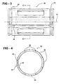
- Figure 3 is a side view of the sleeve of Figure 2 having grooves and a plurality of segments;
- Figure 4 is a front view of the sleeve of Figure 2 ;
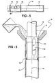
- Figure 5 is a side view of the sleeve of Figure 1 mounted to the inner jacket with a fastener before being inserted into the outer jacket;
- Figure 6 is a partial cross-sectional side view of the steering column assembly with a liquid thermosetting composition being poured between the sleeve and the outer jacket of Figure 1 through an opening defined by the outer jacket;
- Figure 7 is a partial cross-sectional side view of the steering column assembly with the liquid thermosetting composition being injected between the sleeve and the outer jacket of Figure 1 through a hole defined by the outer jacket.
- a steering column assembly 10 is shown generally at numeral 10.
- the steering column assembly 10 includes an outer jacket 12 extending along a longitudinal axis 14.
- the outer jacket 12 is used to mount the steering column assembly 10 to a vehicle.
- the outer jacket 12 typically has a tube-shaped configuration and may have a cylindrical cross-section, a rectangular cross-section, or any other cross-section known in the art to define an opening 16.
- the opening 16 is defined in the outer jacket 12 along the longitudinal axis 14.
- An inner jacket 18 is slideably disposed in the outer jacket 12 and is typically used to support the steering wheel in the outer jacket 12.
- the inner jacket 18 typically has a tube-shaped configuration and may have a cylindrical cross-section, a rectangular cross-section, or any other cross-section known in the art that may fit inside the outer jacket 12.
- the inner jacket 18 has the same cross-sectional shape as the outer jacket 12.
- the inner jacket 18 is disposed in the opening 16 of the outer jacket 12, which allows the inner jacket 18 to be coaxially aligned with the outer jacket 12 along the longitudinal axis 14 such that the inner jacket 18 is able to move telescopically relative to the outer jacket 12 along the longitudinal axis 14.
- the inner jacket 18 When disposed in the opening 16 and during telescoping movement, the inner jacket 18 is spaced from the outer jacket 12. In other words, the portion of the inner jacket 18 that is disposed within the outer jacket 12 is not in direct contact with the outer jacket 12. It is to be appreciated that other portions of the inner jacket 18 may be in direct contact with the outer jacket 12 at various times during telescoping movement.
- a sleeve 20 is disposed between the inner and outer jackets 12, 18 along the longitudinal axis 14.
- the sleeve 20 is mounted to the outer jacket 12 so that the sleeve 20 does not move along the longitudinal axis 14 during telescoping movement.
- the inner jacket 18 slides inside the sleeve 20 during telescoping movement.
- the sleeve 20 exerts a predetermined frictional force on the inner jacket 18, which opposes the telescoping movement of the inner jacket 18 relative to the outer jacket 12. This predetermined frictional force must be overcome in order for the inner jacket 18 to telescope relative to the outer jacket 12.
- the filler 22 is disposed between the sleeve 20 and the outer jacket 12.
- the filler 22 is shown partially in cross-section.
- the filler 22 is formed from a liquid thermosetting composition and is the reaction product of a resin and a cross-linking agent.
- the resin may be an epoxy and the cross-linking agent may be an anhydride.
- the liquid thermosetting composition is cured by adding the anhydride to the resin. Once cured, the liquid thermosetting composition becomes the filler 22. It is to be appreciated that the filler 22 is classified as a thermoset material, and therefore the filler 22 includes the physical and chemical properties associated with a thermoset material as is known in the art, as opposed to a thermoplastic material.
- the sleeve 20 defines at least one groove 24 and the filler 22 is disposed in the groove 24 between the sleeve 20 and the outer jacket 12.
- the sleeve 20 defines an outer perimeter 26 and the at least one groove 24 extends around the outer perimeter 26 of the sleeve 20.
- the at least one groove 24 extends completely around the sleeve 20.
- the filler 22 secures the sleeve 20 to the outer jacket 12 and maintains the predetermined frictional force exerted by the sleeve 20 on the inner jacket 18.
- the liquid thermosetting composition may be inserted into the groove 24 through a hole 28 defined by the outer jacket 12.
- the sleeve 20 may define an overflow gap 30 in communication with the groove 24.
- the overflow gap 30 extends transverse to the groove 24 and receives the liquid thermosetting composition when the groove 24 is filled. It is to be understood that the sleeve 20 may have a single groove 24, and the filler 22 is disposed in the groove 24 to secure the sleeve 20 to the outer jacket 12.
- the sleeve 20 may define a plurality of grooves 24, and the grooves 24 are spaced from one another around the outer perimeter 26 of the sleeve 20.
- the filler 22 is disposed in each groove 24 to secure the sleeve 20 to the outer jacket 12.
- the sleeve 20 may partially abut the outer jacket 12. It is to be understood that the sleeve 20 may have any number of grooves 24, and the filler 22 may be disposed in each of the grooves 24.
- the sleeve 20 has no grooves 24, and is spaced from the outer jacket 12 when disposed between the inner jacket 18 and the outer jacket 12.
- the filler 22 may fill in the entire space between the outer jacket 12 and the sleeve 20.
- a seal 32 such as an o-ring, may be disposed on the sleeve 20 to hold the filler 22 onto the sleeve 20.
- seals 32 may be used to hold the filler 22 onto the sleeve 20.
- This embodiment is preferred when the liquid thermosetting composition is poured between the outer jacket 12 and the sleeve 20 through the opening 16.
- the liquid thermosetting composition may be inserted between the outer jacket 12 and the sleeve 20 through the hole 28 as described in the previous embodiment.
- a guide 34 may be disposed about the sleeve 20 between the sleeve 20 and the outer jacket 12 instead of a single seal 32.
- the guide 34 is in communication with the hole 28 defined by the outer jacket 12.
- the guide 34 may include a pair of seals 32 disposed about the sleeve 20 and spaced from one another about the hole 28 to define a passage.
- the filler 22 is only disposed on the sleeve 20 in the space between the seals 32.
- the sleeve 20 may have a unitary configuration.
- the sleeve 20 may be formed from a sheet that is disposed around the inner jacket 18. The predetermined frictional force is dependent upon how tightly the sheet is wrapped around the inner jacket 18.
- the sleeve 20 may include a plurality of segments 36.
- the sleeve 20 may include the grooves 24 regardless of whether the sleeve 20 is formed from a sheet or has segments 36 connected by hinges 38.
- At least one hinge 38 is coupled between each of the segments 36 for adjusting the predetermined frictional force exerted on the inner jacket 18 opposing the telescoping movement.
- Each of the plurality of segments 36 has a cross-section to fit around the inner jacket 18. For instance, if the inner jacket 18 has a circular cross-section, then the segments 36 have a circular cross-section when coupled together. Therefore, each individual segment has a semi-circular cross-sectional configuration.
- the plurality of segments 36 may be tightened or loosened to adjust the predetermined frictional force exerted on the inner jacket 18 opposing the telescoping movement.
- the segments 36 may have any cross-section to fit between the inner jacket 18 and the outer jacket 12.
- the sleeve 20 may include a first segment 40 and a last segment 42 that overlaps the first segment 40.
- Each of the first and last segments 40, 42 may include recessed portions.
- the overflow gap 30 previously described may be defined by a space between the recessed portions of the first segment 40 and the last segment 42. In other words, the width of the overflow gap 30 may be dependent upon how tightly the sleeve 20 is disposed on the inner jacket 18.
- the sleeve 20 includes a fastener 44 for securing the sleeve 20 to the inner jacket 18 with the predetermined frictional force opposing the telescoping movement.
- the fastener 44 holds the sleeve 20 onto the inner jacket 18 until the filler 22 is disposed between the sleeve 20 and the outer jacket 12. Once the sleeve 20 is disposed on the inner jacket 18, it is tightened or loosened to exert the predetermined frictional force.
- the fastener 44 is a tape or a band that wraps around the fastener 44, although the fastener 44 may be any fastener known in the art to hold the sleeve 20 onto the inner jacket 18.
- the subject invention further discloses a method of forming the steering column assembly 10 to have telescoping movement.
- the method uses the outer jacket 12, the inner jacket 18, the sleeve 20, and the liquid thermosetting composition.
- the method includes disposing the inner jacket 18 into the outer jacket 12.
- Disposing the inner jacket 18 in the outer jacket 12 may be further defined as disposing the inner jacket 18 into the opening 16 of the outer jacket 12.
- the method includes disposing the sleeve 20 between the inner and outer jackets 12, 18 to exert the predetermined frictional force on the inner jacket 18 opposing the telescoping movement.
- disposing the inner jacket 18 into the outer jacket 12 may be simultaneous with disposing the sleeve 20 between the inner and outer jacket 12, 18 since disposing the sleeve 20 onto the inner jacket 18 may be before the step of disposing the sleeve 20 between the inner and outer jacket 12, 18.
- disposing the sleeve 20 on the inner jacket 18 may be further defined as wrapping the sleeve 20 around the inner jacket 18 before disposing the inner jacket 18 into the outer jacket 12.
- the method includes inserting the liquid thermosetting composition into the outer jacket 12 between the outer jacket 12 and the sleeve 20.
- the method also includes curing the liquid thermosetting composition to form the filler 22 and secure the sleeve 20 to the outer jacket 12 to maintain the predetermined frictional force opposing the telescoping movement.
- Inserting the liquid thermosetting composition may be further defined as inserting the resin, and curing the liquid thermosetting composition may be further defined as inserting the cross-linking agent after the step of inserting the resin.
- inserting the resin may be simultaneous with inserting the cross-linking agent. Inserting the resin simultaneously with the cross-linking agent may include mixing the resin with the cross-linking agent before inserting the liquid thermosetting composition.
- the resin and the cross-linking agent may be inserted into the outer jacket 12 simultaneously and mix inside the outer jacket 12.
- the outer jacket 12 defines the opening 16. Therefore, as shown in Figure 6 , inserting the liquid thermosetting composition is further defined as pouring the liquid thermosetting composition into the opening 16 before curing the liquid thermosetting composition.
- the outer jacket 12 defines the hole 28. Therefore, as shown in Figure 7 , inserting the liquid thermosetting composition may be further defined as injecting the liquid thermosetting composition into the hole 28 before curing the liquid thermosetting composition.
- the guide 34 may be disposed about the sleeve 20, and in this case, the method includes the step of inserting the guide 34 into the outer jacket 12 between the outer jacket 12 and the sleeve 20 to define a passage and to route the liquid thermosetting composition into the passage.
Landscapes
- Engineering & Computer Science (AREA)
- Mechanical Engineering (AREA)
- General Engineering & Computer Science (AREA)
- Chemical & Material Sciences (AREA)
- Combustion & Propulsion (AREA)
- Transportation (AREA)
- Ocean & Marine Engineering (AREA)
- Steering Controls (AREA)
- Injection Moulding Of Plastics Or The Like (AREA)
Abstract
Description
- The present invention generally relates to a steering column assembly.
- Various steering column assemblies providing telescoping movement are known in the art. Generally, the telescoping steering column assemblies of the prior art include an outer jacket and an inner jacket slideably disposed in the outer jacket. A bushing is disposed inside the outer jacket and the inner jacket slides into the bushing. The bushing provides a frictional force that opposes telescoping movement and that frictional force must be overcome before the steering column may telescope. For the bushing to exert the frictional force, molten plastic is injected into an injection hole defined by the outer jacket at a high pressure. The injection pressure forces the bushing to conform to the shape of the inner jacket, which causes the frictional force to be exerted on the inner jacket. Typically, the frictional force is overcome by either a user pulling or pushing on the steering column or by the steering column telescoping electronically. One such telescoping steering column assembly is shown in
U.S. Patent No. 5,722,300 to Burkhard et al . (the '300 patent). The '300 patent discloses the bushing disposed in the outer jacket, and the inner jacket is disposed in the bushing. Once inserted, molten plastic is injected into the outer jacket to compress the bushing around the inner jacket. - Although telescoping steering column assemblies of the prior art are enjoyed by a wide variety of consumers, the injection pressure of the molten plastic can be difficult to control. Since the frictional force is a function of the injection pressure, the frictional force is difficult to predict and is inconsistent between steering column assemblies. Therefore, a steering column assembly is needed that provides a more consistent frictional force on the inner jacket opposing telescoping movement. Also, a steering column assembly is needed that provides a stronger bond than the molten plastic materials used in the steering column assemblies of the prior art.
- The subject invention provides a steering column assembly having an outer jacket extending along a longitudinal axis. An inner jacket is slideably disposed in the outer jacket for telescoping movement relative to the outer jacket along the longitudinal axis. A sleeve is disposed between the inner and outer jackets along the longitudinal axis for exerting a predetermined frictional force on the inner jacket opposing the telescoping movement. A filler is formed from a liquid thermosetting composition disposed between the sleeve and the outer jacket for securing the sleeve to the outer jacket and for maintaining the predetermined frictional force exerted by the sleeve on the inner jacket.
- The subject invention further provides a method of forming the steering column assembly. The method includes the steps of disposing the inner jacket into the outer jacket and disposing the sleeve between the inner and outer jackets to exert the predetermined frictional force on the inner jacket opposing the telescoping movement. The method further includes the step of inserting the liquid thermosetting composition into the outer jacket between the outer jacket and the sleeve. In addition, the method includes a step of curing the liquid thermosetting composition to form the filler and secure the sleeve to the outer jacket to maintain the predetermined frictional force opposing the telescoping movement.
- The filler formed from the liquid thermosetting composition disposed between the sleeve and the outer jacket allows the sleeve to exert the predetermined frictional force on the inner jacket more consistently than molten plastic used with the steering column assemblies of the prior art. Also, forming the filler from the liquid thermosetting composition provides a stronger bond between the sleeve and the outer jacket than the molten plastic materials used with the prior art steering column assemblies.
- Other advantages of the present invention will be readily appreciated, as the same becomes better understood by reference to the following detailed description when considered in connection with the accompanying drawings wherein:
-
Figure 1 is a cross-sectional side view of a first embodiment of a steering column assembly having a sleeve disposed between an inner jacket and an outer jacket along a longitudinal axis; -
Figure 2 is a partial cross-sectional side view of an alternative embodiment of the sleeve disposed between the inner jacket and the outer jacket along the longitudinal axis; -
Figure 3 is a side view of the sleeve ofFigure 2 having grooves and a plurality of segments; -
Figure 4 is a front view of the sleeve ofFigure 2 ; -
Figure 5 is a side view of the sleeve ofFigure 1 mounted to the inner jacket with a fastener before being inserted into the outer jacket; -
Figure 6 is a partial cross-sectional side view of the steering column assembly with a liquid thermosetting composition being poured between the sleeve and the outer jacket ofFigure 1 through an opening defined by the outer jacket; and -
Figure 7 is a partial cross-sectional side view of the steering column assembly with the liquid thermosetting composition being injected between the sleeve and the outer jacket ofFigure 1 through a hole defined by the outer jacket. - Referring to the Figures, wherein like numerals indicate corresponding parts throughout the several views, a
steering column assembly 10 is shown generally atnumeral 10. As shown inFigure 1 , thesteering column assembly 10 includes anouter jacket 12 extending along alongitudinal axis 14. Typically, theouter jacket 12 is used to mount thesteering column assembly 10 to a vehicle. Theouter jacket 12 typically has a tube-shaped configuration and may have a cylindrical cross-section, a rectangular cross-section, or any other cross-section known in the art to define anopening 16. The opening 16 is defined in theouter jacket 12 along thelongitudinal axis 14. - An
inner jacket 18 is slideably disposed in theouter jacket 12 and is typically used to support the steering wheel in theouter jacket 12. Theinner jacket 18 typically has a tube-shaped configuration and may have a cylindrical cross-section, a rectangular cross-section, or any other cross-section known in the art that may fit inside theouter jacket 12. Typically, theinner jacket 18 has the same cross-sectional shape as theouter jacket 12. Theinner jacket 18 is disposed in theopening 16 of theouter jacket 12, which allows theinner jacket 18 to be coaxially aligned with theouter jacket 12 along thelongitudinal axis 14 such that theinner jacket 18 is able to move telescopically relative to theouter jacket 12 along thelongitudinal axis 14. When disposed in the opening 16 and during telescoping movement, theinner jacket 18 is spaced from theouter jacket 12. In other words, the portion of theinner jacket 18 that is disposed within theouter jacket 12 is not in direct contact with theouter jacket 12. It is to be appreciated that other portions of theinner jacket 18 may be in direct contact with theouter jacket 12 at various times during telescoping movement. - To separate the
inner jacket 18 from theouter jacket 12 during telescoping movement, asleeve 20 is disposed between the inner andouter jackets longitudinal axis 14. Thesleeve 20 is mounted to theouter jacket 12 so that thesleeve 20 does not move along thelongitudinal axis 14 during telescoping movement. However, theinner jacket 18 slides inside thesleeve 20 during telescoping movement. When disposed between theinner jacket 18 and theouter jacket 12, thesleeve 20 exerts a predetermined frictional force on theinner jacket 18, which opposes the telescoping movement of theinner jacket 18 relative to theouter jacket 12. This predetermined frictional force must be overcome in order for theinner jacket 18 to telescope relative to theouter jacket 12. - Referring now to
Figure 2 , when thesleeve 20 is mounted in theouter jacket 12, afiller 22 is disposed between thesleeve 20 and theouter jacket 12. Thefiller 22 is shown partially in cross-section. Thefiller 22 is formed from a liquid thermosetting composition and is the reaction product of a resin and a cross-linking agent. The resin may be an epoxy and the cross-linking agent may be an anhydride. Those skilled in the art realize that other resins and cross-linking agents may be used within the scope of the invention. The liquid thermosetting composition is cured by adding the anhydride to the resin. Once cured, the liquid thermosetting composition becomes thefiller 22. It is to be appreciated that thefiller 22 is classified as a thermoset material, and therefore thefiller 22 includes the physical and chemical properties associated with a thermoset material as is known in the art, as opposed to a thermoplastic material. - As shown in
Figures 2-4 , in one embodiment, thesleeve 20 defines at least onegroove 24 and thefiller 22 is disposed in thegroove 24 between thesleeve 20 and theouter jacket 12. In this embodiment, thesleeve 20 defines an outer perimeter 26 and the at least onegroove 24 extends around the outer perimeter 26 of thesleeve 20. In other words, the at least onegroove 24 extends completely around thesleeve 20. Thefiller 22 secures thesleeve 20 to theouter jacket 12 and maintains the predetermined frictional force exerted by thesleeve 20 on theinner jacket 18. As shown inFigure 7 , the liquid thermosetting composition may be inserted into thegroove 24 through ahole 28 defined by theouter jacket 12. When theinner jacket 18 andsleeve 20 are mounted to theouter jacket 12, thehole 28 is aligned with thegroove 24 and is in communication with thegroove 24, which allows the liquid thermosetting composition to travel through thehole 28 and into thegroove 24. Referring back toFigures 2-4 , to prevent an overflow of the liquid thermosetting liquid, thesleeve 20 may define anoverflow gap 30 in communication with thegroove 24. Theoverflow gap 30 extends transverse to thegroove 24 and receives the liquid thermosetting composition when thegroove 24 is filled. It is to be understood that thesleeve 20 may have asingle groove 24, and thefiller 22 is disposed in thegroove 24 to secure thesleeve 20 to theouter jacket 12. Alternatively, thesleeve 20 may define a plurality ofgrooves 24, and thegrooves 24 are spaced from one another around the outer perimeter 26 of thesleeve 20. Thefiller 22 is disposed in eachgroove 24 to secure thesleeve 20 to theouter jacket 12. In either of these alternatives, thesleeve 20 may partially abut theouter jacket 12. It is to be understood that thesleeve 20 may have any number ofgrooves 24, and thefiller 22 may be disposed in each of thegrooves 24. - As shown in
Figure 6 , in another embodiment, instead of the at least onegroove 24, thesleeve 20 has nogrooves 24, and is spaced from theouter jacket 12 when disposed between theinner jacket 18 and theouter jacket 12. Instead of filling in thegroove 24, thefiller 22 may fill in the entire space between theouter jacket 12 and thesleeve 20. Aseal 32, such as an o-ring, may be disposed on thesleeve 20 to hold thefiller 22 onto thesleeve 20. Those skilled in the art realize thatother seals 32 may be used to hold thefiller 22 onto thesleeve 20. This embodiment is preferred when the liquid thermosetting composition is poured between theouter jacket 12 and thesleeve 20 through theopening 16. However, the liquid thermosetting composition may be inserted between theouter jacket 12 and thesleeve 20 through thehole 28 as described in the previous embodiment. When inserted through thehole 28, aguide 34 may be disposed about thesleeve 20 between thesleeve 20 and theouter jacket 12 instead of asingle seal 32. Theguide 34 is in communication with thehole 28 defined by theouter jacket 12. Theguide 34 may include a pair ofseals 32 disposed about thesleeve 20 and spaced from one another about thehole 28 to define a passage. In this embodiment, thefiller 22 is only disposed on thesleeve 20 in the space between theseals 32. - Regardless of whether the
sleeve 20 includesgrooves 24 or is formed withoutgrooves 24, various types ofsleeves 20 may be used in accordance with the subject invention. For instance, thesleeve 20 may have a unitary configuration. In other words, thesleeve 20 may be formed from a sheet that is disposed around theinner jacket 18. The predetermined frictional force is dependent upon how tightly the sheet is wrapped around theinner jacket 18. As shown inFigures 3 and 4 , in another embodiment, thesleeve 20 may include a plurality ofsegments 36. Thesleeve 20 may include thegrooves 24 regardless of whether thesleeve 20 is formed from a sheet or hassegments 36 connected by hinges 38. In the embodiment having thesegments 36, at least onehinge 38 is coupled between each of thesegments 36 for adjusting the predetermined frictional force exerted on theinner jacket 18 opposing the telescoping movement. Each of the plurality ofsegments 36 has a cross-section to fit around theinner jacket 18. For instance, if theinner jacket 18 has a circular cross-section, then thesegments 36 have a circular cross-section when coupled together. Therefore, each individual segment has a semi-circular cross-sectional configuration. The plurality ofsegments 36 may be tightened or loosened to adjust the predetermined frictional force exerted on theinner jacket 18 opposing the telescoping movement. Those skilled in the art realize that thesegments 36 may have any cross-section to fit between theinner jacket 18 and theouter jacket 12. Also, thesleeve 20 may include afirst segment 40 and alast segment 42 that overlaps thefirst segment 40. Each of the first andlast segments overflow gap 30 previously described may be defined by a space between the recessed portions of thefirst segment 40 and thelast segment 42. In other words, the width of theoverflow gap 30 may be dependent upon how tightly thesleeve 20 is disposed on theinner jacket 18. - Referring now to
Figure 5 , in either of the embodiments described above, thesleeve 20 includes afastener 44 for securing thesleeve 20 to theinner jacket 18 with the predetermined frictional force opposing the telescoping movement. In other words, thefastener 44 holds thesleeve 20 onto theinner jacket 18 until thefiller 22 is disposed between thesleeve 20 and theouter jacket 12. Once thesleeve 20 is disposed on theinner jacket 18, it is tightened or loosened to exert the predetermined frictional force. Then, thesleeve 20 is held in place with thefastener 44 to exert the predetermined frictional force on theinner jacket 18 until thefiller 22 is disposed between thesleeve 20 and theouter jacket 12 to hold thesleeve 20 in place with the predetermined frictional force. Preferably, thefastener 44 is a tape or a band that wraps around thefastener 44, although thefastener 44 may be any fastener known in the art to hold thesleeve 20 onto theinner jacket 18. - The subject invention further discloses a method of forming the
steering column assembly 10 to have telescoping movement. The method uses theouter jacket 12, theinner jacket 18, thesleeve 20, and the liquid thermosetting composition. The method includes disposing theinner jacket 18 into theouter jacket 12. Disposing theinner jacket 18 in theouter jacket 12 may be further defined as disposing theinner jacket 18 into theopening 16 of theouter jacket 12. Next, the method includes disposing thesleeve 20 between the inner andouter jackets inner jacket 18 opposing the telescoping movement. In the method, disposing theinner jacket 18 into theouter jacket 12 may be simultaneous with disposing thesleeve 20 between the inner andouter jacket sleeve 20 onto theinner jacket 18 may be before the step of disposing thesleeve 20 between the inner andouter jacket sleeve 20 on theinner jacket 18 may be further defined as wrapping thesleeve 20 around theinner jacket 18 before disposing theinner jacket 18 into theouter jacket 12. - Next, the method includes inserting the liquid thermosetting composition into the
outer jacket 12 between theouter jacket 12 and thesleeve 20. The method also includes curing the liquid thermosetting composition to form thefiller 22 and secure thesleeve 20 to theouter jacket 12 to maintain the predetermined frictional force opposing the telescoping movement. Inserting the liquid thermosetting composition may be further defined as inserting the resin, and curing the liquid thermosetting composition may be further defined as inserting the cross-linking agent after the step of inserting the resin. Alternatively, inserting the resin may be simultaneous with inserting the cross-linking agent. Inserting the resin simultaneously with the cross-linking agent may include mixing the resin with the cross-linking agent before inserting the liquid thermosetting composition. On the other hand, the resin and the cross-linking agent may be inserted into theouter jacket 12 simultaneously and mix inside theouter jacket 12. - As described above, the
outer jacket 12 defines theopening 16. Therefore, as shown inFigure 6 , inserting the liquid thermosetting composition is further defined as pouring the liquid thermosetting composition into theopening 16 before curing the liquid thermosetting composition. Alternatively, as described above, theouter jacket 12 defines thehole 28. Therefore, as shown inFigure 7 , inserting the liquid thermosetting composition may be further defined as injecting the liquid thermosetting composition into thehole 28 before curing the liquid thermosetting composition. Here, theguide 34 may be disposed about thesleeve 20, and in this case, the method includes the step of inserting theguide 34 into theouter jacket 12 between theouter jacket 12 and thesleeve 20 to define a passage and to route the liquid thermosetting composition into the passage. - The invention has been described in an illustrative manner, and it is to be understood that the terminology which has been used is intended to be in the nature of words of description rather than of limitation. As is now apparent to those skilled in the art, many modifications and variations of the present invention are possible in light of the above teachings. It is, therefore, to be understood that within the scope of the appended claims the invention may be practiced otherwise than as specifically described.
Claims (20)
- A steering column assembly comprising:an outer jacket extending along a longitudinal axis;an inner jacket slideably disposed in said outer jacket for telescoping movement relative to said outer jacket along said longitudinal axis;a sleeve disposed between said inner and outer jackets along said longitudinal axis for exerting a predetermined frictional force on said inner jacket opposing the telescoping movement; anda filler formed from a liquid thermosetting composition disposed between said sleeve and said outer jacket for securing said sleeve to said outer jacket and for maintaining the predetermined frictional force exerted by said sleeve on said inner jacket.
- A steering column assembly as set forth in claim 1 wherein said filler comprises the reaction product of a resin and a cross-linking agent.
- A steering column assembly as set forth in claim 2 wherein said resin is further defined as an epoxy and said cross-linking agent is further defined as an anhydride.
- A method of forming a steering column assembly having telescoping movement and using an outer jacket, an inner jacket, a sleeve, and a liquid thermosetting composition, said method comprising the steps of:disposing the inner jacket into the outer jacket;disposing the sleeve between the inner and outer jackets to exert a predetermined frictional force on the inner jacket opposing the telescoping movement;inserting the liquid thermosetting composition into the outer jacket between the outer jacket and the sleeve; andcuring the liquid thermosetting composition to form a filler and secure the sleeve to the outer jacket to maintain the predetermined frictional force opposing the telescoping movement.
- A method as set forth in claim 4 wherein the outer jacket defines an opening and wherein inserting the liquid thermosetting composition is further defined as pouring the liquid thermosetting composition into the opening before curing the liquid thermosetting composition.
- A method as set forth in claim 4 wherein the outer jacket defines a hole and wherein inserting the liquid thermosetting composition is further defined as injecting the liquid thermosetting composition into the hole before curing the liquid thermosetting composition.
- A method as set forth in claim 4 wherein the steering column assembly includes at least one guide and further including the step of inserting the guide into the outer jacket between the outer jacket and the sleeve to define a passage and to route the liquid thermosetting composition into the passage.
- A method as set forth in claim 4 wherein disposing the inner jacket into the outer jacket is simultaneous with disposing the sleeve between the inner and outer jackets.
- A method as set forth in claim 4 further including the step of disposing the sleeve onto the inner jacket before disposing the sleeve between the inner and outer jackets.
- A method as set forth in claim 9 wherein disposing the sleeve on the inner jacket is further defined as wrapping the sleeve around the inner jacket.
- A method as set forth in claim 4 wherein the liquid thermosetting composition comprises a resin and wherein inserting the liquid thermosetting composition is further defined as inserting the resin.
- A method as set forth in claim 11 wherein the liquid thermosetting composition further comprises a cross-linking agent and wherein curing the liquid thermosetting composition is further defined as inserting the cross-linking agent after the step of inserting the resin.
- A method as set forth in claim 4 wherein the liquid thermosetting composition comprises a resin and a cross-linking agent and further including mixing the resin with the cross-linking agent before inserting the liquid thermosetting composition.
- A steering column assembly comprising:an outer jacket extending along a longitudinal axis;an inner jacket slideably disposed in said outer jacket for telescoping movement relative to said outer jacket along said longitudinal axis;a sleeve disposed between said inner and outer jackets along said longitudinal axis for exerting a predetermined frictional force on said inner jacket opposing the telescoping movement and said sleeve defining at least one groove; anda filler disposed in said at least one groove between said sleeve and said outer jacket for securing said sleeve to said outer jacket and for maintaining the predetermined frictional force exerted by said sleeve on said inner jacket.
- A steering column assembly as set forth in claim 14 wherein said sleeve defines an outer perimeter and said at least one groove extends around said outer perimeter of said sleeve.
- A steering column assembly as set forth in claim 14 wherein said sleeve defines an outer perimeter and wherein said at least one groove is further defined as a plurality of grooves spaced from one another around said outer perimeter of said sleeve.
- A steering column assembly as set forth in claim 14 wherein said outer jacket defines a hole aligned with said grove and in communication with said groove.
- A steering column assembly as set forth in claim 14 wherein said sleeve defines an overflow gap in communication with said at least one groove.
- A steering column assembly as set forth in claim 14 wherein said sleeve has a unitary configuration.
- A steering column assembly as set forth in claim 14 wherein said sleeve includes a plurality of segments and at least one hinge coupled between each of said segments for adjusting the predetermined frictional force exerted on said inner jacket opposing the telescoping movement.
Applications Claiming Priority (1)
| Application Number | Priority Date | Filing Date | Title |
|---|---|---|---|
| US11/726,210 US8092635B2 (en) | 2007-03-21 | 2007-03-21 | Adjustable steering column utilizing a sleeve and a method of forming a filler with a sleeve |
Publications (2)
| Publication Number | Publication Date |
|---|---|
| EP1972523A2 true EP1972523A2 (en) | 2008-09-24 |
| EP1972523A3 EP1972523A3 (en) | 2011-05-04 |
Family
ID=39480216
Family Applications (1)
| Application Number | Title | Priority Date | Filing Date |
|---|---|---|---|
| EP08152375A Withdrawn EP1972523A3 (en) | 2007-03-21 | 2008-03-06 | Adjustable steering column utilizing a sleeve and a method of forming a filler with a sleeve |
Country Status (3)
| Country | Link |
|---|---|
| US (2) | US8092635B2 (en) |
| EP (1) | EP1972523A3 (en) |
| CN (2) | CN201553191U (en) |
Families Citing this family (7)
| Publication number | Priority date | Publication date | Assignee | Title |
|---|---|---|---|---|
| DE102009055025A1 (en) | 2008-12-19 | 2010-11-18 | C. Rob. Hammerstein Gmbh & Co. Kg | Axially adjustable steering column for vehicle has overlapping upper and lower sections with adjusting drive |
| DE112009002485A5 (en) | 2008-12-19 | 2012-07-05 | C. Rob. Hammerstein Gmbh & Co. Kg | Length-adjustable steering control unit for a motor vehicle with a carrier and with a steering column |
| CN102233897A (en) | 2010-04-23 | 2011-11-09 | C.劳勃.汉默斯坦两合有限公司 | Length adjustable steering column module for a motor vehicle |
| CN102167073A (en) * | 2011-03-15 | 2011-08-31 | 四川绵阳三力股份有限公司 | Steering column and sliding retention sleeve thereof |
| US8915521B2 (en) | 2013-03-15 | 2014-12-23 | Steering Solutions Ip Holding Corporation | Steering column telescoping bushing with roller springs |
| DE102013018149A1 (en) * | 2013-12-04 | 2015-06-11 | Daimler Ag | Steering column assembly A jacket tube for a steering column assembly, and vehicle having a steering column assembly |
| US10882164B2 (en) | 2016-02-24 | 2021-01-05 | Rohde & Schwarz Gmbh & Co. Kg | Hand tool with adjustable fastening head and variable output torque |
Citations (3)
| Publication number | Priority date | Publication date | Assignee | Title |
|---|---|---|---|---|
| US20020121014A1 (en) | 1998-09-23 | 2002-09-05 | Nsk Steering System Europe Limited | Method of constructing length-adjustable vehicle steering column assembly |
| DE10343685A1 (en) | 2003-09-20 | 2005-04-21 | Daimler Chrysler Ag | Vehicle steering column assembly |
| EP1669272A2 (en) | 2004-12-08 | 2006-06-14 | Delphi Technologies, Inc. | Internally injected telescope bushing |
Family Cites Families (31)
| Publication number | Priority date | Publication date | Assignee | Title |
|---|---|---|---|---|
| CA432226A (en) * | 1942-12-02 | 1946-01-01 | Henderson James | Laminated article manufacture |
| US2753799A (en) * | 1952-12-19 | 1956-07-10 | Vandercook & Sons Inc | Printing device |
| US3662515A (en) * | 1970-05-13 | 1972-05-16 | Robert O Stuberg | Process for sealing a top-opening carton |
| US3914116A (en) * | 1972-01-21 | 1975-10-21 | American Air Filter Co | High efficiency unit filter |
| US3799569A (en) | 1972-06-21 | 1974-03-26 | Case Co J I | Tilt and telescoping steering system |
| JPS49110032A (en) | 1973-02-22 | 1974-10-19 | ||
| US4058853A (en) * | 1975-09-29 | 1977-11-22 | Rubin Boxer | Socks with flexible self-contained fastener patches |
| US4397073A (en) * | 1979-05-18 | 1983-08-09 | The Continental Group, Inc. | Method for assembling container halves |
| US4369970A (en) * | 1979-07-10 | 1983-01-25 | Salminen Reijo K | Hockey stick and method of manufacturing the same |
| IL73328A (en) | 1984-10-26 | 1990-02-09 | Tzora Furniture Ind Ltd | Rotatable joint with coaxially assembled parts |
| FR2575137B3 (en) * | 1984-12-20 | 1987-11-27 | Sleever Int | HEAT SHRINKABLE COMPOSITE SHEATH AND MANUFACTURING METHOD THEREOF |
| GB2236168B (en) | 1989-09-21 | 1993-04-07 | Torrington Co | Vehicle steering column |
| US5243874A (en) * | 1992-02-24 | 1993-09-14 | Pittsburgh Tubular Shafting, Inc. | Method and apparatus for telescopically assembling a pair of elongated members |
| US5345679A (en) * | 1993-08-12 | 1994-09-13 | General Motors Corporation | Method of making plastic ball sleeve assembly |
| JP2935950B2 (en) | 1993-12-03 | 1999-08-16 | 株式会社山田製作所 | Steering shaft and apparatus for manufacturing the same |
| DE4440725C2 (en) * | 1994-11-15 | 1996-12-12 | Schaeffler Waelzlager Kg | Bearing arrangement for the play-free adjustment of a steering shaft in a steering column |
| FR2737173B1 (en) * | 1995-07-26 | 1997-10-10 | Nacam | DEPTH ADJUSTABLE STEERING COLUMN, WITH GUIDANCE DEVICE |
| US5833064A (en) * | 1996-05-17 | 1998-11-10 | Vertex Fasteners | String of anchor clips |
| JP3004590B2 (en) | 1996-08-02 | 2000-01-31 | 株式会社山田製作所 | Steering shaft |
| US5722300A (en) * | 1996-08-16 | 1998-03-03 | General Motors Corporation | Motor vehicle steering column |
| US6051449A (en) * | 1997-08-06 | 2000-04-18 | Micron Technology, Inc. | Method and apparatus for Epoxy loc die attachment |
| US5902186A (en) | 1997-08-08 | 1999-05-11 | Douglas Autotech Corp. | Intermediate shaft assembly for steering columns |
| US6473968B1 (en) | 1999-11-18 | 2002-11-05 | Ford Global Tech., Inc. | Telescoping joint assembly and a method for making the same |
| JP2004175298A (en) * | 2002-11-28 | 2004-06-24 | Koyo Seiko Co Ltd | Steering gear |
| US7784830B2 (en) * | 2003-10-23 | 2010-08-31 | Chrysler Group Llc | Axially adjustable steering column assembly with flexible bearing sleeve |
| GB0328695D0 (en) * | 2003-12-11 | 2004-01-14 | Trw Lucas Varity Electric | A steering column assembly |
| US20050200111A1 (en) | 2004-03-11 | 2005-09-15 | Cymbal William D. | Multi piece bearing for telescoping steering column assembly |
| US7516985B2 (en) | 2004-03-11 | 2009-04-14 | Delphi Technologies, Inc. | Multi piece bearing for telescoping steering column assembly |
| US7497470B2 (en) * | 2005-11-21 | 2009-03-03 | Delphi Technologies, Inc. | Energy absorbing apparatus |
| US8096036B2 (en) * | 2007-08-29 | 2012-01-17 | Nexteer (Beijing) Technology Co., Ltd. | Method of manufacturing a steering column |
| DE102007060149A1 (en) * | 2007-12-13 | 2009-06-18 | GM Global Technology Operations, Inc., Detroit | Telescopic steering spindle assembly |
-
2007
- 2007-03-21 US US11/726,210 patent/US8092635B2/en not_active Expired - Fee Related
-
2008
- 2008-03-06 EP EP08152375A patent/EP1972523A3/en not_active Withdrawn
- 2008-03-21 CN CN2009201667977U patent/CN201553191U/en not_active Expired - Fee Related
- 2008-03-21 CN CNU2008200084789U patent/CN201325477Y/en not_active Expired - Fee Related
-
2011
- 2011-11-29 US US13/306,425 patent/US8448987B2/en not_active Expired - Fee Related
Patent Citations (3)
| Publication number | Priority date | Publication date | Assignee | Title |
|---|---|---|---|---|
| US20020121014A1 (en) | 1998-09-23 | 2002-09-05 | Nsk Steering System Europe Limited | Method of constructing length-adjustable vehicle steering column assembly |
| DE10343685A1 (en) | 2003-09-20 | 2005-04-21 | Daimler Chrysler Ag | Vehicle steering column assembly |
| EP1669272A2 (en) | 2004-12-08 | 2006-06-14 | Delphi Technologies, Inc. | Internally injected telescope bushing |
Also Published As
| Publication number | Publication date |
|---|---|
| US8448987B2 (en) | 2013-05-28 |
| CN201325477Y (en) | 2009-10-14 |
| US8092635B2 (en) | 2012-01-10 |
| EP1972523A3 (en) | 2011-05-04 |
| US20080229866A1 (en) | 2008-09-25 |
| CN201553191U (en) | 2010-08-18 |
| US20120067159A1 (en) | 2012-03-22 |
Similar Documents
| Publication | Publication Date | Title |
|---|---|---|
| US8448987B2 (en) | Adjustable steering column utilizing a sleeve and a method of forming a filler with a sleeve | |
| JP2935950B2 (en) | Steering shaft and apparatus for manufacturing the same | |
| DE69400847T2 (en) | System and method for sealing a wire harness against water | |
| US6010134A (en) | Sealed grommet for wire harnesses having a split cylindrical core member with a complementary grommet sleeve | |
| EP1635423B1 (en) | Method for waterproofing a terminal splice | |
| EP3250440B1 (en) | Apparatus for introducing an auxiliary torque into a steering shaft of an electromechanical power steering system | |
| US20170129545A1 (en) | Frame structure with at least one console for connecting further components, method for producing and motor vehicle body | |
| US20160190782A1 (en) | Electric Wire Protective Member | |
| DE69407237T2 (en) | Method for producing a rotation sensor and construction of a rotation sensor | |
| US7708500B2 (en) | Resin anchor with a compressible envelope containing a curable product | |
| GB2082113A (en) | Method of producing a length of flexible tubing in the form of a toothed belt | |
| US20150145189A1 (en) | Shock-absorber and method for manufacturing a shock-absorber | |
| EP1669272B1 (en) | Internally injected telescope bushing | |
| EP4389574A1 (en) | Method for producing a steering arrangement | |
| EP2897778B1 (en) | Method for producing a cable harness and cable harness | |
| DE10054714A1 (en) | Sealing cable into/onto cable leadthrough channel involves spraying an especially elastomeric sealing element, applying mold, injecting hollow volume with harder plastic material | |
| DE1920637A1 (en) | Telephone cable joint with plastic foam - filled sleeve | |
| JP4924388B2 (en) | Grommet waterproof method and waterproof structure | |
| DE102006049689B3 (en) | Wiring harnesses longitudinal water sealing method for motor vehicle, involves setting position in which diameter of lower tubular section corresponding to upper section, where diameter is set by hardened compound within upper section | |
| KR950018958A (en) | Ground Anchor Method | |
| JPH02206518A (en) | Molding of plastic molded product | |
| KR101983874B1 (en) | The anti. noise member filling method of dust cover for vehicle steering equipment | |
| EP2287986B1 (en) | Filler assembly for cable gland | |
| EP2958409B1 (en) | Electric distributor and a plastic injection moulding method for its production | |
| EP1738987B1 (en) | Telescoping steering column assembly and method of manufacturing the assembly |
Legal Events
| Date | Code | Title | Description |
|---|---|---|---|
| PUAI | Public reference made under article 153(3) epc to a published international application that has entered the european phase |
Free format text: ORIGINAL CODE: 0009012 |
|
| AK | Designated contracting states |
Kind code of ref document: A2 Designated state(s): AT BE BG CH CY CZ DE DK EE ES FI FR GB GR HR HU IE IS IT LI LT LU LV MC MT NL NO PL PT RO SE SI SK TR |
|
| AX | Request for extension of the european patent |
Extension state: AL BA MK RS |
|
| RAP1 | Party data changed (applicant data changed or rights of an application transferred) |
Owner name: GM GLOBAL TECHNOLOGY OPERATIONS, INC. |
|
| PUAL | Search report despatched |
Free format text: ORIGINAL CODE: 0009013 |
|
| AK | Designated contracting states |
Kind code of ref document: A3 Designated state(s): AT BE BG CH CY CZ DE DK EE ES FI FR GB GR HR HU IE IS IT LI LT LU LV MC MT NL NO PL PT RO SE SI SK TR |
|
| AX | Request for extension of the european patent |
Extension state: AL BA MK RS |
|
| RAP1 | Party data changed (applicant data changed or rights of an application transferred) |
Owner name: GM GLOBAL TECHNOLOGY OPERATIONS LLC |
|
| 17P | Request for examination filed |
Effective date: 20111102 |
|
| AKX | Designation fees paid |
Designated state(s): DE |
|
| RAP1 | Party data changed (applicant data changed or rights of an application transferred) |
Owner name: GM GLOBAL TECHNOLOGY OPERATIONS LLC Owner name: STEERING SOLUTIONS IP HOLDING CORPORATION |
|
| 17Q | First examination report despatched |
Effective date: 20121205 |
|
| STAA | Information on the status of an ep patent application or granted ep patent |
Free format text: STATUS: THE APPLICATION IS DEEMED TO BE WITHDRAWN |
|
| 18D | Application deemed to be withdrawn |
Effective date: 20130618 |