EP1972498A2 - Interchangeable module for an object-holding drawer of a dashboard of a motor vehicle and object-holding drawer fitted with such interchangeable module - Google Patents
Interchangeable module for an object-holding drawer of a dashboard of a motor vehicle and object-holding drawer fitted with such interchangeable module Download PDFInfo
- Publication number
- EP1972498A2 EP1972498A2 EP08153161A EP08153161A EP1972498A2 EP 1972498 A2 EP1972498 A2 EP 1972498A2 EP 08153161 A EP08153161 A EP 08153161A EP 08153161 A EP08153161 A EP 08153161A EP 1972498 A2 EP1972498 A2 EP 1972498A2
- Authority
- EP
- European Patent Office
- Prior art keywords
- container
- module
- module according
- shell
- drawer
- Prior art date
- Legal status (The legal status is an assumption and is not a legal conclusion. Google has not performed a legal analysis and makes no representation as to the accuracy of the status listed.)
- Granted
Links
- 238000000605 extraction Methods 0.000 claims description 5
- 238000002360 preparation method Methods 0.000 claims description 3
- 238000005057 refrigeration Methods 0.000 claims description 3
- 239000000463 material Substances 0.000 claims description 2
- 239000002184 metal Substances 0.000 claims description 2
- 239000004033 plastic Substances 0.000 claims description 2
- 239000000470 constituent Substances 0.000 description 2
- 244000201986 Cassia tora Species 0.000 description 1
- 238000004378 air conditioning Methods 0.000 description 1
- 230000000694 effects Effects 0.000 description 1
- 239000011152 fibreglass Substances 0.000 description 1
- 238000004519 manufacturing process Methods 0.000 description 1
- 238000012986 modification Methods 0.000 description 1
- 230000004048 modification Effects 0.000 description 1
Images






Classifications
-
- B—PERFORMING OPERATIONS; TRANSPORTING
- B60—VEHICLES IN GENERAL
- B60R—VEHICLES, VEHICLE FITTINGS, OR VEHICLE PARTS, NOT OTHERWISE PROVIDED FOR
- B60R7/00—Stowing or holding appliances inside vehicle primarily intended for personal property smaller than suit-cases, e.g. travelling articles, or maps
- B60R7/04—Stowing or holding appliances inside vehicle primarily intended for personal property smaller than suit-cases, e.g. travelling articles, or maps in driver or passenger space, e.g. using racks
- B60R7/06—Stowing or holding appliances inside vehicle primarily intended for personal property smaller than suit-cases, e.g. travelling articles, or maps in driver or passenger space, e.g. using racks mounted on or below dashboards
Definitions
- This invention relates to an interchangeable module for an object-holding drawer of a dashboard of a motor vehicle.
- the aim of the present invention is to meet the above-mentioned requirements in a simple and economical manner.
- a module is made for an object-holding drawer of a dashboard of a motor-vehicle; it being possible to choose the module from among a plurality of various modules to accommodate different objects, and comprising:
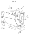
- FIG. 1 shows an object-holding drawer forming part of a dashboard of a motor vehicle (not shown) and comprising a shell 3 connected in a fixed position in a manner not illustrated to a cross-member 4 that supports the dashboard.
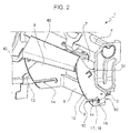
- the shell 3 is made of a plastic material, reinforced preferably with fibreglass, and comprises a back wall 6, an upper wall 7 and two side walls 8.
- a metal bracket 10 is arranged along the outer surface of the walls 8 and 6 and is fixed to the cross-member 4 both to stiffen the shell 3 and/or the connection of the shell 3 to the cross-member 4, and to support an interchangeable module, as will be better explained below.
- the walls 8 comprise respective edges 12 facing the passenger compartment and defining the sides of an opening 13 to access the space inside the shell 3.
- the walls 8 have two slots 14, which extend from the edges 12 and are parallel to each other and comprise respective initial straight sections 16 that are substantially horizontal and respective blind end sections 17.
- the sections 17 are facing downwards in relation to the sections 16 and define respective seats, which are aligned with respective retaining and supporting seats 18 made in the ends 19 of the bracket 10.
- the shell 3 houses a module 20, which entirely occupies the space between the walls 8 and comprises a container 21.
- the container 21 in turn comprises an upper wall 24, a back wall 25, and two side walls 26, which define an opening 27 towards the passenger compartment.
- the walls 26 are connected to the walls 8 and to the bracket 10 by means of a connecting device 30, which comprises two pins 31 ( Figure 6 ), which are coaxial with each other along a horizontal axis 32, overhang outwards in relation to the walls 26, terminate with respective flanges 33 of a larger diameter, engage in the seats 18 due to the effect of the weight of the module 20 and are therefore supported by the ends 19.
- the device 30 also comprises two resilient teeth 34 made in one piece with the walls 8, and two seats 35 made in the walls 26 and engaged by the teeth 34.
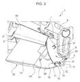
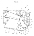
- the module 20 is fitted by inserting the container 20 into the shell 3 through the opening 13 and, at the same time, the pins 31 in the slots 14, with the flanges 33 arranged beyond the walls 8 and with the opening 27 facing downwards.
- the pins 31 are made to slide down to the bottom of the slots 14, that is until they rest against the ends 19 in the seats 18. In this way, the module 20 remains held longitudinally by the seats 18. The module 20 is then rotated upwards about the axis 32 elastically deforming the teeth 34 until the teeth 34 click into their respective seats 35 ( Figure 7 ).
- the module 20 is removed by means of a special tool (not shown), which is used from outside by inserting it between the walls 26 and 8, for example in appropriate grooves (not shown), until the teeth 34 are released from the seats 35.
- the wall 25 is drawn towards the wall 6; the opening 27 coincides with the bottom part of the opening 13; and the wall 24 defines, together with the walls 7 and 8, a compartment 38 accessible through an opening 39.
- the opening 39 coincides with the top part of the opening 13 and can be opened/closed by a door 40, which is hinged to the walls 8 in order to rotate about a horizontal axis 41 ( Figures 2-4 ).
- the module 20 also comprises a door 43 which is hinged to the walls 26 by means of the pins 31 to rotate about the axis 32 and open/close the opening 27. Therefore, the door 43 forms part of the module 20.
- a releasable holding device (not shown) is provided to hold the door 43 in the closed position.
- the module 20 comprises a bottom cradle 45 which is provided to stow objects, such as bottles 46, and is fixed in relation to the door 43 so as to pivot about the axis 32, and covers the entire internal surface of the door 43.
- the container 21 and the cradle 45 are thermally insulated and define a compartment 47, which can be cooled by means of a flow of air from the motor vehicle's air-conditioning system, or by means of a known refrigeration system (not shown), comprising a condenser, an evaporator, an engine-compressor and a thermostat that automatically regulates the temperature in the compartment 47 by switching the engine-compressor on and off.
- the refrigeration system is arranged in the compartment 38 and carried by the wall 24 (in this case, the door 40 could be in the form of a fixed panel).
- the door 43 has, in a fixed position, two side walls 50 which slide along the walls 26 during the opening/closing of the door 43.
- the pins 31 extend axially overhanging the walls 50, they are fixed in relation to the walls 50 and engage in a rotating manner respective hinge seats 51 made in the walls 26.
- the pins 31 are fixed in relation to the walls 26 and engage in a rotating manner respective hinge seats made in the walls 50.
- FIGS 9 and 10 illustrate a module 60, whose constituent parts are indicated, where possible, by the same reference numbers as module 20.
- the module 60 differs from the module 20 by the fact that the container 21 supports an electric machine 61 for the preparation of coffee (illustrated schematically), whose front surface is arranged in line with the opening 27.
- the machine 61 is fixed, in a manner not shown, to the container 21, it partially occupies the space between the walls 26 and has two drawers 62,63, which are arranged one above the other and can be extracted longitudinally.
- the drawer 62 is configured to insert a coffee pod, while the drawer 63 is configured to accommodate a beaker 64 into which the machine 61 causes the prepared coffee to pour.
- the door 43 has no cradle 45 but carries, in a fixed position, a plurality of object-holding compartments 65 (to hold the pods, beakers, sugar and stirrers or teaspoons) which lie alongside the machine 61 in the compartment 47 when the door 43 is in a closed position.
- FIGS 11 to 18 illustrate a module 70, whose constituent parts are shown, where possible, by the same reference numerals as modules 20 and 60.
- the module 70 comprises a frame 71 defining a compartment 72 inclined upwards; and a support 73, which can be extracted from the compartment 72 through the opening 39 and is configured to support a laptop computer 75.
- the frame 71 comprises a fin 76, which extends projecting upwards and in a position facing the door 43, it delimits the opening 27 with its upper edge, and defines a recess 77.
- the recess 77 is capable of housing objects such as notebooks, papers and pens and can be accessed by opening the door 43.
- the compartment 72 is delimited laterally by two walls 78, which form part of the frame 71 and are hinged to the door 43, in a way not shown, by means of the pins 31, and have projecting respective opposing attachment tabs 79 that snap lock onto the teeth 34 ( Figure 12 ).
- the walls 78 have respective pairs of guides 80 configured so as to cause the support 73 to slide outwards along an upwardly inclined straight section 81 and so as to rotate the support 73 towards a horizontal position along an extraction end section 82.
- the support 73 comprises a rectangular tray 83, on which to rest the laptop computer 75; a parallel rectangular plate 84 beneath the tray 83, and connected in a sliding manner to the guides 80; and a linkage 85 which connects the tray 83 to the plate 84 and comprises three connecting-pieces 88 all of the same length.
- the connecting-pieces 88 are connected in a rotating manner, at one of their ends 89, to the tray 83 and, at the opposite end 90, to the plate 84, so as substantially to define an articulated quadrilateral.
- the ends 90 engage in a sliding manner in respective straight guides 92 made in the plate 84 parallel to the short sides of the plate 84 and are joined together by a connecting-piece 94, which is arranged along the upper face of the plate 84 and keeps the ends 90 in positions that are aligned with each other while sliding/rotating in the guides 92.
- the ends 89 engage in a sliding manner in respective straight guides 95 made in the tray 83 parallel to a short side of the tray 83 and are joined together by means of a connecting-piece 97 ( Figures 13 and 14 ), which is arranged along the lower face of the tray 83 and keeps the ends 89 in positions that are aligned with each other while sliding/rotating in the guides 95.
- the tray 83 From this position, it is possible to slide the tray 83 sideways in relation to the plate 84 by rotating the connecting-pieces 88 in relation to the plate 84 about vertical axes defined by the ends 90 (in a clockwise direction in the Figure) and in relation to the tray 83 about respective vertical axes defined by the ends 89, but leaving the connecting-pieces 94 and 97 at right angles to the guides 92 and 95.
- the laptop computer can be used by a passenger sitting on a front middle seat of the motor vehicle.
- the laptop computer can be used by the driver sitting on the front left-hand seat of the motor vehicle.
- the module 70 is connected to the shell 3 in a similar manner to module 20: the door 40 is connected to the walls 8 subsequently to close the opening 39 located above the door 43.
- modules 20, 60 and 70 being mutually interchangeable, can be chosen as alternatives to each other, which means that they succeed in meeting the different requirements of users in an extremely simple manner and, therefore, result in versatile use of the drawer 1 by a user or in flexible outfitting of the motor vehicle during manufacture.
- pins 31 are used both to hinge the door 43 and to connect the module 20, 60, 70 to the shell 3 simplifies the constructional characteristics and fitting.
- Modules 20 and 60 are ideal for making the journey pleasant, while module 70 succeeds in transporting a laptop computer in a compact and efficient manner.
- top door 40 could form part of the interchangeable module and be hinged to the walls 26.
- the pins 31 could be carried by the walls 26 and 78, instead of by the door 43.
- the shell 3 need not have any bracket 10 if it were rigid enough to support the module 20, 60, 70 and the objects contained in the module on its own.
Landscapes
- Engineering & Computer Science (AREA)
- Mechanical Engineering (AREA)
- Vehicle Step Arrangements And Article Storage (AREA)
- Passenger Equipment (AREA)
- Fittings On The Vehicle Exterior For Carrying Loads, And Devices For Holding Or Mounting Articles (AREA)
Abstract
Description
- This invention relates to an interchangeable module for an object-holding drawer of a dashboard of a motor vehicle.
- There is a need for an object-holding drawer which is versatile and can be set up to suit the various requirements of drivers, which is spacious, has a relatively small number of components and is easy to use.
- The aim of the present invention is to meet the above-mentioned requirements in a simple and economical manner.
- According to the present invention a module is made for an object-holding drawer of a dashboard of a motor-vehicle; it being possible to choose the module from among a plurality of various modules to accommodate different objects, and comprising:
- a container defining an access opening;
- attachment means to connect the said container in a fixed position and in an interchangeable manner to a shell;
- a door to open and close the said access opening;
- two hinge elements coaxial with each other along a horizontal axis to hinge the said door to the said container about the said horizontal axis.
- The invention will now be described with reference to the accompanying drawings which illustrate a nonlimiting embodiment thereof, in which:
-
Figure 1 is a perspective view of an object-holding drawer for a dashboard of a motor vehicle provided with a first preferred embodiment of the interchangeable module according to the present invention; -
Figure 2 is similar toFigure 1 and illustrates the object-holding drawer without the interchangeable module; -
Figures 3 to 5 are similar toFigure 1 and show successive stages of fitting the interchangeable module; -
Figure 6 is a schematic section of the object-holding drawer along a transverse vertical plane indicated by Line VI-VI inFigure 1 and shows a detail of the connection of the interchangeable module; -
Figure 7 is a schematic section, on an enlarged scale, of the object-holding drawer along a plane indicated by Line VII-VII inFigure 1 and shows another detail of the connection of the interchangeable module; -
Figure 8 is a schematic section of the object-holding drawer along a longitudinal vertical plane shown by Line VIII-VIII inFigure 1 ; -
Figure 9 is similar toFigure 8 and shows a second preferred embodiment of the interchangeable module according to the present invention; -
Figure 10 is a perspective view of the interchangeable module shown inFigure 9 ; -
Figure 11 is similar toFigures 8 and9 and shows a third preferred embodiment of the interchangeable module according to the present invention; -
Figure 12 is similar toFigure 7 and relates to the connection of the interchangeable module shown inFigure 11 ; -
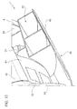
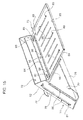
Figure 13 shows, in perspective, a first stage of the extraction of a laptop computer carried by the interchangeable module shown inFigure 11 ; -
Figure 14 shows only the interchangeable module illustrated inFigure 11 , during the first stage of extraction; -
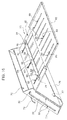
Figures 15 to 18 are similar toFigure 14 and show the successive stages of extraction. - In
Figure 1, 1 shows an object-holding drawer forming part of a dashboard of a motor vehicle (not shown) and comprising ashell 3 connected in a fixed position in a manner not illustrated to across-member 4 that supports the dashboard. - With reference to
Figure 2 , theshell 3 is made of a plastic material, reinforced preferably with fibreglass, and comprises aback wall 6, anupper wall 7 and twoside walls 8. Ametal bracket 10 is arranged along the outer surface of thewalls cross-member 4 both to stiffen theshell 3 and/or the connection of theshell 3 to thecross-member 4, and to support an interchangeable module, as will be better explained below. - The
walls 8 compriserespective edges 12 facing the passenger compartment and defining the sides of anopening 13 to access the space inside theshell 3. Thewalls 8 have twoslots 14, which extend from theedges 12 and are parallel to each other and comprise respective initialstraight sections 16 that are substantially horizontal and respective blind end sections 17. The sections 17 are facing downwards in relation to thesections 16 and define respective seats, which are aligned with respective retaining and supporting seats 18 made in theends 19 of thebracket 10. - With reference to
Figures 6 to 8 , theshell 3 houses amodule 20, which entirely occupies the space between thewalls 8 and comprises acontainer 21. Thecontainer 21 in turn comprises anupper wall 24, aback wall 25, and twoside walls 26, which define an opening 27 towards the passenger compartment. - The
walls 26 are connected to thewalls 8 and to thebracket 10 by means of a connectingdevice 30, which comprises two pins 31 (Figure 6 ), which are coaxial with each other along ahorizontal axis 32, overhang outwards in relation to thewalls 26, terminate withrespective flanges 33 of a larger diameter, engage in the seats 18 due to the effect of the weight of themodule 20 and are therefore supported by theends 19. Thedevice 30 also comprises tworesilient teeth 34 made in one piece with thewalls 8, and twoseats 35 made in thewalls 26 and engaged by theteeth 34. In particular, according toFigures 3 to 5 , themodule 20 is fitted by inserting thecontainer 20 into theshell 3 through theopening 13 and, at the same time, thepins 31 in theslots 14, with theflanges 33 arranged beyond thewalls 8 and with the opening 27 facing downwards. - The
pins 31 are made to slide down to the bottom of theslots 14, that is until they rest against theends 19 in the seats 18. In this way, themodule 20 remains held longitudinally by the seats 18. Themodule 20 is then rotated upwards about theaxis 32 elastically deforming theteeth 34 until theteeth 34 click into their respective seats 35 (Figure 7 ). - The
module 20 is removed by means of a special tool (not shown), which is used from outside by inserting it between thewalls teeth 34 are released from theseats 35. - In the final position in which the
teeth 34 engage in theseats 35, as shown inFigures 6 to 8 , thewall 25 is drawn towards thewall 6; the opening 27 coincides with the bottom part of theopening 13; and thewall 24 defines, together with thewalls compartment 38 accessible through anopening 39. The opening 39 coincides with the top part of theopening 13 and can be opened/closed by adoor 40, which is hinged to thewalls 8 in order to rotate about a horizontal axis 41 (Figures 2-4 ). - The
module 20 also comprises adoor 43 which is hinged to thewalls 26 by means of thepins 31 to rotate about theaxis 32 and open/close theopening 27. Therefore, thedoor 43 forms part of themodule 20. A releasable holding device (not shown) is provided to hold thedoor 43 in the closed position. - With particular reference to
Figure 8 , themodule 20 comprises abottom cradle 45 which is provided to stow objects, such asbottles 46, and is fixed in relation to thedoor 43 so as to pivot about theaxis 32, and covers the entire internal surface of thedoor 43. Thecontainer 21 and thecradle 45 are thermally insulated and define acompartment 47, which can be cooled by means of a flow of air from the motor vehicle's air-conditioning system, or by means of a known refrigeration system (not shown), comprising a condenser, an evaporator, an engine-compressor and a thermostat that automatically regulates the temperature in thecompartment 47 by switching the engine-compressor on and off. In particular, the refrigeration system is arranged in thecompartment 38 and carried by the wall 24 (in this case, thedoor 40 could be in the form of a fixed panel). - With reference to
Figure 6 , thedoor 43 has, in a fixed position, twoside walls 50 which slide along thewalls 26 during the opening/closing of thedoor 43. Thepins 31 extend axially overhanging thewalls 50, they are fixed in relation to thewalls 50 and engage in a rotating mannerrespective hinge seats 51 made in thewalls 26. Alternatively, thepins 31 are fixed in relation to thewalls 26 and engage in a rotating manner respective hinge seats made in thewalls 50. -
Figures 9 and10 illustrate amodule 60, whose constituent parts are indicated, where possible, by the same reference numbers asmodule 20. Themodule 60 differs from themodule 20 by the fact that thecontainer 21 supports anelectric machine 61 for the preparation of coffee (illustrated schematically), whose front surface is arranged in line with theopening 27. Themachine 61 is fixed, in a manner not shown, to thecontainer 21, it partially occupies the space between thewalls 26 and has twodrawers drawer 62 is configured to insert a coffee pod, while thedrawer 63 is configured to accommodate abeaker 64 into which themachine 61 causes the prepared coffee to pour. Thedoor 43 has nocradle 45 but carries, in a fixed position, a plurality of object-holding compartments 65 (to hold the pods, beakers, sugar and stirrers or teaspoons) which lie alongside themachine 61 in thecompartment 47 when thedoor 43 is in a closed position. -
Figures 11 to 18 illustrate amodule 70, whose constituent parts are shown, where possible, by the same reference numerals asmodules module 70 comprises aframe 71 defining acompartment 72 inclined upwards; and asupport 73, which can be extracted from thecompartment 72 through theopening 39 and is configured to support alaptop computer 75. - The
frame 71 comprises afin 76, which extends projecting upwards and in a position facing thedoor 43, it delimits the opening 27 with its upper edge, and defines arecess 77. Therecess 77 is capable of housing objects such as notebooks, papers and pens and can be accessed by opening thedoor 43. Thecompartment 72 is delimited laterally by twowalls 78, which form part of theframe 71 and are hinged to thedoor 43, in a way not shown, by means of thepins 31, and have projecting respectiveopposing attachment tabs 79 that snap lock onto the teeth 34 (Figure 12 ). - The
walls 78 have respective pairs ofguides 80 configured so as to cause thesupport 73 to slide outwards along an upwardly inclinedstraight section 81 and so as to rotate thesupport 73 towards a horizontal position along anextraction end section 82. - The
support 73 comprises arectangular tray 83, on which to rest thelaptop computer 75; a parallelrectangular plate 84 beneath thetray 83, and connected in a sliding manner to theguides 80; and alinkage 85 which connects thetray 83 to theplate 84 and comprises three connecting-pieces 88 all of the same length. The connecting-pieces 88 are connected in a rotating manner, at one of theirends 89, to thetray 83 and, at theopposite end 90, to theplate 84, so as substantially to define an articulated quadrilateral. In particular, theends 90 engage in a sliding manner in respectivestraight guides 92 made in theplate 84 parallel to the short sides of theplate 84 and are joined together by a connecting-piece 94, which is arranged along the upper face of theplate 84 and keeps theends 90 in positions that are aligned with each other while sliding/rotating in theguides 92. - Similarly, the
ends 89 engage in a sliding manner in respectivestraight guides 95 made in thetray 83 parallel to a short side of thetray 83 and are joined together by means of a connecting-piece 97 (Figures 13 and14 ), which is arranged along the lower face of thetray 83 and keeps theends 89 in positions that are aligned with each other while sliding/rotating in theguides 95. - In this way, after having extracted the
support 73 from the compartment 72 (Figures 13 and14 ) and having brought thesupport 73 to a horizontal position (Figure 15 ), it is possible to extract thetray 83 in relation to theplate 84 in a longitudinal direction, that is parallel to theguides 92, keeping theguides Figure 16 ), the laptop computer can be used by a passenger sitting on the front right-hand seat of the motor vehicle in front of thedrawer 1. - From this position, it is possible to slide the
tray 83 sideways in relation to theplate 84 by rotating the connecting-pieces 88 in relation to theplate 84 about vertical axes defined by the ends 90 (in a clockwise direction in the Figure) and in relation to thetray 83 about respective vertical axes defined by theends 89, but leaving the connecting-pieces guides Figure 17 ), the laptop computer can be used by a passenger sitting on a front middle seat of the motor vehicle. - Lastly, it is possible to rotate the
tray 83 in relation to the plate 84 (in a clockwise direction in the Figure), therefore rotating the connecting-pieces 94 and/or 97 in relation to theguides Figure 18 ), the laptop computer can be used by the driver sitting on the front left-hand seat of the motor vehicle. - During the fitting stage, the
module 70 is connected to theshell 3 in a similar manner to module 20: thedoor 40 is connected to thewalls 8 subsequently to close theopening 39 located above thedoor 43. - From the above it is clear that
modules drawer 1 by a user or in flexible outfitting of the motor vehicle during manufacture. - The fact that the
pins 31 are used both to hinge thedoor 43 and to connect themodule shell 3 simplifies the constructional characteristics and fitting. -
Modules module 70 succeeds in transporting a laptop computer in a compact and efficient manner. - Lastly, from the above it is clear that modifications and variants can be made to the
drawer 1 described without departing from the scope of protection of the present invention. - For example, the
top door 40 could form part of the interchangeable module and be hinged to thewalls 26. - As mentioned above, the
pins 31 could be carried by thewalls door 43. - Furthermore, the
shell 3 need not have anybracket 10 if it were rigid enough to support themodule
Claims (19)
- Module (20,60,70) for an object-holding drawer (1) of a dashboard of a motor vehicle; the module can be chosen from a plurality of different modules for accommodating different objects and comprising:- a container (21,71) defining an access opening (27);- attachment means (30) to connect the said container (21,71) in a fixed position and in an interchangeable manner to a shell (3);- a door (43) to open and close the said access opening (27);- two hinge elements (31) coaxial with each other along a horizontal axis (32) to hinge the said door (43) to the said container (21,71) about the said horizontal axis (32).
- Module according to claim 1, characterised in that the said hinge elements (31) form part of the said attachment means (30).
- Module according to claim 1 or 2, characterised in that the said hinge elements (31) are defined by pins that project axially outwards in relation to respective side walls (26,78) of the said container (21, 71) .
- Module according to claim 3, characterised in that the said pins (31) are fixed in relation to the said door (43) and pass through respective hinge seats (35) in the side walls (26).
- Module according to any of the preceding claims, characterised in that the said container (21) and/or the said door (43) are thermally insulated and define a cooled compartment (47).
- Module according to claim 5, characterised in that the said container (21) carries, on the outside of the said cooled compartment (47), a refrigeration system.
- Module according to any of claims 1 to 4, characterised in that it comprises a support (73) that can be extracted from the said container (71) and configured to carry a laptop computer (75).
- Module according to claim 7, characterised in that the said container (71) comprises a fin (76) pushing upwards, delimiting the said access opening (27) with its upper edge, and defining an object-holding recess (77) that can be accessed through the said access opening (27); it being possible to extract the said support (73) from the said container (71) through an opening (39) located above the said access opening (27).
- Module according to claim 7 or 8, characterised in that the said container (71) comprises guide means (80) configured so as to make the said support (73) slide upwards in a straight direction and so as to rotate the said support (73) towards a horizontal position along an extraction end section.
- Module according to claim 9, characterised in that the said support (73) comprises:- a tray (83), on which to rest the laptop computer (75);- a structure (84) connected in a sliding manner to the said guide means (80);- linkage means (85) that connect the said tray (83) to the said structure (84).
- Module according to claim 10, characterised in that the said linkage means (85) comprise at least two connecting-pieces (88) side-by-side and spaced apart and hinged at one end (89) to the said tray (83) and at the opposite end (90) to the said structure (84); the ends (89,90) of the said connecting pieces (88) sliding along the respective guides (95,92) made in the said tray (83) and in the said structure (84).
- Module according to any of claims 1 to 4, characterised in that the said container (21) supports an electric machine for the preparation of coffee (61).
- Module according to claim 12, characterised in that the said door (43) carries a plurality of object-holding compartments (65) which lie alongside the said electrical machine for the preparation of coffee (61).
- Object-holding drawer (1) of a dashboard of a motor vehicle; this drawer comprising:- a fixed shell (3);- an interchangeable module (20,60,70) made according to any of the preceding claims, fixed to the said shell (3) by the said attachment means (30) and defining an additional opening (39) positioned above the said access opening (27);- a panel (40) to close the said additional opening (39).
- Drawer according to claim 14, characterised in that the said shell (3) comprises two side walls (8) having respective slots (14), which are parallel to each other, have respective openings and end with respective blind portions (17) engaged by the said hinge elements (31).
- Drawer according to claim 14 or 15, characterised in that the said shell (3) is made of a plastic material and by the fact that it comprises two metal stiffening portions (19), arranged around the said shell (3) and engaged by the said hinge elements (31).
- Drawer according to any of claims 14 to 16, characterised in that it comprises snap-lock means (34) to connect together the said module (20,70) and the said shell (3).
- Drawer according to any of claims 14 to 17, characterised in that the said panel (40) is movable and in that the said additional opening (39) is an access for an object-holding compartment (38) defined from below by the said container (21) and from above by the said shell (3).
- Drawer according to any of claims 14 to 17, characterised in that the said panel (40) is movable and by the fact that the said additional opening (38) is an outlet for an extractable support (73) of a laptop computer (75).
Applications Claiming Priority (1)
| Application Number | Priority Date | Filing Date | Title |
|---|---|---|---|
| IT000211A ITTO20070211A1 (en) | 2007-03-22 | 2007-03-22 | INTERCHANGEABLE MODULE FOR A DRAWER-OBJECT DRAWER OF A DASHBOARD OF A MOTOR VEHICLE, AND OBJECT DRAWER PROVIDED WITH THIS INTERCHANGEABLE MODULE |
Publications (3)
| Publication Number | Publication Date |
|---|---|
| EP1972498A2 true EP1972498A2 (en) | 2008-09-24 |
| EP1972498A3 EP1972498A3 (en) | 2010-05-19 |
| EP1972498B1 EP1972498B1 (en) | 2016-05-11 |
Family
ID=38330799
Family Applications (1)
| Application Number | Title | Priority Date | Filing Date |
|---|---|---|---|
| EP08153161.8A Not-in-force EP1972498B1 (en) | 2007-03-22 | 2008-03-20 | Interchangeable module for an object-holding drawer of a dashboard of a motor vehicle and object-holding drawer fitted with such interchangeable module |
Country Status (3)
| Country | Link |
|---|---|
| US (1) | US7926861B2 (en) |
| EP (1) | EP1972498B1 (en) |
| IT (1) | ITTO20070211A1 (en) |
Cited By (3)
| Publication number | Priority date | Publication date | Assignee | Title |
|---|---|---|---|---|
| ITMI20081710A1 (en) * | 2008-09-26 | 2010-03-27 | Reco S R L | CONTAINER UNIT FOR COMMERCIAL AND / OR INDUSTRIAL VEHICLES |
| FR2965525A1 (en) * | 2010-10-04 | 2012-04-06 | Peugeot Citroen Automobiles Sa | Device for supporting and retaining object in object storage of fascia of automobile, has auxiliary support surface including front part rotatably coupled with auxiliary wall defining retractable retaining frontage for storage |
| CN111806356A (en) * | 2019-04-12 | 2020-10-23 | 大众汽车有限公司 | Housing system and electrical module for housing guided device and motor vehicle |
Families Citing this family (13)
| Publication number | Priority date | Publication date | Assignee | Title |
|---|---|---|---|---|
| US7762737B2 (en) * | 2006-11-09 | 2010-07-27 | The Boeing Company | System and method for stowage compartment pivot assembly |
| US20110084511A1 (en) * | 2009-10-13 | 2011-04-14 | Evans Gregg S | Automotive forward storage bin disappearing tray |
| US8740278B1 (en) | 2012-11-30 | 2014-06-03 | Nissan North America, Inc. | Suspended storage system for a vehicle glove box |
| JP6321426B2 (en) * | 2014-03-27 | 2018-05-09 | ダイハツ工業株式会社 | Vehicle compartment storage device for vehicle |
| US9862327B2 (en) | 2016-03-16 | 2018-01-09 | Ford Global Technologies Llc | Multi-purpose storage compartment |
| US9914398B1 (en) | 2017-03-09 | 2018-03-13 | Honda Motor Co., Ltd. | Vehicle storage compartment |
| US10266127B2 (en) | 2017-09-21 | 2019-04-23 | Toyota Motor Engineering & Manufacturing North America, Inc. | Retention features for vehicular gloveboxes |
| US10351068B2 (en) * | 2017-11-20 | 2019-07-16 | Ford Global Technologies, Llc | Vehicle glovebox assembly having separately operable inner and outer doors |
| JP6599042B1 (en) * | 2019-08-05 | 2019-10-30 | カルソニックカンセイ株式会社 | Pull-out storage box |
| KR102895505B1 (en) * | 2020-09-11 | 2025-12-04 | 현대모비스 주식회사 | Vehicle table device |
| DE102020132675A1 (en) * | 2020-12-08 | 2022-06-09 | Paul Hettich Gmbh & Co. Kg | storage element |
| DE102022210691A1 (en) * | 2022-10-11 | 2024-04-11 | Volkswagen Aktiengesellschaft | Component arrangement for a vehicle |
| US12280701B2 (en) | 2022-11-30 | 2025-04-22 | Ford Global Technologies, Llc | Deployable folding tray system for a vehicle |
Family Cites Families (25)
| Publication number | Priority date | Publication date | Assignee | Title |
|---|---|---|---|---|
| US2657967A (en) * | 1950-02-21 | 1953-11-03 | Everette V Gilchrist | Utility tray |
| JPS5522536A (en) * | 1978-08-04 | 1980-02-18 | Yasunari Hanekawa | Cold storage, heating, or heat insulating box built-in type globe box |
| JPS5663648U (en) * | 1979-10-24 | 1981-05-28 | ||
| US5197775A (en) * | 1991-12-13 | 1993-03-30 | Ford Motor Company | Glove compartment |
| DE4141239A1 (en) * | 1991-12-14 | 1993-06-17 | Audi Ag | MOVABLE GLOVE BOX |
| JPH10974A (en) * | 1996-04-16 | 1998-01-06 | Harness Sogo Gijutsu Kenkyusho:Kk | Table structure in the vehicle |
| US6060700A (en) * | 1996-06-03 | 2000-05-09 | Daniel Perlman | Microwave oven with removable storage cassette in dashboard of motor vehicle |
| AUPO305396A0 (en) * | 1996-10-18 | 1996-11-14 | South Australia Police | Support bracket |
| FR2755922B1 (en) * | 1996-11-21 | 1998-12-31 | Reydel Sa | INTERIOR ARRANGEMENT FOR VEHICLE SUCH AS, FOR EXAMPLE, MOTOR VEHICLE |
| FR2763301B1 (en) * | 1997-05-14 | 1999-07-16 | Reydel Sa | DASHBOARD FOR VEHICLE, ESPECIALLY MOTOR VEHICLE |
| US5971461A (en) * | 1997-06-05 | 1999-10-26 | Ford Motor Company | Automotive vehicle instrument panel assembly with modular glovebox |
| US6050628A (en) * | 1997-06-25 | 2000-04-18 | Ford Motor Company | Glove box for a vehicle |
| DE19942892B4 (en) * | 1999-09-08 | 2007-05-31 | Volkswagen Ag | Retractable filing tray, in particular clipboard in a vehicle interior |
| US6231099B1 (en) * | 1999-10-15 | 2001-05-15 | Delphi Technologies, Inc. | Reconfigurable glove box bin |
| FR2814410B1 (en) * | 2000-09-26 | 2003-02-21 | Visteon Systemes Interieurs | POCKET HOLDER, ESPECIALLY FOR A MOTOR VEHICLE |
| US20020158448A1 (en) * | 2001-04-26 | 2002-10-31 | Chidiebele Okonkwo | Modern automotive cockpit |
| DE10149402A1 (en) * | 2001-10-06 | 2003-04-17 | Porsche Ag | Device for holding beverage cans or the like. Containers in the interior of vehicles |
| DE102004006408A1 (en) * | 2004-02-10 | 2005-08-25 | Adam Opel Ag | Rail system for a glove box dashboard structure on a motor vehicle's co-driver's side forms a modular link between a glove box unit, one of a series of modules and a dashboard unit |
| US7293507B2 (en) * | 2004-04-02 | 2007-11-13 | International Automotive Components Group North America, Inc. | Portable tray for vehicle interior |
| DE102004053322B3 (en) * | 2004-11-04 | 2005-12-15 | Lisa Dräxlmaier GmbH | Dashboard storage cubbyhole cover for use in road vehicle has extension tray sliding in grooves in back of cover, and moved outward by linkage as cover is swung down from closed to open position |
| US7152898B2 (en) * | 2005-01-06 | 2006-12-26 | Lear Corporation | System and method for reducing vehicle noise |
| US7494170B2 (en) * | 2005-02-22 | 2009-02-24 | Gm Global Technology Operations, Inc. | Vehicle instrument panel having movable storage compartment |
| US7533919B2 (en) * | 2005-11-29 | 2009-05-19 | Faurecia Innenraum Systeme Gmbh | Storage compartment for a motor vehicle, glove compartment and dash board |
| US7726143B2 (en) * | 2006-12-21 | 2010-06-01 | Chrysler Group Llc | Vehicle cooled instrument panel compartment |
| US7543871B2 (en) * | 2006-12-22 | 2009-06-09 | Chrysler Llc | Center console |
-
2007
- 2007-03-22 IT IT000211A patent/ITTO20070211A1/en unknown
-
2008
- 2008-03-20 US US12/052,529 patent/US7926861B2/en not_active Expired - Fee Related
- 2008-03-20 EP EP08153161.8A patent/EP1972498B1/en not_active Not-in-force
Non-Patent Citations (1)
| Title |
|---|
| None |
Cited By (4)
| Publication number | Priority date | Publication date | Assignee | Title |
|---|---|---|---|---|
| ITMI20081710A1 (en) * | 2008-09-26 | 2010-03-27 | Reco S R L | CONTAINER UNIT FOR COMMERCIAL AND / OR INDUSTRIAL VEHICLES |
| FR2965525A1 (en) * | 2010-10-04 | 2012-04-06 | Peugeot Citroen Automobiles Sa | Device for supporting and retaining object in object storage of fascia of automobile, has auxiliary support surface including front part rotatably coupled with auxiliary wall defining retractable retaining frontage for storage |
| CN111806356A (en) * | 2019-04-12 | 2020-10-23 | 大众汽车有限公司 | Housing system and electrical module for housing guided device and motor vehicle |
| US11535169B2 (en) | 2019-04-12 | 2022-12-27 | Volkswagen Aktiengesellschaft | Receiving system for receiving at least one guided device, and an electric module, as well as a motor vehicle |
Also Published As
| Publication number | Publication date |
|---|---|
| EP1972498A3 (en) | 2010-05-19 |
| EP1972498B1 (en) | 2016-05-11 |
| US20080231065A1 (en) | 2008-09-25 |
| US7926861B2 (en) | 2011-04-19 |
| ITTO20070211A1 (en) | 2008-09-23 |
Similar Documents
| Publication | Publication Date | Title |
|---|---|---|
| US7926861B2 (en) | Interchangeable module for glove box of dashboard of motor vehicle and glove box fitted with such interchangeable module | |
| US6478204B2 (en) | Receptacle cover | |
| CN203727231U (en) | Container bearing assembly and multi-container bearing assembly | |
| US8196985B2 (en) | Console assembly | |
| US7104580B2 (en) | Floor console | |
| CN102414082B (en) | Transformable luggage storage compartment for an aircraft cabin | |
| US9862327B2 (en) | Multi-purpose storage compartment | |
| EP3415431A1 (en) | Aircraft passenger suite seating arrangement | |
| CN101003266A (en) | Storage structure in vehicle compartment | |
| CA1264465A (en) | Integrated console cup holder | |
| JP5662463B2 (en) | Tray mechanism with automatic beverage holding device | |
| CN111806349A (en) | Trunk device for vehicle | |
| CN102227338A (en) | Automobile glove compartment | |
| US7237816B1 (en) | Automotive center console with open front face | |
| US20070102945A1 (en) | Nesting console system | |
| US7147280B2 (en) | Holding receptacle for vehicles | |
| CN117774796A (en) | Vehicle center console and front seat components | |
| EP1999416B1 (en) | A refrigerating apparatus | |
| GB2509217A (en) | Cup holder for a motor vehicle | |
| KR20120047571A (en) | Tray for vehicle | |
| CN217227301U (en) | Vehicle with a steering wheel | |
| EP1939035A2 (en) | Front console for vehicles | |
| CN217945054U (en) | A vice instrument board assembly and vehicle for vehicle | |
| KR20100006177U (en) | Console-accepting place for bus | |
| KR20250120108A (en) | Console module and vehicle cockpit with the same |
Legal Events
| Date | Code | Title | Description |
|---|---|---|---|
| PUAI | Public reference made under article 153(3) epc to a published international application that has entered the european phase |
Free format text: ORIGINAL CODE: 0009012 |
|
| AK | Designated contracting states |
Kind code of ref document: A2 Designated state(s): AT BE BG CH CY CZ DE DK EE ES FI FR GB GR HR HU IE IS IT LI LT LU LV MC MT NL NO PL PT RO SE SI SK TR |
|
| AX | Request for extension of the european patent |
Extension state: AL BA MK RS |
|
| PUAL | Search report despatched |
Free format text: ORIGINAL CODE: 0009013 |
|
| AK | Designated contracting states |
Kind code of ref document: A3 Designated state(s): AT BE BG CH CY CZ DE DK EE ES FI FR GB GR HR HU IE IS IT LI LT LU LV MC MT NL NO PL PT RO SE SI SK TR |
|
| AX | Request for extension of the european patent |
Extension state: AL BA MK RS |
|
| 17P | Request for examination filed |
Effective date: 20101119 |
|
| AKX | Designation fees paid |
Designated state(s): AT BE BG CH CY CZ DE DK EE ES FI FR GB GR HR HU IE IS IT LI LT LU LV MC MT NL NO PL PT RO SE SI SK TR |
|
| RIC1 | Information provided on ipc code assigned before grant |
Ipc: B60R 7/06 20060101AFI20101228BHEP |
|
| 17Q | First examination report despatched |
Effective date: 20150122 |
|
| GRAP | Despatch of communication of intention to grant a patent |
Free format text: ORIGINAL CODE: EPIDOSNIGR1 |
|
| INTG | Intention to grant announced |
Effective date: 20151126 |
|
| GRAS | Grant fee paid |
Free format text: ORIGINAL CODE: EPIDOSNIGR3 |
|
| GRAA | (expected) grant |
Free format text: ORIGINAL CODE: 0009210 |
|
| AK | Designated contracting states |
Kind code of ref document: B1 Designated state(s): AT BE BG CH CY CZ DE DK EE ES FI FR GB GR HR HU IE IS IT LI LT LU LV MC MT NL NO PL PT RO SE SI SK TR |
|
| REG | Reference to a national code |
Ref country code: GB Ref legal event code: FG4D |
|
| REG | Reference to a national code |
Ref country code: CH Ref legal event code: EP |
|
| REG | Reference to a national code |
Ref country code: AT Ref legal event code: REF Ref document number: 798371 Country of ref document: AT Kind code of ref document: T Effective date: 20160515 |
|
| REG | Reference to a national code |
Ref country code: IE Ref legal event code: FG4D |
|
| REG | Reference to a national code |
Ref country code: DE Ref legal event code: R096 Ref document number: 602008044152 Country of ref document: DE |
|
| REG | Reference to a national code |
Ref country code: LT Ref legal event code: MG4D |
|
| REG | Reference to a national code |
Ref country code: NL Ref legal event code: MP Effective date: 20160511 |
|
| PG25 | Lapsed in a contracting state [announced via postgrant information from national office to epo] |
Ref country code: LT Free format text: LAPSE BECAUSE OF FAILURE TO SUBMIT A TRANSLATION OF THE DESCRIPTION OR TO PAY THE FEE WITHIN THE PRESCRIBED TIME-LIMIT Effective date: 20160511 Ref country code: FI Free format text: LAPSE BECAUSE OF FAILURE TO SUBMIT A TRANSLATION OF THE DESCRIPTION OR TO PAY THE FEE WITHIN THE PRESCRIBED TIME-LIMIT Effective date: 20160511 Ref country code: NL Free format text: LAPSE BECAUSE OF FAILURE TO SUBMIT A TRANSLATION OF THE DESCRIPTION OR TO PAY THE FEE WITHIN THE PRESCRIBED TIME-LIMIT Effective date: 20160511 Ref country code: NO Free format text: LAPSE BECAUSE OF FAILURE TO SUBMIT A TRANSLATION OF THE DESCRIPTION OR TO PAY THE FEE WITHIN THE PRESCRIBED TIME-LIMIT Effective date: 20160811 |
|
| REG | Reference to a national code |
Ref country code: AT Ref legal event code: MK05 Ref document number: 798371 Country of ref document: AT Kind code of ref document: T Effective date: 20160511 |
|
| PG25 | Lapsed in a contracting state [announced via postgrant information from national office to epo] |
Ref country code: LV Free format text: LAPSE BECAUSE OF FAILURE TO SUBMIT A TRANSLATION OF THE DESCRIPTION OR TO PAY THE FEE WITHIN THE PRESCRIBED TIME-LIMIT Effective date: 20160511 Ref country code: HR Free format text: LAPSE BECAUSE OF FAILURE TO SUBMIT A TRANSLATION OF THE DESCRIPTION OR TO PAY THE FEE WITHIN THE PRESCRIBED TIME-LIMIT Effective date: 20160511 Ref country code: ES Free format text: LAPSE BECAUSE OF FAILURE TO SUBMIT A TRANSLATION OF THE DESCRIPTION OR TO PAY THE FEE WITHIN THE PRESCRIBED TIME-LIMIT Effective date: 20160511 Ref country code: PT Free format text: LAPSE BECAUSE OF FAILURE TO SUBMIT A TRANSLATION OF THE DESCRIPTION OR TO PAY THE FEE WITHIN THE PRESCRIBED TIME-LIMIT Effective date: 20160912 Ref country code: GR Free format text: LAPSE BECAUSE OF FAILURE TO SUBMIT A TRANSLATION OF THE DESCRIPTION OR TO PAY THE FEE WITHIN THE PRESCRIBED TIME-LIMIT Effective date: 20160812 Ref country code: SE Free format text: LAPSE BECAUSE OF FAILURE TO SUBMIT A TRANSLATION OF THE DESCRIPTION OR TO PAY THE FEE WITHIN THE PRESCRIBED TIME-LIMIT Effective date: 20160511 |
|
| PG25 | Lapsed in a contracting state [announced via postgrant information from national office to epo] |
Ref country code: EE Free format text: LAPSE BECAUSE OF FAILURE TO SUBMIT A TRANSLATION OF THE DESCRIPTION OR TO PAY THE FEE WITHIN THE PRESCRIBED TIME-LIMIT Effective date: 20160511 Ref country code: CZ Free format text: LAPSE BECAUSE OF FAILURE TO SUBMIT A TRANSLATION OF THE DESCRIPTION OR TO PAY THE FEE WITHIN THE PRESCRIBED TIME-LIMIT Effective date: 20160511 Ref country code: DK Free format text: LAPSE BECAUSE OF FAILURE TO SUBMIT A TRANSLATION OF THE DESCRIPTION OR TO PAY THE FEE WITHIN THE PRESCRIBED TIME-LIMIT Effective date: 20160511 Ref country code: SK Free format text: LAPSE BECAUSE OF FAILURE TO SUBMIT A TRANSLATION OF THE DESCRIPTION OR TO PAY THE FEE WITHIN THE PRESCRIBED TIME-LIMIT Effective date: 20160511 Ref country code: RO Free format text: LAPSE BECAUSE OF FAILURE TO SUBMIT A TRANSLATION OF THE DESCRIPTION OR TO PAY THE FEE WITHIN THE PRESCRIBED TIME-LIMIT Effective date: 20160511 |
|
| REG | Reference to a national code |
Ref country code: DE Ref legal event code: R097 Ref document number: 602008044152 Country of ref document: DE |
|
| PG25 | Lapsed in a contracting state [announced via postgrant information from national office to epo] |
Ref country code: PL Free format text: LAPSE BECAUSE OF FAILURE TO SUBMIT A TRANSLATION OF THE DESCRIPTION OR TO PAY THE FEE WITHIN THE PRESCRIBED TIME-LIMIT Effective date: 20160511 Ref country code: BE Free format text: LAPSE BECAUSE OF FAILURE TO SUBMIT A TRANSLATION OF THE DESCRIPTION OR TO PAY THE FEE WITHIN THE PRESCRIBED TIME-LIMIT Effective date: 20160511 Ref country code: AT Free format text: LAPSE BECAUSE OF FAILURE TO SUBMIT A TRANSLATION OF THE DESCRIPTION OR TO PAY THE FEE WITHIN THE PRESCRIBED TIME-LIMIT Effective date: 20160511 |
|
| PLBE | No opposition filed within time limit |
Free format text: ORIGINAL CODE: 0009261 |
|
| STAA | Information on the status of an ep patent application or granted ep patent |
Free format text: STATUS: NO OPPOSITION FILED WITHIN TIME LIMIT |
|
| REG | Reference to a national code |
Ref country code: FR Ref legal event code: PLFP Year of fee payment: 10 |
|
| 26N | No opposition filed |
Effective date: 20170214 |
|
| PG25 | Lapsed in a contracting state [announced via postgrant information from national office to epo] |
Ref country code: SI Free format text: LAPSE BECAUSE OF FAILURE TO SUBMIT A TRANSLATION OF THE DESCRIPTION OR TO PAY THE FEE WITHIN THE PRESCRIBED TIME-LIMIT Effective date: 20160511 |
|
| REG | Reference to a national code |
Ref country code: CH Ref legal event code: PL |
|
| GBPC | Gb: european patent ceased through non-payment of renewal fee |
Effective date: 20170320 |
|
| PG25 | Lapsed in a contracting state [announced via postgrant information from national office to epo] |
Ref country code: MC Free format text: LAPSE BECAUSE OF FAILURE TO SUBMIT A TRANSLATION OF THE DESCRIPTION OR TO PAY THE FEE WITHIN THE PRESCRIBED TIME-LIMIT Effective date: 20160511 |
|
| REG | Reference to a national code |
Ref country code: IE Ref legal event code: MM4A |
|
| PG25 | Lapsed in a contracting state [announced via postgrant information from national office to epo] |
Ref country code: LU Free format text: LAPSE BECAUSE OF NON-PAYMENT OF DUE FEES Effective date: 20170320 |
|
| PG25 | Lapsed in a contracting state [announced via postgrant information from national office to epo] |
Ref country code: CH Free format text: LAPSE BECAUSE OF NON-PAYMENT OF DUE FEES Effective date: 20170331 Ref country code: IE Free format text: LAPSE BECAUSE OF NON-PAYMENT OF DUE FEES Effective date: 20170320 Ref country code: GB Free format text: LAPSE BECAUSE OF NON-PAYMENT OF DUE FEES Effective date: 20170320 Ref country code: LI Free format text: LAPSE BECAUSE OF NON-PAYMENT OF DUE FEES Effective date: 20170331 |
|
| REG | Reference to a national code |
Ref country code: FR Ref legal event code: PLFP Year of fee payment: 11 |
|
| PGFP | Annual fee paid to national office [announced via postgrant information from national office to epo] |
Ref country code: FR Payment date: 20180329 Year of fee payment: 11 Ref country code: IT Payment date: 20180319 Year of fee payment: 11 |
|
| PGFP | Annual fee paid to national office [announced via postgrant information from national office to epo] |
Ref country code: DE Payment date: 20180530 Year of fee payment: 11 |
|
| PG25 | Lapsed in a contracting state [announced via postgrant information from national office to epo] |
Ref country code: MT Free format text: LAPSE BECAUSE OF NON-PAYMENT OF DUE FEES Effective date: 20170320 |
|
| PG25 | Lapsed in a contracting state [announced via postgrant information from national office to epo] |
Ref country code: HU Free format text: LAPSE BECAUSE OF FAILURE TO SUBMIT A TRANSLATION OF THE DESCRIPTION OR TO PAY THE FEE WITHIN THE PRESCRIBED TIME-LIMIT; INVALID AB INITIO Effective date: 20080320 |
|
| PG25 | Lapsed in a contracting state [announced via postgrant information from national office to epo] |
Ref country code: BG Free format text: LAPSE BECAUSE OF FAILURE TO SUBMIT A TRANSLATION OF THE DESCRIPTION OR TO PAY THE FEE WITHIN THE PRESCRIBED TIME-LIMIT Effective date: 20160511 |
|
| REG | Reference to a national code |
Ref country code: DE Ref legal event code: R119 Ref document number: 602008044152 Country of ref document: DE |
|
| PG25 | Lapsed in a contracting state [announced via postgrant information from national office to epo] |
Ref country code: CY Free format text: LAPSE BECAUSE OF NON-PAYMENT OF DUE FEES Effective date: 20160511 |
|
| PG25 | Lapsed in a contracting state [announced via postgrant information from national office to epo] |
Ref country code: DE Free format text: LAPSE BECAUSE OF NON-PAYMENT OF DUE FEES Effective date: 20191001 |
|
| PG25 | Lapsed in a contracting state [announced via postgrant information from national office to epo] |
Ref country code: IT Free format text: LAPSE BECAUSE OF NON-PAYMENT OF DUE FEES Effective date: 20190320 Ref country code: FR Free format text: LAPSE BECAUSE OF NON-PAYMENT OF DUE FEES Effective date: 20190331 |
|
| PG25 | Lapsed in a contracting state [announced via postgrant information from national office to epo] |
Ref country code: TR Free format text: LAPSE BECAUSE OF FAILURE TO SUBMIT A TRANSLATION OF THE DESCRIPTION OR TO PAY THE FEE WITHIN THE PRESCRIBED TIME-LIMIT Effective date: 20160511 |
|
| PG25 | Lapsed in a contracting state [announced via postgrant information from national office to epo] |
Ref country code: IS Free format text: LAPSE BECAUSE OF FAILURE TO SUBMIT A TRANSLATION OF THE DESCRIPTION OR TO PAY THE FEE WITHIN THE PRESCRIBED TIME-LIMIT Effective date: 20160911 |