EP1972469A1 - Wireless-communication equipped vehicle - Google Patents
Wireless-communication equipped vehicle Download PDFInfo
- Publication number
- EP1972469A1 EP1972469A1 EP20070012046 EP07012046A EP1972469A1 EP 1972469 A1 EP1972469 A1 EP 1972469A1 EP 20070012046 EP20070012046 EP 20070012046 EP 07012046 A EP07012046 A EP 07012046A EP 1972469 A1 EP1972469 A1 EP 1972469A1
- Authority
- EP
- European Patent Office
- Prior art keywords
- pillar
- wireless
- equipped vehicle
- magnetic loss
- loss material
- Prior art date
- Legal status (The legal status is an assumption and is not a legal conclusion. Google has not performed a legal analysis and makes no representation as to the accuracy of the status listed.)
- Withdrawn
Links
- 239000000463 material Substances 0.000 claims abstract description 30
- 239000002184 metal Substances 0.000 claims abstract description 9
- 239000003973 paint Substances 0.000 claims description 15
- 239000011248 coating agent Substances 0.000 claims description 7
- 238000000576 coating method Methods 0.000 claims description 7
- 238000001514 detection method Methods 0.000 claims description 4
- 230000005684 electric field Effects 0.000 description 8
- 230000000694 effects Effects 0.000 description 7
- 230000001133 acceleration Effects 0.000 description 2
- 238000010276 construction Methods 0.000 description 2
- 238000010586 diagram Methods 0.000 description 2
- 239000005357 flat glass Substances 0.000 description 2
- 230000002159 abnormal effect Effects 0.000 description 1
- 239000002131 composite material Substances 0.000 description 1
- 230000001419 dependent effect Effects 0.000 description 1
- 238000009434 installation Methods 0.000 description 1
- 239000006247 magnetic powder Substances 0.000 description 1
- 238000004519 manufacturing process Methods 0.000 description 1
- 239000000203 mixture Substances 0.000 description 1
- 230000000149 penetrating effect Effects 0.000 description 1
- 229920000642 polymer Polymers 0.000 description 1
- 239000000843 powder Substances 0.000 description 1
- 239000011347 resin Substances 0.000 description 1
- 229920005989 resin Polymers 0.000 description 1
- 230000000007 visual effect Effects 0.000 description 1
Images



Classifications
-
- B—PERFORMING OPERATIONS; TRANSPORTING
- B60—VEHICLES IN GENERAL
- B60C—VEHICLE TYRES; TYRE INFLATION; TYRE CHANGING; CONNECTING VALVES TO INFLATABLE ELASTIC BODIES IN GENERAL; DEVICES OR ARRANGEMENTS RELATED TO TYRES
- B60C23/00—Devices for measuring, signalling, controlling, or distributing tyre pressure or temperature, specially adapted for mounting on vehicles; Arrangement of tyre inflating devices on vehicles, e.g. of pumps or of tanks; Tyre cooling arrangements
- B60C23/02—Signalling devices actuated by tyre pressure
- B60C23/04—Signalling devices actuated by tyre pressure mounted on the wheel or tyre
- B60C23/0408—Signalling devices actuated by tyre pressure mounted on the wheel or tyre transmitting the signals by non-mechanical means from the wheel or tyre to a vehicle body mounted receiver
- B60C23/0422—Signalling devices actuated by tyre pressure mounted on the wheel or tyre transmitting the signals by non-mechanical means from the wheel or tyre to a vehicle body mounted receiver characterised by the type of signal transmission means
- B60C23/0433—Radio signals
- B60C23/0435—Vehicle body mounted circuits, e.g. transceiver or antenna fixed to central console, door, roof, mirror or fender
-
- B—PERFORMING OPERATIONS; TRANSPORTING
- B60—VEHICLES IN GENERAL
- B60C—VEHICLE TYRES; TYRE INFLATION; TYRE CHANGING; CONNECTING VALVES TO INFLATABLE ELASTIC BODIES IN GENERAL; DEVICES OR ARRANGEMENTS RELATED TO TYRES
- B60C23/00—Devices for measuring, signalling, controlling, or distributing tyre pressure or temperature, specially adapted for mounting on vehicles; Arrangement of tyre inflating devices on vehicles, e.g. of pumps or of tanks; Tyre cooling arrangements
- B60C23/02—Signalling devices actuated by tyre pressure
- B60C23/04—Signalling devices actuated by tyre pressure mounted on the wheel or tyre
- B60C23/0408—Signalling devices actuated by tyre pressure mounted on the wheel or tyre transmitting the signals by non-mechanical means from the wheel or tyre to a vehicle body mounted receiver
- B60C23/0422—Signalling devices actuated by tyre pressure mounted on the wheel or tyre transmitting the signals by non-mechanical means from the wheel or tyre to a vehicle body mounted receiver characterised by the type of signal transmission means
- B60C23/0433—Radio signals
- B60C23/0435—Vehicle body mounted circuits, e.g. transceiver or antenna fixed to central console, door, roof, mirror or fender
- B60C23/0444—Antenna structures, control or arrangements thereof, e.g. for directional antennas, diversity antenna, antenna multiplexing or antennas integrated in fenders
Definitions
- This invention relates to a wireless-equipped vehicle including a metal body equipped with an interior wireless device which receives radio waves from outside the body.
- Wireless-equipped vehicles of the above-mentioned type have conventionally been known, equipped with receivers such as radio, television, an electronic toll collection (ETC) vehicle-mounted unit, keyless entry system or tire monitor system as an interior wireless device. It is difficult to mount antennas of all these interior wireless devices on the vehicle exterior from the viewpoints of installation space and costs. In view of this problem, some of the interior wireless devices receive external radio waves via antennas disposed in the vehicle body. See JP-A-2005-119370 and JP-A-2002-4676 , for example.
- ETC electronic toll collection
- an object of the present invention is to provide a wireless-equipped vehicle in which an interior wireless device is stably capable of receiving radio waves from outside a vehicle body.
- the present invention provides a wireless-equipped vehicle which comprises a vehicle body made of a metal and including a ceiling, a main body and a pillar connecting the ceiling and the main body, the pillar having a side face and an interior wireless device provided in the vehicle body to receive radio waves from outside the vehicle body, characterized by a magnetic loss material disposed on the side face of the pillar to limit AC current conduction between the ceiling and the main body.
- the wireless-equipped vehicle further comprises a coating member containing the magnetic loss material and covering the pillar.
- the magnetic loss material can be prevented from protruding from the pillar.
- the coating member may be a sheet affixed to the pillar or paint applied to the pillar.
- a block of the magnetic loss material may be provided between the pillar and an interior part covering the inside surface of the pillar.
- a generation of magnetic field around the pillar is limited by the magnetic loss material.
- the AC current conduction is limited between the ceiling and the main body through the pillar.
- the magnetic loss material preferably comprises a ferritic metal.
- the magnetic loss material may be disposed only on the inside surface of the pillar. Consequently, an exterior appearance of the wireless-equipped vehicle can be prevented from being spoiled by the magnetic loss material.
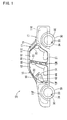
- FIG. 1 a wireless-equipped vehicle 10 of the embodiment is shown.
- the wireless-equipped vehicle 10 comprises a vehicle body 11 which is divided into an engine compartment 11F, a passenger compartment 11C and a trunk 11R.
- the top of the passenger compartment 11C is defined by a ceiling 20.
- Mounted between the ceiling 20 and a main body 21 are a pair of right and left front pillars 15, a pair of right and left center pillars 16 and a pair of right and left rear pillars 17.
- FIG. 1 shows only one of each pair.
- a front window glass 18 is mounted between the front pillars 15.
- a rear window glass 19 is mounted between the rear pillars 17.
- Two entrances 12 are defined between the front pillars 15 and the center pillars 16 and between the center pillars 16 and the rear pillars 17 respectively.
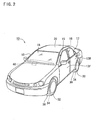
- Two front doors 13F closing and opening the front entrances 12 are pivotally mounted on hinges 12F (see FIG. 1 ) which are provided on the main body 21 so as to be located below the front pillars 15 respectively.
- Two rear doors 13R closing and opening the rear entrances 12 are pivotally mounted on hinges 12R (see FIG. 1 ) which are provided on vertically middle portions of the center pillars 16 respectively.
- the doors 13F and 13R have front end faces from which cables (not shown) of electrical components (not shown) within the doors 13F and 13R are drawn to be connected to the main body 21 or front pillars 15 respectively. Furthermore, insulating cushion rubber is attached to overall outer edges of the doors 13F and 13R.
- the doors 13F and 13R are insulated by the cushion rubber at portions other than the cables and hinges 12F and 12R thereof from the vehicle body 11 (that is, the ceiling 20, main body 21 and pillars 15 to 17).
- the pillars 15 to 17 have inside faces covered by interior parts 11N respectively as shown in FIG. 5 .
- a dashboard 14 is provided on a front part of the passenger compartment 11C as shown in FIG. 1 .
- a tire monitor device 66 is provided inside the dashboard 14.
- An interior wireless device 60 is provided as a part of the tire monitor device 66.
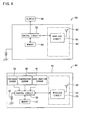
- the interior wireless device 60 comprises a wireless circuit 61 and an antenna 62 as shown in FIG. 4 .
- the tire monitor device 66 includes a control circuit 63, a memory 64 and a display 65 in addition to the interior wireless device 60.
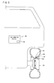
- the vehicle 10 is provided with four wheels 30 for example, though only one wheel is shown in FIG. 3 .
- Four tire pressure detectors 44 are mounted on the wheels 30 respectively.
- Exterior wireless devices 34 are provided which constitute a part of the tire pressure detectors 44 respectively.
- Each exterior wireless device 34 comprises a wireless circuit 35 and an antenna 36 as shown in FIG. 4 .
- Each tire pressure detector 44 includes a memory 37, a control circuit 38, a pressure sensor 39, a temperature sensor 40, an acceleration sensor 41, a button cell 42 all of which are enclosed in a case 43 besides the exterior wireless device 34.
- the case 43 is fixed to a proximal end of a tire valve 33 disposed within a tire 32.
- the interior and exterior wireless devices 60 and 34 of the embodiment are arranged so as to carry out modulation and demodulation with use of carrier waves in a band of 300 MHz, for example.
- An electrical conduction limiting sheet 22 (corresponding to a coating member or sheet in the invention) as shown in FIG. 5 is affixed to all of the front, center and rear pillars 15, 16 and 17 of the body 11 in order to carry out a good wireless communication between the tire monitor device 66 and the tire pressure detectors 44.
- the electrical conduction limiting sheet 22 is of composite materials of a polymer and a magnetic powder (ferritic metal powder, for example).
- the electrical conduction limiting sheet 22 is affixed to the pillars 15 to 17 so as to cover an entire periphery of each of the pillars 15 to 17. Furthermore, as shown in FIG. 1 , the electrical conduction limiting sheet 22 is affixed to each of the front and rear pillars 15 and 17 so as to extend over an entire vertical dimension thereof. The electrical conduction limiting sheet 22 affixed to each center pillar 16 extends from an upper end of each pillar 16 to the hinge 12R on which the door 13R is mounted. Additionally, the electrical conduction limiting sheet 22 is affixed to each of the pillars 15 to 17 so as to overlap a paint of each pillar and pigmentized as the same color as the paint.
- the control circuit 38 of each tire pressure detector 44 determines that the wireless-equipped vehicle 10 is in operation.
- the control circuit 38 executes a predetermined program stored on the memory 37.
- Pressure and temperature in each tire 32 are detected by the pressure sensor 39 and the temperature sensor 40 at a predetermined timing respectively.
- the control circuit 38 supplies to the exterior wireless device 34 the results of detection by the pressure sensor 39 and the temperature sensor 40 and an identification code stored on the memory 37.
- the detection results and identification code are modulated by the wireless circuit 35 of the exterior wireless device 34 into radio waves, which are delivered by the antenna 36.
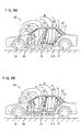
- a part of electric field E contained in the radio wave penetrates vertically through the wireless-equipped vehicle 10 as shown in FIGS. 6A and 6B . Furthermore, the direction of the electric field E is reversed in a predetermined period (300 MHz, for example) . More specifically, as shown in FIG. 6A , when the electric field E is directed from the ceiling 20 to a bottom wall 21T side of the main body 21, the potential at the ceiling 20 is higher than the potential at the bottom wall 21T. Accordingly, current is caused to flow from the ceiling 20 through the pillars 15 to 17 to the main body 21.
- each of the pillars 15 to 17 is covered by the electric conduction limiting sheet 22 comprised of the magnetic loss member in the wireless-equipped vehicle 10 of the embodiment. Accordingly, generation of magnetic filed is limited around each pillar, whereby the current conduction in each pillar is limited. As a result, the ceiling 20 and the bottom wall 21T of the main body 21 are prevented from being at the same potential instantaneously.
- the electric field E is also produced in the body 11. After the predetermined period, the direction of the electric field E produced from the exterior wireless device 34 is changed as shown by the change from FIG. 6A to FIG. 6B . Then, the potential of the ceiling 20 is lower than that of the bottom wall 21T. In this case, too, the current conduction is limited in each of the pillars 15 to 17 such that the electric field E is produced in the body 11.
- the electric field contained in the radio waves (electromagnetic waves) produced from the exterior wireless device 34 can also be produced in the vehicle body 11 since the shielding effect of the body 11 is limited.
- the interior wireless device 60 in the tire monitor device 66 receives the radio waves containing the aforesaid electric field E by the antenna 62 provided in the passenger compartment 11C.
- the wireless circuit 61 then demodulates the radio waves so that the results of detection of pressure and temperature and the identification code both contained in the radio waves are loaded into the control circuit 63.
- the control circuit 63 then compares the temperature and pressure of each tire 32 with a reference value stored on the memory 64, causing the display 65 to display presence of abnormal condition. Consequently, the information about pressure and temperature of each tire 32 can accurately be transmitted to the vehicle body 11 side.
- the electrical conduction limiting sheet 22 is provided on the pillars 15 to 17 connecting the ceiling 20 and the main body 21 of the vehicle body 11.
- the electrical conduction limiting sheet 22 limits the conduction of AC current between the ceiling 20 and the main body 21. Accordingly, since the shielding effect of the body 11 against radio waves is suppressed, the interior wireless device 60 can stably receive the radio waves from outside the body 11. Consequently, when the exterior wireless device 34 transmits information about pressure and temperature of each tire 32 on radio waves, the information can accurately be transmitted to the interior wireless device 60 in the body 11 side. Furthermore, since the magnetic loss material is contained in the electrical conduction limiting sheet 22, the material can be prevented from protruding from each of the pillars 15 to 17, whereupon the visual quality of the vehicle can be improved.
- FIG. 7 illustrates a second embodiment of the invention.
- an electrical conduction limiting paint 23 (corresponding to the coating member and a paint containing a magnetic loss material in the invention) is applied to all the pillars 15 to 17, instead of the electrical conduction limiting sheet 22 in the first embodiment.
- the electrical conduction limiting paint 23 contains the magnetic loss material and accordingly surrounds each pillar in the same manner as the electrical conduction limiting sheet 22.
- the electrical conduction limiting paint 23 can achieve the same effect as in the first embodiment.
- the electrical conduction limiting paint 23 can be used instead of the conventional paint, conventional pillars can readily be changed to new ones with the electrical conduction limiting paint 23.
- FIG. 8 illustrates a third embodiment of the invention.
- an electrical conduction limiting block 24 (corresponding to a block in the invention) is provided between each of the pillars 15 to 17 and an interior part 11N covering the inner face of each pillar instead of the electrical conduction limiting sheet 22 in the first embodiment.
- the electrical conduction limiting block 24 is a mass of magnetic loss material (ferritic metal, for example) and confronts the inner surface of each of the pillars 15 to 17.
- the third embodiment can achieve the same effect as the first embodiment. Furthermore, since the electrical conduction limiting block 24 is only mounted on the conventional wireless-equipped vehicle 10, conventional pillars can readily be changed. Additionally, since the electrical conduction limiting block 24 is disposed between each of the pillars 15 to 17 and the interior part 11N so as to be hidden, the interior appearance of the wireless-equipped vehicle 10 can be prevented form being spoiled.
- the ceiling 20 and the main body 21 are connected to each other by the front, center and rear pillars 15 to 17 in the wireless-equipped vehicle 10 of the first embodiment.
- the wireless-equipped vehicle 10 may have any number of pillars only if the magnetic loss material (electrical conduction limiting sheet 22, electrical conduction limiting paint 23 or electrical conduction limiting block 24, for example) in accordance with the invention is provided on the pillars.
- All the pillars 15 to 17 of the wireless-equipped vehicle 10 of the first to third embodiments are provided with the magnetic loss material (electrical conduction limiting sheet 22 or electrical conduction limiting paint 23, for example).
- the magnetic loss material electrical conduction limiting sheet 22 or electrical conduction limiting paint 23, for example.
- a part of the pillars may be provided with the magnetic loss material. Even in this case, the shielding effect of the body 11 can be suppressed as compared with the case where the pillars are provided with no magnetic loss material.
- the magnetic loss material (electrical conduction limiting sheet 22, electrical conduction limiting paint 23 or electrical conduction limiting block 24, for example) may be disposed on a part of vertical dimension of each pillar or an overall vertical dimension of each pillar. Alternatively, the magnetic loss material may be disposed on a plurality of separate parts of vertical dimension of each pillar.
- the magnetic loss material (electrical conduction limiting sheet 22 or electrical conduction limiting paint 23, for example) may be disposed on a part of the periphery of each pillar or an overall periphery of each pillar. Alternatively, the magnetic loss material may be disposed on a plurality of separate parts of periphery of each pillar.
- the electrical conduction limiting block 24 is a mass of ferritic metal which is a magnetic loss material in the third embodiment.
- the block in the present invention may be a mass of resin or rubber each containing the magnetic loss material, for example.
- the interior wireless device 60 is provided as the tire monitor device 66 in the first embodiment.
- the invention may be applied to the wireless-equipped vehicle 10 which is provided with an interior wireless device such as radio, television, an electronic toll collection (ETC) vehicle-mounted unit or keyless entry system.
- ETC electronic toll collection
Landscapes
- Engineering & Computer Science (AREA)
- Mechanical Engineering (AREA)
- Body Structure For Vehicles (AREA)
- Shielding Devices Or Components To Electric Or Magnetic Fields (AREA)
Abstract
A wireless-equipped vehicle (10) includes a vehicle body (11) made of a metal and including a ceiling (20), a main body (21) and a pillar (15-17) connecting the ceiling (20) and the main body (21), the pillar (15-17) having a side face, an interior wireless device (60) located in the vehicle body (11) to receive radio waves from outside the vehicle body (11), and a magnetic loss material (22-24) disposed on the side face of the pillar (15-17) to limit AC current conduction between the ceiling (20) and the main body (21).
Description
- This invention relates to a wireless-equipped vehicle including a metal body equipped with an interior wireless device which receives radio waves from outside the body.
- Wireless-equipped vehicles of the above-mentioned type have conventionally been known, equipped with receivers such as radio, television, an electronic toll collection (ETC) vehicle-mounted unit, keyless entry system or tire monitor system as an interior wireless device. It is difficult to mount antennas of all these interior wireless devices on the vehicle exterior from the viewpoints of installation space and costs. In view of this problem, some of the interior wireless devices receive external radio waves via antennas disposed in the vehicle body. See
JP-A-2005-119370 JP-A-2002-4676 - However, the intensity of radio waves from vehicle exterior is reduced by a shielding effect of the vehicle body when the radio waves arrive at the vehicle interior. As a result, there is a possibility that each interior wireless device having an antenna in the vehicle interior cannot receive radio waves stably.
- Therefore, an object of the present invention is to provide a wireless-equipped vehicle in which an interior wireless device is stably capable of receiving radio waves from outside a vehicle body.
- The present invention provides a wireless-equipped vehicle which comprises a vehicle body made of a metal and including a ceiling, a main body and a pillar connecting the ceiling and the main body, the pillar having a side face and an interior wireless device provided in the vehicle body to receive radio waves from outside the vehicle body, characterized by a magnetic loss material disposed on the side face of the pillar to limit AC current conduction between the ceiling and the main body.
- In the above-described construction, a generation of magnetic field around the pillar is limited by the magnetic loss material. Accordingly, the AC current is prevented from flowing through the pillar between the ceiling and the main body. Consequently, since the shielding effect of the vehicle body is suppressed, the interior wireless device can stably receive the radio wave from outside the vehicle body.
- In a preferred embodiment, the wireless-equipped vehicle further comprises a coating member containing the magnetic loss material and covering the pillar. As a result, the magnetic loss material can be prevented from protruding from the pillar. Furthermore, the coating member may be a sheet affixed to the pillar or paint applied to the pillar.
- Furthermore, a block of the magnetic loss material may be provided between the pillar and an interior part covering the inside surface of the pillar. In this case, too, a generation of magnetic field around the pillar is limited by the magnetic loss material. Accordingly, the AC current conduction is limited between the ceiling and the main body through the pillar. The magnetic loss material preferably comprises a ferritic metal.
- Additionally, the magnetic loss material may be disposed only on the inside surface of the pillar. Consequently, an exterior appearance of the wireless-equipped vehicle can be prevented from being spoiled by the magnetic loss material.
- The invention will be described, merely by way of example, with reference to the accompanying drawings, in which:
-
FIG. 1 is a side view of a wireless-equipped vehicle in accordance with one embodiment of the invention; -
FIG. 2 is a perspective view of the wireless-equipped vehicle; -
FIG. 3 is a conceptual diagram of the wireless-equipped vehicle showing a tire pressure detector mounted on a wheel; -
FIG. 4 is a block diagram showing electrical arrangement of the tire pressure detector and a tire monitor; -
FIG. 5 is a sectional view of a pillar; -
FIGS. 6A and 6B are conceptual views of a magnetic field penetrating through the wireless-equipped vehicle; -
FIG. 7 is a sectional view of a pillar in accordance with a second embodiment; and -
FIG. 8 is a sectional view of a pillar in accordance with a third embodiment. - One embodiment of the present invention will be described with reference to
FIGS. 1 to 6 . Referring toFIG. 1 , a wireless-equippedvehicle 10 of the embodiment is shown. The wireless-equippedvehicle 10 comprises a vehicle body 11 which is divided into anengine compartment 11F, apassenger compartment 11C and atrunk 11R. The top of thepassenger compartment 11C is defined by aceiling 20. Mounted between theceiling 20 and amain body 21 are a pair of right and leftfront pillars 15, a pair of right andleft center pillars 16 and a pair of right and leftrear pillars 17.FIG. 1 shows only one of each pair. - A
front window glass 18 is mounted between thefront pillars 15. Arear window glass 19 is mounted between therear pillars 17. Twoentrances 12 are defined between thefront pillars 15 and thecenter pillars 16 and between thecenter pillars 16 and therear pillars 17 respectively. Twofront doors 13F (seeFIG. 2 ) closing and opening thefront entrances 12 are pivotally mounted onhinges 12F (seeFIG. 1 ) which are provided on themain body 21 so as to be located below thefront pillars 15 respectively. Tworear doors 13R (seeFIG. 2 ) closing and opening therear entrances 12 are pivotally mounted onhinges 12R (seeFIG. 1 ) which are provided on vertically middle portions of thecenter pillars 16 respectively. - The
doors doors main body 21 orfront pillars 15 respectively. Furthermore, insulating cushion rubber is attached to overall outer edges of thedoors doors ceiling 20,main body 21 andpillars 15 to 17). Thepillars 15 to 17 have inside faces covered byinterior parts 11N respectively as shown inFIG. 5 . - A
dashboard 14 is provided on a front part of thepassenger compartment 11C as shown inFIG. 1 . Atire monitor device 66 is provided inside thedashboard 14. An interiorwireless device 60 is provided as a part of thetire monitor device 66. The interiorwireless device 60 comprises awireless circuit 61 and anantenna 62 as shown inFIG. 4 . Thetire monitor device 66 includes acontrol circuit 63, amemory 64 and adisplay 65 in addition to the interiorwireless device 60. - The
vehicle 10 is provided with fourwheels 30 for example, though only one wheel is shown inFIG. 3 . Fourtire pressure detectors 44 are mounted on thewheels 30 respectively. Exteriorwireless devices 34 are provided which constitute a part of thetire pressure detectors 44 respectively. Each exteriorwireless device 34 comprises awireless circuit 35 and anantenna 36 as shown inFIG. 4 . Eachtire pressure detector 44 includes amemory 37, acontrol circuit 38, apressure sensor 39, atemperature sensor 40, anacceleration sensor 41, abutton cell 42 all of which are enclosed in acase 43 besides the exteriorwireless device 34. Thecase 43 is fixed to a proximal end of atire valve 33 disposed within atire 32. The interior and exteriorwireless devices - An electrical conduction limiting sheet 22 (corresponding to a coating member or sheet in the invention) as shown in
FIG. 5 is affixed to all of the front, center andrear pillars tire monitor device 66 and thetire pressure detectors 44. The electricalconduction limiting sheet 22 is of composite materials of a polymer and a magnetic powder (ferritic metal powder, for example). - The electrical
conduction limiting sheet 22 is affixed to thepillars 15 to 17 so as to cover an entire periphery of each of thepillars 15 to 17. Furthermore, as shown inFIG. 1 , the electricalconduction limiting sheet 22 is affixed to each of the front andrear pillars conduction limiting sheet 22 affixed to eachcenter pillar 16 extends from an upper end of eachpillar 16 to thehinge 12R on which thedoor 13R is mounted. Additionally, the electricalconduction limiting sheet 22 is affixed to each of thepillars 15 to 17 so as to overlap a paint of each pillar and pigmentized as the same color as the paint. - The operation of the wireless-equipped
vehicle 10 will now be described. When theacceleration sensor 41 detects rotation of thewheel 30, thecontrol circuit 38 of eachtire pressure detector 44 determines that the wireless-equippedvehicle 10 is in operation. In this case, thecontrol circuit 38 executes a predetermined program stored on thememory 37. Pressure and temperature in eachtire 32 are detected by thepressure sensor 39 and thetemperature sensor 40 at a predetermined timing respectively. Thecontrol circuit 38 supplies to theexterior wireless device 34 the results of detection by thepressure sensor 39 and thetemperature sensor 40 and an identification code stored on thememory 37. The detection results and identification code are modulated by thewireless circuit 35 of theexterior wireless device 34 into radio waves, which are delivered by theantenna 36. - Upon output of the radio waves from the
exterior wireless device 34, a part of electric field E contained in the radio wave penetrates vertically through the wireless-equippedvehicle 10 as shown inFIGS. 6A and 6B . Furthermore, the direction of the electric field E is reversed in a predetermined period (300 MHz, for example) . More specifically, as shown inFIG. 6A , when the electric field E is directed from theceiling 20 to abottom wall 21T side of themain body 21, the potential at theceiling 20 is higher than the potential at thebottom wall 21T. Accordingly, current is caused to flow from theceiling 20 through thepillars 15 to 17 to themain body 21. - However, each of the
pillars 15 to 17 is covered by the electricconduction limiting sheet 22 comprised of the magnetic loss member in the wireless-equippedvehicle 10 of the embodiment. Accordingly, generation of magnetic filed is limited around each pillar, whereby the current conduction in each pillar is limited. As a result, theceiling 20 and thebottom wall 21T of themain body 21 are prevented from being at the same potential instantaneously. The electric field E is also produced in the body 11. After the predetermined period, the direction of the electric field E produced from theexterior wireless device 34 is changed as shown by the change fromFIG. 6A to FIG. 6B . Then, the potential of theceiling 20 is lower than that of thebottom wall 21T. In this case, too, the current conduction is limited in each of thepillars 15 to 17 such that the electric field E is produced in the body 11. - As obvious from the foregoing, the electric field contained in the radio waves (electromagnetic waves) produced from the
exterior wireless device 34 can also be produced in the vehicle body 11 since the shielding effect of the body 11 is limited. Theinterior wireless device 60 in thetire monitor device 66 receives the radio waves containing the aforesaid electric field E by theantenna 62 provided in thepassenger compartment 11C. Thewireless circuit 61 then demodulates the radio waves so that the results of detection of pressure and temperature and the identification code both contained in the radio waves are loaded into thecontrol circuit 63. Thecontrol circuit 63 then compares the temperature and pressure of eachtire 32 with a reference value stored on thememory 64, causing thedisplay 65 to display presence of abnormal condition. Consequently, the information about pressure and temperature of eachtire 32 can accurately be transmitted to the vehicle body 11 side. - According to the above-described wireless-equipped
vehicle 10, the electricalconduction limiting sheet 22 is provided on thepillars 15 to 17 connecting theceiling 20 and themain body 21 of the vehicle body 11. The electricalconduction limiting sheet 22 limits the conduction of AC current between theceiling 20 and themain body 21. Accordingly, since the shielding effect of the body 11 against radio waves is suppressed, theinterior wireless device 60 can stably receive the radio waves from outside the body 11. Consequently, when theexterior wireless device 34 transmits information about pressure and temperature of eachtire 32 on radio waves, the information can accurately be transmitted to theinterior wireless device 60 in the body 11 side. Furthermore, since the magnetic loss material is contained in the electricalconduction limiting sheet 22, the material can be prevented from protruding from each of thepillars 15 to 17, whereupon the visual quality of the vehicle can be improved. -
FIG. 7 illustrates a second embodiment of the invention. In the second embodiment, an electrical conduction limiting paint 23 (corresponding to the coating member and a paint containing a magnetic loss material in the invention) is applied to all thepillars 15 to 17, instead of the electricalconduction limiting sheet 22 in the first embodiment. The electricalconduction limiting paint 23 contains the magnetic loss material and accordingly surrounds each pillar in the same manner as the electricalconduction limiting sheet 22. As a result, the electricalconduction limiting paint 23 can achieve the same effect as in the first embodiment. Furthermore, since the electricalconduction limiting paint 23 can be used instead of the conventional paint, conventional pillars can readily be changed to new ones with the electricalconduction limiting paint 23. -
FIG. 8 illustrates a third embodiment of the invention. In the third embodiment, an electrical conduction limiting block 24 (corresponding to a block in the invention) is provided between each of thepillars 15 to 17 and aninterior part 11N covering the inner face of each pillar instead of the electricalconduction limiting sheet 22 in the first embodiment. The electricalconduction limiting block 24 is a mass of magnetic loss material (ferritic metal, for example) and confronts the inner surface of each of thepillars 15 to 17. - The above-described construction also limits the production of magnetic field around the
pillars 15 to 17. Accordingly, the third embodiment can achieve the same effect as the first embodiment. Furthermore, since the electricalconduction limiting block 24 is only mounted on the conventional wireless-equippedvehicle 10, conventional pillars can readily be changed. Additionally, since the electricalconduction limiting block 24 is disposed between each of thepillars 15 to 17 and theinterior part 11N so as to be hidden, the interior appearance of the wireless-equippedvehicle 10 can be prevented form being spoiled. - The invention should not be limited to the foregoing embodiments. For example, the following embodiments encompass the technical scope of the present invention. Furthermore, the following embodiments may be modified without departing from the gist of the invention.
- The
ceiling 20 and themain body 21 are connected to each other by the front, center andrear pillars 15 to 17 in the wireless-equippedvehicle 10 of the first embodiment. However, the wireless-equippedvehicle 10 may have any number of pillars only if the magnetic loss material (electricalconduction limiting sheet 22, electricalconduction limiting paint 23 or electricalconduction limiting block 24, for example) in accordance with the invention is provided on the pillars. - All the
pillars 15 to 17 of the wireless-equippedvehicle 10 of the first to third embodiments are provided with the magnetic loss material (electricalconduction limiting sheet 22 or electricalconduction limiting paint 23, for example). However, a part of the pillars may be provided with the magnetic loss material. Even in this case, the shielding effect of the body 11 can be suppressed as compared with the case where the pillars are provided with no magnetic loss material. - The magnetic loss material (electrical
conduction limiting sheet 22, electricalconduction limiting paint 23 or electricalconduction limiting block 24, for example) may be disposed on a part of vertical dimension of each pillar or an overall vertical dimension of each pillar. Alternatively, the magnetic loss material may be disposed on a plurality of separate parts of vertical dimension of each pillar. - The magnetic loss material (electrical
conduction limiting sheet 22 or electricalconduction limiting paint 23, for example) may be disposed on a part of the periphery of each pillar or an overall periphery of each pillar. Alternatively, the magnetic loss material may be disposed on a plurality of separate parts of periphery of each pillar. - The electrical
conduction limiting block 24 is a mass of ferritic metal which is a magnetic loss material in the third embodiment. However, the block in the present invention may be a mass of resin or rubber each containing the magnetic loss material, for example. - The
interior wireless device 60 is provided as thetire monitor device 66 in the first embodiment. However, the invention may be applied to the wireless-equippedvehicle 10 which is provided with an interior wireless device such as radio, television, an electronic toll collection (ETC) vehicle-mounted unit or keyless entry system. - It is explicitly stated that all features disclosed in the description and/or the claims are intended to be disclosed separately and independently from each other for the purpose of original disclosure as well as for the purpose of restricting the claimed invention dependent of the compositions of the features in the embodiments and/or the claims. It is explicitly stated that all value ranges or indications of groups of entities disclose every possible intermediate value or intermediate entity for the purpose of original disclosure as well as for the purpose of restricting the claimed invention, in particular as limits of value ranges.
Claims (8)
- A wireless-equipped vehicle which comprises a vehicle body (11) made of a metal and including a ceiling (20), a main body (21) and a pillar (15-17) connecting the ceiling (20) and the main body (21), the pillar having a side face and an interior wireless device (60) provided in the vehicle body (11) to receive radio waves from outside the vehicle body (11), characterized by a magnetic loss material (22-24) disposed on the side face of the pillar (15-17) to limit AC current conduction between the ceiling (20) and the main body (21).
- The wireless-equipped vehicle according to claim 1, further characterized by a coating member (22, 23) containing the magnetic loss material (22, 23) and covering the pillar (15 to 17) .
- The wireless-equipped vehicle according to claim 2, characterized in that the coating member (22) comprises a sheet (22) affixed to the pillar (15-17).
- The wireless-equipped vehicle according to claim 2, characterized in that the coating member (23) comprises paint (23) applied to the pillar (15-17).
- The wireless-equipped vehicle according to claim 1, characterized in that the pillar (15-17) includes an inside surface covered with an interior part (11N), and the magnetic loss material (24) comprises a block (24) provided between the pillar (15-17) and the interior part (11N).
- The wireless-equipped vehicle according to any one of claims 1 to 5, characterized in that the magnetic loss material (22-24) comprises a ferritic metal.
- The wireless-equipped vehicle according to any one of claims 1 to 6, characterized in that the pillar (15-17) includes an inside surface, and the magnetic loss material (22-24) is disposed only on the inside surface of the pillar (15-17).
- The wireless-equipped vehicle according to any one of claims 1 to 7, further characterized by at least one wheel (30) and one tire (32) mounted on the wheel (30) and an exterior wireless device (34) mounted on the wheel (30) for detecting pressure in the tire (32) and supplying a result of detection as a radio wave, and in that the interior wireless device (60) receives the radio wave supplied by the exterior wireless device (34).
Applications Claiming Priority (1)
| Application Number | Priority Date | Filing Date | Title |
|---|---|---|---|
| JP2007076072A JP2008230536A (en) | 2007-03-23 | 2007-03-23 | Vehicle equipped with wireless device |
Publications (1)
| Publication Number | Publication Date |
|---|---|
| EP1972469A1 true EP1972469A1 (en) | 2008-09-24 |
Family
ID=39619242
Family Applications (1)
| Application Number | Title | Priority Date | Filing Date |
|---|---|---|---|
| EP20070012046 Withdrawn EP1972469A1 (en) | 2007-03-23 | 2007-06-20 | Wireless-communication equipped vehicle |
Country Status (3)
| Country | Link |
|---|---|
| US (1) | US20080231077A1 (en) |
| EP (1) | EP1972469A1 (en) |
| JP (1) | JP2008230536A (en) |
Families Citing this family (1)
| Publication number | Priority date | Publication date | Assignee | Title |
|---|---|---|---|---|
| CN101954898B (en) * | 2010-09-13 | 2013-01-02 | 庞磊 | Vehicle spare wheel wireless burglar alarm |
Citations (2)
| Publication number | Priority date | Publication date | Assignee | Title |
|---|---|---|---|---|
| EP0831685A2 (en) * | 1996-09-19 | 1998-03-25 | Daido Tokushuko Kabushiki Kaisha | Magnetic shield sheet and method for manufacturing thereof, and cable using the sheet |
| JP2005119370A (en) * | 2003-10-14 | 2005-05-12 | Pacific Ind Co Ltd | Transmitter of tire condition monitoring device |
-
2007
- 2007-03-23 JP JP2007076072A patent/JP2008230536A/en active Pending
- 2007-06-15 US US11/812,171 patent/US20080231077A1/en not_active Abandoned
- 2007-06-20 EP EP20070012046 patent/EP1972469A1/en not_active Withdrawn
Patent Citations (2)
| Publication number | Priority date | Publication date | Assignee | Title |
|---|---|---|---|---|
| EP0831685A2 (en) * | 1996-09-19 | 1998-03-25 | Daido Tokushuko Kabushiki Kaisha | Magnetic shield sheet and method for manufacturing thereof, and cable using the sheet |
| JP2005119370A (en) * | 2003-10-14 | 2005-05-12 | Pacific Ind Co Ltd | Transmitter of tire condition monitoring device |
Also Published As
| Publication number | Publication date |
|---|---|
| US20080231077A1 (en) | 2008-09-25 |
| JP2008230536A (en) | 2008-10-02 |
Similar Documents
| Publication | Publication Date | Title |
|---|---|---|
| CN107914667B (en) | Keyless entry/start system | |
| US9595753B2 (en) | Antenna arrangement structure for vehicle communication apparatus | |
| JP7131193B2 (en) | Position determination system | |
| US6933831B2 (en) | Door handle for vehicle | |
| KR100800374B1 (en) | Vehicle human body detection device | |
| US6118410A (en) | Automobile roof antenna shelf | |
| JP6074744B2 (en) | In-vehicle charger and vehicle equipped with the same | |
| JP2022082562A (en) | Position determination system for vehicle, and communication system for vehicle | |
| US6812900B2 (en) | Vehicle seating system capable of receiving and transmitting radio frequency signals | |
| EP3446293A1 (en) | Control system and method for a vehicle | |
| US20220043100A1 (en) | Positioning system | |
| JP4650694B2 (en) | Vehicle handle | |
| JP2005186862A (en) | Vehicle communication device | |
| EP1921708A1 (en) | Wave transmitting/receiving structure for vehicle antennas | |
| CN113043965A (en) | Electric component mounting structure | |
| US20080231077A1 (en) | Wireless-equipped vehicle | |
| JP5088026B2 (en) | Smart keyless entry system | |
| US10988114B2 (en) | Method for activating at least one function of a piece of equipment of a vehicle | |
| US20090262032A1 (en) | Glass antenna for car | |
| KR101743646B1 (en) | Smart key system implemented using by three antennas and vehicle control method in control unit of the system | |
| JP2015116970A (en) | Information display window for vehicle | |
| EP2311137B1 (en) | Antenna assembly for a motor vehicle | |
| WO1998016905A1 (en) | A radio communication unit for vehicles | |
| JP2003127790A (en) | Meter device | |
| JPH07131223A (en) | Upholstery for automobile |
Legal Events
| Date | Code | Title | Description |
|---|---|---|---|
| PUAI | Public reference made under article 153(3) epc to a published international application that has entered the european phase |
Free format text: ORIGINAL CODE: 0009012 |
|
| AK | Designated contracting states |
Kind code of ref document: A1 Designated state(s): AT BE BG CH CY CZ DE DK EE ES FI FR GB GR HU IE IS IT LI LT LU LV MC MT NL PL PT RO SE SI SK TR |
|
| AX | Request for extension of the european patent |
Extension state: AL BA HR MK RS |
|
| AKX | Designation fees paid | ||
| STAA | Information on the status of an ep patent application or granted ep patent |
Free format text: STATUS: THE APPLICATION IS DEEMED TO BE WITHDRAWN |
|
| 18D | Application deemed to be withdrawn |
Effective date: 20090325 |
|
| REG | Reference to a national code |
Ref country code: DE Ref legal event code: 8566 |