EP1972458A2 - Ink ribbon cassette and printing apparatus - Google Patents
Ink ribbon cassette and printing apparatus Download PDFInfo
- Publication number
- EP1972458A2 EP1972458A2 EP08101814A EP08101814A EP1972458A2 EP 1972458 A2 EP1972458 A2 EP 1972458A2 EP 08101814 A EP08101814 A EP 08101814A EP 08101814 A EP08101814 A EP 08101814A EP 1972458 A2 EP1972458 A2 EP 1972458A2
- Authority
- EP
- European Patent Office
- Prior art keywords
- ink ribbon
- embankment
- lodging section
- cover
- lodging
- Prior art date
- Legal status (The legal status is an assumption and is not a legal conclusion. Google has not performed a legal analysis and makes no representation as to the accuracy of the status listed.)
- Granted
Links
Images




Classifications
-
- B—PERFORMING OPERATIONS; TRANSPORTING
- B41—PRINTING; LINING MACHINES; TYPEWRITERS; STAMPS
- B41J—TYPEWRITERS; SELECTIVE PRINTING MECHANISMS, i.e. MECHANISMS PRINTING OTHERWISE THAN FROM A FORME; CORRECTION OF TYPOGRAPHICAL ERRORS
- B41J32/00—Ink-ribbon cartridges
-
- B—PERFORMING OPERATIONS; TRANSPORTING
- B41—PRINTING; LINING MACHINES; TYPEWRITERS; STAMPS
- B41J—TYPEWRITERS; SELECTIVE PRINTING MECHANISMS, i.e. MECHANISMS PRINTING OTHERWISE THAN FROM A FORME; CORRECTION OF TYPOGRAPHICAL ERRORS
- B41J32/00—Ink-ribbon cartridges
- B41J32/02—Ink-ribbon cartridges for endless ribbons
-
- B—PERFORMING OPERATIONS; TRANSPORTING
- B41—PRINTING; LINING MACHINES; TYPEWRITERS; STAMPS
- B41J—TYPEWRITERS; SELECTIVE PRINTING MECHANISMS, i.e. MECHANISMS PRINTING OTHERWISE THAN FROM A FORME; CORRECTION OF TYPOGRAPHICAL ERRORS
- B41J31/00—Ink ribbons; Renovating or testing ink ribbons
Definitions
- the invention relates to an ink ribbon cassette to lodge ink ribbon and relates to a printing apparatus.
- Fig. 16 is a diagram showing a structure of a conventional ink ribbon cassette.
- an ink ribbon 3 is sandwiched and is taken into an ink ribbon lodging section 6 by rotation of a drive gear 10 and a transfer gear 7; the ink ribbon 3, while guided by an embankment 4a formed on lower cover 12 and an embankment 4b that will be mentioned below, is drawn out from the ink ribbon lodging section 6 as a strip of ink ribbon.
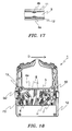
- Fig. 17 is a longitudinal section diagram showing a conventional embankment part.
- the embankment 4a is formed on the lower cover 12 and the embankment 4b is formed on an upper cover 11. Then, because the ink ribbon 3 is drawn out by a control from two sides (i.e. along a vertical direction in Fig. 17 ) through the embankment 4a and the embankment 4b, so the ink ribbon 3 dose not overlap and does not dash out. (e.g. refer to patent document 1).
- Patent document 1 Japan utility model publication H05-035327 .
- Fig. 18 is a diagram showing operation of a conventional ink ribbon cassette. As shown by Fig. 18 , in the case to extend the length of the ink ribbon 3, such state happened, that is, the ink ribbon 3 can not be arranged to be lodged, then the ink ribbon 3 falls into disorder as shown by a broken line part H, and the back part of the ink ribbon 3 outstrips the front part of the ink ribbon 3 as shown by a broken line part F2.
- An ink ribbon cassette comprising an ink ribbon lodging section that has a first cover and an second cover and lodges ink ribbon in a folded state; and a driving means to take the ink ribbon into the ink ribbon lodging section, wherein the ink ribbon is taken into from an enter opening of the ink ribbon lodging section and is drawn out from an ejecting opening of the ink ribbon lodging section through the driving means; and an embankment is furnished near to the ejecting opening of the ink ribbon lodging section and has a transverse width that becomes more and more wide towards movement downstream side of the ink ribbon.
- the embankment may extend from the first cover to the second cover.
- an ink ribbon cassette comprising an ink ribbon lodging section that has a first cover and an second cover and lodges ink ribbon in a folded state; and a driving means to take the ink ribbon into the ink ribbon lodging section, wherein the ink ribbon is taken into from an enter opening of the ink ribbon lodging section and is drawn out from an ejecting opening of the ink ribbon lodging section through the driving means; and a dual embankment is furnished on an ink ribbon movement path placed the outside of the ejecting opening of the ink ribbon lodging section, the dual embankment having a rib shape protruding toward an inside direction, at least at either side of the first cover and the second cover.
- an ink ribbon cassette comprising an ink ribbon lodging section that has a first cover and an second cover and lodges ink ribbon in a folded state; and a driving means to take the ink ribbon into the ink ribbon lodging section, wherein the ink ribbon is taken into from an enter opening of the ink ribbon lodging section and is drawn out from an ejecting opening of the ink ribbon lodging section through the driving means; and at least a protruding portion is furnished on sidewall of the ink ribbon lodging section.
- two protruding portions may be respectively furnished near to the entering opening and the ejecting opening of the ink ribbon lodging section.
- a printing apparatus comprising an ink ribbon cassette, wherein the ink ribbon cassette includes an ink ribbon lodging section that has a first cover and an second cover and lodges ink ribbon in a folded state; and a driving means to take the ink ribbon into the ink ribbon lodging section, wherein the ink ribbon is taken into from an enter opening of the ink ribbon lodging section and is drawn out from an ejecting opening of the ink ribbon lodging section through the driving means; and an embankment is furnished near to the ejecting opening of the ink ribbon lodging section and has a transverse width that becomes more and more wide towards movement downstream side of the ink ribbon.
- the embankment may extend from the first cover to the second cover.
- a printing apparatus comprising an ink ribbon cassette, wherein the ink ribbon cassette includes an ink ribbon lodging section that has a first cover and an second cover and lodges ink ribbon in a folded state; and a driving means to take the ink ribbon into the ink ribbon lodging section, wherein the ink ribbon is taken into from an enter opening of the ink ribbon lodging section and is drawn out from an ejecting opening of the ink ribbon lodging section through the driving means; and a dual embankment is furnished on an ink ribbon movement path placed the outside of the ejecting opening of the ink ribbon lodging section, the dual embankment having a rib shape protruding toward an inside direction, at least at either side of the first cover and the second cover.
- a printing apparatus comprising an ink ribbon cassette, wherein the ink ribbon cassette includes an ink ribbon lodging section that has a first cover and an second cover and lodges ink ribbon in a folded state; and a driving means to take the ink ribbon into the ink ribbon lodging section, wherein the ink ribbon is taken into from an enter opening of the ink ribbon lodging section and is drawn out from an ejecting opening of the ink ribbon lodging section through the driving means; and at least a protruding portion is furnished on sidewall of the ink ribbon lodging section.
- two protruding portions may be respectively furnished near to the entering opening and the ejecting opening of the ink ribbon lodging section.
- the ink ribbon cassette and the printing apparatus of the present invention because provided a lengthways embankment near to an ejecting opening of an ink ribbon lodging section, whose transverse width becomes more and more wide towards movement downstream side, even if in the case that the ink ribbon is extended for prolong the life of the ink ribbon cassette, it is possible to prevent the ink ribbon from getting across the lengthways embankment to cause dual movement.
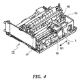
- Fig. 4 is a diagram showing a summary structure of a printing apparatus in embodiment 1 of the present invention
- Fig. 5 is a cubic diagram showing an external view of a printing apparatus in embodiment 1 of the present invention.
- the printing apparatus shown by the Figs. 4 and 5 is that of bottom-pull type, which uses a printing head 18 to performs a print while using a pull up tractor 30 to pull up, for example, sprocket paper 29 serving as medium.
- an ink ribbon cassette 1 is installed as holding the printing head 18.
- a platen 17 and a carriage shaft 14 are installed in parallel.
- the carriage assembly 16 is slidably installed on the carriage shaft 14, and moves while spacing along an arrow B-B1 direction being a shaft direction of the platen 17 through a drive source (not shown) rotates.
- the printing head 18 is driven to correspond to the timing of the spacing operation and is pressed by a ribbon guide 31 as shown Fig. 5 , then performs a print with respect to continuous paper medium such as sprocket paper 29 or the like wrapped round the platen 17.
- sprocket holes 29a are respectively provided along the movement direction of the sprocket paper 29, and fits a post (not shown) furnished on the pull up tractor 30, then moves along an arrow A direction while being fixed.
- Fig. 6 is a diagram showing an installation structure of an ink ribbon cassette of a cartridge assembly in embodiment 1 of the present invention.
- a space motor shaft 24 is installed on a space motor 23, and is connected with a ribbon gear 22 of a ribbon feed gear assembly 21. Then, a power from the space motor 23 is transmitted to a ribbon drive gear 19 via plural gear arrangements 20a ⁇ 20e, and the ribbon drive gear 19 is rotated along an arrow C direction.
- the ribbon drive gear 19 connects with the drive gear 10 of the ink ribbon cassette 1, and takes in the ink ribbon that is lodged in the ink ribbon cassette 1 and is mentioned below through rotating the drive gear 10 along the arrow C direction.
- an ink tank 5 ink is accommodated for providing the ink to the ink ribbon.
- the ink ribbon cassette 1 includes an upper cover 11 as an upper basket body, and a lower cover 12 as a lower basket body so as to form a structure covering circumference.
- a drive method of the ink ribbon cassette 1 because it is not relative to the present invention, its detail explanation is omitted for simplification.
- Fig. 1A is a diagram showing a structure of an ink ribbon cassette in embodiment 1 of the present invention and showing a state in that an upper cover is removed; and Fig. 1B is a diagram showing a side of an ink ribbon cassette in embodiment 1 of the present invention.
- the ink ribbon cassette 1 shown by Fig. 1A is installed in the printing apparatus 15, its upper cover and its lower cover are formed by the upper cover 11 and the lower cover 12 shown by Fig. 1B .
- the ink ribbon cassette 1 includes an ink ribbon 3, an ink ribbon lodging section 6 to lodge the ink ribbon 3 in a folded shape, and an ink tank 5 to accommodate ink.
- a drive gear 10 and a transfer gear 7 placed as facing to the drive gear 10 are furnished. Then, the ink ribbon 3 moves along an arrow D direction through the drive gear 10 and the transfer gear 7 sandwich and roll the ink ribbon 3. Further, under the transfer gear 7, a spring 8 is furnished to press the transfer gear 7 against the drive gear 10.
- the ink tank 5 supplies the ink accommodated in the inside to the ink ribbon 3 via a wick 9 and the transfer gear 7.
- an embankment 4a and an embankment 4b mentioned below are furnished for preventing the ink ribbon 3 from dashing out. Further, on the inside surface of side wall on the outside of the lower cover 12, a lengthways embankment 2 is furnished for preventing the ink ribbon 3 from happening dual movement (i.e. multiple feeding/dual feeding).
- Fig. 2A is an enlarged diagram showing a detail structure of a lengthways embankment part in embodiment 1 of the present invention
- Fig. 2B is a longitudinal section diagram showing a detail structure of a lengthways embankment part in embodiment 1 of the present invention.
- the lengthways embankment 2 is furnished on the lower side wall of cover near to the ejecting opening of the ink ribbon lodging section 6 so as to make an interval making the ink ribbon 3 pass become more and more narrow towards movement downstream side of the ink ribbon 3 and to uniformly extend from the embankment 4a of the lower cover 12 to the embankment 4b of the upper cover 11.
- the shape of the lengthways embankment 2 it may be set into that capable of making the ink ribbon 3 pass become more and more narrow towards movement downstream side of the ink ribbon 3, it also may be set into that of convex type or the like.
- Fig. 3 is a longitudinal section diagram showing a circumference of a guide section in embodiment 1 of the present invention.
- the ink ribbon cassette and the printing apparatus of the embodiment 1 performs the following operation. Next is to explain the operation by using Figs. 7 ⁇ 9 .
- Fig. 7 is a first diagram showing operation of an ink ribbon cassette in embodiment 1 of the present invention
- Fig. 8 is a second diagram showing operation of an ink ribbon cassette in embodiment 1 of the present invention
- Fig. 9 is a third diagram showing operation of an ink ribbon cassette in embodiment 1 of the present invention.
- the ink ribbon 3 is nipped by the drive gear 10 and the transfer gear 7, and is taken into the ink ribbon lodging section 6. Then the ink ribbon 3 is lodged into the ink ribbon lodging section 6 in a folded state.
- space E happens and force acts on the ink ribbon 3 to push out the ink ribbon 3 toward the ejecting opening, as shown by a broken line part F in Fig. 8 , the back part of the ink ribbon 3 outstrips the front part of the ink ribbon 3 and enters the space E, in such a state, the ink ribbon 3 is conveyed to the ejecting opening.
- the lower cover 12 and a guide section 13 makes the width of the ink ribbon movement path 25 become narrow so that the ink ribbon 3 is pressed from upside and underside in an arc shape by the embankment 4a and the embankment 4b and only the ink ribbon 3 can passes, it is possible to more prevent the ink ribbon 3 from happening dual movement.
- the ink ribbon cassette and the printing apparatus in the embodiment 1 because provided a lengthways embankment near to the an ejecting opening of an ink ribbon lodging section, whose transverse width becomes more and more wide towards movement downstream side, even if in the case that the ink ribbon is extended for prolong the life of the ink ribbon cassette, it is possible to prevent the ink ribbon from getting across the lengthways embankment to cause dual movement.
- Fig. 10 is a diagram showing a structure of an ink ribbon cassette in embodiment 2 of the present invention.
- an ink ribbon cassette and a printing apparatus of the embodiment 2 respectively have a dual embankment 26a and a dual embankment 26b that are furnished on the ink ribbon movement path 25 of downstream side of an ink ribbon lodging section 6.
- Fig. 11 is a longitudinal section diagram showing a dual embankment part in embodiment 1 of the present invention.
- the dual embankment 26b and the dual embankment 26a are respectively furnished on the upper cover 11 and the lower cover 12 in a protruding state, the shape of the dual embankment 26a or the dual embankment 26b is a rib shape.
- the ink ribbon 3 to pass between the dual embankment 26a and the dual embankment 26b expands along a transverse direction of the ink ribbon movement path 25, even if the ink ribbon 3 happened dual movement, it is possible to prevent the foreside of the ink ribbon 3 from passing between the dual embankment 26a and the dual embankment 26b.
- the height of the dual embankment 26a and the dual embankment 26b is higher than that of the embankment 4a and the embankment 4b, it is possible to certainly prevent an actual dual movement.
- other compositions because they are the same as that in embodiment 1, their explanations are omitted for simplification.
- the ink ribbon cassette and the printing apparatus of the embodiment 2 performs the following operation. Next is to explain the operation by using Figs. 12 .
- Fig. 12 is a diagram showing operation of an ink ribbon cassette in embodiment 2 of the present invention.
- the ink ribbon 3 is nipped by the drive gear 10 and the transfer gear 7, and is taken into the ink ribbon lodging section 6, then the ink ribbon 3 is lodged into the ink ribbon lodging section 6 in a folded state.
- the height of the dual embankment 26a and the dual embankment 26b is higher than that of the embankment 4a and the embankment 4b shown by Fig. 14 , it is possible to certainly prevent an actual dual movement. Moreover, because the ink ribbon 3 is little near to the dual embankment 26a and the dual embankment 26b, the dual embankment 26a and the dual embankment 26b would not become a movement load of the ink ribbon 3.
- the ink ribbon cassette and the printing apparatus in the embodiment 2 because provided dual embankments on ink ribbon movement path on the downstream side of the ink ribbon lodging section, as respectively protruding from the lower cover and the upper cover, similarly to the embodiment 1, even if in the case that the ink ribbon is extended for prolong the life of the ink ribbon cassette, it is possible to prevent the ink ribbon from getting across the lengthways embankment to cause dual movement.
- Fig. 13 is a diagram showing a structure of an ink ribbon cassette in embodiment 3 of the present invention.
- an ink ribbon cassette and a printing apparatus of the embodiment 3 respectively have a protruding portion 27a serving as a first protruding portion and a protruding portion 27b serving as a second protruding portion, that are provided in the ink ribbon lodging section 6.
- the protruding portion 27a and the protruding portion 27b respectively are a part of the lower cover 12, and respectively are furnished near to entering opening and the ejecting opening of the ink ribbon lodging section 6.
- the protruding portion 27a makes the ink ribbon 3 be pressed and contact with it along its shape; the protruding portion 27b has a weaker embankment action to lighten the density of the ink ribbon 3 pressed into the ejecting opening of the ink ribbon lodging section 6. Then, in order to easily lead the ink ribbon 3 to the ejecting opening of the ink ribbon lodging section 6, as shown by Fig. 13 , it is better to furnish a bending portion 28.
- the ink ribbon cassette and the printing apparatus of the embodiment 3 performs the following operation. Next is to explain the operation by using Figs. 14 .
- Fig. 14 is a diagram showing operation of an ink ribbon cassette in embodiment 3 of the present invention
- the ink ribbon 3 is nipped by the drive gear 10 and the transfer gear 7, and is taken into the ink ribbon lodging section 6, then the ink ribbon 3 is lodged into the ink ribbon lodging section 6 in a folded state.
- the ink ribbon 3 is pressed along an arrow K direction on the opposite side of the protruding portion 27a, the ink ribbon 3 contacts with a position shown by a broken line part J, and does not exist to further enter.
- the ink ribbon 3 is sequentially lodged into the ink ribbon lodging section 6, so it becomes little that the back part of the ink ribbon 3 outstrips the front part of the ink ribbon 3 and is folded.
- the protruding portion 27b has a weaker embankment action to lighten the density of the ink ribbon 3 pressed into a position of a broken line part L, so the ink ribbon 3 smoothly moves to the ejecting opening of the ink ribbon lodging section 6 through the bending portion 28.
- the density of the ink ribbon 3 is adjusted toward the side of the embankment 4a and the embankment 4b from the side of the drive gear 10, the density of the ink ribbon 3 does not become high in circumference of the embankment 4a and the embankment 4b. Therefore, it is possible to reduce friction while drawing out the ink ribbon 3.
- Fig. 15 is a diagram showing a structure of a lower cover in embodiment 3 of the present invention.
- a rib 32 in the ink ribbon lodging section 6 it is possible to furnish a rib 32 in the ink ribbon lodging section 6, and to furnish the protruding portion 27a and the protruding portion 27b on the rib 32 respectively near to the entering opening and the ejecting opening of the ink ribbon lodging section 6.
- the ink ribbon cassette and the printing apparatus in the embodiment 3 because provided the first protruding portion in the space near to the entering opening of the ink ribbon lodging section, it becomes little that the back part of the ink ribbon 3 outstrips the front part of the ink ribbon 3 to be folded. Furthermore, because provided the second protruding portion near to the ejecting opening of the ink ribbon lodging section, it is possible to inhibit the density of the ink ribbon near to the ejecting opening of the ink ribbon lodging section so as to reduce friction while drawing out the ink ribbon. As a result, even if in the case that the ink ribbon is extended for prolong the life of the ink ribbon cassette, it is possible to prevent the ink ribbon from getting across the lengthways embankment to cause dual movement.
Landscapes
- Impression-Transfer Materials And Handling Thereof (AREA)
Abstract

Description
- The invention relates to an ink ribbon cassette to lodge ink ribbon and relates to a printing apparatus.
- Initially, it is to explain a conventional ink ribbon cassette by using
Fig. 16. Fig. 16 is a diagram showing a structure of a conventional ink ribbon cassette. - As shown by
Fig. 16 , in anink ribbon cassette 1, anink ribbon 3 is sandwiched and is taken into an inkribbon lodging section 6 by rotation of adrive gear 10 and atransfer gear 7; theink ribbon 3, while guided by anembankment 4a formed onlower cover 12 and anembankment 4b that will be mentioned below, is drawn out from the inkribbon lodging section 6 as a strip of ink ribbon. -
Fig. 17 is a longitudinal section diagram showing a conventional embankment part. - As shown by
Fig. 17 , theembankment 4a is formed on thelower cover 12 and theembankment 4b is formed on anupper cover 11. Then, because theink ribbon 3 is drawn out by a control from two sides (i.e. along a vertical direction inFig. 17 ) through theembankment 4a and theembankment 4b, so theink ribbon 3 dose not overlap and does not dash out. (e.g. refer to patent document 1).
Patent document 1: Japan utility model publicationH05-035327 - However, in order to prolong the life of the
ink ribbon cassette 1, it is necessary to extend the length of theink ribbon 3. -
Fig. 18 is a diagram showing operation of a conventional ink ribbon cassette. As shown byFig. 18 , in the case to extend the length of theink ribbon 3, such state happened, that is, theink ribbon 3 can not be arranged to be lodged, then theink ribbon 3 falls into disorder as shown by a broken line part H, and the back part of theink ribbon 3 outstrips the front part of theink ribbon 3 as shown by a broken line part F2. - In such state, there is the following problem. That is, in the conventional
ink ribbon cassette 1, though theink ribbon 3 does not dashes out by theembankment 4a and theembankment 4b, the front and the back parts of theink ribbon 3 are synchronously drawn out because of a friction caused when theink ribbon 3 is drawn out, then theink ribbon 3 gets across theembankment 4a and theembankment 4b as shown by a broken line part G2, theink ribbon 3 happens a dual movement so that a ribbon jam happened. - It is, therefore, an object of the invention to provide an ink ribbon cassette and a printing apparatus capable of solving the above problem.
- According to the present invention, there is provided An ink ribbon cassette, comprising an ink ribbon lodging section that has a first cover and an second cover and lodges ink ribbon in a folded state; and a driving means to take the ink ribbon into the ink ribbon lodging section, wherein the ink ribbon is taken into from an enter opening of the ink ribbon lodging section and is drawn out from an ejecting opening of the ink ribbon lodging section through the driving means; and an embankment is furnished near to the ejecting opening of the ink ribbon lodging section and has a transverse width that becomes more and more wide towards movement downstream side of the ink ribbon.
- Moreover, in the ink ribbon cassette, the embankment may extend from the first cover to the second cover.
- Moreover, according to the present invention, there is also provided an ink ribbon cassette, comprising an ink ribbon lodging section that has a first cover and an second cover and lodges ink ribbon in a folded state; and a driving means to take the ink ribbon into the ink ribbon lodging section, wherein the ink ribbon is taken into from an enter opening of the ink ribbon lodging section and is drawn out from an ejecting opening of the ink ribbon lodging section through the driving means; and a dual embankment is furnished on an ink ribbon movement path placed the outside of the ejecting opening of the ink ribbon lodging section, the dual embankment having a rib shape protruding toward an inside direction, at least at either side of the first cover and the second cover.
- Moreover, according to the present invention, there is also provided an ink ribbon cassette, comprising an ink ribbon lodging section that has a first cover and an second cover and lodges ink ribbon in a folded state; and a driving means to take the ink ribbon into the ink ribbon lodging section, wherein the ink ribbon is taken into from an enter opening of the ink ribbon lodging section and is drawn out from an ejecting opening of the ink ribbon lodging section through the driving means; and at least a protruding portion is furnished on sidewall of the ink ribbon lodging section.
- Moreover, in the ink ribbon cassette, two protruding portions may be respectively furnished near to the entering opening and the ejecting opening of the ink ribbon lodging section.
- Further, according to the present invention, there is provided a printing apparatus, comprising an ink ribbon cassette, wherein the ink ribbon cassette includes an ink ribbon lodging section that has a first cover and an second cover and lodges ink ribbon in a folded state; and a driving means to take the ink ribbon into the ink ribbon lodging section, wherein the ink ribbon is taken into from an enter opening of the ink ribbon lodging section and is drawn out from an ejecting opening of the ink ribbon lodging section through the driving means; and an embankment is furnished near to the ejecting opening of the ink ribbon lodging section and has a transverse width that becomes more and more wide towards movement downstream side of the ink ribbon.
- Moreover, in the printing apparatus ink ribbon cassette, the embankment may extend from the first cover to the second cover.
- Moreover, according to the present invention, there is also provided a printing apparatus, comprising an ink ribbon cassette, wherein the ink ribbon cassette includes an ink ribbon lodging section that has a first cover and an second cover and lodges ink ribbon in a folded state; and a driving means to take the ink ribbon into the ink ribbon lodging section, wherein the ink ribbon is taken into from an enter opening of the ink ribbon lodging section and is drawn out from an ejecting opening of the ink ribbon lodging section through the driving means; and a dual embankment is furnished on an ink ribbon movement path placed the outside of the ejecting opening of the ink ribbon lodging section, the dual embankment having a rib shape protruding toward an inside direction, at least at either side of the first cover and the second cover.
- Moreover, according to the present invention, there is also provided a printing apparatus, comprising an ink ribbon cassette, wherein the ink ribbon cassette includes an ink ribbon lodging section that has a first cover and an second cover and lodges ink ribbon in a folded state; and a driving means to take the ink ribbon into the ink ribbon lodging section, wherein the ink ribbon is taken into from an enter opening of the ink ribbon lodging section and is drawn out from an ejecting opening of the ink ribbon lodging section through the driving means; and at least a protruding portion is furnished on sidewall of the ink ribbon lodging section.
- Moreover, in the printing apparatus, two protruding portions may be respectively furnished near to the entering opening and the ejecting opening of the ink ribbon lodging section.
- According to the ink ribbon cassette and the printing apparatus of the present invention, because provided a lengthways embankment near to an ejecting opening of an ink ribbon lodging section, whose transverse width becomes more and more wide towards movement downstream side, even if in the case that the ink ribbon is extended for prolong the life of the ink ribbon cassette, it is possible to prevent the ink ribbon from getting across the lengthways embankment to cause dual movement.
- The above and other objects and features of the present invention will become apparent from the following detailed description and the appended claims with reference to the accompanying drawings.
-
-
Fig. 1A is a diagram showing a structure of an ink ribbon cassette inembodiment 1 of the present invention and showing a state in that an upper cover is removed; -
Fig. 1B is a diagram showing a side of an ink ribbon cassette inembodiment 1 of the present invention; -
Fig. 2A is an enlarged diagram showing a detail structure of a lengthways embankment part inembodiment 1 of the present invention; -
Fig. 2B is a longitudinal section diagram showing a detail structure of a lengthways embankment part inembodiment 1 of the present invention; -
Fig. 3 is a longitudinal section diagram showing a circumference of a guide section inembodiment 1 of the present invention; -
Fig. 4 is a diagram showing a summary structure of a printing apparatus inembodiment 1 of the present invention; -
Fig. 5 is a cubic diagram showing an external view of a printing apparatus inembodiment 1 of the present invention; -
Fig. 6 is a diagram showing an installation structure of an ink ribbon cassette of a cartridge assembly inembodiment 1 of the present invention; -
Fig. 7 is a first diagram showing operation of an ink ribbon cassette inembodiment 1 of the present invention; -
Fig. 8 is a second diagram showing operation of an ink ribbon cassette inembodiment 1 of the present invention; -
Fig. 9 is a third diagram showing operation of an ink ribbon cassette inembodiment 1 of the present invention; -
Fig. 10 is a diagram showing a structure of an ink ribbon cassette inembodiment 2 of the present invention; -
Fig. 11 is a longitudinal section diagram showing a dual embankment part inembodiment 1 of the present invention; -
Fig. 12 is a diagram showing operation of an ink ribbon cassette inembodiment 2 of the present invention; -
Fig. 13 is a diagram showing a structure of an ink ribbon cassette inembodiment 3 of the present invention; -
Fig. 14 is a diagram showing operation of an ink ribbon cassette inembodiment 3 of the present invention; -
Fig. 15 is a diagram showing a structure of a lower cover inembodiment 3 of the present invention; -
Fig. 16 is a diagram showing a structure of a conventional ink ribbon cassette; -
Fig. 17 is a longitudinal section diagram showing a conventional embankment part; and -
Fig. 18 is a diagram showing operation of a conventional ink ribbon cassette. - Embodiments of the invention will be described in detail hereinbelow with reference to the drawings. In the following embodiments, regarding the same element used in common, the same symbol is assigned.
- Initially, it is to explain a structure and an external view of a
printing apparatus 15 installing anink ribbon cassette 1 ofembodiment 1. -
Fig. 4 is a diagram showing a summary structure of a printing apparatus inembodiment 1 of the present invention; andFig. 5 is a cubic diagram showing an external view of a printing apparatus inembodiment 1 of the present invention. - The printing apparatus shown by the
Figs. 4 and5 is that of bottom-pull type, which uses aprinting head 18 to performs a print while using a pull uptractor 30 to pull up, for example,sprocket paper 29 serving as medium. - As shown by
Fig. 4 , in acarriage assembly 16, anink ribbon cassette 1 is installed as holding theprinting head 18. Aplaten 17 and acarriage shaft 14 are installed in parallel. Thecarriage assembly 16 is slidably installed on thecarriage shaft 14, and moves while spacing along an arrow B-B1 direction being a shaft direction of theplaten 17 through a drive source (not shown) rotates. - The
printing head 18 is driven to correspond to the timing of the spacing operation and is pressed by aribbon guide 31 as shownFig. 5 , then performs a print with respect to continuous paper medium such assprocket paper 29 or the like wrapped round theplaten 17. - Moreover, on both sides of the
sprocket paper 29,sprocket holes 29a are respectively provided along the movement direction of thesprocket paper 29, and fits a post (not shown) furnished on the pull uptractor 30, then moves along an arrow A direction while being fixed. - That is, there is such a structure: the
carriage assembly 16 installing theprinting head 18 and theink ribbon cassette 1, while sliding thecarriage shaft 14 furnished in parallel with theplaten 17, spaces theprinting head 18 along the arrow B-B1 direction. To correspond to the timing of the operation, plural wires (not shown) provided inside theink ribbon cassette 1 are driven along the arrow A direction, and impacted via ink ribbon (not shown) lodged in theink ribbon cassette 1, then a print is performed with respect to thesprocket paper 29. -
Fig. 6 is a diagram showing an installation structure of an ink ribbon cassette of a cartridge assembly inembodiment 1 of the present invention. - A
space motor shaft 24 is installed on aspace motor 23, and is connected with a ribbon gear 22 of a ribbonfeed gear assembly 21. Then, a power from thespace motor 23 is transmitted to aribbon drive gear 19 viaplural gear arrangements 20a~20e, and theribbon drive gear 19 is rotated along an arrow C direction. - The
ribbon drive gear 19 connects with thedrive gear 10 of theink ribbon cassette 1, and takes in the ink ribbon that is lodged in theink ribbon cassette 1 and is mentioned below through rotating thedrive gear 10 along the arrow C direction. In anink tank 5, ink is accommodated for providing the ink to the ink ribbon. Then, theink ribbon cassette 1 includes anupper cover 11 as an upper basket body, and alower cover 12 as a lower basket body so as to form a structure covering circumference. Moreover, regarding a drive method of theink ribbon cassette 1, because it is not relative to the present invention, its detail explanation is omitted for simplification. -
Fig. 1A is a diagram showing a structure of an ink ribbon cassette inembodiment 1 of the present invention and showing a state in that an upper cover is removed; andFig. 1B is a diagram showing a side of an ink ribbon cassette inembodiment 1 of the present invention. - The
ink ribbon cassette 1 shown byFig. 1A is installed in theprinting apparatus 15, its upper cover and its lower cover are formed by theupper cover 11 and thelower cover 12 shown byFig. 1B . - The
ink ribbon cassette 1 includes anink ribbon 3, an inkribbon lodging section 6 to lodge theink ribbon 3 in a folded shape, and anink tank 5 to accommodate ink. - Near by the entering opening, a
drive gear 10 and atransfer gear 7 placed as facing to thedrive gear 10 are furnished. Then, theink ribbon 3 moves along an arrow D direction through thedrive gear 10 and thetransfer gear 7 sandwich and roll theink ribbon 3. Further, under thetransfer gear 7, aspring 8 is furnished to press thetransfer gear 7 against thedrive gear 10. - The
ink tank 5 supplies the ink accommodated in the inside to theink ribbon 3 via awick 9 and thetransfer gear 7. - Near by the ejecting opening of the ink
ribbon lodging section 6, anembankment 4a and anembankment 4b mentioned below are furnished for preventing theink ribbon 3 from dashing out. Further, on the inside surface of side wall on the outside of thelower cover 12, alengthways embankment 2 is furnished for preventing theink ribbon 3 from happening dual movement (i.e. multiple feeding/dual feeding). -
Fig. 2A is an enlarged diagram showing a detail structure of a lengthways embankment part inembodiment 1 of the present invention; andFig. 2B is a longitudinal section diagram showing a detail structure of a lengthways embankment part inembodiment 1 of the present invention. - The
lengthways embankment 2 is furnished on the lower side wall of cover near to the ejecting opening of the inkribbon lodging section 6 so as to make an interval making theink ribbon 3 pass become more and more narrow towards movement downstream side of theink ribbon 3 and to uniformly extend from theembankment 4a of thelower cover 12 to theembankment 4b of theupper cover 11. - Moreover, regarding the shape of the
lengthways embankment 2, it may be set into that capable of making theink ribbon 3 pass become more and more narrow towards movement downstream side of theink ribbon 3, it also may be set into that of convex type or the like. -
Fig. 3 is a longitudinal section diagram showing a circumference of a guide section inembodiment 1 of the present invention. - As shown by
Fig. 3 , because the inside surface of the side wall of thelower cover 12 and aguide section 13 makes the width of an inkribbon movement path 25 become narrow, that is, the width makes theink ribbon 3 be pressed from upside and underside in an arc shape by theembankment 4a and theembankment 4b so that only theink ribbon 3 passes, even if the back part of theink ribbon 3 outstrips the front part of theink ribbon 3, it is possible to prevent the back part of theink ribbon 3 from entering. - According to the above-stated structure, the ink ribbon cassette and the printing apparatus of the
embodiment 1 performs the following operation. Next is to explain the operation by usingFigs. 7~9 . -
Fig. 7 is a first diagram showing operation of an ink ribbon cassette inembodiment 1 of the present invention;Fig. 8 is a second diagram showing operation of an ink ribbon cassette inembodiment 1 of the present invention;Fig. 9 is a third diagram showing operation of an ink ribbon cassette inembodiment 1 of the present invention. - Initially, as shown by
Fig. 7 , theink ribbon 3 is nipped by thedrive gear 10 and thetransfer gear 7, and is taken into the inkribbon lodging section 6. Then theink ribbon 3 is lodged into the inkribbon lodging section 6 in a folded state. - However, in the ink
ribbon lodging section 6, space E happens and force acts on theink ribbon 3 to push out theink ribbon 3 toward the ejecting opening, as shown by a broken line part F inFig. 8 , the back part of theink ribbon 3 outstrips the front part of theink ribbon 3 and enters the space E, in such a state, theink ribbon 3 is conveyed to the ejecting opening. - At that time, though the
ink ribbon 3 shown by the broken line part F and conveyed to the ejecting opening has a tendency to be drawn out in company with the front part of theink ribbon 3 that has drawn out due to a friction between the front and the back parts, as shown by a broken line part G inFig. 9 , because the foreside of the back part of theink ribbon 3 comes into contact with thelengthways embankment 2, and theink ribbon 3 is not caught since the inclination of thelengthways embankment 2, theink ribbon 3 does not get over theembankment 4a and theembankment 4b so that there is no dual movement. - Further, because the
lower cover 12 and aguide section 13 makes the width of the inkribbon movement path 25 become narrow so that theink ribbon 3 is pressed from upside and underside in an arc shape by theembankment 4a and theembankment 4b and only theink ribbon 3 can passes, it is possible to more prevent theink ribbon 3 from happening dual movement. - As stated in detail above, according to the ink ribbon cassette and the printing apparatus in the
embodiment 1, because provided a lengthways embankment near to the an ejecting opening of an ink ribbon lodging section, whose transverse width becomes more and more wide towards movement downstream side, even if in the case that the ink ribbon is extended for prolong the life of the ink ribbon cassette, it is possible to prevent the ink ribbon from getting across the lengthways embankment to cause dual movement. -
Fig. 10 is a diagram showing a structure of an ink ribbon cassette inembodiment 2 of the present invention. - As shown by
Fig. 10 , an ink ribbon cassette and a printing apparatus of theembodiment 2 respectively have adual embankment 26a and adual embankment 26b that are furnished on the inkribbon movement path 25 of downstream side of an inkribbon lodging section 6. -
Fig. 11 is a longitudinal section diagram showing a dual embankment part inembodiment 1 of the present invention. - The
dual embankment 26b and thedual embankment 26a are respectively furnished on theupper cover 11 and thelower cover 12 in a protruding state, the shape of thedual embankment 26a or thedual embankment 26b is a rib shape. - Because the
ink ribbon 3 to pass between thedual embankment 26a and thedual embankment 26b expands along a transverse direction of the inkribbon movement path 25, even if theink ribbon 3 happened dual movement, it is possible to prevent the foreside of theink ribbon 3 from passing between thedual embankment 26a and thedual embankment 26b. - Further, because the height of the
dual embankment 26a and thedual embankment 26b is higher than that of theembankment 4a and theembankment 4b, it is possible to certainly prevent an actual dual movement. Regarding other compositions, because they are the same as that inembodiment 1, their explanations are omitted for simplification. - According to the above-stated structure, the ink ribbon cassette and the printing apparatus of the
embodiment 2 performs the following operation. Next is to explain the operation by usingFigs. 12 . -
Fig. 12 is a diagram showing operation of an ink ribbon cassette inembodiment 2 of the present invention. - It is the same as the
embodiment 1 that theink ribbon 3 is nipped by thedrive gear 10 and thetransfer gear 7, and is taken into the inkribbon lodging section 6, then theink ribbon 3 is lodged into the inkribbon lodging section 6 in a folded state. - Further, as shown by a broken line part F1 on the left side of the
ink ribbon 3 inFig. 12 , when the back part of theink ribbon 3 which has outstripped the front part of theink ribbon 3 comes, because of a friction between the front part and the back part, the back part of theink ribbon 3 gets over theembankment 4a and theembankment 4b and is drawn out in company with the front part of theink ribbon 3. - When the foreside of the
ink ribbon 3 having happened dual movement comes to a position shown by a broken line part G1, the foreside of theink ribbon 3 having happening dual movement hits thedual embankment 26a and thedual embankment 26b expanding along a lengthways direction of the inkribbon movement path 25, and is stopped to get across thedual embankment 26a and thedual embankment 26b. - Further, because the height of the
dual embankment 26a and thedual embankment 26b is higher than that of theembankment 4a and theembankment 4b shown byFig. 14 , it is possible to certainly prevent an actual dual movement. Moreover, because theink ribbon 3 is little near to thedual embankment 26a and thedual embankment 26b, thedual embankment 26a and thedual embankment 26b would not become a movement load of theink ribbon 3. - Furthermore, in the description stated above, though only explained to provide the
dual embankment 26a and thedual embankment 26b, it is possible to only provide either of thedual embankment 26a and thedual embankment 26b. - As stated in detail above, according to the ink ribbon cassette and the printing apparatus in the
embodiment 2, because provided dual embankments on ink ribbon movement path on the downstream side of the ink ribbon lodging section, as respectively protruding from the lower cover and the upper cover, similarly to theembodiment 1, even if in the case that the ink ribbon is extended for prolong the life of the ink ribbon cassette, it is possible to prevent the ink ribbon from getting across the lengthways embankment to cause dual movement. -
Fig. 13 is a diagram showing a structure of an ink ribbon cassette inembodiment 3 of the present invention. - As shown by
Fig. 13 , an ink ribbon cassette and a printing apparatus of theembodiment 3 respectively have a protrudingportion 27a serving as a first protruding portion and a protrudingportion 27b serving as a second protruding portion, that are provided in the inkribbon lodging section 6. The protrudingportion 27a and the protrudingportion 27b respectively are a part of thelower cover 12, and respectively are furnished near to entering opening and the ejecting opening of the inkribbon lodging section 6. - The protruding
portion 27a makes theink ribbon 3 be pressed and contact with it along its shape; the protrudingportion 27b has a weaker embankment action to lighten the density of theink ribbon 3 pressed into the ejecting opening of the inkribbon lodging section 6. Then, in order to easily lead theink ribbon 3 to the ejecting opening of the inkribbon lodging section 6, as shown byFig. 13 , it is better to furnish a bendingportion 28. - Regarding other compositions, because they are the same as that in
embodiments - According to the above-stated structure, the ink ribbon cassette and the printing apparatus of the
embodiment 3 performs the following operation. Next is to explain the operation by usingFigs. 14 . -
Fig. 14 is a diagram showing operation of an ink ribbon cassette inembodiment 3 of the present invention - It is the same as the
embodiments ink ribbon 3 is nipped by thedrive gear 10 and thetransfer gear 7, and is taken into the inkribbon lodging section 6, then theink ribbon 3 is lodged into the inkribbon lodging section 6 in a folded state. - When the
ink ribbon 3 is taken into the space E of the inkribbon lodging section 6 by thedrive gear 10, as shown byFig. 14 , because theink ribbon 3 is pressed along the shape of the protrudingportion 27a and contacts with the protrudingportion 27a in a position shown by a broken line part I, theink ribbon 3 does not exist to further enter the space E. - Further, because the
ink ribbon 3 is pressed along an arrow K direction on the opposite side of the protrudingportion 27a, theink ribbon 3 contacts with a position shown by a broken line part J, and does not exist to further enter. Thus, theink ribbon 3 is sequentially lodged into the inkribbon lodging section 6, so it becomes little that the back part of theink ribbon 3 outstrips the front part of theink ribbon 3 and is folded. - Furthermore, the protruding
portion 27b has a weaker embankment action to lighten the density of theink ribbon 3 pressed into a position of a broken line part L, so theink ribbon 3 smoothly moves to the ejecting opening of the inkribbon lodging section 6 through the bendingportion 28. - According to the structure stated above, because the density of the
ink ribbon 3 is adjusted toward the side of theembankment 4a and theembankment 4b from the side of thedrive gear 10, the density of theink ribbon 3 does not become high in circumference of theembankment 4a and theembankment 4b. Therefore, it is possible to reduce friction while drawing out theink ribbon 3. - Moreover, in the description stated above, though only explained to provide the protruding
portion 27a and the protrudingportion 27b, i.e. two protruding portions, it is possible to provide more protruding portions or only one protruding portion. -
Fig. 15 is a diagram showing a structure of a lower cover inembodiment 3 of the present invention. - As shown by
Fig. 15 , it is possible to furnish arib 32 in the inkribbon lodging section 6, and to furnish the protrudingportion 27a and the protrudingportion 27b on therib 32 respectively near to the entering opening and the ejecting opening of the inkribbon lodging section 6. - As stated in detail above, according to the ink ribbon cassette and the printing apparatus in the
embodiment 3, because provided the first protruding portion in the space near to the entering opening of the ink ribbon lodging section, it becomes little that the back part of theink ribbon 3 outstrips the front part of theink ribbon 3 to be folded. Furthermore, because provided the second protruding portion near to the ejecting opening of the ink ribbon lodging section, it is possible to inhibit the density of the ink ribbon near to the ejecting opening of the ink ribbon lodging section so as to reduce friction while drawing out the ink ribbon. As a result, even if in the case that the ink ribbon is extended for prolong the life of the ink ribbon cassette, it is possible to prevent the ink ribbon from getting across the lengthways embankment to cause dual movement. - In the
embodiments portion 28 is not furnished in the inkribbon lodging section 6. However, the bendingportion 28 may be furnished as theembodiment 3. Thus, it is possible to further smoothly move theink ribbon 3 to the ejecting opening of the inkribbon lodging section 6. The utilization possibility in industry: - Not only the present invention can be applied to the above stated case, but also the present invention can be applied to various printing apparatus using the ink ribbon cassette.
- The present invention is not limited to the foregoing embodiments but many modifications and variations are possible within the spirit and scope of the appended claims of the invention.
Claims (10)
- An ink ribbon cassette, comprising:an ink ribbon lodging section that has a first cover and an second cover and lodges ink ribbon in a folded state; anda driving means to take the ink ribbon into the ink ribbon lodging section,wherein the ink ribbon is taken into from an enter opening of the ink ribbon lodging section and is drawn out from an ejecting opening of the ink ribbon lodging section through the driving means; and an embankment is furnished near to the ejecting opening of the ink ribbon lodging section and has a transverse width that becomes more and more wide towards movement downstream side of the ink ribbon.
- The ink ribbon cassette according to claim 1,
wherein the embankment extends from the first cover to the second cover. - An ink ribbon cassette, comprising:an ink ribbon lodging section that has a first cover and an second cover and lodges ink ribbon in a folded state; anda driving means to take the ink ribbon into the ink ribbon lodging section,wherein the ink ribbon is taken into from an enter opening of the ink ribbon lodging section and is drawn out from an ejecting opening of the ink ribbon lodging section through the driving means; and a dual embankment is furnished on an ink ribbon movement path placed the outside of the ejecting opening of the ink ribbon lodging section, the dual embankment having a rib shape protruding toward an inside direction, at least at either side of the first cover and the second cover.
- An ink ribbon cassette, comprising:an ink ribbon lodging section that has a first cover and an second cover and lodges ink ribbon in a folded state; anda driving means to take the ink ribbon into the ink ribbon lodging section,wherein the ink ribbon is taken into from an enter opening of the ink ribbon lodging section and is drawn out from an ejecting opening of the ink ribbon lodging section through the driving means; and at least a protruding portion is furnished on sidewall of the ink ribbon lodging section.
- The ink ribbon cassette according to claim 4,
wherein two protruding portions are respectively furnished near to the entering opening and the ejecting opening of the ink ribbon lodging section. - A printing apparatus, comprising:an ink ribbon cassette,wherein the ink ribbon cassette includes:an ink ribbon lodging section that has a first cover and an second cover and lodges ink ribbon in a folded state; anda driving means to take the ink ribbon into the ink ribbon lodging section,wherein the ink ribbon is taken into from an enter opening of the ink ribbon lodging section and is drawn out from an ejecting opening of the ink ribbon lodging section through the driving means; and an embankment is furnished near to the ejecting opening of the ink ribbon lodging section and has a transverse width that becomes more and more wide towards movement downstream side of the ink ribbon.
- The printing apparatus ink ribbon cassette according to claim 6,
wherein the embankment extends from the first cover to the second cover. - A printing apparatus, comprising:an ink ribbon cassette,wherein the ink ribbon cassette includes:an ink ribbon lodging section that has a first cover and an second cover and lodges ink ribbon in a folded state; anda driving means to take the ink ribbon into the ink ribbon lodging section,wherein the ink ribbon is taken into from an enter opening of the ink ribbon lodging section and is drawn out from an ejecting opening of the ink ribbon lodging section through the driving means; and a dual embankment is furnished on an ink ribbon movement path placed the outside of the ejecting opening of the ink ribbon lodging section, the dual embankment having a rib shape protruding toward an inside direction, at least at either side of the first cover and the second cover.
- A printing apparatus, comprising:an ink ribbon cassette,wherein the ink ribbon cassette includes:an ink ribbon lodging section that has a first cover and an second cover and lodges ink ribbon in a folded state; anda driving means to take the ink ribbon into the ink ribbon lodging section,wherein the ink ribbon is taken into from an enter opening of the ink ribbon lodging section and is drawn out from an ejecting opening of the ink ribbon lodging section through the driving means; and at least a protruding portion is furnished on sidewall of the ink ribbon lodging section.
- The printing apparatus according to claim 9,
wherein two protruding portions are respectively furnished near to the entering opening and the ejecting opening of the ink ribbon lodging section.
Applications Claiming Priority (1)
| Application Number | Priority Date | Filing Date | Title |
|---|---|---|---|
| JP2007071163A JP4440943B2 (en) | 2007-03-19 | 2007-03-19 | Ink ribbon cassette and printing apparatus |
Publications (3)
| Publication Number | Publication Date |
|---|---|
| EP1972458A2 true EP1972458A2 (en) | 2008-09-24 |
| EP1972458A3 EP1972458A3 (en) | 2010-07-07 |
| EP1972458B1 EP1972458B1 (en) | 2011-10-12 |
Family
ID=39557681
Family Applications (1)
| Application Number | Title | Priority Date | Filing Date |
|---|---|---|---|
| EP08101814A Active EP1972458B1 (en) | 2007-03-19 | 2008-02-20 | Ink ribbon cassette and printing apparatus |
Country Status (4)
| Country | Link |
|---|---|
| US (1) | US8770873B2 (en) |
| EP (1) | EP1972458B1 (en) |
| JP (1) | JP4440943B2 (en) |
| CN (1) | CN101269591B (en) |
Families Citing this family (2)
| Publication number | Priority date | Publication date | Assignee | Title |
|---|---|---|---|---|
| JP5945770B2 (en) * | 2012-09-03 | 2016-07-05 | フジコピアン株式会社 | Ink ribbon cassette of printing device |
| JP7146337B2 (en) * | 2019-03-05 | 2022-10-04 | フジコピアン株式会社 | ink ribbon cassette |
Citations (2)
| Publication number | Priority date | Publication date | Assignee | Title |
|---|---|---|---|---|
| JPS5448715U (en) | 1977-09-10 | 1979-04-04 | ||
| US4645364A (en) | 1984-09-26 | 1987-02-24 | Oki Electric Industry Co., Ltd. | Ink ribbon cartridge |
Family Cites Families (27)
| Publication number | Priority date | Publication date | Assignee | Title |
|---|---|---|---|---|
| IT1024841B (en) * | 1974-11-18 | 1978-07-20 | Olivetti Ing C S P A | CARTRIDGE FOR A CONTAINER INKING WITHOUT END OF SORIVENTI OFFICE MACHINES |
| US3993182A (en) * | 1975-10-14 | 1976-11-23 | Trw Inc. | Endless inked ribbon cartridge |
| DE2551677B2 (en) * | 1975-11-18 | 1978-05-18 | Franz Buettner Ag, Egg, Zuerich (Schweiz) | Cassette for writing tape with refill device |
| FR2391078A1 (en) * | 1977-05-17 | 1978-12-15 | Cii Honeywell Bull | INK RIBBON CARTRIDGE FOR PRINTING OR SIMILAR MACHINES |
| DE2740243A1 (en) | 1977-09-07 | 1979-03-15 | Bayer Ag | PROCESS FOR THE PRODUCTION OF DIALKYLCARBONATES |
| IT1159918B (en) * | 1978-10-03 | 1987-03-04 | Honeywell Inf Systems | ENDLESS INKED BELT CARTRIDGE WITH INTERCHANGEABLE REINKING CARTRIDGE |
| JPS5869085A (en) | 1981-10-21 | 1983-04-25 | Brother Ind Ltd | ribbon cassette |
| JPS5892066U (en) * | 1981-12-16 | 1983-06-22 | 株式会社リコー | Printer ribbon cartridge |
| JPS6162057A (en) | 1984-09-04 | 1986-03-29 | Konishiroku Photo Ind Co Ltd | Picture formation method |
| US4830524A (en) * | 1984-11-20 | 1989-05-16 | Typerite Ribbon Manufacturing Corp. | Ribbon cartridge |
| GB8527594D0 (en) * | 1985-11-08 | 1985-12-11 | Data Recording Instr Co | Ribbon cassette for printers |
| GB2184998B (en) * | 1986-01-08 | 1990-03-28 | Canon Kk | Ink ribbon cassette |
| IT1187942B (en) * | 1986-02-28 | 1987-12-23 | Olivetti & Co Spa | CARTRIDGES FOR INKED TAPE WITH REINKING DEVICE |
| US5083878A (en) * | 1988-02-26 | 1992-01-28 | Surti Tyrone N | Ribbon cartridge having integral gear supports |
| US4840503A (en) * | 1988-03-31 | 1989-06-20 | International Business Machine Corporation | Stuffed chamber ribbon cartridge |
| JPH0780337B2 (en) * | 1989-06-23 | 1995-08-30 | 富士通株式会社 | Ribbon cassette and printer using the same |
| JPH0491977A (en) | 1990-08-07 | 1992-03-25 | Oki Electric Ind Co Ltd | Reinking color ribbon cassette and ink ribbon selecting mechanism |
| JPH0490566U (en) * | 1990-12-25 | 1992-08-06 | ||
| JP3424130B2 (en) | 1991-07-30 | 2003-07-07 | 豊田工機株式会社 | Laser processing machine |
| US6422771B1 (en) * | 1992-01-17 | 2002-07-23 | Stenograph Corporation | Disposable ribbon cartridge for shorthand machine |
| JPH0655822A (en) * | 1992-08-06 | 1994-03-01 | Fujicopian Co Ltd | Ink ribbon cassette |
| WO1994022673A1 (en) * | 1993-04-06 | 1994-10-13 | Ayres David W | Disposable ribbon cassette within a reloadable cartridge |
| US5487615A (en) * | 1994-10-28 | 1996-01-30 | Sercomp Corporation | Ribbon drive assembly for ribbon cartridge |
| JPH08174975A (en) * | 1994-12-27 | 1996-07-09 | Fujicopian Co Ltd | Ink ribbon cassette |
| US5746522A (en) * | 1996-12-11 | 1998-05-05 | Ncr Corporation | Liquid tank re-inker using ball transfer mechanism |
| US20080056795A1 (en) * | 2006-08-31 | 2008-03-06 | Toshiba Tec Kabushiki Kaisha | Ribbon cassette and printer using the ribbon cassette |
| JP5448715B2 (en) | 2009-10-22 | 2014-03-19 | キヤノン株式会社 | Imaging apparatus and control method thereof |
-
2007
- 2007-03-19 JP JP2007071163A patent/JP4440943B2/en active Active
-
2008
- 2008-02-20 EP EP08101814A patent/EP1972458B1/en active Active
- 2008-02-27 CN CN200810080968.4A patent/CN101269591B/en active Active
- 2008-02-28 US US12/071,972 patent/US8770873B2/en active Active
Patent Citations (2)
| Publication number | Priority date | Publication date | Assignee | Title |
|---|---|---|---|---|
| JPS5448715U (en) | 1977-09-10 | 1979-04-04 | ||
| US4645364A (en) | 1984-09-26 | 1987-02-24 | Oki Electric Industry Co., Ltd. | Ink ribbon cartridge |
Also Published As
| Publication number | Publication date |
|---|---|
| JP4440943B2 (en) | 2010-03-24 |
| CN101269591B (en) | 2012-06-13 |
| CN101269591A (en) | 2008-09-24 |
| EP1972458B1 (en) | 2011-10-12 |
| US20080232889A1 (en) | 2008-09-25 |
| EP1972458A3 (en) | 2010-07-07 |
| JP2008229973A (en) | 2008-10-02 |
| US8770873B2 (en) | 2014-07-08 |
Similar Documents
| Publication | Publication Date | Title |
|---|---|---|
| US7677548B2 (en) | Cassette and image forming apparatus with multiple separation portions | |
| US20080296831A1 (en) | Cassette and image forming apparatus | |
| US8469617B2 (en) | Printer platen support mechanism and roll paper printer | |
| JP2009083979A (en) | Image recording device | |
| JP2006026931A (en) | Printing device | |
| JP2009083232A (en) | Image recording device | |
| EP3348409B1 (en) | Printer | |
| EP0853003B1 (en) | Printer | |
| US20080232889A1 (en) | Ink ribbon cassette and printing apparatus | |
| EP1803574B1 (en) | Inkjet recording device and driving unit provided therein | |
| US20100230889A1 (en) | Printing apparatus | |
| JP2011110812A (en) | Recording device and recording medium supplying structure for the recording device | |
| US8651757B2 (en) | Printer | |
| CN204222391U (en) | Thermal printer | |
| US20250381784A1 (en) | Printed sheet cutting device for printer | |
| US8020986B2 (en) | Image recording apparatus | |
| JP4265593B2 (en) | Inkjet recording device | |
| US10016994B2 (en) | Recording apparatus | |
| JP2014195903A (en) | Recording device | |
| KR20190074631A (en) | Cutting apparatus for printer paper | |
| EP1270244A1 (en) | Printer | |
| JP3859007B2 (en) | Thermal transfer image forming device | |
| JP2015024605A (en) | Recording device | |
| JP2008100818A (en) | Paper guide mechanism and printer using the same | |
| JP2007118240A (en) | Cable holding mechanism and recording device |
Legal Events
| Date | Code | Title | Description |
|---|---|---|---|
| PUAI | Public reference made under article 153(3) epc to a published international application that has entered the european phase |
Free format text: ORIGINAL CODE: 0009012 |
|
| AK | Designated contracting states |
Kind code of ref document: A2 Designated state(s): AT BE BG CH CY CZ DE DK EE ES FI FR GB GR HR HU IE IS IT LI LT LU LV MC MT NL NO PL PT RO SE SI SK TR |
|
| AX | Request for extension of the european patent |
Extension state: AL BA MK RS |
|
| PUAL | Search report despatched |
Free format text: ORIGINAL CODE: 0009013 |
|
| AK | Designated contracting states |
Kind code of ref document: A3 Designated state(s): AT BE BG CH CY CZ DE DK EE ES FI FR GB GR HR HU IE IS IT LI LT LU LV MC MT NL NO PL PT RO SE SI SK TR |
|
| AX | Request for extension of the european patent |
Extension state: AL BA MK RS |
|
| 17P | Request for examination filed |
Effective date: 20110107 |
|
| AKX | Designation fees paid |
Designated state(s): DE FR GB NL |
|
| GRAP | Despatch of communication of intention to grant a patent |
Free format text: ORIGINAL CODE: EPIDOSNIGR1 |
|
| RIC1 | Information provided on ipc code assigned before grant |
Ipc: B41J 32/02 20060101AFI20110331BHEP |
|
| GRAS | Grant fee paid |
Free format text: ORIGINAL CODE: EPIDOSNIGR3 |
|
| GRAA | (expected) grant |
Free format text: ORIGINAL CODE: 0009210 |
|
| AK | Designated contracting states |
Kind code of ref document: B1 Designated state(s): DE FR GB NL |
|
| REG | Reference to a national code |
Ref country code: GB Ref legal event code: FG4D |
|
| REG | Reference to a national code |
Ref country code: NL Ref legal event code: T3 |
|
| REG | Reference to a national code |
Ref country code: DE Ref legal event code: R096 Ref document number: 602008010327 Country of ref document: DE Effective date: 20120112 |
|
| PLBE | No opposition filed within time limit |
Free format text: ORIGINAL CODE: 0009261 |
|
| STAA | Information on the status of an ep patent application or granted ep patent |
Free format text: STATUS: NO OPPOSITION FILED WITHIN TIME LIMIT |
|
| 26N | No opposition filed |
Effective date: 20120713 |
|
| REG | Reference to a national code |
Ref country code: DE Ref legal event code: R097 Ref document number: 602008010327 Country of ref document: DE Effective date: 20120713 |
|
| REG | Reference to a national code |
Ref country code: FR Ref legal event code: PLFP Year of fee payment: 9 |
|
| REG | Reference to a national code |
Ref country code: FR Ref legal event code: PLFP Year of fee payment: 10 |
|
| REG | Reference to a national code |
Ref country code: FR Ref legal event code: PLFP Year of fee payment: 11 |
|
| REG | Reference to a national code |
Ref country code: DE Ref legal event code: R081 Ref document number: 602008010327 Country of ref document: DE Owner name: OKI ELECTRIC INDUSTRY CO., LTD., JP Free format text: FORMER OWNER: OKI DATA CORPORATION, TOKYO, JP |
|
| REG | Reference to a national code |
Ref country code: GB Ref legal event code: 732E Free format text: REGISTERED BETWEEN 20220317 AND 20220323 |
|
| REG | Reference to a national code |
Ref country code: NL Ref legal event code: PD Owner name: OKI ELECTRIC INDUSTRY CO., LTD.; JP Free format text: DETAILS ASSIGNMENT: CHANGE OF OWNER(S), MERGE; FORMER OWNER NAME: OKI DATA CORPORATION Effective date: 20220308 |
|
| PGFP | Annual fee paid to national office [announced via postgrant information from national office to epo] |
Ref country code: FR Payment date: 20251231 Year of fee payment: 19 |
|
| PGFP | Annual fee paid to national office [announced via postgrant information from national office to epo] |
Ref country code: NL Payment date: 20260106 Year of fee payment: 19 |
|
| PGFP | Annual fee paid to national office [announced via postgrant information from national office to epo] |
Ref country code: GB Payment date: 20260106 Year of fee payment: 19 |
|
| PGFP | Annual fee paid to national office [announced via postgrant information from national office to epo] |
Ref country code: DE Payment date: 20251230 Year of fee payment: 19 |