EP1972288A1 - Shaver blade with depth markings - Google Patents
Shaver blade with depth markings Download PDFInfo
- Publication number
- EP1972288A1 EP1972288A1 EP08102715A EP08102715A EP1972288A1 EP 1972288 A1 EP1972288 A1 EP 1972288A1 EP 08102715 A EP08102715 A EP 08102715A EP 08102715 A EP08102715 A EP 08102715A EP 1972288 A1 EP1972288 A1 EP 1972288A1
- Authority
- EP
- European Patent Office
- Prior art keywords
- cutting
- tubular member
- arthroscopic
- cutting instrument
- markings
- Prior art date
- Legal status (The legal status is an assumption and is not a legal conclusion. Google has not performed a legal analysis and makes no representation as to the accuracy of the status listed.)
- Withdrawn
Links
- 238000003698 laser cutting Methods 0.000 claims description 2
- 238000000034 method Methods 0.000 description 12
- 238000001356 surgical procedure Methods 0.000 description 12
- 210000001519 tissue Anatomy 0.000 description 11
- 239000000463 material Substances 0.000 description 2
- 238000012986 modification Methods 0.000 description 2
- 230000004048 modification Effects 0.000 description 2
- 229910001220 stainless steel Inorganic materials 0.000 description 2
- 239000010935 stainless steel Substances 0.000 description 2
- 241001631457 Cannula Species 0.000 description 1
- 210000003423 ankle Anatomy 0.000 description 1
- 230000001419 dependent effect Effects 0.000 description 1
- 210000001513 elbow Anatomy 0.000 description 1
- 210000002683 foot Anatomy 0.000 description 1
- 210000001624 hip Anatomy 0.000 description 1
- 210000003127 knee Anatomy 0.000 description 1
- 210000000629 knee joint Anatomy 0.000 description 1
- 230000035515 penetration Effects 0.000 description 1
- 210000002832 shoulder Anatomy 0.000 description 1
- 230000036346 tooth eruption Effects 0.000 description 1
Images
Classifications
-
- A—HUMAN NECESSITIES
- A61—MEDICAL OR VETERINARY SCIENCE; HYGIENE
- A61B—DIAGNOSIS; SURGERY; IDENTIFICATION
- A61B17/00—Surgical instruments, devices or methods
- A61B17/32—Surgical cutting instruments
- A61B17/320016—Endoscopic cutting instruments, e.g. arthroscopes, resectoscopes
- A61B17/32002—Endoscopic cutting instruments, e.g. arthroscopes, resectoscopes with continuously rotating, oscillating or reciprocating cutting instruments
-
- A—HUMAN NECESSITIES
- A61—MEDICAL OR VETERINARY SCIENCE; HYGIENE
- A61B—DIAGNOSIS; SURGERY; IDENTIFICATION
- A61B90/00—Instruments, implements or accessories specially adapted for surgery or diagnosis and not covered by any of the groups A61B1/00 - A61B50/00, e.g. for luxation treatment or for protecting wound edges
- A61B90/06—Measuring instruments not otherwise provided for
- A61B2090/062—Measuring instruments not otherwise provided for penetration depth
Definitions
- the present invention is directed to surgical cutting instruments having relatively movable inner tubular members.
- Surgical cutting instruments in which an inner member is rotated within an elongate tubular outer member are known in surgical procedures where access to the surgical site is via a narrow portal or passage.
- the tubular outer member has a distal end with an opening defining a cutting port or window.
- the inner member has a distal end with a cutting tip for engaging bodily tissue via the opening.
- Proximal ends of the inner and outer members commonly include hubs which attach to a handpiece having a motor for rotating the inner member relative to the outer member.
- the distal end of the inner member can have various configurations dependent upon the surgical procedure to be performed.
- the inner member is tubular so that the loose tissue resulting from a cutting, resecting or abrading procedure can be aspirated through the lumen of the inner member.
- An improved cutting instrument used in performing closed surgery such as arthroscopic surgery, that can provide information regarding the dimensions of the tissue being cut or shaped during a cutting, resecting or abrading procedure is needed.
- a method of conducting arthroscopic surgery wherein the step of cutting (or resecting or abrading) and the step of providing information about the tissue being cut or shaped is performed using the same cutting instrument, is also needed.
- the present invention provides a surgical cutting instrument comprising a tubular member provided with a plurality of markings (for example, depth markings) to aid a surgeon in assessing the dimensions (for example, the depth) of the tissue or structure that is cut or shaped.
- the tubular member may be part of a surgical arthroscopic cutting instrument.
- the present invention also provides a method of conducting an arthroscopic surgical procedure wherein the step of cutting, resecting, or abrading, and the step of providing information about the tissue being cut or shaped are performed using the same cutting instrument.
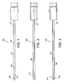
- Figure 1 is a cross-sectional view of a surgical cutting instrument provided with depth markings according to an exemplary embodiment of the present invention.
- Figure 2 is a top view of the surgical cutting instrument of Figure 1 .
- Figure 3 is a side view of the surgical cutting instrument of Figure 2 and illustrating the depth markings.
- the present invention provides a surgical cutting instrument comprising a tubular member provided with a plurality of markings (for example, depth markings) to aid a surgeon in assessing the dimensions (for example, the depth) of the tissue or structure that is cut or shaped.
- markings for example, depth markings
- the tubular member is an outer tubular member of a cutting instrument having a proximal end and a distal end.
- An inner tubular member includes a proximal end portion having cutting means (or cutter), and a distal end portion.
- the inner tubular member is rotatably disposed within the outer tubular member.
- the cutting means or cutter is rotatably disposed within the outer tubular member adjacent to an outer cutting aperture and adjacent the plurality of markings.
- the present invention also provides a method of conducting an arthroscopic surgical procedure using a surgical cutting instrument provided with depth markings.
- the method comprises the steps of: (i) providing a surgical cutting instrument having an outer tubular member with a plurality of markings, for example, depth markings; (ii) positioning the surgical cutting instrument in the proximity of a surgical site undergoing an arthroscopic procedure; and (iii) employing the surgical cutting instrument to conduct the arthroscopic procedure.
- Figures 1-3 illustrate an exemplary embodiment of a surgical cutting instrument 100 of the present invention, which is provided with an outer tubular member having a plurality of markings (for example, depth markings) to aid a surgeon in assessing the dimensions (for example, the shape or depth) of the tissue or structure that is being cut or shaped with the cutting instrument.
- markings for example, depth markings
- surgical cutting instrument 100 comprises an elongate tubular member 50 having a proximal end 52 and a distal end 54.
- An inner tubular member (not shown) includes a proximal end portion having cutting means (not shown), and a distal end portion.
- the inner tubular member may be rotatably disposed within the tubular member 50.
- the cutting means or cutter may be rotatably disposed within the tubular member 50 adjacent to an outer cutting aperture or window 55.
- the cutting aperture 55 may be provided with a first edge and a second edge (for example, a first lateral edge and a second lateral edge) each of the edges being provided with a plurality of cutting teeth having various geometries, for example, a pyramidal configuration.
- the plurality of teeth may be positioned along the lateral cutting edges of the window 55, and they may be configured to allow easy penetration into tissue.
- the cutting edges may be formed by laser cutting technology, for example.
- the teeth of each edge may be symmetrically disposed relative to the tube axis when viewed in a plan view. In another embodiment, the teeth may be asymmetrically disposed.
- the cutting window 55 may be symmetrically or asymmetrically disposed relative to the tube axis when viewed in a plan view.
- the tubular member 50 may be formed from a medically acceptable material such as stainless steel, and may have a cylindrical or ellipsoidal cross-section, among others.
- a plurality of markings 90 are provided at the distal end 54 of the tubular member 50. Markings 90 aid a surgeon in assessing the dimensions (for example, the depth) of the cut or incision performed during arthroscopic surgery with the surgical cutting instrument 100. Markings 90 may be laser sliced or laser cut, for example, or may be formed by other known techniques in the art. As illustrated in Figure 3 , markings 90 may be provided only on one side of the outer surface of the tubular member 50, for example, only on one lateral side or on two lateral sides of the tubular member 50. Markings 90 may comprise, for example, a plurality of parallel lines that are about perpendicular to longitudinal axis 51 ( Figure 1 ) of the tubular member 50. Markings 90 may be provided, however, in other geometries and configurations, and in directions which are not about perpendicular to the longitudinal axis of the cutting instrument, depending on the characteristics of the arthroscopic surgery involved, and as desired.
- An inner tubular member may be disposed coaxially or concentrically within the outer tube 50, so that the cutting means of the inner tubular member is disposed at a distal end of the inner tube.
- the inner and outer tubes may be formed from a medically acceptable material such as stainless steel, and may have a cylindrical or ellipsoidal cross-section, among others.
- the inner member is tubular so that the loose tissue resulting from a cutting, resecting or abrading procedure can be aspirated through the lumen of the inner member.
- the proximal ends of the inner and outer members may include hubs which attach to a handpiece having a motor for rotating the inner member relative to the outer member 50.
- the cutting instrument or shaver 100 with a plurality of markings described above may be part of an arthroscopic shaver employed in various surgical medical procedures such as conventional open surgeries or in other, less invasive, techniques that use cannulas or various port access devices.
- the present invention has applications in surgical procedures where the target tissue is ablated or shaped, and may be employed in cutting various body parts such as the knee, shoulder, hip, ankle, elbow, hand or foot.
- the tubular member 100 of the present invention may be part of an arthroscopic shaver employed in arthroscopic surgery of a knee joint or hip structure.
Landscapes
- Health & Medical Sciences (AREA)
- Surgery (AREA)
- Life Sciences & Earth Sciences (AREA)
- Biomedical Technology (AREA)
- Nuclear Medicine, Radiotherapy & Molecular Imaging (AREA)
- Engineering & Computer Science (AREA)
- Orthopedic Medicine & Surgery (AREA)
- Heart & Thoracic Surgery (AREA)
- Medical Informatics (AREA)
- Molecular Biology (AREA)
- Animal Behavior & Ethology (AREA)
- General Health & Medical Sciences (AREA)
- Public Health (AREA)
- Veterinary Medicine (AREA)
- Surgical Instruments (AREA)
Abstract
A surgical cutting instrument (100) with a tubular member (50) provided with a plurality of markings (90) (for example, depth markings) to aid a surgeon in assessing the dimensions (for example, the depth) of the tissue or structure that is cut or shaped. The tubular member may be an outer tubular member of a cutting instrument having a proximal end and a distal end. An inner tubular member having cutting means may be rotatably disposed within the outer tubular member. The cutting means or cutter may be rotatably disposed within the outer tubular member adjacent to an outer cutting aperture (55) and adjacent the plurality of markings.
Description
- The present invention is directed to surgical cutting instruments having relatively movable inner tubular members.
- Surgical cutting instruments in which an inner member is rotated within an elongate tubular outer member are known in surgical procedures where access to the surgical site is via a narrow portal or passage. Typically, the tubular outer member has a distal end with an opening defining a cutting port or window. The inner member has a distal end with a cutting tip for engaging bodily tissue via the opening. Proximal ends of the inner and outer members commonly include hubs which attach to a handpiece having a motor for rotating the inner member relative to the outer member. The distal end of the inner member can have various configurations dependent upon the surgical procedure to be performed. Often the inner member is tubular so that the loose tissue resulting from a cutting, resecting or abrading procedure can be aspirated through the lumen of the inner member.
- An improved cutting instrument used in performing closed surgery, such as arthroscopic surgery, that can provide information regarding the dimensions of the tissue being cut or shaped during a cutting, resecting or abrading procedure is needed. A method of conducting arthroscopic surgery, wherein the step of cutting (or resecting or abrading) and the step of providing information about the tissue being cut or shaped is performed using the same cutting instrument, is also needed.
- The present invention provides a surgical cutting instrument comprising a tubular member provided with a plurality of markings (for example, depth markings) to aid a surgeon in assessing the dimensions (for example, the depth) of the tissue or structure that is cut or shaped. The tubular member may be part of a surgical arthroscopic cutting instrument. The present invention also provides a method of conducting an arthroscopic surgical procedure wherein the step of cutting, resecting, or abrading, and the step of providing information about the tissue being cut or shaped are performed using the same cutting instrument.
- Other features and advantages of the present invention will become apparent when the following detailed description is read in conjunction with the accompanying drawings, in which:
-
Figure 1 is a cross-sectional view of a surgical cutting instrument provided with depth markings according to an exemplary embodiment of the present invention. -
Figure 2 is a top view of the surgical cutting instrument ofFigure 1 . -
Figure 3 is a side view of the surgical cutting instrument ofFigure 2 and illustrating the depth markings. - The following description is provided to enable any person skilled in the art to make and use the invention and sets forth the best modes contemplated by the inventors of carrying out their invention. Various modifications, however, will remain readily apparent to those skilled in the art.
- The present invention provides a surgical cutting instrument comprising a tubular member provided with a plurality of markings (for example, depth markings) to aid a surgeon in assessing the dimensions (for example, the depth) of the tissue or structure that is cut or shaped.
- According to an exemplary embodiment, the tubular member is an outer tubular member of a cutting instrument having a proximal end and a distal end. An inner tubular member includes a proximal end portion having cutting means (or cutter), and a distal end portion. The inner tubular member is rotatably disposed within the outer tubular member. The cutting means or cutter is rotatably disposed within the outer tubular member adjacent to an outer cutting aperture and adjacent the plurality of markings.
- The present invention also provides a method of conducting an arthroscopic surgical procedure using a surgical cutting instrument provided with depth markings. The method comprises the steps of: (i) providing a surgical cutting instrument having an outer tubular member with a plurality of markings, for example, depth markings; (ii) positioning the surgical cutting instrument in the proximity of a surgical site undergoing an arthroscopic procedure; and (iii) employing the surgical cutting instrument to conduct the arthroscopic procedure.
-
Figures 1-3 illustrate an exemplary embodiment of asurgical cutting instrument 100 of the present invention, which is provided with an outer tubular member having a plurality of markings (for example, depth markings) to aid a surgeon in assessing the dimensions (for example, the shape or depth) of the tissue or structure that is being cut or shaped with the cutting instrument. - As shown in the drawings,
surgical cutting instrument 100 comprises an elongatetubular member 50 having aproximal end 52 and adistal end 54. An inner tubular member (not shown) includes a proximal end portion having cutting means (not shown), and a distal end portion. The inner tubular member may be rotatably disposed within thetubular member 50. The cutting means or cutter may be rotatably disposed within thetubular member 50 adjacent to an outer cutting aperture orwindow 55. - In exemplary embodiments, the
cutting aperture 55 may be provided with a first edge and a second edge (for example, a first lateral edge and a second lateral edge) each of the edges being provided with a plurality of cutting teeth having various geometries, for example, a pyramidal configuration. The plurality of teeth may be positioned along the lateral cutting edges of thewindow 55, and they may be configured to allow easy penetration into tissue. The cutting edges may be formed by laser cutting technology, for example. The teeth of each edge may be symmetrically disposed relative to the tube axis when viewed in a plan view. In another embodiment, the teeth may be asymmetrically disposed. In other embodiments, thecutting window 55 may be symmetrically or asymmetrically disposed relative to the tube axis when viewed in a plan view. Thetubular member 50 may be formed from a medically acceptable material such as stainless steel, and may have a cylindrical or ellipsoidal cross-section, among others. - As shown in
Figure 3 , a plurality ofmarkings 90 are provided at thedistal end 54 of thetubular member 50.Markings 90 aid a surgeon in assessing the dimensions (for example, the depth) of the cut or incision performed during arthroscopic surgery with thesurgical cutting instrument 100.Markings 90 may be laser sliced or laser cut, for example, or may be formed by other known techniques in the art. As illustrated inFigure 3 ,markings 90 may be provided only on one side of the outer surface of thetubular member 50, for example, only on one lateral side or on two lateral sides of thetubular member 50.Markings 90 may comprise, for example, a plurality of parallel lines that are about perpendicular to longitudinal axis 51 (Figure 1 ) of thetubular member 50.Markings 90 may be provided, however, in other geometries and configurations, and in directions which are not about perpendicular to the longitudinal axis of the cutting instrument, depending on the characteristics of the arthroscopic surgery involved, and as desired. - An inner tubular member may be disposed coaxially or concentrically within the
outer tube 50, so that the cutting means of the inner tubular member is disposed at a distal end of the inner tube. The inner and outer tubes may be formed from a medically acceptable material such as stainless steel, and may have a cylindrical or ellipsoidal cross-section, among others. Preferably, the inner member is tubular so that the loose tissue resulting from a cutting, resecting or abrading procedure can be aspirated through the lumen of the inner member. The proximal ends of the inner and outer members may include hubs which attach to a handpiece having a motor for rotating the inner member relative to theouter member 50. - The cutting instrument or
shaver 100 with a plurality of markings described above may be part of an arthroscopic shaver employed in various surgical medical procedures such as conventional open surgeries or in other, less invasive, techniques that use cannulas or various port access devices. The present invention has applications in surgical procedures where the target tissue is ablated or shaped, and may be employed in cutting various body parts such as the knee, shoulder, hip, ankle, elbow, hand or foot. For example, thetubular member 100 of the present invention may be part of an arthroscopic shaver employed in arthroscopic surgery of a knee joint or hip structure. - Although the present invention has been described in connection with preferred embodiments, many modifications and variations will become apparent to those skilled in the art. While preferred embodiments of the invention have been described and illustrated above, it should be understood that these are exemplary of the invention and are not to be considered as limiting. Accordingly, it is not intended that the present invention be limited to the illustrated embodiments, but only by the appended claims.
Claims (10)
- An arthroscopic cutting instrument, comprising:an outer tubular member comprising a distal end, a proximal end, an inner cylindrical surface, an outer cylindrical surface, a cutting window located at the distal end for receiving anatomical tissue therethrough, and a plurality of markings provided on the outer cylindrical surface and adjacent the distal opening; andan inner tubular member rotatably disposed within the outer tubular member, the inner tubular member comprising cutting means disposed at a most distal end of the inner tubular member.
- The arthroscopic cutting instrument of claim 1, wherein the cutting means is a shaver blade or an abrader.
- The arthroscopic cutting instrument of claim 1, wherein at least one of the plurality of markings is formed by laser slicing or laser cutting.
- The arthroscopic cutting instrument of claim 1, wherein the plurality of markings extend in a direction about perpendicular to the longitudinal axis of the outer tubular member.
- The arthroscopic cutting instrument of claim 1, wherein the cutting window is in communication with the cutting means of the inner tubular member.
- The arthroscopic cutting instrument of claim 1, wherein the cutting window is provided with a first lateral cutting edge and a second lateral cutting edge.
- The arthroscopic cutting instrument of claim 6, wherein the cutting window is provided with a first plurality of teeth located on the first lateral cutting edge, and a second plurality of teeth located on the second lateral cutting edge.
- The arthroscopic cutting instrument of claim 7, wherein the first and second plurality of teeth are asymmetrically located relative to the longitudinal axis of the outer tubular member.
- The arthroscopic cutting instrument of claim 7, wherein the first and second plurality of teeth are symmetrically located relative to the longitudinal axis of the outer tubular member.
- The arthroscopic cutting instrument of claim 7, wherein the first and second plurality of teeth have a pyramidal geometry.
Applications Claiming Priority (1)
| Application Number | Priority Date | Filing Date | Title |
|---|---|---|---|
| US89549607P | 2007-03-19 | 2007-03-19 |
Publications (1)
| Publication Number | Publication Date |
|---|---|
| EP1972288A1 true EP1972288A1 (en) | 2008-09-24 |
Family
ID=39474012
Family Applications (1)
| Application Number | Title | Priority Date | Filing Date |
|---|---|---|---|
| EP08102715A Withdrawn EP1972288A1 (en) | 2007-03-19 | 2008-03-18 | Shaver blade with depth markings |
Country Status (2)
| Country | Link |
|---|---|
| US (1) | US20080234713A1 (en) |
| EP (1) | EP1972288A1 (en) |
Cited By (1)
| Publication number | Priority date | Publication date | Assignee | Title |
|---|---|---|---|---|
| GB2465631A (en) * | 2008-11-28 | 2010-06-02 | Orthomimetics Ltd | Arthroscope with depth gauge |
Families Citing this family (17)
| Publication number | Priority date | Publication date | Assignee | Title |
|---|---|---|---|---|
| USD597204S1 (en) * | 2007-05-09 | 2009-07-28 | Karl Storz Gmbh & Co. Kg | Medical instrument |
| USD624653S1 (en) * | 2008-03-20 | 2010-09-28 | Bien-Air Holding Sa | Chirurgical lame shaver |
| USD622846S1 (en) * | 2008-09-03 | 2010-08-31 | Karl Storz Gmbh & Co. Kg | Shaft for medical instrument |
| USD728098S1 (en) * | 2013-04-15 | 2015-04-28 | Karl Storz Gmbh & Co. Kg | Trocar |
| USD727499S1 (en) * | 2013-04-15 | 2015-04-21 | Karl Storz Gmbh & Co. Kg | Trocar |
| USD728099S1 (en) * | 2013-04-15 | 2015-04-28 | Karl Storz Gmbh & Co. Kg | Trocar |
| US10149957B2 (en) | 2013-10-03 | 2018-12-11 | University Of Utah Research Foundation | Tracheal intubation system including a laryngoscope |
| EP3193748B1 (en) | 2014-09-18 | 2020-07-01 | Mayo Foundation for Medical Education and Research | Soft tissue cutting device |
| US10864055B2 (en) | 2017-10-13 | 2020-12-15 | Sonex Health, Inc. | Tray for a soft tissue cutting device and methods of use |
| USD925738S1 (en) * | 2018-07-25 | 2021-07-20 | Progressive Medical, Inc. | Surgical blade |
| EP3908215B1 (en) | 2019-01-11 | 2023-08-02 | Mayo Foundation for Medical Education and Research | Micro-invasive surgical device |
| EP3975889B1 (en) | 2019-05-29 | 2024-10-16 | Mayo Foundation for Medical Education and Research | Micro-invasive surgical device and methods of use |
| US12004767B2 (en) | 2021-01-08 | 2024-06-11 | Sonex Health, Inc. | Surgical cutting device for ultrasonic guided soft tissue surgery |
| US12251122B2 (en) | 2021-04-30 | 2025-03-18 | Sonex Health, Inc. | Cutting device for trigger finger and other soft tissues |
| USD989961S1 (en) | 2021-04-30 | 2023-06-20 | Sonex Health, Inc. | Soft tissue cutting device |
| US12605181B2 (en) | 2022-01-31 | 2026-04-21 | Sonex Health, Inc. | Trigger thumb treatment devices and methods |
| WO2024044237A1 (en) | 2022-08-25 | 2024-02-29 | Sonex Health, Inc. | De quervain's treatment device |
Citations (3)
| Publication number | Priority date | Publication date | Assignee | Title |
|---|---|---|---|---|
| US5643303A (en) * | 1993-01-26 | 1997-07-01 | Donahue; John R. | Flexible surgical instrument |
| US20020031745A1 (en) * | 2000-08-02 | 2002-03-14 | Ajay Kumar | Endosseous implant drill |
| US20060196038A1 (en) * | 2005-03-02 | 2006-09-07 | Van Wyk Robert A | Arthroscopic shaver with two pass inner blade and method of manufacturing same |
-
2008
- 2008-03-17 US US12/049,986 patent/US20080234713A1/en not_active Abandoned
- 2008-03-18 EP EP08102715A patent/EP1972288A1/en not_active Withdrawn
Patent Citations (3)
| Publication number | Priority date | Publication date | Assignee | Title |
|---|---|---|---|---|
| US5643303A (en) * | 1993-01-26 | 1997-07-01 | Donahue; John R. | Flexible surgical instrument |
| US20020031745A1 (en) * | 2000-08-02 | 2002-03-14 | Ajay Kumar | Endosseous implant drill |
| US20060196038A1 (en) * | 2005-03-02 | 2006-09-07 | Van Wyk Robert A | Arthroscopic shaver with two pass inner blade and method of manufacturing same |
Cited By (1)
| Publication number | Priority date | Publication date | Assignee | Title |
|---|---|---|---|---|
| GB2465631A (en) * | 2008-11-28 | 2010-06-02 | Orthomimetics Ltd | Arthroscope with depth gauge |
Also Published As
| Publication number | Publication date |
|---|---|
| US20080234713A1 (en) | 2008-09-25 |
Similar Documents
| Publication | Publication Date | Title |
|---|---|---|
| US20080234713A1 (en) | Shaver blade with depth markings | |
| EP1958576A2 (en) | Double cut shaver | |
| US11903607B2 (en) | Flexible surgical device for tissue removal | |
| EP2667794B1 (en) | Surgical cutting instrument with distal suction capabiilty | |
| EP2667803B1 (en) | Surgical cutting instrument with distal suction capability | |
| KR101495551B1 (en) | Anti-coring device for a surgical morcellator | |
| EP2311394B1 (en) | Cannulated arthroscopic knife | |
| EP2412320B1 (en) | Labrum retracting burr | |
| US6419684B1 (en) | End-cutting shaver blade for axial resection | |
| US8419653B2 (en) | Spinal access and neural localization | |
| US5429117A (en) | Method and system for performing endoscopic surgery at locations where tissue inserts into bone | |
| US8657840B2 (en) | Surgical instrument with distal suction capability | |
| US10722260B1 (en) | Modified surgical scalpel with polyurethane mated sheath: for ultrasound assisted carpal tunnel surgeries | |
| US8216185B2 (en) | Cannulated apertured grooved director | |
| US20080243163A1 (en) | Perforating Trocar | |
| JP2016501642A (en) | Discectomy device and method | |
| KR20160058951A (en) | Tissue incision device | |
| US20130066149A1 (en) | Endoscopic hook blade and use thereof | |
| EP4740873A2 (en) | Cutting device for trigger finger and other soft tissues | |
| US20120123460A1 (en) | Trocar | |
| US20090182367A1 (en) | Adjustable Width Trocar | |
| US20250000543A1 (en) | Surgical blade for performing cutting and suction | |
| HK40045151A (en) | Medical instrument for percutaneous release procedures |
Legal Events
| Date | Code | Title | Description |
|---|---|---|---|
| PUAI | Public reference made under article 153(3) epc to a published international application that has entered the european phase |
Free format text: ORIGINAL CODE: 0009012 |
|
| AK | Designated contracting states |
Kind code of ref document: A1 Designated state(s): AT BE BG CH CY CZ DE DK EE ES FI FR GB GR HR HU IE IS IT LI LT LU LV MC MT NL NO PL PT RO SE SI SK TR |
|
| AX | Request for extension of the european patent |
Extension state: AL BA MK RS |
|
| AKX | Designation fees paid | ||
| REG | Reference to a national code |
Ref country code: DE Ref legal event code: 8566 |
|
| STAA | Information on the status of an ep patent application or granted ep patent |
Free format text: STATUS: THE APPLICATION IS DEEMED TO BE WITHDRAWN |
|
| 18D | Application deemed to be withdrawn |
Effective date: 20090325 |