EP1971521B1 - Stiff-in-plane gimbaled tiltrotor hub - Google Patents
Stiff-in-plane gimbaled tiltrotor hub Download PDFInfo
- Publication number
- EP1971521B1 EP1971521B1 EP06849210A EP06849210A EP1971521B1 EP 1971521 B1 EP1971521 B1 EP 1971521B1 EP 06849210 A EP06849210 A EP 06849210A EP 06849210 A EP06849210 A EP 06849210A EP 1971521 B1 EP1971521 B1 EP 1971521B1
- Authority
- EP
- European Patent Office
- Prior art keywords
- yoke
- rotor
- hub
- rotor hub
- rotary wing
- Prior art date
- Legal status (The legal status is an assumption and is not a legal conclusion. Google has not performed a legal analysis and makes no representation as to the accuracy of the status listed.)
- Expired - Lifetime
Links
Images



Classifications
-
- B—PERFORMING OPERATIONS; TRANSPORTING
- B64—AIRCRAFT; AVIATION; COSMONAUTICS
- B64C—AEROPLANES; HELICOPTERS
- B64C29/00—Aircraft capable of landing or taking-off vertically, e.g. vertical take-off and landing [VTOL] aircraft
- B64C29/0008—Aircraft capable of landing or taking-off vertically, e.g. vertical take-off and landing [VTOL] aircraft having its flight directional axis horizontal when grounded
- B64C29/0016—Aircraft capable of landing or taking-off vertically, e.g. vertical take-off and landing [VTOL] aircraft having its flight directional axis horizontal when grounded the lift during taking-off being created by free or ducted propellers or by blowers
- B64C29/0033—Aircraft capable of landing or taking-off vertically, e.g. vertical take-off and landing [VTOL] aircraft having its flight directional axis horizontal when grounded the lift during taking-off being created by free or ducted propellers or by blowers the propellers being tiltable relative to the fuselage
-
- B—PERFORMING OPERATIONS; TRANSPORTING
- B64—AIRCRAFT; AVIATION; COSMONAUTICS
- B64C—AEROPLANES; HELICOPTERS
- B64C27/00—Rotorcraft; Rotors peculiar thereto
- B64C27/32—Rotors
-
- B—PERFORMING OPERATIONS; TRANSPORTING
- B64—AIRCRAFT; AVIATION; COSMONAUTICS
- B64C—AEROPLANES; HELICOPTERS
- B64C27/00—Rotorcraft; Rotors peculiar thereto
- B64C27/82—Rotorcraft; Rotors peculiar thereto characterised by the provision of an auxiliary rotor or fluid-jet device for counter-balancing lifting rotor torque or changing direction of rotorcraft
Definitions
- the present invention relates to the field of rotary-wing aircraft rotor-hubs.
- the present invention relates to a stiff-in-plane, gimbaled tiltrotor hub.
- Rotor-hubs have been in use for many years. There are numerous successful designs of rotor-hubs for various types of rotary-wing aircraft. Rotor-hubs are typically designed for, and therefore particularly well suited as, a means of connecting rotor-blades to a rotating shaft or mast.
- a stiff-in-plane rotor-hub is used in rotary-wing aircraft wherein the natural frequency of in-plane/lead-lag vibration of the rotor-blades is higher than both the rotor rotational frequency and the natural frequency of out-of-plane/flapping vibration of the rotor-blades.
- a soft-in-plane rotor-hub is used where the natural frequency of in-plane/lead-lag vibration of the rotor-blades is lower than both the rotor rotational frequency and the natural frequency of out-of-plane/flapping vibration of the rotor blades. It is well known that the rotor-blades and associated rotor-hub of a rotary-wing aircraft become more dynamically unstable as the natural frequencies of out-of-plane/flapping vibration of the rotor-blades and in-plane/lead-lag vibration of the rotor-blades converge toward equal values.
- a rotary-wing aircraft it is not uncommon for a rotary-wing aircraft to be designed such that the natural frequencies of out-of-plane/flapping vibration of the rotor-blades and in-plane/lead-lag vibration of the rotor-blades maintain a minimum separation of about 25% of the rotor rotational frequency.
- stiff-in-plane and soft-in-plane systems In choosing between stiff-in-plane and soft-in-plane systems, several high level generalizations are often considered while designing a rotary-wing aircraft.
- the combined weight of the rotor-hub and rotor-blades of a stiff-in-plane, rotary-wing aircraft are typically heavier than the combined weight of the rotor-hub and rotor-blades of a soft-in-plane, rotary-wing aircraft.
- stiff-in-plane componentry is currently thought to be a better solution for traveling at higher speeds and/or producing greater thrust, while more readily maintaining dynamic vibratory stability.
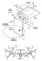
- Prior Art Figure 1 shows a schematic of a rotor-hub which illustrates the ⁇ 3 angle in relation to a rotor system. Because one end of the pitch horn is restrained by the pitch link and the other end of the pitch horn is attached to the blade, a pitch change will occur as the blade flaps. Hence, the ⁇ 3 angle represents a correlation between the rotor flapping and rotor-blade pitch.
- a rotor system with a positive ⁇ 3 angle will experience a nose-down pitch, while a rotor system with a negative ⁇ 3 angle will experience a nose-up pitch.
- the ⁇ 3 angle is manipulated to provide dynamic stability as well as to reduce rotor flapping amplitudes during gust disturbances and/or pilot maneuvers.
- the ⁇ 3 angle on a three-bladed, tilt-rotor aircraft is typically set to values near -15 degrees, which provides an adequate level of stability and flapping attenuation.
- the present invention provides significant advantages, including: (1) allowing the use of more than three blades in a rotor system of a tilt-rotor aircraft; (2) reducing opportunity for pitch horn damage due to debris or ballistic attack; (3) reducing opportunity for drive link damage due to debris or ballistic attack; (4) offering hub-spring redundancy; and (5) improving force transfer between hub-springs and the yoke.
- the present invention is an improved rotor-hub which allows connection to four or more rotor-blades while maintaining optimal ⁇ 3 angles.
- the rotor-hub of the present invention allows for the incorporation of four-bladed rotor systems on tilt-rotor rotary-wing aircraft.
- the present invention may alternatively be used with any other rotary-wing vehicle/craft.
- the rotor-hub of the present invention may alternatively be used with rotary system having more or fewer than four rotor-blades.
- FIG. 2 depicts a tilt-rotor, rotary-wing aircraft incorporating a rotor-hub of the present invention.
- Figure 2 illustrates a tilt-rotor aircraft 11 in an airplane mode of flight operation. Wings 15, 17 are utilized to lift craft body 13 in response to the action of rotor systems 19, 21.
- Each rotor system 19, 21 is illustrated as having four rotor-blades 23. Nacelles 25, 27 substantially enclose rotor-hubs 29, obscuring rotor-hubs 29 from view in Figure 2 .
- each rotor system 19, 21 is driven by an engine (not shown) substantially housed within each nacelle 25, 27, respectively.
- FIG 3A illustrates a perspective view of the preferred embodiment of the rotor-hub 29 of the present invention.
- Rotor-hub 29 is illustrated as comprising a yoke 31 having yoke arms 33 and yoke straps 35.
- Yoke arms 33 are integrally connected to yoke straps 35.
- yoke 31 is constructed of composite materials. More specifically, yoke 31 is constructed of a multiplicity of discrete bonded layers of directional fiber material. However, yoke 31 may alternatively be constructed of any other suitable material in any other suitable fashion.
- yoke 31 is illustrated as having four yoke arms 33, other rotor-hub configurations according to the present invention may comprise more or fewer than four yoke arms 33 for connection with more or fewer than four rotor-blades 23, respectively.
- Rotor-hub 29 is further illustrated with representative pitch change axes 37A, 37B, about which the pitch of rotor-blades 23 (see Figure 2 ) is altered. Additionally, rotor-hub 29 is illustrated with a representative mast rotation axis 39, about which a mast (not shown) is rotated when driven by an operably associated transmission (not shown).
- Outboard feathering bearings 41 are attached to the outermost portions of yoke arms 33. Outboard feathering bearings 41 allow at least some degree of rotation of rotor-blades 23 about pitch change axes 37A, 37B. Centrifugal force (CF) bearings 43 are attached to outboard feathering bearings 41. CF bearings 43 are the primary intermediary connective devices between rotor-blades 23 and rotor-hub 29. CF bearings 43 withstand the often enormous centrifugal force generated by rotating rotor-blades 23 about mast rotation axis 39.
- Figure 3B illustrates a simplified view of yoke 31 of rotor-hub 29.
- a central void space 30 is defined by inner walls 32 of yoke 31.
- hub-spring 45 includes an inner-core 47 comprising a first series of various alternatingly stacked rubber elements and metal shim elements (neither shown in detail) sandwiched between an upper, outer connecting shell 49 and an inner shell 51 and a second series of various alternatingly stacked rubber elements and metal shim elements sandwiched between a lower, outer shell 50 and another inner shell 51.
- Shells 49-51 are illustrated as being constructed of metal.
- Hub-spring 45 allows gimbaling of yoke 31 with respect to the mast and mast rotation axis 39. Hub-spring 45 also accommodates flapping of rotor-blades 23 and transfers thrust.
- rotor-hub 29 further comprises four pitch horns 53.
- Pitch horns 53 comprise pitch horn arms 55 and pitch horn inboard beams 57.
- Pitch horns 53 are rotatably connected to crotches 59 through inboard feathering bearings 61.
- Inboard feathering bearings 61 are substantially centered along corresponding pitch change axes 37A, 37B.
- Inboard feathering bearings 61 are operably associated with like-sized apertures in pitch horns 53 located substantially at the intersection of pitch horn arms 55 and pitch horn inboard beams 57.
- Grips are connected to pitch horn inboard beams 57 such that, when pitch horns 53 are rotated about their corresponding pitch change axes 37A, 37B, grips cause rotor-blades 23 (shown in Figure 2 ), which are attached to grips, to correspondingly rotate about the pitch change axes 37A, 37B.
- Ends 63 of pitch horns 53 are illustrated as being located in a neutral/nominal position when ends 63 are substantially centered about the plane created by pitch change axes 37A, 37B.
- Ends 63 of pitch horns 53 are connected to upper ends of pitch links 65.
- Pitch links 65 are rod-like elements oriented substantially parallel to mast rotation axis 39.
- Pitch horns 53 are located substantially within central void space 30.
- a central void column is defined by extending the vertical boundaries of central void space 30 both upward and downward and represents the vertical footprint of central void space 30.
- the central void column occupies at least the space between upper footprint 34A and lower footprint 34B as illustrated in Figure 3B .
- arms 55 extend outside of the central void column.
- arms 55 may alternatively remain within the central void column.
- rotor-hub 29 further comprises a constant velocity/homokinetic joint (not fully shown) which comprises drive links 67.
- Drive links 67 are oriented substantially parallel to the plane created by pitch change axes 37A, 37B.
- One end of each drive link 67 is adapted for connection to a trunnion (not shown) splined to the mast/drive shaft (not shown). The trunnion transfers rotational force from the mast to drive links 67.
- each drive link 67 is adapted for attachment to drive legs 68 of connecting shell 49 (see Figures 10 and 11 ) which transfers the rotational force from drive links 67 to connecting shell 49.
- Connecting shell 49 is connected to yoke 31 along yoke straps 35 such that rotational force is transferred from connecting shell 49 to yoke 31.
- Figure 6 illustrates a top view of rotor-hub 29, while Figure 7 illustrates a cross-sectional view of rotor-hub 29 taken along a line 7-7 of Figure 3A corresponding to the pitch change axis 37A, 37B.
- a rotor-hub not in accordance with the present invention also incorporates a hub-spring 71 similar to hub-spring 45. However, connecting shell 72 of hub-spring 45 is located below a yoke 73.
- rotor-hub 69 is substantially similar to rotor-hub 29 and comprises substantially similar components with three main differences: (1) connecting shell 72 is located on the underside of yoke 73 rather than on the upper side of yoke 73; (2) pitch horns 75 are curved, rod-like structures, portions of which are located slightly above the plane created by pitch change axes 77A, 77B but still within a central void space defined by the inner walls 32 of yoke 73; and (3) drive links 81 are illustrated as being located slightly below the plane created by pitch change axes 77A, 77B but still substantially within central void column.
- rotor-hub 69 may alternatively comprise pitch horns 53 which would lie substantially within the plane created by pitch change axes 77A, 77B.
- hub-spring 71 allows gimbaling of yoke 73 with respect to the mast and mast rotation axis 39 (shown in Figure 3A ). Hub-spring 71 also accommodates flapping of rotor-blades 23 (shown in Figure 2 ) and transfers thrust.
- rotor-hub 83 is substantially similar to rotor-hub 29 and comprises substantially similar components except that two connecting shells 86 are present within rotor-hub 83.
- One connecting shell 86 is mounted on the underside of yoke 87 while another connecting shell 86 is mounted on the upper side of yoke 87.
- One important advantage of rotor-hub 83 is connecting shell 86 redundancy. For example, if one of connecting shells 86 is damaged by a ballistic round or fail for any other reason, the remaining connecting shell 86 can continue to function normally.
- hub-springs 85 allows gimbaling of yoke 87 with respect to the mast and mast rotation axis 39 (shown in Figure 3A ). Hub-springs 85 also accommodate flapping of rotor-blades 23 (shown in Figure 2 ) and transfers thrust.
- An important advantage of the present invention is that, while providing for use of four or more rotor-blades per rotor-hub, the majority of components are compactly packaged substantially within an interior void space between the yoke straps.
- This arrangement makes the rotor-hubs of the present invention a tougher target for enemy combatants and a less likely target for unintentional debris.
- the present invention allows for several variations in pitch horn travel. For example, where a connecting shell is only located on the top of a yoke, more space is available for downward pitch horn travel. Similarly, where a connecting shell is only located on the underside of a yoke more space is available for upward pitch horn travel.
- pitch horn travel may be more evenly divided between upward travel and downward travel.
Landscapes
- Engineering & Computer Science (AREA)
- Aviation & Aerospace Engineering (AREA)
- Mechanical Engineering (AREA)
- Wind Motors (AREA)
- Turbine Rotor Nozzle Sealing (AREA)
- Tires In General (AREA)
- Valve-Gear Or Valve Arrangements (AREA)
- Toys (AREA)
- Transmission Devices (AREA)
- Apparatuses For Generation Of Mechanical Vibrations (AREA)
Description
- The present invention relates to the field of rotary-wing aircraft rotor-hubs. In particular, the present invention relates to a stiff-in-plane, gimbaled tiltrotor hub.
- Rotor-hubs have been in use for many years. There are numerous successful designs of rotor-hubs for various types of rotary-wing aircraft. Rotor-hubs are typically designed for, and therefore particularly well suited as, a means of connecting rotor-blades to a rotating shaft or mast.
- It is common for those of ordinary skill in the art of rotary-wing aircraft design to classify rotor-hubs into two major categories, "stiff-in-plane" and "soft-in-plane." A stiff-in-plane rotor-hub is used in rotary-wing aircraft wherein the natural frequency of in-plane/lead-lag vibration of the rotor-blades is higher than both the rotor rotational frequency and the natural frequency of out-of-plane/flapping vibration of the rotor-blades. A soft-in-plane rotor-hub is used where the natural frequency of in-plane/lead-lag vibration of the rotor-blades is lower than both the rotor rotational frequency and the natural frequency of out-of-plane/flapping vibration of the rotor blades. It is well known that the rotor-blades and associated rotor-hub of a rotary-wing aircraft become more dynamically unstable as the natural frequencies of out-of-plane/flapping vibration of the rotor-blades and in-plane/lead-lag vibration of the rotor-blades converge toward equal values. Accordingly, it is not uncommon for a rotary-wing aircraft to be designed such that the natural frequencies of out-of-plane/flapping vibration of the rotor-blades and in-plane/lead-lag vibration of the rotor-blades maintain a minimum separation of about 25% of the rotor rotational frequency.
- In choosing between stiff-in-plane and soft-in-plane systems, several high level generalizations are often considered while designing a rotary-wing aircraft. The combined weight of the rotor-hub and rotor-blades of a stiff-in-plane, rotary-wing aircraft are typically heavier than the combined weight of the rotor-hub and rotor-blades of a soft-in-plane, rotary-wing aircraft. However, stiff-in-plane componentry is currently thought to be a better solution for traveling at higher speeds and/or producing greater thrust, while more readily maintaining dynamic vibratory stability.
- One of the numerous variables in achieving desired dynamic vibratory stability of the rotor-hub and rotor-blades of a stiff-in-plane rotary-wing craft is the δ3 angle. Prior Art
Figure 1 shows a schematic of a rotor-hub which illustrates the δ3 angle in relation to a rotor system. Because one end of the pitch horn is restrained by the pitch link and the other end of the pitch horn is attached to the blade, a pitch change will occur as the blade flaps. Hence, the δ3 angle represents a correlation between the rotor flapping and rotor-blade pitch. As the rotor-blade flaps upward, a rotor system with a positive δ3 angle will experience a nose-down pitch, while a rotor system with a negative δ3 angle will experience a nose-up pitch. The δ3 angle is manipulated to provide dynamic stability as well as to reduce rotor flapping amplitudes during gust disturbances and/or pilot maneuvers. As an example, the δ3 angle on a three-bladed, tilt-rotor aircraft is typically set to values near -15 degrees, which provides an adequate level of stability and flapping attenuation. - Demand is increasing for rotary-wing aircraft to achieve more thrust, higher speeds, and carry heavier loads. For example, there is a demand for more powerful tilt-rotor aircraft. One way of producing more thrust is to increase the number of rotor-blades. Current tilt-rotor aircraft typically utilize three-bladed rotor systems. In three-bladed rotor systems, the pitch horn and pitch link (see Prior Art
Figure 1 ) are usually located generally in-plane with the rotor-hub and outside of the rotor-hub. However, achieving small δ3 angles (e.g., δ3 angles near -15 degrees) for a multi-bladed rotor having four or more blades, while locating the pitch horn and pitch link generally in-plane with the hub and outside of the hub, presents a serious design challenge. The rotor-hub configuration, as described above for multi-bladed rotor systems, does not allow the pitch horns to be located at the proper positions due to structural interferences. Further, it is widely accepted as desirable by those of ordinary skill in the art of rotary-wing aircraft design to configure rotating componentry of rotor systems to remain as close to the axis of rotation as possible to minimize undesirable resultant forces that lead to early component failure. - Document
US 5,620,305 discloses a rotor hub for a rotary wing aircraft according to the preamble ofclaim 1. - Document
US 6,296,444 B1 discloses a rotor hub including a constant velocity joint comprising drive links connected to pillow blocks connecting the drive links to upper and lower hub plates. - While the above described rotor-hub advancements represent significant developments in rotor-hub design, considerable shortcomings remain.
- The present invention is defined by appended
claim 1. - The present invention provides significant advantages, including: (1) allowing the use of more than three blades in a rotor system of a tilt-rotor aircraft; (2) reducing opportunity for pitch horn damage due to debris or ballistic attack; (3) reducing opportunity for drive link damage due to debris or ballistic attack; (4) offering hub-spring redundancy; and (5) improving force transfer between hub-springs and the yoke.
- Additional objectives, features, and advantages will be apparent in the written description that follows.
- The novel features believed characteristic of the invention are set forth in the appended claims. However, the invention itself, as well as, a preferred mode of use, and further objectives and advantages thereof, will best be understood by reference to the following detailed description when read in conjunction with the accompanying drawings, wherein:
- Prior Art
Figure 1 is a simplified schematic representation of the effect of δ3 angle in a rotor system; -
Figure 2 is an elevational view of a tilt-rotor aircraft having a rotor-hub according to the preferred embodiment of the present invention; -
Figure 3A is a perspective view of the rotor-hub used in the tilt-rotor aircraft ofFigure 2 ; -
Figure 3B is a perspective view of the yoke of the rotor-hub ofFigure 3A ; -
Figure 4 is a perspective view of the rotor-hub ofFigure 3A with the connecting shell removed; -
Figure 5 is a top view of the rotor-hub ofFigure 3A with the connecting shell removed; -
Figure 6 is a top view of the rotor-hub ofFigure 3A ; -
Figure 7 is cross-sectional view of the rotor-hub ofFigure 3A taken along the line 7-7 inFigure 3A ; -
Figure 8 is a partial perspective view of a rotor-hub having a connecting shell located below the yoke not in accordance with the present invention; -
Figure 9 is a cross-sectional view of the rotor-hub ofFigure 8 taken along the line 9-9 inFigure 8 ; -
Figure 10 is a perspective view of a rotor-hub having two connecting shells not in accordance with the present invention; and -
Figure 11 is a cross-sectional view of the rotor-hub ofFigure 10 taken along the line 11-11 inFigure 10 . - The present invention is an improved rotor-hub which allows connection to four or more rotor-blades while maintaining optimal δ3 angles. The rotor-hub of the present invention allows for the incorporation of four-bladed rotor systems on tilt-rotor rotary-wing aircraft. However, while specific reference is made to using the present invention with tilt-rotor rotary-wing aircraft, the present invention may alternatively be used with any other rotary-wing vehicle/craft. Further, the rotor-hub of the present invention may alternatively be used with rotary system having more or fewer than four rotor-blades.
-
Figure 2 depicts a tilt-rotor, rotary-wing aircraft incorporating a rotor-hub of the present invention.Figure 2 illustrates a tilt-rotor aircraft 11 in an airplane mode of flight operation.Wings craft body 13 in response to the action ofrotor systems rotor system blades 23. Nacelles 25, 27 substantially enclose rotor-hubs 29, obscuring rotor-hubs 29 from view inFigure 2 . Of course, eachrotor system nacelle -
Figure 3A illustrates a perspective view of the preferred embodiment of the rotor-hub 29 of the present invention. Rotor-hub 29 is illustrated as comprising ayoke 31 havingyoke arms 33 andyoke straps 35.Yoke arms 33 are integrally connected to yoke straps 35. In one embodiment,yoke 31 is constructed of composite materials. More specifically,yoke 31 is constructed of a multiplicity of discrete bonded layers of directional fiber material. However,yoke 31 may alternatively be constructed of any other suitable material in any other suitable fashion. Further, whileyoke 31 is illustrated as having fouryoke arms 33, other rotor-hub configurations according to the present invention may comprise more or fewer than fouryoke arms 33 for connection with more or fewer than four rotor-blades 23, respectively. - Rotor-
hub 29 is further illustrated with representative pitch change axes 37A, 37B, about which the pitch of rotor-blades 23 (seeFigure 2 ) is altered. Additionally, rotor-hub 29 is illustrated with a representativemast rotation axis 39, about which a mast (not shown) is rotated when driven by an operably associated transmission (not shown). - Outboard feathering
bearings 41 are attached to the outermost portions ofyoke arms 33. Outboard featheringbearings 41 allow at least some degree of rotation of rotor-blades 23 about pitch change axes 37A, 37B. Centrifugal force (CF)bearings 43 are attached tooutboard feathering bearings 41.CF bearings 43 are the primary intermediary connective devices between rotor-blades 23 and rotor-hub 29.CF bearings 43 withstand the often enormous centrifugal force generated by rotating rotor-blades 23 aboutmast rotation axis 39. -
Figure 3B illustrates a simplified view ofyoke 31 of rotor-hub 29. Acentral void space 30 is defined byinner walls 32 ofyoke 31. - As illustrated in
Figure 7 , hub-spring 45 includes an inner-core 47 comprising a first series of various alternatingly stacked rubber elements and metal shim elements (neither shown in detail) sandwiched between an upper, outer connectingshell 49 and aninner shell 51 and a second series of various alternatingly stacked rubber elements and metal shim elements sandwiched between a lower,outer shell 50 and anotherinner shell 51. Shells 49-51 are illustrated as being constructed of metal. Hub-spring 45 allows gimbaling ofyoke 31 with respect to the mast andmast rotation axis 39. Hub-spring 45 also accommodates flapping of rotor-blades 23 and transfers thrust. - As can more clearly be seen in
Figure 4 , wherein rotor-hub 29 is illustrated without connectingshell 49, rotor-hub 29 further comprises fourpitch horns 53.Pitch horns 53 comprisepitch horn arms 55 and pitch horn inboard beams 57.Pitch horns 53 are rotatably connected to crotches 59 throughinboard feathering bearings 61.Inboard feathering bearings 61 are substantially centered along corresponding pitch change axes 37A, 37B.Inboard feathering bearings 61 are operably associated with like-sized apertures inpitch horns 53 located substantially at the intersection ofpitch horn arms 55 and pitch horn inboard beams 57. Grips (not shown) are connected to pitch horn inboard beams 57 such that, whenpitch horns 53 are rotated about their corresponding pitch change axes 37A, 37B, grips cause rotor-blades 23 (shown inFigure 2 ), which are attached to grips, to correspondingly rotate about the pitch change axes 37A, 37B. Ends 63 ofpitch horns 53 are illustrated as being located in a neutral/nominal position when ends 63 are substantially centered about the plane created by pitch change axes 37A, 37B. Ends 63 ofpitch horns 53 are connected to upper ends of pitch links 65. Pitch links 65 are rod-like elements oriented substantially parallel tomast rotation axis 39. Movement ofpitch links 65 in either direction along a path parallel tomast rotation axis 39 will either raise or lower ends 63, thereby rotatingpitch horn arms 55 and pitch horn inboard beams 57 about their pitch change axes 37A, 37B, ultimately changing the pitch of rotor-blades 23.Pitch horns 53 are located substantially withincentral void space 30. A central void column is defined by extending the vertical boundaries of centralvoid space 30 both upward and downward and represents the vertical footprint of centralvoid space 30. For example, the central void column occupies at least the space betweenupper footprint 34A andlower footprint 34B as illustrated inFigure 3B . In this embodiment,arms 55 extend outside of the central void column. However, in other embodiments of the present invention,arms 55 may alternatively remain within the central void column. - As can more clearly be seen in
Figure 5 , wherein a top view of rotor-hub 29 is illustrated without connectingshell 49 and lower,outer shell 50, rotor-hub 29 further comprises a constant velocity/homokinetic joint (not fully shown) which comprises drive links 67. Drive links 67 are oriented substantially parallel to the plane created by pitch change axes 37A, 37B. One end of eachdrive link 67 is adapted for connection to a trunnion (not shown) splined to the mast/drive shaft (not shown). The trunnion transfers rotational force from the mast to drivelinks 67. The other end of eachdrive link 67 is adapted for attachment to drivelegs 68 of connecting shell 49 (seeFigures 10 and11 ) which transfers the rotational force fromdrive links 67 to connectingshell 49. Connectingshell 49 is connected toyoke 31 along yoke straps 35 such that rotational force is transferred from connectingshell 49 toyoke 31.Figure 6 illustrates a top view of rotor-hub 29, whileFigure 7 illustrates a cross-sectional view of rotor-hub 29 taken along a line 7-7 ofFigure 3A corresponding to thepitch change axis - Referring now to
Figures 8-9 in the drawings, a rotor-hub not in accordance with the present invention also incorporates a hub-spring 71 similar to hub-spring 45. However, connectingshell 72 of hub-spring 45 is located below ayoke 73. As illustrated inFigure 8 , rotor-hub 69 is substantially similar to rotor-hub 29 and comprises substantially similar components with three main differences: (1) connectingshell 72 is located on the underside ofyoke 73 rather than on the upper side ofyoke 73; (2)pitch horns 75 are curved, rod-like structures, portions of which are located slightly above the plane created by pitch change axes 77A, 77B but still within a central void space defined by theinner walls 32 ofyoke 73; and (3) drive links 81 are illustrated as being located slightly below the plane created by pitch change axes 77A, 77B but still substantially within central void column. It will be appreciated that rotor-hub 69 may alternatively comprisepitch horns 53 which would lie substantially within the plane created by pitch change axes 77A, 77B. Similar to the embodiment ofFigures 3-7 , hub-spring 71 allows gimbaling ofyoke 73 with respect to the mast and mast rotation axis 39 (shown inFigure 3A ). Hub-spring 71 also accommodates flapping of rotor-blades 23 (shown inFigure 2 ) and transfers thrust. - Referring now to
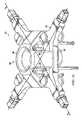
Figures 10-11 in the drawings, a rotor-hub not in accordance with the present invention having a hub-spring 85 comprising two connectingshells 86 is illustrated. As illustrated inFigure 10 , rotor-hub 83 is substantially similar to rotor-hub 29 and comprises substantially similar components except that two connectingshells 86 are present within rotor-hub 83. One connectingshell 86 is mounted on the underside ofyoke 87 while another connectingshell 86 is mounted on the upper side ofyoke 87. One important advantage of rotor-hub 83 is connectingshell 86 redundancy. For example, if one of connectingshells 86 is damaged by a ballistic round or fail for any other reason, the remaining connectingshell 86 can continue to function normally. Another important advantage of an embodiment having two connectingshells 86 is the resulting improved distribution of forces being transferred from hub-springs 85 toyoke 87. Similar to the embodiment ofFigures 3-7 , hub-springs 85 allows gimbaling ofyoke 87 with respect to the mast and mast rotation axis 39 (shown inFigure 3A ). Hub-springs 85 also accommodate flapping of rotor-blades 23 (shown inFigure 2 ) and transfers thrust. - An important advantage of the present invention is that, while providing for use of four or more rotor-blades per rotor-hub, the majority of components are compactly packaged substantially within an interior void space between the yoke straps. This arrangement makes the rotor-hubs of the present invention a tougher target for enemy combatants and a less likely target for unintentional debris. Further, the present invention allows for several variations in pitch horn travel. For example, where a connecting shell is only located on the top of a yoke, more space is available for downward pitch horn travel. Similarly, where a connecting shell is only located on the underside of a yoke more space is available for upward pitch horn travel. Also, where connecting shells are located both on the top and underside of a yoke, pitch horn travel may be more evenly divided between upward travel and downward travel. Finally, for each of the embodiments described above, a CF bearing failure would generally not result in losing a rotor-blade. Rather, the pitch horn associated with the failed CF bearing would be drawn toward the associated crotch of the yoke, such that, at least temporarily, safe operation of the aircraft could occur.
- It is apparent that an invention with significant advantages has been described and illustrated. Although the present invention is shown in a limited number of forms, it is not limited to just these forms, but is amenable to various changes and modifications without departing from the scope thereof.
Claims (18)
- A rotor hub for a rotary wing aircraft, comprising:a yoke (31) having a plurality of yoke arms (33), adjacent yoke arms (33) being joined together by a yoke strap (35), the yoke arms (33) and the yoke straps (35) defining a central void space (30), the void space (30) being adapted to receive a central shaft therethrough;at least one pitch horn (53) having a pitch horn inboard beam (57) and a pitch horn arm (55), wherein the pitch horn (53) is pivotally connected to the yoke (31) and the pitch horn inboard beam (57) is substantially disposed within the central void space (30);a constant velocity joint adapted to transfer force from the central shaft to the yoke (31) and wherein the constant velocity joint is substantially disposed within a central void column (30), characterized in that the rotor hub further comprises:drive links (67) with one end of each drive link (67) connected to a trunnion splined to the central shaft and the other end of each drive link (67) attached to drive legs (68) of an upper outer connecting shell (49) so as to transfer the rotational force from the drive links (67) to the upper outer connecting shell (49), the upper outer connecting shell (49) being connected to the yoke (31) along the yoke straps (35) so as to transfer the rotational force only via the upper outer connecting shell (49) to the yoke (31).
- The rotor hub according to claim 1, wherein the yoke (31) is constructed of discrete layers of directional fiber material.
- The rotor hub according to claim 1, further comprising:a hub spring having the upper outer connecting shell (49) resiliently-attached to the yoke (31).
- The rotor hub according to claim 3, further comprising:a second hub spring having a second outer connecting shell resiliently attached to the yoke (31).
- The rotor hub according to claim 1, wherein the drive links (67) are substantially disposed within the central void space (30).
- The rotor hub according to claim 1, wherein the pitch horns (53) are configured to produce a δ3 angle of about -15 degrees.
- The rotor hub according to claim 1, wherein the yoke (31) is configured to accommodate at least four rotor blades (23).
- The rotor hub according to claim 1, wherein the rotor hub is configured for use with a tiltrotor aircraft (11).
- The rotor hub according to claim 1, comprising:a yoke (31) having at least four yoke arms (33), each pair of adjacent yoke arms (33) being joined together by the yoke strap (35), the yoke arms (33) and the yoke straps (35) defining the central void space (30), the central void space (30) being adapted to receive the central shaft therethrough; andwherein the pitch horns (53) are configured to produce a δ3 angle of about -15 degrees.
- The rotor hub according to claim 9, wherein the yoke (31) is formed from a composite material constructed of discrete layers of directional fibers.
- The rotor hub according to claim 9, further comprising:a first hub spring (45) resiliently coupled to the yoke (31).
- The rotor hub according to claim 11, further comprising:a second hub spring resiliently coupled to the yoke (31).
- A rotary wing aircraft, comprising:a fuselage;at least one engine carried by the fuselage for providing torque;at least one rotary wing member (15, 17);a central shaft for transmitting the torque to the rotary wing member (15, 17); anda rotor hub according to claim 1, the rotor hub being coupled between the central shaft and the rotary wing member (15, 17), the rotor hub further comprising:a first hub spring (45) comprising the connecting shell (49) is fixedly attached to the yoke (31).
- The rotary wing craft according to claim 13, wherein the yoke (31) is constructed of discrete layers of directional fiber material.
- The rotary wing craft according to claim 13, further comprising:a second hub spring comprising a second outer connecting shell, wherein the second outer connecting shell is fixedly attached to the yoke (31).
- The rotary wing craft according to claim 13, wherein the pitch horn (53) is adapted to produce a δ3 angle of about -15 degrees.
- The rotary wing craft according to claim 13, wherein the yoke (31) is operably associated with at least four rotor blades (23).
- The rotary wing craft according to claim 13, wherein the rotary wing craft is a tilt-rotor craft (11).
Applications Claiming Priority (1)
| Application Number | Priority Date | Filing Date | Title |
|---|---|---|---|
| PCT/US2006/001082 WO2007081337A2 (en) | 2006-01-13 | 2006-01-13 | Stiff-in-plane gimbaled tiltrotor hub |
Publications (3)
| Publication Number | Publication Date |
|---|---|
| EP1971521A2 EP1971521A2 (en) | 2008-09-24 |
| EP1971521A4 EP1971521A4 (en) | 2011-06-01 |
| EP1971521B1 true EP1971521B1 (en) | 2012-11-07 |
Family
ID=38256747
Family Applications (1)
| Application Number | Title | Priority Date | Filing Date |
|---|---|---|---|
| EP06849210A Expired - Lifetime EP1971521B1 (en) | 2006-01-13 | 2006-01-13 | Stiff-in-plane gimbaled tiltrotor hub |
Country Status (10)
| Country | Link |
|---|---|
| US (1) | US8257051B2 (en) |
| EP (1) | EP1971521B1 (en) |
| JP (1) | JP2009526680A (en) |
| CN (1) | CN101583535B (en) |
| AU (1) | AU2006335340A1 (en) |
| BR (1) | BRPI0620973A2 (en) |
| CA (1) | CA2635672C (en) |
| DE (1) | DE06849210T1 (en) |
| EA (1) | EA014651B1 (en) |
| WO (1) | WO2007081337A2 (en) |
Families Citing this family (26)
| Publication number | Priority date | Publication date | Assignee | Title |
|---|---|---|---|---|
| WO2010082936A1 (en) * | 2009-01-19 | 2010-07-22 | Bell Helicopter Textron Inc. | Stiff-in-plane rotor configuration |
| WO2011007850A1 (en) * | 2009-07-14 | 2011-01-20 | 豊和鋳機株式会社 | Rotor head |
| GB2472451B (en) * | 2009-08-07 | 2014-06-25 | Christopher Jarvis | Rotor assembly for a rotocraft |
| KR101074988B1 (en) | 2009-10-06 | 2011-10-18 | 한국항공우주산업 주식회사 | Device for measuring angle of rotor blade |
| CN101954970B (en) * | 2010-09-09 | 2013-04-03 | 西北工业大学 | Ventilating propeller hub of propeller tip jet helicopter |
| US9327832B2 (en) | 2011-10-03 | 2016-05-03 | Bell Helicopter Textron Inc. | Elastomeric bearing with tapered shims |
| ITRM20110563A1 (en) * | 2011-10-27 | 2013-04-28 | K4A S R L | "HOMOCINETIC CARDANIC JOINT FOR HELICOPTER ROTORS" |
| US9657582B2 (en) | 2013-03-13 | 2017-05-23 | Bell Helicopter Textron Inc. | Gimbaled tail rotor hub with spherical elastomeric centrifugal force bearing for blade retention and pitch change articulation |
| US10336444B2 (en) * | 2013-08-28 | 2019-07-02 | Sikorsky Aircraft Corporation | Composite stiffened rigid propeller shaped main rotor hub |
| US9334048B2 (en) * | 2013-09-18 | 2016-05-10 | Bell Helicopter Textron Inc. | Elastomeric bearing having tapered layers |
| US9701403B2 (en) * | 2014-02-18 | 2017-07-11 | Bell Helicopter Textron Inc. | Broad goods composite yoke for rotor system |
| US9764831B2 (en) | 2014-03-10 | 2017-09-19 | Bell Helicopter Textron Inc. | Articulated main rotor hub with inwardly CF bearing and 3% flapping hinge offset |
| US10752347B2 (en) | 2014-08-20 | 2020-08-25 | Sikorsky Aircraft Corporation | Rotor blade pitch horn assembly |
| FR3031497B1 (en) | 2015-01-08 | 2017-01-06 | Airbus Helicopters | ROTOR OF GIRAVION COMPRISING A HUB IN COMPOSITE MATERIALS FROM CARBON FIBER TISSUES POWDERED WITH A THERMOPLASTIC RESIN |
| US10443208B2 (en) | 2015-11-18 | 2019-10-15 | Vermeer Manufacturing Company | Pivotally flexible mounting interface for a rotatable shaft |
| US10472057B2 (en) | 2016-02-16 | 2019-11-12 | Bell Helicopter Textron Inc. | Rotor assembly with high lock-number blades |
| US10457388B2 (en) | 2016-02-16 | 2019-10-29 | Bell Helicopter Textron, Inc. | Rotor assembly with high lock-number blades |
| EP3216695B1 (en) * | 2016-02-16 | 2019-06-19 | Bell Helicopter Textron Inc. | Rotor assembly with high lock-number blades |
| CN106347658B (en) * | 2016-09-28 | 2019-05-17 | 深圳智航无人机有限公司 | A kind of unmanned plane of wing adjustable angle |
| US10486805B2 (en) * | 2016-10-19 | 2019-11-26 | Sikorsky Aircraft Corporation | Rotor blade control horn arrangements |
| US10569870B2 (en) * | 2016-11-18 | 2020-02-25 | Textron Innovations Inc. | Proprotor systems for tiltrotor aircraft |
| US20180327086A1 (en) * | 2017-05-13 | 2018-11-15 | Bell Helicopter Textron Inc. | Gimbaled Rotor Hub Assembly with Spherical Bearing |
| US10343772B2 (en) * | 2017-07-10 | 2019-07-09 | Bell Helicopter Textron Inc. | Pitch horn assembly |
| US10960969B2 (en) * | 2018-10-24 | 2021-03-30 | Bell Helicopter Textron Inc. | Method of improving a stability speed of a tiltrotor aircraft |
| US11053001B2 (en) * | 2019-06-20 | 2021-07-06 | Bell Textron Inc. | Low-drag fairing and rotor assembly |
| CN115675857A (en) * | 2022-11-18 | 2023-02-03 | 中国直升机设计研究所 | Electronically controlled pitch rotor system with anti-ballistic capability |
Family Cites Families (19)
| Publication number | Priority date | Publication date | Assignee | Title |
|---|---|---|---|---|
| US2633925A (en) * | 1946-09-20 | 1953-04-07 | Sperry Corp | Rotor hub mounting for a rotary wing aircraft |
| GB2007176B (en) * | 1977-09-07 | 1982-01-06 | Westland Aircraft Ltd | Helicopters |
| US4323332A (en) * | 1979-12-21 | 1982-04-06 | United Technologies Corporation | Hingeless helicopter rotor with elastic gimbal hub |
| US4545733A (en) * | 1982-03-18 | 1985-10-08 | Messerschmitt-Boelkow-Blohm Gesellschaft Mit Beschraenkter Haftung | Apparatus for adjusting the tracking of the blades in a rotor, especially for a rotary wing aircraft |
| IT1159375B (en) * | 1983-04-07 | 1987-02-25 | Agusta Aeronaut Costr | HELICOPTER ROTOR |
| JPS6121894A (en) * | 1984-07-10 | 1986-01-30 | 防衛庁技術研究本部長 | Jointless hub structure for rotor blade aircraft |
| US4580945A (en) * | 1984-09-27 | 1986-04-08 | United Technologies Corporation | Helicopter gimbal rotor |
| US4804352A (en) * | 1987-01-30 | 1989-02-14 | Lord Corporation | Link-type rotary coupling |
| US5059094A (en) * | 1989-10-13 | 1991-10-22 | Bell Helicopter Textron, Inc. | Rotor redundant force retention system for vtol and vstol aircraft |
| IT1240177B (en) * | 1990-04-06 | 1993-11-27 | Agusta Spa | MAIN ROTOR FOR HELICOPTERS |
| ES2126600T3 (en) * | 1991-08-02 | 1999-04-01 | Boeing Co | FAIRED FAN AND PASSAGE CONTROLS FOR THE TAIL ROTOR OF A ROTATING WING AIRCRAFT. |
| US5620305A (en) * | 1995-03-20 | 1997-04-15 | The Boeing Company | Hub for rotary wing aircraft |
| FR2760425B1 (en) * | 1997-03-06 | 2000-08-04 | Rene Mouille | HUB FOR AN AIRCRAFT ROTOR HEAD WITH A TURNING WING AND ROTOR HEAD COMPRISING SUCH A HUB |
| RU2156208C1 (en) * | 1999-04-14 | 2000-09-20 | Любимов Александр Александрович | Helicopter column |
| US6296444B1 (en) * | 1999-10-01 | 2001-10-02 | Bell Helicopter Textron Inc. | Prop rotor hub |
| DE02764289T1 (en) * | 2001-04-19 | 2004-09-30 | Bell Helicopter Textron, Inc., Fort Worth | ROTOR SYSTEM VIBRATION |
| FR2837784B1 (en) | 2002-03-28 | 2004-05-28 | Eurocopter France | CELLULAR DRIVE ROTOR ROTOR WITH TORQUE SHARING DIFFERENTIAL |
| RU2235662C2 (en) * | 2002-08-12 | 2004-09-10 | Открытое акционерное общество "Иркутское авиационное производственное объединение" | Main-rotor hub |
| US6981844B2 (en) * | 2003-10-08 | 2006-01-03 | Hamilton Sundstrand | Cyclic actuation system for a controllable pitch propeller and a method of providing aircraft control therewith |
-
2006
- 2006-01-13 CN CN200680050896.8A patent/CN101583535B/en not_active Expired - Fee Related
- 2006-01-13 DE DE06849210T patent/DE06849210T1/en active Pending
- 2006-01-13 BR BRPI0620973-4A patent/BRPI0620973A2/en not_active IP Right Cessation
- 2006-01-13 US US12/159,007 patent/US8257051B2/en not_active Expired - Fee Related
- 2006-01-13 EP EP06849210A patent/EP1971521B1/en not_active Expired - Lifetime
- 2006-01-13 CA CA2635672A patent/CA2635672C/en not_active Expired - Lifetime
- 2006-01-13 JP JP2008550277A patent/JP2009526680A/en active Pending
- 2006-01-13 EA EA200801544A patent/EA014651B1/en not_active IP Right Cessation
- 2006-01-13 WO PCT/US2006/001082 patent/WO2007081337A2/en not_active Ceased
- 2006-01-13 AU AU2006335340A patent/AU2006335340A1/en not_active Abandoned
Also Published As
| Publication number | Publication date |
|---|---|
| US20080292468A1 (en) | 2008-11-27 |
| EA014651B1 (en) | 2010-12-30 |
| WO2007081337A2 (en) | 2007-07-19 |
| EP1971521A2 (en) | 2008-09-24 |
| US8257051B2 (en) | 2012-09-04 |
| CA2635672C (en) | 2012-06-12 |
| WO2007081337A9 (en) | 2007-09-07 |
| DE06849210T1 (en) | 2009-01-29 |
| CN101583535A (en) | 2009-11-18 |
| CN101583535B (en) | 2013-11-06 |
| BRPI0620973A2 (en) | 2011-11-29 |
| EP1971521A4 (en) | 2011-06-01 |
| CA2635672A1 (en) | 2007-07-19 |
| JP2009526680A (en) | 2009-07-23 |
| AU2006335340A1 (en) | 2007-07-19 |
| WO2007081337A3 (en) | 2009-06-04 |
| EA200801544A1 (en) | 2009-02-27 |
Similar Documents
| Publication | Publication Date | Title |
|---|---|---|
| CA2635672C (en) | Stiff-in-plane gimbaled tiltrotor hub | |
| US10392098B2 (en) | High stiffness hub assemblies for rotor systems | |
| US4093400A (en) | Cross beam rotor | |
| US7264199B2 (en) | Unloaded lift offset rotor system for a helicopter | |
| EP2778062B1 (en) | Gimbaled tail rotor hub with elastomeric centrifugal force bearing for blade retention and pitch change articulation | |
| US8360721B2 (en) | Low maintenance stiff in plane gimbaled rotor head | |
| US10472057B2 (en) | Rotor assembly with high lock-number blades | |
| EP1238906B1 (en) | Multi-bladed tail rotor hub design for Coriolis relief | |
| EP2657130B1 (en) | Aircraft rotor with discrete flap hinge | |
| EP2868576B1 (en) | Drive link for tiltrotor rotor system | |
| US11136116B2 (en) | Elastomeric double Hooke's joint | |
| US8128034B2 (en) | Rotorcraft with opposing roll mast moments, and related methods | |
| US6439849B1 (en) | Dual trunnion hub-to-mast assembly | |
| EP3446972B1 (en) | Low moment rotor hub | |
| EP3575211B1 (en) | Rotor assembly with high lock-number blades | |
| US20180327086A1 (en) | Gimbaled Rotor Hub Assembly with Spherical Bearing | |
| EP3216695B1 (en) | Rotor assembly with high lock-number blades | |
| MX2008009001A (en) | Stiff-in-plane gimbaled tiltrotor hub | |
| CA2995295C (en) | Rotor assembly with high lock-number blades | |
| WO2025132911A1 (en) | Aircraft rotor assembly and aircraft | |
| KR20080094035A (en) | In-plane rigid gimbal tilt rotor hub |
Legal Events
| Date | Code | Title | Description |
|---|---|---|---|
| PUAI | Public reference made under article 153(3) epc to a published international application that has entered the european phase |
Free format text: ORIGINAL CODE: 0009012 |
|
| 17P | Request for examination filed |
Effective date: 20080730 |
|
| AK | Designated contracting states |
Kind code of ref document: A2 Designated state(s): AT BE BG CH CY CZ DE DK EE ES FI FR GB GR HU IE IS IT LI LT LU LV MC NL PL PT RO SE SI SK TR |
|
| AX | Request for extension of the european patent |
Extension state: AL BA HR MK YU |
|
| RIN1 | Information on inventor provided before grant (corrected) |
Inventor name: STAMPS, FRANK, B. Inventor name: WASIKOWSKI, MARK Inventor name: TISDALE, PATRICK, R. Inventor name: CAMPBELL, THOMAS, C. Inventor name: RAUBER, RICHARD, E. Inventor name: BRASWELL, JAMES, L., JR. Inventor name: POPELKA, DAVID, A. Inventor name: SOUTHERLAND, MICHAEL, J. Inventor name: STANNEY, KEITH |
|
| EL | Fr: translation of claims filed | ||
| DET | De: translation of patent claims | ||
| R17D | Deferred search report published (corrected) |
Effective date: 20090604 |
|
| RIC1 | Information provided on ipc code assigned before grant |
Ipc: B64C 27/48 20060101AFI20090605BHEP |
|
| DAX | Request for extension of the european patent (deleted) | ||
| RBV | Designated contracting states (corrected) |
Designated state(s): DE FR GB IT |
|
| A4 | Supplementary search report drawn up and despatched |
Effective date: 20110504 |
|
| GRAP | Despatch of communication of intention to grant a patent |
Free format text: ORIGINAL CODE: EPIDOSNIGR1 |
|
| RIN1 | Information on inventor provided before grant (corrected) |
Inventor name: CAMPBELL, THOMAS, C. Inventor name: STAMPS, FRANK, B. Inventor name: SOUTHERLAND, MICHAEL, J. Inventor name: TISDALE, PATRICK, R. Inventor name: RAUBER, RICHARD, E. Inventor name: POPELKA, DAVID, A. Inventor name: WASIKOWSKI, MARK Inventor name: STANNEY, KEITH Inventor name: BRASWELL, JAMES, L., JR. |
|
| GRAS | Grant fee paid |
Free format text: ORIGINAL CODE: EPIDOSNIGR3 |
|
| GRAA | (expected) grant |
Free format text: ORIGINAL CODE: 0009210 |
|
| AK | Designated contracting states |
Kind code of ref document: B1 Designated state(s): DE FR GB IT |
|
| REG | Reference to a national code |
Ref country code: GB Ref legal event code: FG4D |
|
| REG | Reference to a national code |
Ref country code: DE Ref legal event code: R096 Ref document number: 602006032982 Country of ref document: DE Effective date: 20130103 |
|
| PLBE | No opposition filed within time limit |
Free format text: ORIGINAL CODE: 0009261 |
|
| STAA | Information on the status of an ep patent application or granted ep patent |
Free format text: STATUS: NO OPPOSITION FILED WITHIN TIME LIMIT |
|
| 26N | No opposition filed |
Effective date: 20130808 |
|
| REG | Reference to a national code |
Ref country code: DE Ref legal event code: R097 Ref document number: 602006032982 Country of ref document: DE Effective date: 20130808 |
|
| REG | Reference to a national code |
Ref country code: FR Ref legal event code: PLFP Year of fee payment: 11 |
|
| REG | Reference to a national code |
Ref country code: FR Ref legal event code: PLFP Year of fee payment: 12 |
|
| REG | Reference to a national code |
Ref country code: FR Ref legal event code: PLFP Year of fee payment: 13 |
|
| PGFP | Annual fee paid to national office [announced via postgrant information from national office to epo] |
Ref country code: GB Payment date: 20230127 Year of fee payment: 18 Ref country code: DE Payment date: 20230127 Year of fee payment: 18 |
|
| PGFP | Annual fee paid to national office [announced via postgrant information from national office to epo] |
Ref country code: IT Payment date: 20240122 Year of fee payment: 19 Ref country code: FR Payment date: 20240125 Year of fee payment: 19 |
|
| REG | Reference to a national code |
Ref country code: DE Ref legal event code: R119 Ref document number: 602006032982 Country of ref document: DE |
|
| GBPC | Gb: european patent ceased through non-payment of renewal fee |
Effective date: 20240113 |
|
| PG25 | Lapsed in a contracting state [announced via postgrant information from national office to epo] |
Ref country code: DE Free format text: LAPSE BECAUSE OF NON-PAYMENT OF DUE FEES Effective date: 20240801 |
|
| PG25 | Lapsed in a contracting state [announced via postgrant information from national office to epo] |
Ref country code: GB Free format text: LAPSE BECAUSE OF NON-PAYMENT OF DUE FEES Effective date: 20240113 |
|
| PG25 | Lapsed in a contracting state [announced via postgrant information from national office to epo] |
Ref country code: GB Free format text: LAPSE BECAUSE OF NON-PAYMENT OF DUE FEES Effective date: 20240113 Ref country code: DE Free format text: LAPSE BECAUSE OF NON-PAYMENT OF DUE FEES Effective date: 20240801 |
|
| PG25 | Lapsed in a contracting state [announced via postgrant information from national office to epo] |
Ref country code: FR Free format text: LAPSE BECAUSE OF NON-PAYMENT OF DUE FEES Effective date: 20250131 |
|
| PG25 | Lapsed in a contracting state [announced via postgrant information from national office to epo] |
Ref country code: IT Free format text: LAPSE BECAUSE OF NON-PAYMENT OF DUE FEES Effective date: 20250113 |