EP1970686B1 - Pressure sensor and manufacturing method of said sensor - Google Patents
Pressure sensor and manufacturing method of said sensor Download PDFInfo
- Publication number
- EP1970686B1 EP1970686B1 EP08152807A EP08152807A EP1970686B1 EP 1970686 B1 EP1970686 B1 EP 1970686B1 EP 08152807 A EP08152807 A EP 08152807A EP 08152807 A EP08152807 A EP 08152807A EP 1970686 B1 EP1970686 B1 EP 1970686B1
- Authority
- EP
- European Patent Office
- Prior art keywords
- flexible board
- cap
- circuit board
- pressure sensor
- belt portion
- Prior art date
- Legal status (The legal status is an assumption and is not a legal conclusion. Google has not performed a legal analysis and makes no representation as to the accuracy of the status listed.)
- Not-in-force
Links
- 238000004519 manufacturing process Methods 0.000 title claims description 6
- 238000000034 method Methods 0.000 claims description 10
- 238000005452 bending Methods 0.000 claims description 3
- 230000008569 process Effects 0.000 description 6
- RYGMFSIKBFXOCR-UHFFFAOYSA-N Copper Chemical compound [Cu] RYGMFSIKBFXOCR-UHFFFAOYSA-N 0.000 description 4
- 229910052802 copper Inorganic materials 0.000 description 4
- 239000010949 copper Substances 0.000 description 4
- 239000012530 fluid Substances 0.000 description 4
- 238000003466 welding Methods 0.000 description 4
- 239000002184 metal Substances 0.000 description 3
- 229910052751 metal Inorganic materials 0.000 description 3
- 230000004308 accommodation Effects 0.000 description 2
- 230000001154 acute effect Effects 0.000 description 2
- 230000015572 biosynthetic process Effects 0.000 description 2
- 238000002788 crimping Methods 0.000 description 2
- 230000002708 enhancing effect Effects 0.000 description 2
- 238000003825 pressing Methods 0.000 description 2
- 230000009467 reduction Effects 0.000 description 2
- 238000005476 soldering Methods 0.000 description 2
- 230000006978 adaptation Effects 0.000 description 1
- 230000008859 change Effects 0.000 description 1
- 238000004891 communication Methods 0.000 description 1
- 230000008878 coupling Effects 0.000 description 1
- 238000010168 coupling process Methods 0.000 description 1
- 238000005859 coupling reaction Methods 0.000 description 1
- 238000010894 electron beam technology Methods 0.000 description 1
- PCHJSUWPFVWCPO-UHFFFAOYSA-N gold Chemical compound [Au] PCHJSUWPFVWCPO-UHFFFAOYSA-N 0.000 description 1
- 230000004048 modification Effects 0.000 description 1
- 238000012986 modification Methods 0.000 description 1
- 230000035699 permeability Effects 0.000 description 1
- 229920003002 synthetic resin Polymers 0.000 description 1
- 239000000057 synthetic resin Substances 0.000 description 1
- XLYOFNOQVPJJNP-UHFFFAOYSA-N water Substances O XLYOFNOQVPJJNP-UHFFFAOYSA-N 0.000 description 1
Images


Classifications
-
- G—PHYSICS
- G01—MEASURING; TESTING
- G01L—MEASURING FORCE, STRESS, TORQUE, WORK, MECHANICAL POWER, MECHANICAL EFFICIENCY, OR FLUID PRESSURE
- G01L9/00—Measuring steady of quasi-steady pressure of fluid or fluent solid material by electric or magnetic pressure-sensitive elements; Transmitting or indicating the displacement of mechanical pressure-sensitive elements, used to measure the steady or quasi-steady pressure of a fluid or fluent solid material, by electric or magnetic means
- G01L9/0041—Transmitting or indicating the displacement of flexible diaphragms
- G01L9/0051—Transmitting or indicating the displacement of flexible diaphragms using variations in ohmic resistance
-
- G—PHYSICS
- G01—MEASURING; TESTING
- G01L—MEASURING FORCE, STRESS, TORQUE, WORK, MECHANICAL POWER, MECHANICAL EFFICIENCY, OR FLUID PRESSURE
- G01L19/00—Details of, or accessories for, apparatus for measuring steady or quasi-steady pressure of a fluent medium insofar as such details or accessories are not special to particular types of pressure gauges
- G01L19/0061—Electrical connection means
-
- G—PHYSICS
- G01—MEASURING; TESTING
- G01L—MEASURING FORCE, STRESS, TORQUE, WORK, MECHANICAL POWER, MECHANICAL EFFICIENCY, OR FLUID PRESSURE
- G01L19/00—Details of, or accessories for, apparatus for measuring steady or quasi-steady pressure of a fluent medium insofar as such details or accessories are not special to particular types of pressure gauges
- G01L19/14—Housings
- G01L19/148—Details about the circuit board integration, e.g. integrated with the diaphragm surface or encapsulation
-
- H—ELECTRICITY
- H05—ELECTRIC TECHNIQUES NOT OTHERWISE PROVIDED FOR
- H05K—PRINTED CIRCUITS; CASINGS OR CONSTRUCTIONAL DETAILS OF ELECTRIC APPARATUS; MANUFACTURE OF ASSEMBLAGES OF ELECTRICAL COMPONENTS
- H05K1/00—Printed circuits
- H05K1/02—Details
- H05K1/14—Structural association of two or more printed circuits
- H05K1/147—Structural association of two or more printed circuits at least one of the printed circuits being bent or folded, e.g. by using a flexible printed circuit
-
- H—ELECTRICITY
- H05—ELECTRIC TECHNIQUES NOT OTHERWISE PROVIDED FOR
- H05K—PRINTED CIRCUITS; CASINGS OR CONSTRUCTIONAL DETAILS OF ELECTRIC APPARATUS; MANUFACTURE OF ASSEMBLAGES OF ELECTRICAL COMPONENTS
- H05K1/00—Printed circuits
- H05K1/02—Details
- H05K1/11—Printed elements for providing electric connections to or between printed circuits
- H05K1/118—Printed elements for providing electric connections to or between printed circuits specially for flexible printed circuits, e.g. using folded portions
-
- H—ELECTRICITY
- H05—ELECTRIC TECHNIQUES NOT OTHERWISE PROVIDED FOR
- H05K—PRINTED CIRCUITS; CASINGS OR CONSTRUCTIONAL DETAILS OF ELECTRIC APPARATUS; MANUFACTURE OF ASSEMBLAGES OF ELECTRICAL COMPONENTS
- H05K2201/00—Indexing scheme relating to printed circuits covered by H05K1/00
- H05K2201/09—Shape and layout
- H05K2201/09009—Substrate related
- H05K2201/09063—Holes or slots in insulating substrate not used for electrical connections
-
- H—ELECTRICITY
- H05—ELECTRIC TECHNIQUES NOT OTHERWISE PROVIDED FOR
- H05K—PRINTED CIRCUITS; CASINGS OR CONSTRUCTIONAL DETAILS OF ELECTRIC APPARATUS; MANUFACTURE OF ASSEMBLAGES OF ELECTRICAL COMPONENTS
- H05K2201/00—Indexing scheme relating to printed circuits covered by H05K1/00
- H05K2201/09—Shape and layout
- H05K2201/09209—Shape and layout details of conductors
- H05K2201/09372—Pads and lands
- H05K2201/0949—Pad close to a hole, not surrounding the hole
-
- H—ELECTRICITY
- H05—ELECTRIC TECHNIQUES NOT OTHERWISE PROVIDED FOR
- H05K—PRINTED CIRCUITS; CASINGS OR CONSTRUCTIONAL DETAILS OF ELECTRIC APPARATUS; MANUFACTURE OF ASSEMBLAGES OF ELECTRICAL COMPONENTS
- H05K2201/00—Indexing scheme relating to printed circuits covered by H05K1/00
- H05K2201/10—Details of components or other objects attached to or integrated in a printed circuit board
- H05K2201/10007—Types of components
- H05K2201/10151—Sensor
-
- H—ELECTRICITY
- H05—ELECTRIC TECHNIQUES NOT OTHERWISE PROVIDED FOR
- H05K—PRINTED CIRCUITS; CASINGS OR CONSTRUCTIONAL DETAILS OF ELECTRIC APPARATUS; MANUFACTURE OF ASSEMBLAGES OF ELECTRICAL COMPONENTS
- H05K2203/00—Indexing scheme relating to apparatus or processes for manufacturing printed circuits covered by H05K3/00
- H05K2203/04—Soldering or other types of metallurgic bonding
- H05K2203/049—Wire bonding
-
- H—ELECTRICITY
- H05—ELECTRIC TECHNIQUES NOT OTHERWISE PROVIDED FOR
- H05K—PRINTED CIRCUITS; CASINGS OR CONSTRUCTIONAL DETAILS OF ELECTRIC APPARATUS; MANUFACTURE OF ASSEMBLAGES OF ELECTRICAL COMPONENTS
- H05K3/00—Apparatus or processes for manufacturing printed circuits
- H05K3/30—Assembling printed circuits with electric components, e.g. with resistor
- H05K3/306—Lead-in-hole components, e.g. affixing or retention before soldering, spacing means
-
- Y—GENERAL TAGGING OF NEW TECHNOLOGICAL DEVELOPMENTS; GENERAL TAGGING OF CROSS-SECTIONAL TECHNOLOGIES SPANNING OVER SEVERAL SECTIONS OF THE IPC; TECHNICAL SUBJECTS COVERED BY FORMER USPC CROSS-REFERENCE ART COLLECTIONS [XRACs] AND DIGESTS
- Y10—TECHNICAL SUBJECTS COVERED BY FORMER USPC
- Y10T—TECHNICAL SUBJECTS COVERED BY FORMER US CLASSIFICATION
- Y10T29/00—Metal working
- Y10T29/49—Method of mechanical manufacture
- Y10T29/49002—Electrical device making
- Y10T29/49082—Resistor making
Definitions
- the present invention relates to a pressure sensor having a sensor element and a flexible board with an end connected to a measuring portion of the sensor element, and a manufacturing method of sensor.
- a pressure sensor for measuring fluid pressure has been known as one of those sensors that measure physical quantities.
- a conventional example of such a pressure sensor includes: a pressure-sensitive element attached to an end of a pipe; a circuit board; and a flexible board having an end connected to the pressure-sensitive element and the other end connected to the circuit board (document: JP-A-2005-326337 ).
- the flexible board is employed for transmitting a signal of the pressure-sensitive element to the circuit board.
- the flexible board is bent for accommodating within the pipe.
- the flexible board of the conventional example disclosed in the above-mentioned document is bent for accommodating within the pipe
- copper pattern provided on the flexible board may be cracked or otherwise damaged when the flexible board is bent for accommodating within the pipe.
- the bending angle of the flexible print board has to be increased, which requires a large accommodation space for the flexible board.
- An object of the invention is to provide a pressure sensor that does not cause damage on a flexible board when the flexible board is bent to be accommodated and is capable of accommodating the flexible board with a compact space, and a manufacturing method of the pressure sensor.
- a pressure sensor includes: a sensor element having a measuring portion; a cap provided on the measuring portion of the sensor element; a circuit board; and a flexible board, wherein the flexible board has a first end connected to a flat side of the cap, a belt portion provided in a planar C-shape including a short section connected to the first end and bent away from the circuit board at an angle of ninety degrees or more relative to the first end, a connector portion connected at a right angle to the short section and a long section connected to the connector portion at a right angle, the connector portion being curved along an outer circumference of the sensor element, and a second end that is bent at an angle of ninety degrees or more relative to the belt portion to be connected with the circuit board.
- the flexible board since it is only necessary that the first end and the second end are bent at an angle of ninety degrees or more relative to the belt portion, the flexible board is not locally bent by an acute angle. Accordingly, no crack is generated on the electro-conductive portion provided on the flexible board, e.g. wiring pattern.
- the flexible board since the flexible board is bent along the outer circumference of the sensor element, the flexible board is bent by a minimum required angle within a narrow space, thus reducing the accommodation space of the flexible board.
- a periphery of the belt portion does not protrude from the flat side of the cap.
- the belt portion since the belt portion does not protrude from the flat side of the cap, the belt portion does not impede bonding process of the second end to the circuit board. Accordingly, the bonding process of the flexible board can be easily conducted.
- the senor element is bonded to a joint, a block having an inner circumference spaced away from the outer circumference of the sensor element by a predetermined gap is bonded to the joint and the circuit board is attached to the block.
- a bonding pad that constitutes a part of a first wiring pattern is provided on the first end of the flexible board at a side remote from the cap, and a support pad having the same shape as the bonding pad is provided on the first end of the flexible board on a side facing the cap at a position corresponding to the bonding pad.
- the support pad having the same shape as the bonding pad is provided on an opposite side of the flexible board sandwiching the first end, so that the first end of the flexible board is not tilted or deformed, thus securing flatness of the first end of the flexible board.
- the wire-bonding between the bonding pad and the sensor element can be securely conducted, thus further enhancing the bonding strength therebetween.
- a planar area of the support pad is larger than a planar area of the bonding pad.
- a second wiring pattern is provided on a side of the flexible board facing the cap, and a part of the second wiring pattern is constituted by the support pad.
- the support pad can be formed simultaneously with the formation of the wiring pattern.
- the flexible board can be easily manufactured.
- a method according to another aspect of the invention is for manufacturing the pressure sensor, the method including: attaching the cap on the sensor element; connecting the first end of the flexible board to the cap; bending the belt portion by an angle of ninety degrees or more relative to the first end to be curved along the outer circumference of the sensor element; and bonding the second end to the circuit board, wherein the second end is bent relative to the belt portion.
- the manufacturing method for a sensor that can exhibit the same advantages as in the above can be provided.
- Fig. 1 is a cross section of a pressure sensor of the exemplary embodiment.
- the pressure sensor 1 is provided with: a joint 10 having a flange 10A at an intermediate position thereof; a diaphragm 11 (sensor element) provided on a first end of the joint 10; a block 12 provided on the flange 10A of the joint 10; a housing 13 and a circuit board 14 respectively provided on the block 12; a flexible board 15 connected to the circuit board 14 and the diaphragm 11; and a terminal 16 supported by the housing 13.
- the joint 10 is a molded metal component and is provided with a pressure port 10B extending from the first end to a second end opposite thereto.
- a screw 10C to be screwed into a pipe in which to-be-measured fluid is flowed is provided on an outer circumference of the joint 10 on a side adjacent to the second end relative to the flange 10A.
- the diaphragm 11 is provided by a metal component, which includes: a cylindrical member 11A; a disk 11B provided on a first end of the cylindrical member 11A; and a flange 11C provided on an outer circumference of the cylindrical member 11A, the cylindrical member 11A, the disk 11B and the flange 11C being provided in an integrated manner.
- the to-be-measured fluid is introduced into a recessed space provided inside the cylindrical member 11A and the disk 11B of the diaphragm 11 through the pressure port 10B of the joint 10.
- a measuring portion that detects the pressure by a strain gauge and the like is provided on a side of the disk 11B of the diaphragm 11 opposite to a side on which the to-be-measured fluid is introduced.
- a cap 17 is provided to cover an upper side of the measuring portion. The cap 17 is bonded to be electrically coupled with a first end of the flexible board 15.
- the block 12 is a metal component, which includes an integrated component of a hexagonal portion 12A with a hexagonal outer circumference and a circular portion 12B with a circular outer circumference.
- a cylindrical space 12C for the diaphragm 11 to be disposed penetrates through the inside of the block 12.
- An end of the block 12 on the side of the circular portion 12B is welded to the flange 10A of the joint 10.
- a substantially cylindrical exterior portion 12D is provided on an end of the block 12 on the side of the hexagonal portion 12A.
- the exterior portion 12D is provided for crimping the housing 13.
- An end of the exterior portion 12D is bent toward the axial center of the joint 10 after the housing 13 is attached.
- the housing 13 is a synthetic resin component, which has a substantially bottomed-cylindrical base end 13A and a cylindrical distal end 13B integrated with the base end 13A.
- a periphery of the base end 13A is fitted to the exterior portion l2D of the block 12.
- An O ring 18 is provided between the inner circumference of the exterior portion 12D and the outer circumference of the base end 13A.
- the terminal 16 is held by a disk 13C provided between the base end 13A and the distal end 13B.
- a gap d is provided between the terminal 16 and the disk 13C.
- the gap d is for adjusting the variable pressure within the space surrounded by the joint 10, the diaphragm 11, the block 12 and the housing 13.
- the distal end 13B is adapted to be connected with a connector (not shown).
- An air-vent filter 19 that allows circulation of exterior air is provided on the distal end 13B at a position covered by the connector.
- the air-vent filter 19 satisfies both requirements of waterproof property and air permeability, which is substantially formed in a disk-shape.
- a recess 13D for the air-vent filter 19 to be fitted is provided on the outer circumference of the distal end 13B.
- An air-vent 13E is connected to the recess 13D.
- the circuit board 14 is sized so as to cover the opening of the cylindrical space 12C of the block 12, both ends of which are supported on an end surface of the block 12 with an attachment 14A.
- Electronic components 20 are mounted on the circuit board 14.
- the terminal 16 is bent substantially in an L-shape. A first end 16A of the terminal 16 is supported by the housing 13 while a second end thereof is electrically coupled with the circuit board 14.
- the bent portion of the terminal 16 is fixed on a case 21 that is attached to the end surface of the block 12.
- the flexible board 15 includes a first end 15A of which whole area is connected to the cap 17, a second end 15B connected to the circuit board 14 and a belt portion 15C that connects the first end 15A and the second end 15B.
- the first end 15A is electrically coupled with the diaphragm 11 by a bonding wire.
- the second end 15B is electrically coupled to the circuit board 14 by soldering.
- Figs. 2 and 3 show the flexible board 15 attached to the diaphragm 11.
- Fig. 2 is a perspective view showing the flexible board 15 attached to the diaphragm 11.
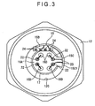
- Fig. 3 is a plan view showing the flexible board 15 attached to the diaphragm 11.
- the first end 15A of the flexible board 15 is formed in a disk having a slightly smaller diameter than that of the disk 11B of the diaphragm 11.
- a plurality (four in the figures) of thin disk bonding pads 22 are circumferentially arrayed on the top side of the first end 15A_ The bonding pads 22 protrude from the top side of the first end 15A.
- a plurality (four in the figures) of holes 15D are provided between the bonding pads.
- the holes 15D are provided for wire bonding between the bonding pads 22 and the diaphragm 11.
- Fig. 4 is an expansion plan view showing the top side of the flexible board 15.
- Fig. 5 is another expansion plan view showing the backside of the flexible board 15.
- Fig. 6 is a cross section taken along VI-VI line in Fig. 4 .
- the belt portion 15C is a C-shaped member viewed in a plan, which includes a short section 15C1 connected to the first end 15A, a connector portion 15C2 connected at a right angle to the short section 15C1 and a long section 15C3 connected to the connector portion 15C2 at a right angle.
- the long section 15C3 is connected with the second end 15B.
- the width of the second end 15B is greater than the width of the long section 15C3.
- two of the bonding pads 22 disposed near the belt portion 15C are respectively connected with ends of two electro-conductive portions 23.
- the electro-conductive portions 23 are formed in a C-shape along the planar shape of the belt portion 15C.
- the other ends of the electro-conductive portions 23 are connected to a part of a plurality (four in the figure) of terminals 24 provided on the second end 15B.
- the bonding pads 22, the electro-conductive portions 23 and the terminals 24 provide a wiring pattern on the top side of the flexible board 15.
- the wiring pattern is mainly provided by copper.
- FIG. 5 another wiring pattern corresponding to that on the top side is provided on the backside of the flexible board 15.
- support pads 25 having the same shape as the bonding pads 22 are provided on the backside of the first end 15A of the flexible board 15 at positions corresponding to the bonding pads 22.
- two of the support pads 25 disposed near the belt portion 15C are respectively connected with ends of two electro-conductive portions 26 as shown in imaginary lines.
- the electro-conductive portions 26 are formed in a C-shape at a position corresponding to the electro-conductive portion 23.
- the other ends of the electro-conductive portions 26 are connected to a part of a plurality (four in the figure) of terminals 27 provided on the second end 15B.
- Adjoining support pads 25 may be connected by an electro-conductive portion 28.
- the support pads 25, the electro-conductive portions 26, 28 and the terminals 27 provide a wiring pattern on the backside of the flexible board 15.
- the wiring pattern is mainly provided by copper.
- the support pad 25 provided on the backside of the flexible board 15 protrudes from the backside of the first end 15A to be formed in a thin disk. All of the support pads 25 have the same thickness.
- Axial centers of the bonding pads 22 and the support pads 25 substantially coincide with each other.
- the diameter D2 of the support pad 25 is the same as or larger than the diameter D1 of the bonding pad 22.
- the planar area of the support pad 25 is the same as or larger than the planar area of the bonding pad 22.
- a through-hole 15E penetrates through the first end 15A of the flexible board 15 in order to electrically couple the bonding pad 22 and the support pad 25.
- a short section 15C1 of the belt portion 15C is bent at an angle of ninety degrees or more relative to the first end 15A of the flexible board 15 in a direction to go away from the circuit board 14.
- the connector portion 15C2 integrated with the short section 15C1 is disposed in a curved manner along the outer circumference of the diaphragm 11 so that periphery of the connector portion 15C2 on the side of the circuit board 14 does not protrude from the top (flat) side of the cap 17.
- the long section 15C3 integrated with the connector portion 15C2 protrudes from the first end 15A toward the circuit board 14.
- the long section 15C3 and the second end 15B are bent at an angle of ninety degrees or more.
- Fig. 7 is an illustration showing how the flexible board is bonded to the cap.
- the diaphragm 11 is airtightly connected to the joint 10 by electron beam welding.
- the first end 15A of the flexible board 15 and the cap 17 are thermocompression-bonded by an adhesion sheet 29 (see Fig, 7 ).
- an adhesion sheet 29 see Fig, 7 .
- a force for pressing the first end 15A, toward the cap 17 is applied.
- the support pad 25 is provided at the same position as the bonding pad 22 in the exemplary embodiment, the first end 15A and the bonding pad 22 are not tilted relative to the top side of the cap 17.
- the cap 17 is laser-welded to the diaphragm 11.
- the diaphragm 1 and the bonding pad 22 provided on the first end 15A of the flexible board 15 are connected by wire bonding using a gold wire.
- the bonding process is conducted by feeding a bonding line from a capillary tube (not shown) to the bonding pad 22. At this time, since the bonding pad 22 is not tilted, bonding operation can be stabilized.
- the block 12 and the joint 10 are airtightly connected by laser-welding.
- the short section 15C1 of the belt portion 15C is bent nearly by ninety degrees relative to the first end 15A of the flexible board 15 and the connector portion 15C2 is curved along the circumference of the diaphragm 11.
- a distal end of the long section 15C3 protrudes relative to the first end 15A.
- the circuit board 14 is fixed on an end surface of the block 12 and the second end 15B of the flexible board 15 is soldered onto the circuit board 14.
- the second end 15B of the flexible board 15 is bent nearly by ninety degrees relative to the long section 15C3.
- the flexible board 15 and the inner circumference of the block 12 are bonded and fixed. After the case 21 is fixed onto the joint 10 by projection-welding, the case 21 and the terminal 16 are crimped. Incidentally, the block 12 and the exterior portion 12D are provided as separate bodies, which are welded after crimping the case 21 and the terminal 16.
- the terminal 16 and the circuit board 14 are connected by precision resistance welding, the housing 13 assembled with the O ring 18 is inserted and the housing 13 is crimped to the block 12.
- the periphery of the belt portion 15C does not protrude from the top side of the cap 17 in the exemplary embodiment, the periphery of the belt portion 15C of the invention may be protruded from the top side of the cap 17.
- the external shape of the block 12 is not limited to hexagon, but may be formed in a cylindrical shape.
- the invention is not applied limitatively to the pressure sensor, but may be applied to a differential-pressure sensor, and the like.
Landscapes
- Physics & Mathematics (AREA)
- General Physics & Mathematics (AREA)
- Engineering & Computer Science (AREA)
- Microelectronics & Electronic Packaging (AREA)
- Measuring Fluid Pressure (AREA)
Abstract
Description
- The present invention relates to a pressure sensor having a sensor element and a flexible board with an end connected to a measuring portion of the sensor element, and a manufacturing method of sensor.
- A pressure sensor for measuring fluid pressure has been known as one of those sensors that measure physical quantities.
- A conventional example of such a pressure sensor includes: a pressure-sensitive element attached to an end of a pipe; a circuit board; and a flexible board having an end connected to the pressure-sensitive element and the other end connected to the circuit board (document:
JP-A-2005-326337 - The flexible board is employed for transmitting a signal of the pressure-sensitive element to the circuit board. In the conventional example disclosed in the above document, the flexible board is bent for accommodating within the pipe.
- Since the flexible board of the conventional example disclosed in the above-mentioned document is bent for accommodating within the pipe, copper pattern provided on the flexible board may be cracked or otherwise damaged when the flexible board is bent for accommodating within the pipe. In order not to cause cracks and the like on the copper pattern, the bending angle of the flexible print board has to be increased, which requires a large accommodation space for the flexible board.
- An object of the invention is to provide a pressure sensor that does not cause damage on a flexible board when the flexible board is bent to be accommodated and is capable of accommodating the flexible board with a compact space, and a manufacturing method of the pressure sensor.
- A pressure sensor according to an aspect of the invention includes: a sensor element having a measuring portion; a cap provided on the measuring portion of the sensor element; a circuit board; and a flexible board, wherein the flexible board has a first end connected to a flat side of the cap, a belt portion provided in a planar C-shape including a short section connected to the first end and bent away from the circuit board at an angle of ninety degrees or more relative to the first end, a connector portion connected at a right angle to the short section and a long section connected to the connector portion at a right angle, the connector portion being curved along an outer circumference of the sensor element, and a second end that is bent at an angle of ninety degrees or more relative to the belt portion to be connected with the circuit board.
- According to the above aspect of the invention, since it is only necessary that the first end and the second end are bent at an angle of ninety degrees or more relative to the belt portion, the flexible board is not locally bent by an acute angle. Accordingly, no crack is generated on the electro-conductive portion provided on the flexible board, e.g. wiring pattern. In addition, since the flexible board is bent along the outer circumference of the sensor element, the flexible board is bent by a minimum required angle within a narrow space, thus reducing the accommodation space of the flexible board.
- In the above aspect of the invention, it is preferable that a periphery of the belt portion does not protrude from the flat side of the cap.
- According to the above arrangement, since the belt portion does not protrude from the flat side of the cap, the belt portion does not impede bonding process of the second end to the circuit board. Accordingly, the bonding process of the flexible board can be easily conducted.
- Further, in the above aspect of the invention, it is preferable that the sensor element is bonded to a joint, a block having an inner circumference spaced away from the outer circumference of the sensor element by a predetermined gap is bonded to the joint and the circuit board is attached to the block.
- According to the above arrangement, since the sensor element attached with the flexible board is housed within the interior space of the block, space reduction can be further enhanced.
- In the above aspect of the invention, it is preferable that a bonding pad that constitutes a part of a first wiring pattern is provided on the first end of the flexible board at a side remote from the cap, and a support pad having the same shape as the bonding pad is provided on the first end of the flexible board on a side facing the cap at a position corresponding to the bonding pad.
- According to the above arrangement, even when a force toward the cap is applied in compression-bonding the first end of the flexible board to the cap, the support pad having the same shape as the bonding pad is provided on an opposite side of the flexible board sandwiching the first end, so that the first end of the flexible board is not tilted or deformed, thus securing flatness of the first end of the flexible board.
- Accordingly, since the flatness of the bonding pad itself can be secured, the wire-bonding between the bonding pad and the sensor element can be securely conducted, thus further enhancing the bonding strength therebetween.
- In the above aspect of the invention, it is preferable that a planar area of the support pad is larger than a planar area of the bonding pad.
- According to the above aspect of the invention, since the flatness of the bonding pad is secured even when the positional relationship between the bonding pad and the support pad is somewhat out of alignment, so that the flexible board can be easily manufactured.
- In the above aspect of the invention, it is preferable that a second wiring pattern is provided on a side of the flexible board facing the cap, and a part of the second wiring pattern is constituted by the support pad.
- According to the above arrangement, with the use of the support pad as a part of the wiring pattern provided in advance, the support pad can be formed simultaneously with the formation of the wiring pattern.
- Accordingly, the flexible board can be easily manufactured.
- A method according to another aspect of the invention is for manufacturing the pressure sensor, the method including: attaching the cap on the sensor element; connecting the first end of the flexible board to the cap; bending the belt portion by an angle of ninety degrees or more relative to the first end to be curved along the outer circumference of the sensor element; and bonding the second end to the circuit board, wherein the second end is bent relative to the belt portion.
- According to the above aspect of the invention, the manufacturing method for a sensor that can exhibit the same advantages as in the above can be provided.
-
-
Fig. 1 is a cross section showing a pressure sensor according to an exemplary embodiment of the invention. -
Fig. 2 is a perspective view showing a flexible board attached to a sensor element. -
Fig. 3 is a plan view showing the flexible board attached to the sensor element. -
Fig. 4 is an expansion plan of a top side of the flexible board. -
Fig. 5 is an expansion plan of a backside of the flexible board. -
Fig. 6 is a cross section taken along VI-VI line inFig. 4 . -
Fig. 7 is an illustration showing how the flexible board is bonded to a cap. - An exemplary embodiment of the invention will be described below with reference to attached drawings.
-
Fig. 1 is a cross section of a pressure sensor of the exemplary embodiment. - As shown in
Fig. 1 , the pressure sensor 1 is provided with: ajoint 10 having aflange 10A at an intermediate position thereof; a diaphragm 11 (sensor element) provided on a first end of thejoint 10; ablock 12 provided on theflange 10A of thejoint 10; ahousing 13 and acircuit board 14 respectively provided on theblock 12; aflexible board 15 connected to thecircuit board 14 and thediaphragm 11; and aterminal 16 supported by thehousing 13. - The
joint 10 is a molded metal component and is provided with a pressure port 10B extending from the first end to a second end opposite thereto. - A
screw 10C to be screwed into a pipe in which to-be-measured fluid is flowed (not shown) is provided on an outer circumference of thejoint 10 on a side adjacent to the second end relative to theflange 10A. - The
diaphragm 11 is provided by a metal component, which includes: acylindrical member 11A; adisk 11B provided on a first end of thecylindrical member 11A; and aflange 11C provided on an outer circumference of thecylindrical member 11A, thecylindrical member 11A, thedisk 11B and theflange 11C being provided in an integrated manner. The to-be-measured fluid is introduced into a recessed space provided inside thecylindrical member 11A and thedisk 11B of thediaphragm 11 through the pressure port 10B of thejoint 10. - A measuring portion that detects the pressure by a strain gauge and the like is provided on a side of the
disk 11B of thediaphragm 11 opposite to a side on which the to-be-measured fluid is introduced. Acap 17 is provided to cover an upper side of the measuring portion. Thecap 17 is bonded to be electrically coupled with a first end of theflexible board 15. - The
block 12 is a metal component, which includes an integrated component of ahexagonal portion 12A with a hexagonal outer circumference and acircular portion 12B with a circular outer circumference. Acylindrical space 12C for thediaphragm 11 to be disposed penetrates through the inside of theblock 12. - An end of the
block 12 on the side of thecircular portion 12B is welded to theflange 10A of thejoint 10. - A substantially cylindrical
exterior portion 12D is provided on an end of theblock 12 on the side of thehexagonal portion 12A. Theexterior portion 12D is provided for crimping thehousing 13. An end of theexterior portion 12D is bent toward the axial center of thejoint 10 after thehousing 13 is attached. - The
housing 13 is a synthetic resin component, which has a substantially bottomed-cylindrical base end 13A and a cylindricaldistal end 13B integrated with thebase end 13A. - A periphery of the
base end 13A is fitted to the exterior portion l2D of theblock 12. AnO ring 18 is provided between the inner circumference of theexterior portion 12D and the outer circumference of thebase end 13A. - The
terminal 16 is held by adisk 13C provided between thebase end 13A and thedistal end 13B. A gap d is provided between theterminal 16 and thedisk 13C. The gap d is for adjusting the variable pressure within the space surrounded by thejoint 10, thediaphragm 11, theblock 12 and thehousing 13. - The
distal end 13B is adapted to be connected with a connector (not shown). An air-vent filter 19 that allows circulation of exterior air is provided on thedistal end 13B at a position covered by the connector. - The air-
vent filter 19 satisfies both requirements of waterproof property and air permeability, which is substantially formed in a disk-shape. Arecess 13D for the air-vent filter 19 to be fitted is provided on the outer circumference of thedistal end 13B. An air-vent 13E is connected to therecess 13D. - The
circuit board 14 is sized so as to cover the opening of thecylindrical space 12C of theblock 12, both ends of which are supported on an end surface of theblock 12 with anattachment 14A.Electronic components 20 are mounted on thecircuit board 14. - The terminal 16 is bent substantially in an L-shape. A
first end 16A of the terminal 16 is supported by thehousing 13 while a second end thereof is electrically coupled with thecircuit board 14. - The bent portion of the terminal 16 is fixed on a
case 21 that is attached to the end surface of theblock 12. - The
flexible board 15 includes afirst end 15A of which whole area is connected to thecap 17, asecond end 15B connected to thecircuit board 14 and abelt portion 15C that connects thefirst end 15A and thesecond end 15B. Thefirst end 15A is electrically coupled with thediaphragm 11 by a bonding wire. Thesecond end 15B is electrically coupled to thecircuit board 14 by soldering. -
Figs. 2 and3 show theflexible board 15 attached to thediaphragm 11.Fig. 2 is a perspective view showing theflexible board 15 attached to thediaphragm 11.Fig. 3 is a plan view showing theflexible board 15 attached to thediaphragm 11. - As shown in
Figs. 2 and3 , thefirst end 15A of theflexible board 15 is formed in a disk having a slightly smaller diameter than that of thedisk 11B of thediaphragm 11. A plurality (four in the figures) of thindisk bonding pads 22 are circumferentially arrayed on the top side of the first end 15A_ Thebonding pads 22 protrude from the top side of thefirst end 15A. - A plurality (four in the figures) of
holes 15D are provided between the bonding pads. Theholes 15D are provided for wire bonding between thebonding pads 22 and thediaphragm 11. -
Fig. 4 is an expansion plan view showing the top side of theflexible board 15.Fig. 5 is another expansion plan view showing the backside of theflexible board 15.Fig. 6 is a cross section taken along VI-VI line inFig. 4 . - As shown in
Fig. 4 , thebelt portion 15C is a C-shaped member viewed in a plan, which includes a short section 15C1 connected to thefirst end 15A, a connector portion 15C2 connected at a right angle to the short section 15C1 and a long section 15C3 connected to the connector portion 15C2 at a right angle. The long section 15C3 is connected with thesecond end 15B. The width of thesecond end 15B is greater than the width of the long section 15C3. - Among the plurality of
bonding pads 22, two of thebonding pads 22 disposed near thebelt portion 15C are respectively connected with ends of two electro-conductive portions 23. The electro-conductive portions 23 are formed in a C-shape along the planar shape of thebelt portion 15C. The other ends of the electro-conductive portions 23 are connected to a part of a plurality (four in the figure) ofterminals 24 provided on thesecond end 15B. In the present embodiment, thebonding pads 22, the electro-conductive portions 23 and theterminals 24 provide a wiring pattern on the top side of theflexible board 15. The wiring pattern is mainly provided by copper. - As shown in
Fig. 5 , another wiring pattern corresponding to that on the top side is provided on the backside of theflexible board 15. Specifically,support pads 25 having the same shape as thebonding pads 22 are provided on the backside of thefirst end 15A of theflexible board 15 at positions corresponding to thebonding pads 22. - ln the exemplary embodiment, among the plurality of
support pads 25, two of thesupport pads 25 disposed near thebelt portion 15C are respectively connected with ends of two electro-conductive portions 26 as shown in imaginary lines. The electro-conductive portions 26 are formed in a C-shape at a position corresponding to the electro-conductive portion 23. The other ends of the electro-conductive portions 26 are connected to a part of a plurality (four in the figure) ofterminals 27 provided on thesecond end 15B.Adjoining support pads 25 may be connected by an electro-conductive portion 28. - In the exemplary embodiment, the
support pads 25, the electro-conductive portions terminals 27 provide a wiring pattern on the backside of theflexible board 15. The wiring pattern is mainly provided by copper. - As shown in
Fig. 6 , thesupport pad 25 provided on the backside of theflexible board 15 protrudes from the backside of thefirst end 15A to be formed in a thin disk. All of thesupport pads 25 have the same thickness. - Axial centers of the
bonding pads 22 and thesupport pads 25 substantially coincide with each other. The diameter D2 of thesupport pad 25 is the same as or larger than the diameter D1 of thebonding pad 22. In other words, the planar area of thesupport pad 25 is the same as or larger than the planar area of thebonding pad 22. - A through-
hole 15E penetrates through thefirst end 15A of theflexible board 15 in order to electrically couple thebonding pad 22 and thesupport pad 25. - As shown in
Figs. 2 and3 , a short section 15C1 of thebelt portion 15C is bent at an angle of ninety degrees or more relative to thefirst end 15A of theflexible board 15 in a direction to go away from thecircuit board 14. The connector portion 15C2 integrated with the short section 15C1 is disposed in a curved manner along the outer circumference of thediaphragm 11 so that periphery of the connector portion 15C2 on the side of thecircuit board 14 does not protrude from the top (flat) side of thecap 17. The long section 15C3 integrated with the connector portion 15C2 protrudes from thefirst end 15A toward thecircuit board 14. The long section 15C3 and thesecond end 15B are bent at an angle of ninety degrees or more. - Next, how the pressure sensor 1 according to the exemplary embodiment is assembled will be described with reference to
Figs. 1 and7. Fig. 7 is an illustration showing how the flexible board is bonded to the cap. - Initially, the
diaphragm 11 is airtightly connected to the joint 10 by electron beam welding. - Subsequently, the
first end 15A of theflexible board 15 and thecap 17 are thermocompression-bonded by an adhesion sheet 29 (seeFig, 7 ). During the thermocompression bonding, a force for pressing thefirst end 15A, toward thecap 17 is applied. However, since thesupport pad 25 is provided at the same position as thebonding pad 22 in the exemplary embodiment, thefirst end 15A and thebonding pad 22 are not tilted relative to the top side of thecap 17. Then, thecap 17 is laser-welded to thediaphragm 11. - The diaphragm 1 and the
bonding pad 22 provided on thefirst end 15A of theflexible board 15 are connected by wire bonding using a gold wire. - The bonding process is conducted by feeding a bonding line from a capillary tube (not shown) to the
bonding pad 22. At this time, since thebonding pad 22 is not tilted, bonding operation can be stabilized. - Then, the
block 12 and the joint 10 are airtightly connected by laser-welding. At this time, as shown in imaginary lines inFig. 7 , the short section 15C1 of thebelt portion 15C is bent nearly by ninety degrees relative to thefirst end 15A of theflexible board 15 and the connector portion 15C2 is curved along the circumference of thediaphragm 11. In this condition, a distal end of the long section 15C3 protrudes relative to thefirst end 15A. - Subsequently, the
circuit board 14 is fixed on an end surface of theblock 12 and thesecond end 15B of theflexible board 15 is soldered onto thecircuit board 14. During the soldering process, thesecond end 15B of theflexible board 15 is bent nearly by ninety degrees relative to the long section 15C3. - The
flexible board 15 and the inner circumference of theblock 12 are bonded and fixed. After thecase 21 is fixed onto the joint 10 by projection-welding, thecase 21 and the terminal 16 are crimped. Incidentally, theblock 12 and theexterior portion 12D are provided as separate bodies, which are welded after crimping thecase 21 and the terminal 16. - Then, the terminal 16 and the
circuit board 14 are connected by precision resistance welding, thehousing 13 assembled with theO ring 18 is inserted and thehousing 13 is crimped to theblock 12. - According to the exemplary embodiment, following advantages can be obtained.
- (1) In a pressure sensor provided with the
cap 17 on the measuring portion of thediaphragm 11 to which thefirst end 15A of theflexible board 15 is connected while thesecond end 15B of theflexible board 15 is connected to thecircuit board 14 spaced away from thediaphragm 11, theflexible board 15 is provided with thefirst end 15A, thebelt portion 15C that is bent at an angle of ninety degrees or more relative to thefirst end 15A in a direction to be away from thecircuit board 14 and is curved along the outer circumference of thediaphragm 11, and thesecond end 15B that is bent at an angle of ninety degrees or more relative to thebelt portion 15C to be connected to thecircuit board 14. Accordingly, since it is only necessary that thefirst end 15A and thesecond end 15B are respectively bent at an angle of ninety degrees or more relative to thebelt portion 15C, theflexible board 15 is not locally bent at an acute angle, thereby preventing generation of crack on the electro-conductive portion 23 of the wiring pattern provided on theflexible board 15. Further, since thebelt portion 15C of theflexible board 15 is bent along the outer circumference of thediaphragm 11, theflexible board 15 can be accommodated within a compact space. - (2) Since the
belt portion 15C is arranged so that the periphery thereof does not protrude from the top side of thecap 17, thebelt portion 15C does not impede the bonding process of thesecond end 15B to thecircuit board 14, so that the bonding process of theflexible board 15 can be easily conducted. - (3) The
diaphragm 11 is bonded to the joint 10, theblock 12 that provides a gap against the outer circumference of thediaphragm 11 is bonded to the joint 10 and thecircuit board 14 is attached to theblock 12. Accordingly, thediaphragm 11 is accommodated within the interior space of theblock 12, thereby further enhancing space reduction. - (4) The
bonding pads 22 connected with the wiring pattern are provided on thefirst end 15A of theflexible board 15 on a side opposite to thecap 17, and thesupport pads 25 having the same shape as thebonding pads 22 are provided on a side facing thecap 17 of thefirst end 15A at a position corresponding to thebonding pads 22. Accordingly, when thefirst end 15A of theflexible board 15 is compression-bonded to thecap 17, thefirst end 15A is not inclined or deformed irrespective of the pressing force applied on thebonding pad 22 toward the cap I7, thereby keeping the flatness of thebonding pad 22. Accordingly, since the wire-bonding between thebonding pad 22 and thediaphragm 11 can be securely conducted, strong bonding force can be obtained.
In this regard, the conventional example disclosed inJP-A-61-6848 diaphragm 11 having a measuring portion and theflexible board 15 having thefirst end 15A connected with thediaphragm 11 is provided with thebonding pads 22 on the first end of theflexible board 15 that form a part of the wiring pattern and thesupport pads 25 having the same shape as thebonding pads 22 on the opposite side of thefirst end 15A of theflexible board 15 at a position corresponding to thebonding pads 22. - (5) By providing a larger planar area on the
support pad 25 than the planar area of thebonding pad 22, even when the positional relationship between thebonding pad 22 and thesupport pad 25 is somewhat out of alignment, the flatness of thebonding pad 22 can be secured, so that wire-bonding can be stably conducted and the flexible board can be easily manufactured. - (6) The wiring pattern is formed on a side of the
flexible board 15 facing thecap 17 and a part of the wiring pattern is provided by thesupport pad 25, so that thesupport pad 25 can be formed simultaneously with the formation of the wiring pattern by providing thesupport pad 25 as a part of the wiring pattern formed in advance. Accordingly, theflexible board 15 provided with thesupport pad 25 can be easily manufactured. - (7) Since the linear electro-
conductive portion 28 is provided for connecting the adjoiningsupport pads 25, as compared with an arrangement in which the electro-conductive portion for electrically coupling thebelt portion 15C with the remotely-disposedsupport pad 25 is formed detouring around thehole 15D, theflexible board 15 can be easily manufactured with smaller size. - (8) The air-
vent filter 19 provided on thehousing 13 allows communication between the inside of the sensor and the external air even when the inside of thehousing 13 is sealed, thereby providing adaptation for the change in the external environment. - (9) Since the air-
vent filter 19 is provided on thedistal end 13B of thehousing 13 at a position covered by the connector, water, oil and the like do not directly adhere to the air-vent filter 19, thereby preventing the air-vent filter 19 from being clogged. - (10) Since a part of the
flexible board 15 is fixed on the interior wall of theblock 12, theflexible board 15 is not vibrated even when the sensor itself is vibrated while, for instance, transporting the sensor 1, thereby preventing the wiring pattern from being damaged. - Incidentally, the scope of the present invention is not limited to what is disclosed in the above exemplary embodiment, but modifications, improvements and the like are within the scope of the present invention as long as an object of the present invention can be achieved as defined in the appended claims.
- For instance, though the periphery of the
belt portion 15C does not protrude from the top side of thecap 17 in the exemplary embodiment, the periphery of thebelt portion 15C of the invention may be protruded from the top side of thecap 17. - Further, the external shape of the
block 12 is not limited to hexagon, but may be formed in a cylindrical shape. - The invention is not applied limitatively to the pressure sensor, but may be applied to a differential-pressure sensor, and the like.
Claims (7)
- A pressure sensor (1), comprising:- a sensor element (11) having a measuring portion;- a cap (17) provided on the measuring portion of the sensor element (11);- a circuit board (14); and- a flexible board (15),characterized in that :the flexible board (15) has :- a first end (15A) connected to a flat side of the cap (17),- a second end (15B) to be connected with the circuit board (14), and- a belt portion (15C) that connects the first end (15A) and the second end (15B), wherein the belt portion (15C) is provided in a planar C-shape including a short section (15C1) connected to the first end (15A) and bent away from the circuit board (14) at an angle of ninety degrees or more relative to the first end (15A), a connector portion (15C2) connected at a right angle to the short section (15C1) and a long section (15C3) connected to the connector portion (15C2) at a right angle, the connector portion (15C2) being curved along an outer circumference of the sensor element (11) and the long section (15C3) being connected with the second end (15B) which is bent at an angle of ninety degrees or more relative to the belt portion (15C) to be connected with the circuit board (14).
- The pressure sensor (1) according to claim 1, wherein a periphery of the belt portion does not protrude from the flat side of the cap (17).
- The pressure sensor (1) according to claim 1 or 2, wherein the sensor element (11) is bonded to a joint (10),
a block (12) having an inner circumference spaced away from the outer circumference of the sensor element (11) by a predetermined gap is bonded to the joint (10), and
the circuit board (14) is attached to the block (12). - The pressure sensor (1) according to any one of claims 1 to 3, wherein a bonding pad (22) that constitutes a part of a first wiring pattern is provided on the first end (15A) of the flexible board (15) at a side remote from the cap (17), and
a support pad (25) having the same shape as the bonding pad (22) is provided on the first end (15A) of the flexible board (15) on a side facing the cap (17) at a position corresponding to the bonding pad (22). - The pressure sensor (1) according to claim 4, wherein a planar area of the support pad (25) is larger than a planar area of the bonding pad (22).
- The pressure sensor (1) according to claim 4 or 5, wherein a second wiring pattern is provided on a side of the flexible board (15) facing the cap (17), and
a part of the second wiring pattern is constituted by the support pad (25). - A method for manufacturing the pressure sensor (1) according to any one of claims 1 to 6, the method comprising:attaching the cap (17) on the sensor element (11);connecting the first end (15A) of the flexible board (15) to the cap (17);bending the belt portion (15C) by an angle of ninety degrees or more relative to the first end (15A) to be curved along the outer circumference of the sensor element (11); andbonding the second end (15B) to the circuit board (14), wherein the second end (15B) is bent with an angle of ninety degrees or more relative to the belt portion (15C).
Applications Claiming Priority (1)
| Application Number | Priority Date | Filing Date | Title |
|---|---|---|---|
| JP2007065164A JP4383461B2 (en) | 2007-03-14 | 2007-03-14 | Sensor and sensor manufacturing method |
Publications (3)
| Publication Number | Publication Date |
|---|---|
| EP1970686A2 EP1970686A2 (en) | 2008-09-17 |
| EP1970686A3 EP1970686A3 (en) | 2010-06-30 |
| EP1970686B1 true EP1970686B1 (en) | 2011-10-26 |
Family
ID=39473960
Family Applications (1)
| Application Number | Title | Priority Date | Filing Date |
|---|---|---|---|
| EP08152807A Not-in-force EP1970686B1 (en) | 2007-03-14 | 2008-03-14 | Pressure sensor and manufacturing method of said sensor |
Country Status (4)
| Country | Link |
|---|---|
| US (1) | US7581448B2 (en) |
| EP (1) | EP1970686B1 (en) |
| JP (1) | JP4383461B2 (en) |
| AT (1) | ATE530886T1 (en) |
Families Citing this family (14)
| Publication number | Priority date | Publication date | Assignee | Title |
|---|---|---|---|---|
| DE102008052244A1 (en) * | 2008-10-18 | 2010-04-22 | Carl Freudenberg Kg | Flexible circuit board |
| KR101017304B1 (en) | 2008-12-10 | 2011-03-02 | 이성기 | Manufacturing Method of Pressure Sensor for Commercial Vehicles |
| US8286496B2 (en) | 2009-02-17 | 2012-10-16 | Nagano Keiki Co., Ltd. | Fluid pressure sensor incorporating flexible circuit board |
| JP4790033B2 (en) * | 2009-02-17 | 2011-10-12 | 長野計器株式会社 | Sensor |
| CN102130676A (en) * | 2010-01-14 | 2011-07-20 | 鸿富锦精密工业(深圳)有限公司 | keyboard |
| WO2013078006A1 (en) * | 2011-11-23 | 2013-05-30 | S3C, Inc. | Mechanical packaging technique of attaching mems and flex circuit |
| US9804002B2 (en) * | 2013-09-04 | 2017-10-31 | Cameron International Corporation | Integral sensor |
| US20160033348A1 (en) * | 2014-07-30 | 2016-02-04 | Yi-Lin Motor Parts Co., Ltd. | Pressure transducer |
| JP6163148B2 (en) * | 2014-11-20 | 2017-07-12 | 長野計器株式会社 | Pressure sensor |
| US10720534B2 (en) * | 2014-12-24 | 2020-07-21 | Fujikura Ltd. | Pressure sensor and pressure sensor module |
| WO2018155915A1 (en) * | 2017-02-22 | 2018-08-30 | 타이코에이엠피 주식회사 | Pressure sensor |
| WO2020218570A1 (en) | 2019-04-26 | 2020-10-29 | 長野計器株式会社 | Pressure sensor |
| US11598684B1 (en) | 2021-05-14 | 2023-03-07 | Precis Llc | Thickness-shear mode resonators |
| IT202100018923A1 (en) * | 2021-07-16 | 2023-01-16 | Dinamica Generale S P A | Strain gauge adapter. |
Family Cites Families (5)
| Publication number | Priority date | Publication date | Assignee | Title |
|---|---|---|---|---|
| JPS616848A (en) | 1984-06-20 | 1986-01-13 | Nec Corp | Wired substrate |
| EP0922946B1 (en) * | 1997-12-11 | 2003-06-25 | Nagano Keiki Co., Ltd. | Pressure sensor |
| EP1455165A1 (en) * | 2003-03-07 | 2004-09-08 | Intersema Sensoric SA | Miniaturized sensor |
| JP2005326337A (en) | 2004-05-17 | 2005-11-24 | Denso Corp | Pressure detector |
| JP2006038824A (en) | 2004-06-25 | 2006-02-09 | Nippon Seiki Co Ltd | Semiconductor sensor device |
-
2007
- 2007-03-14 JP JP2007065164A patent/JP4383461B2/en not_active Expired - Fee Related
-
2008
- 2008-03-13 US US12/047,513 patent/US7581448B2/en not_active Expired - Fee Related
- 2008-03-14 AT AT08152807T patent/ATE530886T1/en not_active IP Right Cessation
- 2008-03-14 EP EP08152807A patent/EP1970686B1/en not_active Not-in-force
Also Published As
| Publication number | Publication date |
|---|---|
| EP1970686A2 (en) | 2008-09-17 |
| US7581448B2 (en) | 2009-09-01 |
| US20080223142A1 (en) | 2008-09-18 |
| JP4383461B2 (en) | 2009-12-16 |
| EP1970686A3 (en) | 2010-06-30 |
| ATE530886T1 (en) | 2011-11-15 |
| JP2008224512A (en) | 2008-09-25 |
Similar Documents
| Publication | Publication Date | Title |
|---|---|---|
| EP1970686B1 (en) | Pressure sensor and manufacturing method of said sensor | |
| US6298730B1 (en) | Pressure sensor | |
| US7152483B2 (en) | High pressure sensor comprising silicon membrane and solder layer | |
| US7228745B2 (en) | Pressure sensor | |
| JP4075776B2 (en) | Physical quantity sensor and pressure sensor | |
| TWI582399B (en) | Pressure sensor and pressure sensor module | |
| US20070113660A1 (en) | Pressure sensor | |
| US20250297908A1 (en) | Pressure sensor | |
| KR102012986B1 (en) | A measuring plug and method for assembling a measuring plug | |
| KR20220125345A (en) | Force sensor device and method of assembling the same | |
| US6619132B2 (en) | Sensor including a circuit lead frame and a terminal lead frame formed by a metal plate | |
| JP2008151738A (en) | Pressure sensor | |
| US7640812B2 (en) | Flexible board sensor and manufacturing method of sensor | |
| JP6170879B2 (en) | Strain gauge pressure sensor | |
| KR102242428B1 (en) | Strain gauge pressure sensor | |
| JP2008185334A (en) | Pressure sensor | |
| JP4304482B2 (en) | Pressure sensor | |
| EP1970687A2 (en) | Pressure sensor and manufacturing method of said sensor | |
| CN223597060U (en) | MEMS (micro-electromechanical systems) machine oil pressure sensor | |
| JP3700944B2 (en) | Pressure sensor | |
| CN214893828U (en) | Pressure Sensor | |
| JP2005326337A (en) | Pressure detector | |
| CN115144124B (en) | Sensor and valve assembly | |
| EP2950070B1 (en) | Strain gauge pressure sensor | |
| JP3751528B2 (en) | Sensor and pressure sensor |
Legal Events
| Date | Code | Title | Description |
|---|---|---|---|
| PUAI | Public reference made under article 153(3) epc to a published international application that has entered the european phase |
Free format text: ORIGINAL CODE: 0009012 |
|
| AK | Designated contracting states |
Kind code of ref document: A2 Designated state(s): AT BE BG CH CY CZ DE DK EE ES FI FR GB GR HR HU IE IS IT LI LT LU LV MC MT NL NO PL PT RO SE SI SK TR |
|
| AX | Request for extension of the european patent |
Extension state: AL BA MK RS |
|
| PUAL | Search report despatched |
Free format text: ORIGINAL CODE: 0009013 |
|
| AK | Designated contracting states |
Kind code of ref document: A3 Designated state(s): AT BE BG CH CY CZ DE DK EE ES FI FR GB GR HR HU IE IS IT LI LT LU LV MC MT NL NO PL PT RO SE SI SK TR |
|
| AX | Request for extension of the european patent |
Extension state: AL BA MK RS |
|
| RIC1 | Information provided on ipc code assigned before grant |
Ipc: G01L 9/00 20060101AFI20100526BHEP |
|
| 17P | Request for examination filed |
Effective date: 20101005 |
|
| RIC1 | Information provided on ipc code assigned before grant |
Ipc: G01L 9/00 20060101AFI20101115BHEP |
|
| RAP1 | Party data changed (applicant data changed or rights of an application transferred) |
Owner name: NAGANO KEIKI CO., LTD. |
|
| AKX | Designation fees paid |
Designated state(s): AT BE BG CH CY CZ DE DK EE ES FI FR GB GR HR HU IE IS IT LI LT LU LV MC MT NL NO PL PT RO SE SI SK TR |
|
| GRAP | Despatch of communication of intention to grant a patent |
Free format text: ORIGINAL CODE: EPIDOSNIGR1 |
|
| GRAS | Grant fee paid |
Free format text: ORIGINAL CODE: EPIDOSNIGR3 |
|
| GRAA | (expected) grant |
Free format text: ORIGINAL CODE: 0009210 |
|
| RIN1 | Information on inventor provided before grant (corrected) |
Inventor name: YOKOYAMA, TAKAYUKI Inventor name: TOHYAMA, SHUJI Inventor name: IIMORI, YUKINOBU Inventor name: YAMADA, NOBUAKI |
|
| AK | Designated contracting states |
Kind code of ref document: B1 Designated state(s): AT BE BG CH CY CZ DE DK EE ES FI FR GB GR HR HU IE IS IT LI LT LU LV MC MT NL NO PL PT RO SE SI SK TR |
|
| REG | Reference to a national code |
Ref country code: GB Ref legal event code: FG4D |
|
| REG | Reference to a national code |
Ref country code: CH Ref legal event code: EP |
|
| REG | Reference to a national code |
Ref country code: IE Ref legal event code: FG4D |
|
| REG | Reference to a national code |
Ref country code: DE Ref legal event code: R096 Ref document number: 602008010751 Country of ref document: DE Effective date: 20111222 |
|
| REG | Reference to a national code |
Ref country code: NL Ref legal event code: VDEP Effective date: 20111026 |
|
| LTIE | Lt: invalidation of european patent or patent extension |
Effective date: 20111026 |
|
| REG | Reference to a national code |
Ref country code: AT Ref legal event code: MK05 Ref document number: 530886 Country of ref document: AT Kind code of ref document: T Effective date: 20111026 |
|
| PG25 | Lapsed in a contracting state [announced via postgrant information from national office to epo] |
Ref country code: IS Free format text: LAPSE BECAUSE OF FAILURE TO SUBMIT A TRANSLATION OF THE DESCRIPTION OR TO PAY THE FEE WITHIN THE PRESCRIBED TIME-LIMIT Effective date: 20120226 Ref country code: LT Free format text: LAPSE BECAUSE OF FAILURE TO SUBMIT A TRANSLATION OF THE DESCRIPTION OR TO PAY THE FEE WITHIN THE PRESCRIBED TIME-LIMIT Effective date: 20111026 Ref country code: BE Free format text: LAPSE BECAUSE OF FAILURE TO SUBMIT A TRANSLATION OF THE DESCRIPTION OR TO PAY THE FEE WITHIN THE PRESCRIBED TIME-LIMIT Effective date: 20111026 Ref country code: NO Free format text: LAPSE BECAUSE OF FAILURE TO SUBMIT A TRANSLATION OF THE DESCRIPTION OR TO PAY THE FEE WITHIN THE PRESCRIBED TIME-LIMIT Effective date: 20120126 |
|
| PG25 | Lapsed in a contracting state [announced via postgrant information from national office to epo] |
Ref country code: LV Free format text: LAPSE BECAUSE OF FAILURE TO SUBMIT A TRANSLATION OF THE DESCRIPTION OR TO PAY THE FEE WITHIN THE PRESCRIBED TIME-LIMIT Effective date: 20111026 Ref country code: NL Free format text: LAPSE BECAUSE OF FAILURE TO SUBMIT A TRANSLATION OF THE DESCRIPTION OR TO PAY THE FEE WITHIN THE PRESCRIBED TIME-LIMIT Effective date: 20111026 Ref country code: SE Free format text: LAPSE BECAUSE OF FAILURE TO SUBMIT A TRANSLATION OF THE DESCRIPTION OR TO PAY THE FEE WITHIN THE PRESCRIBED TIME-LIMIT Effective date: 20111026 Ref country code: SI Free format text: LAPSE BECAUSE OF FAILURE TO SUBMIT A TRANSLATION OF THE DESCRIPTION OR TO PAY THE FEE WITHIN THE PRESCRIBED TIME-LIMIT Effective date: 20111026 Ref country code: PL Free format text: LAPSE BECAUSE OF FAILURE TO SUBMIT A TRANSLATION OF THE DESCRIPTION OR TO PAY THE FEE WITHIN THE PRESCRIBED TIME-LIMIT Effective date: 20111026 Ref country code: HR Free format text: LAPSE BECAUSE OF FAILURE TO SUBMIT A TRANSLATION OF THE DESCRIPTION OR TO PAY THE FEE WITHIN THE PRESCRIBED TIME-LIMIT Effective date: 20111026 Ref country code: PT Free format text: LAPSE BECAUSE OF FAILURE TO SUBMIT A TRANSLATION OF THE DESCRIPTION OR TO PAY THE FEE WITHIN THE PRESCRIBED TIME-LIMIT Effective date: 20120227 Ref country code: GR Free format text: LAPSE BECAUSE OF FAILURE TO SUBMIT A TRANSLATION OF THE DESCRIPTION OR TO PAY THE FEE WITHIN THE PRESCRIBED TIME-LIMIT Effective date: 20120127 |
|
| PG25 | Lapsed in a contracting state [announced via postgrant information from national office to epo] |
Ref country code: CY Free format text: LAPSE BECAUSE OF FAILURE TO SUBMIT A TRANSLATION OF THE DESCRIPTION OR TO PAY THE FEE WITHIN THE PRESCRIBED TIME-LIMIT Effective date: 20111026 |
|
| PGFP | Annual fee paid to national office [announced via postgrant information from national office to epo] |
Ref country code: IT Payment date: 20120320 Year of fee payment: 5 |
|
| PG25 | Lapsed in a contracting state [announced via postgrant information from national office to epo] |
Ref country code: SK Free format text: LAPSE BECAUSE OF FAILURE TO SUBMIT A TRANSLATION OF THE DESCRIPTION OR TO PAY THE FEE WITHIN THE PRESCRIBED TIME-LIMIT Effective date: 20111026 Ref country code: CZ Free format text: LAPSE BECAUSE OF FAILURE TO SUBMIT A TRANSLATION OF THE DESCRIPTION OR TO PAY THE FEE WITHIN THE PRESCRIBED TIME-LIMIT Effective date: 20111026 Ref country code: BG Free format text: LAPSE BECAUSE OF FAILURE TO SUBMIT A TRANSLATION OF THE DESCRIPTION OR TO PAY THE FEE WITHIN THE PRESCRIBED TIME-LIMIT Effective date: 20120126 Ref country code: DK Free format text: LAPSE BECAUSE OF FAILURE TO SUBMIT A TRANSLATION OF THE DESCRIPTION OR TO PAY THE FEE WITHIN THE PRESCRIBED TIME-LIMIT Effective date: 20111026 Ref country code: EE Free format text: LAPSE BECAUSE OF FAILURE TO SUBMIT A TRANSLATION OF THE DESCRIPTION OR TO PAY THE FEE WITHIN THE PRESCRIBED TIME-LIMIT Effective date: 20111026 |
|
| PG25 | Lapsed in a contracting state [announced via postgrant information from national office to epo] |
Ref country code: RO Free format text: LAPSE BECAUSE OF FAILURE TO SUBMIT A TRANSLATION OF THE DESCRIPTION OR TO PAY THE FEE WITHIN THE PRESCRIBED TIME-LIMIT Effective date: 20111026 |
|
| PLBE | No opposition filed within time limit |
Free format text: ORIGINAL CODE: 0009261 |
|
| STAA | Information on the status of an ep patent application or granted ep patent |
Free format text: STATUS: NO OPPOSITION FILED WITHIN TIME LIMIT |
|
| 26N | No opposition filed |
Effective date: 20120727 |
|
| PG25 | Lapsed in a contracting state [announced via postgrant information from national office to epo] |
Ref country code: MC Free format text: LAPSE BECAUSE OF NON-PAYMENT OF DUE FEES Effective date: 20120331 |
|
| REG | Reference to a national code |
Ref country code: CH Ref legal event code: PL |
|
| REG | Reference to a national code |
Ref country code: DE Ref legal event code: R097 Ref document number: 602008010751 Country of ref document: DE Effective date: 20120727 |
|
| REG | Reference to a national code |
Ref country code: IE Ref legal event code: MM4A |
|
| PG25 | Lapsed in a contracting state [announced via postgrant information from national office to epo] |
Ref country code: IE Free format text: LAPSE BECAUSE OF NON-PAYMENT OF DUE FEES Effective date: 20120314 Ref country code: LI Free format text: LAPSE BECAUSE OF NON-PAYMENT OF DUE FEES Effective date: 20120331 Ref country code: CH Free format text: LAPSE BECAUSE OF NON-PAYMENT OF DUE FEES Effective date: 20120331 Ref country code: AT Free format text: LAPSE BECAUSE OF FAILURE TO SUBMIT A TRANSLATION OF THE DESCRIPTION OR TO PAY THE FEE WITHIN THE PRESCRIBED TIME-LIMIT Effective date: 20111026 |
|
| PG25 | Lapsed in a contracting state [announced via postgrant information from national office to epo] |
Ref country code: ES Free format text: LAPSE BECAUSE OF FAILURE TO SUBMIT A TRANSLATION OF THE DESCRIPTION OR TO PAY THE FEE WITHIN THE PRESCRIBED TIME-LIMIT Effective date: 20120206 |
|
| PGFP | Annual fee paid to national office [announced via postgrant information from national office to epo] |
Ref country code: FR Payment date: 20130325 Year of fee payment: 6 Ref country code: GB Payment date: 20130214 Year of fee payment: 6 Ref country code: DE Payment date: 20130306 Year of fee payment: 6 |
|
| PG25 | Lapsed in a contracting state [announced via postgrant information from national office to epo] |
Ref country code: FI Free format text: LAPSE BECAUSE OF FAILURE TO SUBMIT A TRANSLATION OF THE DESCRIPTION OR TO PAY THE FEE WITHIN THE PRESCRIBED TIME-LIMIT Effective date: 20111026 |
|
| PG25 | Lapsed in a contracting state [announced via postgrant information from national office to epo] |
Ref country code: MT Free format text: LAPSE BECAUSE OF FAILURE TO SUBMIT A TRANSLATION OF THE DESCRIPTION OR TO PAY THE FEE WITHIN THE PRESCRIBED TIME-LIMIT Effective date: 20111026 |
|
| PG25 | Lapsed in a contracting state [announced via postgrant information from national office to epo] |
Ref country code: TR Free format text: LAPSE BECAUSE OF FAILURE TO SUBMIT A TRANSLATION OF THE DESCRIPTION OR TO PAY THE FEE WITHIN THE PRESCRIBED TIME-LIMIT Effective date: 20111026 |
|
| PG25 | Lapsed in a contracting state [announced via postgrant information from national office to epo] |
Ref country code: LU Free format text: LAPSE BECAUSE OF NON-PAYMENT OF DUE FEES Effective date: 20120314 |
|
| PG25 | Lapsed in a contracting state [announced via postgrant information from national office to epo] |
Ref country code: HU Free format text: LAPSE BECAUSE OF FAILURE TO SUBMIT A TRANSLATION OF THE DESCRIPTION OR TO PAY THE FEE WITHIN THE PRESCRIBED TIME-LIMIT Effective date: 20080314 |
|
| REG | Reference to a national code |
Ref country code: DE Ref legal event code: R119 Ref document number: 602008010751 Country of ref document: DE |
|
| GBPC | Gb: european patent ceased through non-payment of renewal fee |
Effective date: 20140314 |
|
| REG | Reference to a national code |
Ref country code: FR Ref legal event code: ST Effective date: 20141128 |
|
| REG | Reference to a national code |
Ref country code: DE Ref legal event code: R119 Ref document number: 602008010751 Country of ref document: DE Effective date: 20141001 |
|
| PG25 | Lapsed in a contracting state [announced via postgrant information from national office to epo] |
Ref country code: FR Free format text: LAPSE BECAUSE OF NON-PAYMENT OF DUE FEES Effective date: 20140331 Ref country code: DE Free format text: LAPSE BECAUSE OF NON-PAYMENT OF DUE FEES Effective date: 20141001 Ref country code: GB Free format text: LAPSE BECAUSE OF NON-PAYMENT OF DUE FEES Effective date: 20140314 |
|
| PG25 | Lapsed in a contracting state [announced via postgrant information from national office to epo] |
Ref country code: IT Free format text: LAPSE BECAUSE OF NON-PAYMENT OF DUE FEES Effective date: 20140314 |