EP1970565A1 - Pump unit and centrifugal microfluidic system having the same - Google Patents
Pump unit and centrifugal microfluidic system having the same Download PDFInfo
- Publication number
- EP1970565A1 EP1970565A1 EP07118466A EP07118466A EP1970565A1 EP 1970565 A1 EP1970565 A1 EP 1970565A1 EP 07118466 A EP07118466 A EP 07118466A EP 07118466 A EP07118466 A EP 07118466A EP 1970565 A1 EP1970565 A1 EP 1970565A1
- Authority
- EP
- European Patent Office
- Prior art keywords
- gas generating
- generating agent
- channel
- pump unit
- fluid
- Prior art date
- Legal status (The legal status is an assumption and is not a legal conclusion. Google has not performed a legal analysis and makes no representation as to the accuracy of the status listed.)
- Withdrawn
Links
Images


Classifications
-
- B—PERFORMING OPERATIONS; TRANSPORTING
- B01—PHYSICAL OR CHEMICAL PROCESSES OR APPARATUS IN GENERAL
- B01L—CHEMICAL OR PHYSICAL LABORATORY APPARATUS FOR GENERAL USE
- B01L3/00—Containers or dishes for laboratory use, e.g. laboratory glassware; Droppers
-
- B—PERFORMING OPERATIONS; TRANSPORTING
- B01—PHYSICAL OR CHEMICAL PROCESSES OR APPARATUS IN GENERAL
- B01L—CHEMICAL OR PHYSICAL LABORATORY APPARATUS FOR GENERAL USE
- B01L3/00—Containers or dishes for laboratory use, e.g. laboratory glassware; Droppers
- B01L3/50—Containers for the purpose of retaining a material to be analysed, e.g. test tubes
- B01L3/502—Containers for the purpose of retaining a material to be analysed, e.g. test tubes with fluid transport, e.g. in multi-compartment structures
- B01L3/5027—Containers for the purpose of retaining a material to be analysed, e.g. test tubes with fluid transport, e.g. in multi-compartment structures by integrated microfluidic structures, i.e. dimensions of channels and chambers are such that surface tension forces are important, e.g. lab-on-a-chip
- B01L3/50273—Containers for the purpose of retaining a material to be analysed, e.g. test tubes with fluid transport, e.g. in multi-compartment structures by integrated microfluidic structures, i.e. dimensions of channels and chambers are such that surface tension forces are important, e.g. lab-on-a-chip characterised by the means or forces applied to move the fluids
-
- B—PERFORMING OPERATIONS; TRANSPORTING
- B01—PHYSICAL OR CHEMICAL PROCESSES OR APPARATUS IN GENERAL
- B01L—CHEMICAL OR PHYSICAL LABORATORY APPARATUS FOR GENERAL USE
- B01L3/00—Containers or dishes for laboratory use, e.g. laboratory glassware; Droppers
- B01L3/50—Containers for the purpose of retaining a material to be analysed, e.g. test tubes
- B01L3/502—Containers for the purpose of retaining a material to be analysed, e.g. test tubes with fluid transport, e.g. in multi-compartment structures
- B01L3/5027—Containers for the purpose of retaining a material to be analysed, e.g. test tubes with fluid transport, e.g. in multi-compartment structures by integrated microfluidic structures, i.e. dimensions of channels and chambers are such that surface tension forces are important, e.g. lab-on-a-chip
- B01L3/502738—Containers for the purpose of retaining a material to be analysed, e.g. test tubes with fluid transport, e.g. in multi-compartment structures by integrated microfluidic structures, i.e. dimensions of channels and chambers are such that surface tension forces are important, e.g. lab-on-a-chip characterised by integrated valves
-
- F—MECHANICAL ENGINEERING; LIGHTING; HEATING; WEAPONS; BLASTING
- F04—POSITIVE - DISPLACEMENT MACHINES FOR LIQUIDS; PUMPS FOR LIQUIDS OR ELASTIC FLUIDS
- F04B—POSITIVE-DISPLACEMENT MACHINES FOR LIQUIDS; PUMPS
- F04B19/00—Machines or pumps having pertinent characteristics not provided for in, or of interest apart from, groups F04B1/00 - F04B17/00
- F04B19/006—Micropumps
-
- F—MECHANICAL ENGINEERING; LIGHTING; HEATING; WEAPONS; BLASTING
- F04—POSITIVE - DISPLACEMENT MACHINES FOR LIQUIDS; PUMPS FOR LIQUIDS OR ELASTIC FLUIDS
- F04B—POSITIVE-DISPLACEMENT MACHINES FOR LIQUIDS; PUMPS
- F04B19/00—Machines or pumps having pertinent characteristics not provided for in, or of interest apart from, groups F04B1/00 - F04B17/00
- F04B19/20—Other positive-displacement pumps
- F04B19/24—Pumping by heat expansion of pumped fluid
-
- F—MECHANICAL ENGINEERING; LIGHTING; HEATING; WEAPONS; BLASTING
- F04—POSITIVE - DISPLACEMENT MACHINES FOR LIQUIDS; PUMPS FOR LIQUIDS OR ELASTIC FLUIDS
- F04B—POSITIVE-DISPLACEMENT MACHINES FOR LIQUIDS; PUMPS
- F04B45/00—Pumps or pumping installations having flexible working members and specially adapted for elastic fluids
- F04B45/02—Pumps or pumping installations having flexible working members and specially adapted for elastic fluids having bellows
- F04B45/033—Pumps or pumping installations having flexible working members and specially adapted for elastic fluids having bellows having fluid drive
-
- F—MECHANICAL ENGINEERING; LIGHTING; HEATING; WEAPONS; BLASTING
- F04—POSITIVE - DISPLACEMENT MACHINES FOR LIQUIDS; PUMPS FOR LIQUIDS OR ELASTIC FLUIDS
- F04F—PUMPING OF FLUID BY DIRECT CONTACT OF ANOTHER FLUID OR BY USING INERTIA OF FLUID TO BE PUMPED; SIPHONS
- F04F1/00—Pumps using positively or negatively pressurised fluid medium acting directly on the liquid to be pumped
- F04F1/06—Pumps using positively or negatively pressurised fluid medium acting directly on the liquid to be pumped the fluid medium acting on the surface of the liquid to be pumped
-
- G—PHYSICS
- G01—MEASURING; TESTING
- G01N—INVESTIGATING OR ANALYSING MATERIALS BY DETERMINING THEIR CHEMICAL OR PHYSICAL PROPERTIES
- G01N33/00—Investigating or analysing materials by specific methods not covered by groups G01N1/00 - G01N31/00
- G01N33/48—Biological material, e.g. blood, urine; Haemocytometers
- G01N33/50—Chemical analysis of biological material, e.g. blood, urine; Testing involving biospecific ligand binding methods; Immunological testing
- G01N33/53—Immunoassay; Biospecific binding assay; Materials therefor
-
- G—PHYSICS
- G01—MEASURING; TESTING
- G01N—INVESTIGATING OR ANALYSING MATERIALS BY DETERMINING THEIR CHEMICAL OR PHYSICAL PROPERTIES
- G01N37/00—Details not covered by any other group of this subclass
-
- B—PERFORMING OPERATIONS; TRANSPORTING
- B01—PHYSICAL OR CHEMICAL PROCESSES OR APPARATUS IN GENERAL
- B01L—CHEMICAL OR PHYSICAL LABORATORY APPARATUS FOR GENERAL USE
- B01L2300/00—Additional constructional details
- B01L2300/08—Geometry, shape and general structure
- B01L2300/0803—Disc shape
-
- B—PERFORMING OPERATIONS; TRANSPORTING
- B01—PHYSICAL OR CHEMICAL PROCESSES OR APPARATUS IN GENERAL
- B01L—CHEMICAL OR PHYSICAL LABORATORY APPARATUS FOR GENERAL USE
- B01L2400/00—Moving or stopping fluids
- B01L2400/04—Moving fluids with specific forces or mechanical means
- B01L2400/0403—Moving fluids with specific forces or mechanical means specific forces
- B01L2400/0442—Moving fluids with specific forces or mechanical means specific forces thermal energy, e.g. vaporisation, bubble jet
-
- B—PERFORMING OPERATIONS; TRANSPORTING
- B01—PHYSICAL OR CHEMICAL PROCESSES OR APPARATUS IN GENERAL
- B01L—CHEMICAL OR PHYSICAL LABORATORY APPARATUS FOR GENERAL USE
- B01L2400/00—Moving or stopping fluids
- B01L2400/04—Moving fluids with specific forces or mechanical means
- B01L2400/0475—Moving fluids with specific forces or mechanical means specific mechanical means and fluid pressure
- B01L2400/0487—Moving fluids with specific forces or mechanical means specific mechanical means and fluid pressure fluid pressure, pneumatics
-
- B—PERFORMING OPERATIONS; TRANSPORTING
- B01—PHYSICAL OR CHEMICAL PROCESSES OR APPARATUS IN GENERAL
- B01L—CHEMICAL OR PHYSICAL LABORATORY APPARATUS FOR GENERAL USE
- B01L2400/00—Moving or stopping fluids
- B01L2400/06—Valves, specific forms thereof
- B01L2400/0677—Valves, specific forms thereof phase change valves; Meltable, freezing, dissolvable plugs; Destructible barriers
Definitions
- Microfluidic systems are used in microfluidic engineering fields for various purposes, such as separating or mixing fluids, performing biochemical reactions, and measuring the results of biochemical reactions.
- a microfluidic system may include a substrate type device such as a lab-on-a-chip.
- the substrate type device includes a micro channel forming a fluid passage and a chamber receiving and/or processing a fluid.
- the microfluidic system may further include a pump unit for generating a fluid stream through the micro channel.
- the pump unit 10 includes a main channel 11 formed in a substrate 1, a propellant chamber 13 formed at an end 11a of the main channel 11, and a fluid injection channel 14 formed close to the propellant chamber 13 and connected to the main channel 11.
- a propellant 15 is filled in the propellant chamber 13.
- the propellant 15 is a mixture of poly tetra fluoro ethylene (PTFE) known as Teflon® and azobis-isobutyronitrile (AIBN). When heated to a temperature of about 70°C or higher, the AIBN generates N 2 gas.
- PTFE poly tetra fluoro ethylene
- AIBN azobis-isobutyronitrile
- the pump unit 10 further includes a heater 20 to heat the propellant 15.
- the heater 20 generates heat using electricity and is formed in the substrate 1 or outside the substrate 1 to be in contact with the substrate 1.
- a fluid (F) is injected into the main channel 11 through the fluid injection channel 14, and heat is generated from the heater 20 using electricity to heat the propellant 15 and generate N 2 gas from the propellant 15.
- the fluid (F) is moved from the end 11a of the main channel 11 toward the other end 11b by a pressure applied to the fluid (F) by the N 2 gas.
- the movement of the fluid (F) is illustrated by an imaginary dash-point line, a solid line, and arrows therebetween.
- a centrifugal microfluidic system which includes a compact disk shaped substrate (CD substrate).
- a fluid can be pumped outward using a centrifugal force by rotating the CD substrate.
- the centrifugal microfluidic system can have a highly integrated structure.
- a fluid can be pumped only in one way from the center to the periphery.
- a centrifugal microfluidic system including: a substrate including a channel constituting a fluid passage; and a pump unit moving a fluid in the first channel, wherein the pump unit includes a chamber connected to and fluid communicated to the first channel, the chamber being disposed at a upstream side of the fluid which is to be moved toward a downstream side; and a gas generating agent contained in the chamber, wherein the gas generating agent includes a plurality of heating particles or a mixture of the plurality of heating particles and one of a sublimation material, azide, and azo compound; and wherein the gas generating agent increases air pressure when an energy is applied thereto, thereby moving the fluid toward the downstream direction.
- the system may further include a driving unit rotating the substrate.
- the system may further include an external energy source.
- the chamber is connected to the first channel through a second channel.
- the azide may be one selected from the group consisting of an inorganic azide, alkyl azide, and aryl azide.
- the azide may be present in the form of powder.
- the inorganic azide may be NaN 3 .
- the external energy source may emit electromagnetic waves towards the gas generating agent.
- the external energy source may emit electromagnetic waves towards the gas generating agent while scanning from an end of the gas generating agent to the other end of the gas generating agent.
- the valve may include a valve filler filled in at least part of the pump channel, the valve filler including a phase transition material, wherein when energy is supplied to the valve filler, a viscosity of the valve filler reduces, thereby opening the pump channel.
- the valve filler may further include a plurality of heating particles dispersed into the phase transition material, the heating particles generating heat by absorbing energy.
- the heating particles may be ferromagnetic particles.
- FIG. 1 is a plan view illustrating a conventional pump unit
- FIG. 2 is a view illustrating a pump unit according to an embodiment of the present invention
- FIG. 3 is a perspective view illustrating a centrifugal microfluidic system including a pump unit according to an embodiment of the present invention
- FIG. 4 is a sectional view taken along line IV-IV of FIG. 3 , according to an embodiment of the present invention.
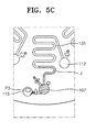
- FIG. 5C is a photographic image illustrating results of a pumping performance test performed on a pump unit including naphthalene powder as a gas generating agent.
- FIGS. 6 and 7 plan views illustrating pump units according to another embodiment of the present invention.
- a pump unit and a centrifugal microfluidic system including the pump unit will now be described more fully with reference to the accompanying drawings, in which exemplary embodiments of the invention are shown.
- FIG. 2 is a view illustrating a pump unit 30 according to an embodiment of the present invention.
- the pump unit 30 includes a gas generating agent 32 disposed close to a fluid (F).
- the fluid (F) is in a channel 31 and may be stationary.
- An energy source 35 supplies energy to the gas generating agent 32.
- the gas generating agent 32 and the fluid (F) can be contained in a fluid treatment substrate 40 such as a lab-on-a-chip.
- the external energy source 35 supplies energy to the gas generating agent 32. In an embodiment, it does not make contact with the substrate 40 or the gas generating agent 32.
- the external energy source 35 may supply energy to the gas generating agent 32 by radiating electromagnetic waves.
- the external energy source 35 may include a laser source, such as a laser diode (LD), emitting a laser beam (L).
- the substrate 40 may be transparent so that a laser beam (L) emitted from the external energy source 35 can be incident onto the gas generating agent 32 with less energy loss.
- LD laser diode
- L laser beam
- the gas generating agent 32 may be a mixture of heating particles and a sublimation material.
- the sublimation material my be present in the form of powder.
- the heating particles generate heat when they absorb energy.
- the sublimation material powder changes directly into gas from solid without an intermediate liquid phase when being heated under atmospheric pressure.
- the sublimation material powder may be formed of a material selected from the group consisting of naphthalene, dry ice, iodine, camphor, and paradichlorobenzene.
- the heating particles have a diameter of several tens to several hundreds of nanometers. When energy is supplied to the heating particles, for example, by laser radiation, the heating particles increase in temperature rapidly and emit heat.
- the heating particles may be ferromagnetic metal oxide particles.
- the heating particles may include Al 2 O 3 , TiO 2 , Ta 2 O 3 , Fe 2 O 3 , Fe 3 O 4 or HfO 2 .
- the sublimation material varies in vapor pressure with respect to temperature.
- the external energy source 35 emits a laser beam (L) onto the gas generating agent 32
- the heating particles (not shown) included in the gas generating agent 32 are rapidly heated by the laser beam (L), and thus the sublimation material changes into gas, increasing its volume and air pressure.
- an increased pressure is applied to fluid (F) to be moved into a direction opposite from the location of the gas generating agent 32.
- a continuous-wave laser beam having a power of 10 mW or larger can heat the gas generating agent 32.
- rapid fluid pumping can be provided by a continuous-wave laser beam having a power of 1.5 W to 2.0 W.
- the pressure between the gas generating agent 32 and the fluid (F) at the stationary position is increased, and the fluid (F) is moved away from the gas generating agent 32 by the increased pressure to the position shown by the solid line.
- the azide may be one selected from the group consisting of an inorganic azide, alkyl azide, and aryl azide, and the inorganic azide may be NaN 3 .
- the azo compound may be one selected from the group consisting of AIBN (Azobisisobutyronitrile), ADVN (2,2'-Azobis-(4-methoxy-2,4-dimethylvaleronitrile)), AMBN (2,2'-Azobis-(2-methylbutyronitrile)), ACHN (1,1'-Azobis-(4-cyclohexanecarbonitrile)), ACCN (1,1'-Azobis-(cyclohexanecarbonitrile)), ABAH (2,2'-Azobis-(2-methylbutyronitrile)), and ACVA (1,1'-Azobis-(cyclohexanecarbonitrile)).
- AIBN Azobisisobutyronitrile
- ADVN 2,2'-Azobis-(4-methoxy-2,4-dimethylvaleronitrile)
- AMBN 2,2'-Azobis-(2-methylbutyronitrile)
- the pump unit 30 may include a heating agent 33 that includes heating particles but does not include sublimation material powder, azide powder, or azo compound powder.
- a heating agent 33 that includes heating particles but does not include sublimation material powder, azide powder, or azo compound powder.
- the heating particles When a laser beam (L) is irradiated onto the heating agent 33, the heating particles generate heat rapidly, and thus air between the heating agent 33 and the fluid (F) at the original position shown by the imaginary line is increased in temperature and pressure. Therefore, the fluid (F) is pushed by the increased pressure to the position shown by the solid line.
- the heating agent 33 including only the heating particles is less effective as compared with the gas generating agent 32 in terms of pumping performance.
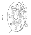
- FIG. 3 is a perspective view illustrating a centrifugal microfluidic system 100 including a pump unit according to an embodiment of the present invention
- FIG. 4 is a sectional view taken along line IV-IV of FIG. 3 , according to an embodiment of the present invention.
- the substrate 102 further includes main channels 105 forming fluid passages, first and second fluid chambers 107 and 112 connected to either end of the main channels 105, accommodation chambers 115 formed adjacent to the first fluid chambers 107, and pump channels 117 connecting the first fluid chambers 107 and the accommodation chambers 115.
- the first fluid chambers 107 in which fluids (F) are contained are positioned farther from a rotation center of the substrate 102 (i.e., the spindle motor 145) than the second fluid chambers 112.
- Reference numeral 108 denotes fluid injection holes for injecting fluids into the first fluid chambers 107
- reference numeral 109 denotes vent holes of the first fluid chambers 107
- reference numeral 113 denotes vent holes of the second fluid chambers 112.
- the centrifugal microfluidic system 100 further includes valve units 125 in the pump channels 117 between the accommodation chambers 115 and the first fluid chambers 107. Each valve unit 125 can close the pump channel 117 to prevent the fluid (F) from moving from the first fluid chamber 107 to the accommodation chamber 115 in which the gas generating agent 120 or the heating agent 121 is filled.
- the valve unit 125 includes a valve filler 130 contained in the pump channel 117.
- the valve filler 130 includes a phase transition material and heating particles for generating heat upon application of energy.
- the phase transition material may be dispersed in the phase transition material.
- the energy may be applied by an external energy source. In an embodiment, a single energy source may be used to supply energy to the gas generating agent 120 (or heating agent 121) and the valve filler 130 at the same time.
- the phase transition material may be wax, gel, or a thermoplastic resin.
- the wax may be paraffin wax.
- the gel may be polyacrylamide, polyacrylates, polymethacrylates, or polyvinylamides.
- the thermoplastic resin may be COC (cyclic olefin copolymer), PMMA (polymethylmethacrylate), PC (polycarbonate), PS (polystyrene), POM (polyoxymethylene), PFA (perfluoralkoxy), PVC (polyvinylchloride), PP (polypropylene), PET (polyethylene terephthalate), PEEK (polyetheretherketone), PA (polyamide), PSU (polysulfone), or PVDF(polyvinylidene fluoride).
- one of the upper and lower plates for example the lower plate 104 may include a sunk area 128 for receiving a molten valve filler 130
- the upper plate 103 may include a valve filler injection hole 126 for injecting a molten valve filler 130 into the pump channel 117.
- the valve filler injection hole 126 is not aligned with the sunk area 128.
- valve filler 130 remaining in the pump channel 117 decreases its viscosity (e.g., solidification), thereby closing the pump channel 117.
- the valve filler injection hole 126 can be sealed with a proper member such as tape 132 to prevent permeation of air.
- a proper member such as tape 132
- the CD shaped substrate 102 is coupled to the spindle motor 145, and the spindle motor 145 is driven to rotate the substrate 102 at a high speed. Then, a fluid injected into the substrate 102 is moved in a radial direction of the substrate 102. That is, a fluid contained in the main channel 105 is moved from the center of the substrate 102 to the periphery.
- a fluid (F) is injected into the first fluid chamber 107, and a gas generating agent 120 or a heating agent 121 is injected into the accommodation chamber 115.
- the fluid injection hole 108, the vent hole 109, and the injection hole 116 are closed with tape (not shown) or the like.
- a laser beam (L) is irradiated on the gas generating agent 120 (or the heating agent 121) and the valve filler 130 filled in the pump channel 117 using the external energy source 140.
- the valve filler 130 melts, and thus the pump channel 117 is opened. Meanwhile, heating particles included in the gas generating agent 120 or the heating agent 121 generate heat rapidly and increase the pressure of the pump channel 117.
- FIGs. 3 and 4 illustrate an exemplary configuration of centrifugal microfluidic system
- the configuration of channels, chambers, holes and other components of the system may be modified depending on the particular uses or needs of the centrifugal microfluidic system. Such modification is within the knowledge and practice of one skilled in the art.
- a pumping performance test was performed to compare the performance of the pump unit in the case of using the gas generating agent 120 with that in the case of the heating agent 121, and the test results are shown in FIGS. 5A through 5C .
- a 1.5-W continuous-wave laser beam (L) was irradiated from the external energy source 140 on the gas generating agent 120, the heating agent 121, and the valve fill 130 for fifteen seconds.
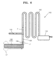
- FIGS. 6 and 7 are plan views illustrating pump units according to another embodiments of the present invention.
- the gas generating agent 160 may be a mixture of heating particles and a sublimation material, azide, or azo compound.
- the sublimation material, azide or azo compound may be used as powder.
- the gas generating agent 160 is the same material as the one explained above with respect to the gas generating agent 32 of the pump unit 30 illustrated in FIG. 2 . Thus, detailed description of the gas generating agent 160 will be omitted.
- the pump unit 150 can include a heating agent 161 formed of only heating particles in replacement of the gas generating agent 160.
- the heating agent 161 is the same as the heating agent 33 of the pump unit 30 of FIG. 2 , and thus description of the heating agent 161 will be omitted.
- a fluid (F) is injected into the main channel 152 through the fluid inlet channel 153, and a laser beam (L1) is irradiated on the valve filler 166 to open the pump channel 163.
- a laser beam (L2) is irradiated on the gas generating agent 160.
- the heating particles included in the gas generating agent 160 generate heat rapidly, and thus the sublimation material rapidly sublimates.
- the pressure of the pump channel 163 increases. Therefore, the fluid (F) filled in a portion of the main channel 152 is moved by the increased pressure away from the gas generating agent 160 toward the fluid chamber 155 through the main channel 152.
- a pump unit 170 of the current embodiment includes a main channel 172 forming a fluid passage, a first fluid chamber 173 connected to an end of the main channel 172, and a second fluid chamber 175 connected to the other end of the main channel 172.
- the pump unit 170 further includes a gas generating agent 180 connected to an end of the first fluid chamber 173 through pump channels 182, 183, and 184, an external energy source (not shown) emitting a laser beam (L2) on the gas generating agent 180, and valves closing and opening the pump channels 182, 183, and 184.
- the first fluid chamber 173 has a triangular shape such that a fluid (F) contained in the first fluid chamber 173 can converge into the main channel 172.
- a side of the first fluid chamber 173 connected to the pump channels 182, 183, and 184 is wider than a side of the first fluid chamber 173 connected to the main channel 172. Since there are three pump channels 182, 183, and 184, a pumping force can be uniformly applied to the fluid (F) through the pump channels 182, 183, and 184. Meanwhile, the valves corresponding to the pump channels 182, 183, and 184 are also three in number.
- the valves include valve fillers 187, 188, and 189 filled in the pump channels 182, 183, and 184, respectively.
- valves and the valve fillers 187, 188, and 189 are the same as those explained above with respect to the valve 125 and the valve fill 130 of the centrifugal microfluidic system 100 illustrated in FIGS. 3 and 4 , and thus descriptions thereof will be omitted.
- a fluid (F) is injected into the first fluid chamber 173, and a laser beam (L1) is irradiated on the valve fillers 187, 188, and 189 to open the pump channels 182, 183, and 184.
- a laser beam (L2) is irradiated on the gas generating agent 180.
- the heating particles included in the gas generating agent 180 generate heat rapidly, and thus the sublimation material powder rapidly sublimates.
- the pressure of the pump channels 182, 183, and 184 increases. Therefore, the fluid (F) filled in the first fluid chamber 173 is moved by the increased pressure away from the gas generating agent 180 toward the second fluid chamber 175 through the main channel 172.
- the pump unit 150 as shown in FIG.
- a laser beam (L2) can be irradiated to the gas generating agent 180 by using a moving energy source from one end to the other end of the gas generating agent 180 as shown by the arrow in FIG. 7 .
- the pump unit does not include a heater, so that a small and integrated fluid treatment device can be provided using the pump unit for applications in the field of microfluidics. Furthermore, the pump unit can be easily applied to a centrifugal microfluidic system having a CD shaped substrate.
- centrifugal microfluidic system including the pump unit, a fluid can be pumped from the periphery to the center of the CD shaped substrate. Therefore, a microfluidic treatment process including a complex biochemical reaction and a detection process for the reaction can be performed in the CD shaped substrate of the centrifugal microfluidic system, and thus the centrifugal microfluidic system can be easily designed for various microfluidic treatment processes.
Abstract
Description
- The present invention relates to micro fluidics, and more particularly, to a pump unit pumping a fluid through a micro channel and a centrifugal microfluidic system including the pump unit.
- Microfluidic systems are used in microfluidic engineering fields for various purposes, such as separating or mixing fluids, performing biochemical reactions, and measuring the results of biochemical reactions. For example, a microfluidic system may include a substrate type device such as a lab-on-a-chip. For microfluidic processing, the substrate type device includes a micro channel forming a fluid passage and a chamber receiving and/or processing a fluid. The microfluidic system may further include a pump unit for generating a fluid stream through the micro channel.
-
FIG. 1 illustrates aconventional pump unit 10 used for pumping a fluid through a micro channel. The pump unit is disclosed inUS Application No. 10/946,818 - Referring to
FIG. 1 , thepump unit 10 includes amain channel 11 formed in asubstrate 1, apropellant chamber 13 formed at anend 11a of themain channel 11, and afluid injection channel 14 formed close to thepropellant chamber 13 and connected to themain channel 11. Apropellant 15 is filled in thepropellant chamber 13. Thepropellant 15 is a mixture of poly tetra fluoro ethylene (PTFE) known as Teflon® and azobis-isobutyronitrile (AIBN). When heated to a temperature of about 70°C or higher, the AIBN generates N2 gas. - The
pump unit 10 further includes aheater 20 to heat thepropellant 15. Theheater 20 generates heat using electricity and is formed in thesubstrate 1 or outside thesubstrate 1 to be in contact with thesubstrate 1. A fluid (F) is injected into themain channel 11 through thefluid injection channel 14, and heat is generated from theheater 20 using electricity to heat thepropellant 15 and generate N2 gas from thepropellant 15. Then, the fluid (F) is moved from theend 11a of themain channel 11 toward theother end 11b by a pressure applied to the fluid (F) by the N2 gas. The movement of the fluid (F) is illustrated by an imaginary dash-point line, a solid line, and arrows therebetween. However, it is difficult to reduce the size of thesubstrate 1 and integrate thesubstrate 1 since theheater 20 should be formed inside or in contact with thesubstrate 1. - Meanwhile, in the field of microfluidics, a centrifugal microfluidic system is well known, which includes a compact disk shaped substrate (CD substrate). A fluid can be pumped outward using a centrifugal force by rotating the CD substrate. The centrifugal microfluidic system can have a highly integrated structure. However, in the centrifugal microfluidic system, a fluid can be pumped only in one way from the center to the periphery. Furthermore, it is difficult to apply the
pump unit 10 illustrated inFIG. 1 to the centrifugal microfluidic system for pumping a fluid from the periphery to the center of the centrifugal microfluidic system since thepump unit 10 includes theheater 20 requiring electricity. Therefore, it is difficult to design a centrifugal microfluidic system that can be used for performing a microfluidic treatment process including a complex biochemical reaction and a detection process for the reaction using a single CD substrate. - The present invention provides a pump unit applying a pumping force to a fluid by supplying energy to a gas generating agent in a non-contact manner, and a centrifugal microfluidic system including the pump unit.
- According to an aspect of the present invention, there is provided a pump unit including a chamber connected to and fluid communicated to the first channel, the chamber being disposed at a upstream side of the fluid which is to be moved toward a downstream side; and a gas generating agent contained in the chamber, wherein the gas generating agent includes a plurality of heating particles or a mixture of the plurality of heating particles and one of a sublimation material, azide, and azo compound; and wherein the gas generating agent increases air pressure when an energy is applied thereto, thereby moving the fluid toward the downstream direction. The pump unit may further include an external energy source. The chamber is connected to the first channel through a second channel.
- According to another aspect of the present invention, there is provided a centrifugal microfluidic system including: a substrate including a channel constituting a fluid passage; and a pump unit moving a fluid in the first channel, wherein the pump unit includes a chamber connected to and fluid communicated to the first channel, the chamber being disposed at a upstream side of the fluid which is to be moved toward a downstream side; and a gas generating agent contained in the chamber, wherein the gas generating agent includes a plurality of heating particles or a mixture of the plurality of heating particles and one of a sublimation material, azide, and azo compound; and wherein the gas generating agent increases air pressure when an energy is applied thereto, thereby moving the fluid toward the downstream direction. The system may further include a driving unit rotating the substrate. The system may further include an external energy source. The chamber is connected to the first channel through a second channel.
- The gas generating material may be a mixture of the plurality of the heating particles and a sublimation material. The sublimation material may be one selected from the group consisting of naphthalene, dry ice, iodine, camphor, and paradichlorobenzene. The sublimation material may be present in the form of powder.
- The azide may be one selected from the group consisting of an inorganic azide, alkyl azide, and aryl azide. The azide may be present in the form of powder.
- The inorganic azide may be NaN3.
- The azo compound may be one selected from the group consisting of AIBN (Azobisisobutyronitrile), DVN (2,2'-Azobis-(4-methoxy-2,4-dunethylvaleronitrile)), AMBN (2,2'-Azobis-(2-methylbutyronitrile)), CHN (1,1'-Azobis-(4-cyclohexanecarbonitrile)), ACCN (1,1'-Azobis-(cyclohexanecarbonitrile)), ABAH (2,2'-Azobis-(2-methylbutyronitrile)), and ACVA (1,1'-Azobis-(cyclohexanecarbonitrile)). The azo compound may be present in the form of powder.
- The external energy source may emit electromagnetic waves towards the gas generating agent.
- The electromagnetic waves may be in the form of a laser beam, and the external energy source may include a laser source generating a laser beam.
- The laser source may generate a continuous-wave laser beam having an output power of at least 10 mW.
- The external energy source may emit electromagnetic waves towards the gas generating agent while scanning from an end of the gas generating agent to the other end of the gas generating agent.
- The pump unit further may include a valve closing the second valve. The valve may be located in the second channel (pump channel) between the fluid and the gas generating agent so as to prevent the fluid from flowing to the gas generating agent, wherein the valve opens the pump channel when the gas generating agent increases air pressure in the pump channel by an application of energy, thereby moving the fluid toward the downstream direction.
- The valve may include a valve filler filled in at least part of the pump channel, the valve filler including a phase transition material, wherein when energy is supplied to the valve filler, a viscosity of the valve filler reduces, thereby opening the pump channel..
- The phase transition material may be one selected from the group consisting of wax, gel, and a thermoplastic resin.
- The valve filler may further include a plurality of heating particles dispersed into the phase transition material, the heating particles generating heat by absorbing energy.
- The heating particles may be ferromagnetic particles.
- The heating particles may be metal oxide particles.
- The metal oxide particles may be Al2O3, TiO2, Ta2O3, Fe2O3, Fe3O4, or HfO2.
- The gas generating agent and the valve may be supplied with energy by a single external energy source.
- The above and other features and advantages of the present invention will become more apparent by describing in detail exemplary embodiments thereof with reference to the attached drawings in which:
-
FIG. 1 is a plan view illustrating a conventional pump unit; -
FIG. 2 is a view illustrating a pump unit according to an embodiment of the present invention; -
FIG. 3 is a perspective view illustrating a centrifugal microfluidic system including a pump unit according to an embodiment of the present invention; -
FIG. 4 is a sectional view taken along line IV-IV ofFIG. 3 , according to an embodiment of the present invention; -
FIG. 5A is a photographic image illustrating results of a pumping performance test performed on a pump unit including a mixture of iron oxide powder and naphthalene powder as a gas generating agent; -
FIG. 5B is a photographic image illustrating results of a pumping performance test performed on a pump unit including iron oxide powder as a heating agent; -
FIG. 5C is a photographic image illustrating results of a pumping performance test performed on a pump unit including naphthalene powder as a gas generating agent; and -
FIGS. 6 and7 plan views illustrating pump units according to another embodiment of the present invention. - A pump unit and a centrifugal microfluidic system including the pump unit will now be described more fully with reference to the accompanying drawings, in which exemplary embodiments of the invention are shown.
-
FIG. 2 is a view illustrating apump unit 30 according to an embodiment of the present invention. - Referring to
FIG. 2 , thepump unit 30 includes agas generating agent 32 disposed close to a fluid (F). The fluid (F) is in achannel 31 and may be stationary. Anenergy source 35 supplies energy to thegas generating agent 32. Thegas generating agent 32 and the fluid (F) can be contained in afluid treatment substrate 40 such as a lab-on-a-chip. Theexternal energy source 35 supplies energy to thegas generating agent 32. In an embodiment, it does not make contact with thesubstrate 40 or thegas generating agent 32. Theexternal energy source 35 may supply energy to thegas generating agent 32 by radiating electromagnetic waves. For example, theexternal energy source 35 may include a laser source, such as a laser diode (LD), emitting a laser beam (L). Thesubstrate 40 may be transparent so that a laser beam (L) emitted from theexternal energy source 35 can be incident onto thegas generating agent 32 with less energy loss. - The
gas generating agent 32 may be a mixture of heating particles and a sublimation material. The sublimation material my be present in the form of powder. The heating particles generate heat when they absorb energy. The sublimation material powder changes directly into gas from solid without an intermediate liquid phase when being heated under atmospheric pressure. The sublimation material powder may be formed of a material selected from the group consisting of naphthalene, dry ice, iodine, camphor, and paradichlorobenzene. - The heating particles have a diameter of several tens to several hundreds of nanometers. When energy is supplied to the heating particles, for example, by laser radiation, the heating particles increase in temperature rapidly and emit heat. The heating particles may be ferromagnetic metal oxide particles. For example, the heating particles may include Al2O3, TiO2, Ta2O3, Fe2O3, Fe3O4 or HfO2.
- The sublimation material varies in vapor pressure with respect to temperature. When the
external energy source 35 emits a laser beam (L) onto thegas generating agent 32, the heating particles (not shown) included in thegas generating agent 32 are rapidly heated by the laser beam (L), and thus the sublimation material changes into gas, increasing its volume and air pressure. As a result, an increased pressure is applied to fluid (F) to be moved into a direction opposite from the location of thegas generating agent 32. For example, when the fluid (F) is positioned at is stationary or starting point shown by an imaginary line, the pressure between thegas generating agent 32 and the fluid (F) at the stationary position is increased, and the fluid (F) is moved away from thegas generating agent 32 by the increased pressure to another position shown by a solid line. A continuous-wave laser beam having a power of 10 mW or larger can heat thegas generating agent 32. For example, rapid fluid pumping can be provided by a continuous-wave laser beam having a power of 1.5 W to 2.0 W. - The
gas generating agent 32 of thepump unit 30 may be a mixture of heating particles and azide or azo compound powder. The azide or azo compound powder decomposes and generates N2 gas when being heated. When theexternal energy source 35 irradiates a laser beam (L) onto thegas generating agent 32, the heating particles included in thegas generating agent 32 are rapidly heated by the laser beam (L), and thus the azide or azo compound powder composes to generate N2 gas, increasing its volume. As a result, an increased pressure is applied to fluid (F) to be moved into a direction opposite from the location of thegas generating agent 32. For example, when the fluid (F) is positioned at is stationary or starting point shown by an imaginary line, the pressure between thegas generating agent 32 and the fluid (F) at the stationary position is increased, and the fluid (F) is moved away from thegas generating agent 32 by the increased pressure to the position shown by the solid line. - The azide may be one selected from the group consisting of an inorganic azide, alkyl azide, and aryl azide, and the inorganic azide may be NaN3.
- The azo compound may be one selected from the group consisting of AIBN (Azobisisobutyronitrile), ADVN (2,2'-Azobis-(4-methoxy-2,4-dimethylvaleronitrile)), AMBN (2,2'-Azobis-(2-methylbutyronitrile)), ACHN (1,1'-Azobis-(4-cyclohexanecarbonitrile)), ACCN (1,1'-Azobis-(cyclohexanecarbonitrile)), ABAH (2,2'-Azobis-(2-methylbutyronitrile)), and ACVA (1,1'-Azobis-(cyclohexanecarbonitrile)).
- The
pump unit 30 may include a heating agent 33 that includes heating particles but does not include sublimation material powder, azide powder, or azo compound powder. When a laser beam (L) is irradiated onto the heating agent 33, the heating particles generate heat rapidly, and thus air between the heating agent 33 and the fluid (F) at the original position shown by the imaginary line is increased in temperature and pressure. Therefore, the fluid (F) is pushed by the increased pressure to the position shown by the solid line. The heating agent 33 including only the heating particles is less effective as compared with thegas generating agent 32 in terms of pumping performance. -
FIG. 3 is a perspective view illustrating a centrifugalmicrofluidic system 100 including a pump unit according to an embodiment of the present invention, andFIG. 4 is a sectional view taken along line IV-IV ofFIG. 3 , according to an embodiment of the present invention. - Referring to
FIGS. 3 and4 , the centrifugalmicrofluidic system 100 includes a compact disk (CD) shapedsubstrate 102, aspindle motor 145 rotating thesubstrate 102, and anexternal energy source 140 emitting a laser beam (L) onto thesubstrate 102. Thesubstrate 102 includes upper andlower plates lower plates upper plate 103 is transparent to reduce energy loss of a laser beam (L). - The
substrate 102 further includesmain channels 105 forming fluid passages, first and secondfluid chambers main channels 105,accommodation chambers 115 formed adjacent to the firstfluid chambers 107, and pumpchannels 117 connecting the firstfluid chambers 107 and theaccommodation chambers 115. The firstfluid chambers 107 in which fluids (F) are contained are positioned farther from a rotation center of the substrate 102 (i.e., the spindle motor 145) than the secondfluid chambers 112.Reference numeral 108 denotes fluid injection holes for injecting fluids into the firstfluid chambers 107,reference numeral 109 denotes vent holes of the firstfluid chambers 107, andreference numeral 113 denotes vent holes of the secondfluid chambers 112. - A
gas generating agent 120 orheating agent 121 are filled in theaccommodation chamber 115. As explained with reference toFIG. 2 , thegas generating agent 120 may be a mixture including heating particles and sublimation material powder, or thegas generating agent 120 may be a mixture including heating particles and azide or azo compound powder. Theheating agent 121 includes heating particles but does not include sublimation material powder, azide powder, or azo compound powder.Reference numeral 116 denotes an injection hole for injecting thegas generating agent 120 or theheating agent 121 into theaccommodation chamber 115. - The centrifugal
microfluidic system 100 further includesvalve units 125 in thepump channels 117 between theaccommodation chambers 115 and the firstfluid chambers 107. Eachvalve unit 125 can close thepump channel 117 to prevent the fluid (F) from moving from the firstfluid chamber 107 to theaccommodation chamber 115 in which thegas generating agent 120 or theheating agent 121 is filled. Thevalve unit 125 includes avalve filler 130 contained in thepump channel 117. Thevalve filler 130 includes a phase transition material and heating particles for generating heat upon application of energy. The phase transition material may be dispersed in the phase transition material. The energy may be applied by an external energy source. In an embodiment, a single energy source may be used to supply energy to the gas generating agent 120 (or heating agent 121) and thevalve filler 130 at the same time. - The phase transition material may be wax, gel, or a thermoplastic resin. For example, the wax may be paraffin wax. The gel may be polyacrylamide, polyacrylates, polymethacrylates, or polyvinylamides. The thermoplastic resin may be COC (cyclic olefin copolymer), PMMA (polymethylmethacrylate), PC (polycarbonate), PS (polystyrene), POM (polyoxymethylene), PFA (perfluoralkoxy), PVC (polyvinylchloride), PP (polypropylene), PET (polyethylene terephthalate), PEEK (polyetheretherketone), PA (polyamide), PSU (polysulfone), or PVDF(polyvinylidene fluoride).
- The heating particles included in the
valve filler 130 may be the same material as those explained with respect to thegas generating agent 120. Thus, description of the heating particles of thevalve filler 130 will be omitted. The heating particles of thevalve filler 130 can be dispersed in a hydrophobic carrier oil. Thevalve filler 130 can be formed by mixing a molten phase transition material with a hydrophobic carrier oil containing heating particles dispersed therein. - In one embodiment, one of the upper and lower plates, for example the
lower plate 104 may include a sunkarea 128 for receiving amolten valve filler 130, and theupper plate 103 may include a valvefiller injection hole 126 for injecting amolten valve filler 130 into thepump channel 117. The valvefiller injection hole 126 is not aligned with the sunkarea 128. When amolten valve filler 130 is injected into thepump channel 117 through the valvefiller injection hole 126, some of themolten valve filler 130 flows into the sunkarea 128 and the rest of themolten valve filler 130 may remain in thepump channel 117 between the valvefiller injection hole 126 and the sunkarea 128. Then, thevalve filler 130 remaining in thepump channel 117 decreases its viscosity (e.g., solidification), thereby closing thepump channel 117. After avalve filler 130 is injected through the valvefiller injection hole 126, the valvefiller injection hole 126 can be sealed with a proper member such astape 132 to prevent permeation of air. Other modifications and changes may be made to thevalve unit 125. Such modifications and changes are described in a co-pending application Serial No. , disclosures of which are incorporated by reference. - The CD shaped
substrate 102 is coupled to thespindle motor 145, and thespindle motor 145 is driven to rotate thesubstrate 102 at a high speed. Then, a fluid injected into thesubstrate 102 is moved in a radial direction of thesubstrate 102. That is, a fluid contained in themain channel 105 is moved from the center of thesubstrate 102 to the periphery. - A fluid (F) is injected into the first
fluid chamber 107, and agas generating agent 120 or aheating agent 121 is injected into theaccommodation chamber 115. Next, thefluid injection hole 108, thevent hole 109, and theinjection hole 116 are closed with tape (not shown) or the like. Thereafter, a laser beam (L) is irradiated on the gas generating agent 120 (or the heating agent 121) and thevalve filler 130 filled in thepump channel 117 using theexternal energy source 140. Then, thevalve filler 130 melts, and thus thepump channel 117 is opened. Meanwhile, heating particles included in thegas generating agent 120 or theheating agent 121 generate heat rapidly and increase the pressure of thepump channel 117. As a result of the increased pressure, the fluid (F) contained in the firstfluid chamber 107 is moved away from thegas generating agent 120 or theheating agent 121 toward the center of thesubstrate 102 through themain channel 105. The fluid moves into thesecond chamber 112, where the fluid may be processed or reacted appropriately. - Even though
Figs. 3 and4 illustrate an exemplary configuration of centrifugal microfluidic system, it should be noted that the configuration of channels, chambers, holes and other components of the system may be modified depending on the particular uses or needs of the centrifugal microfluidic system. Such modification is within the knowledge and practice of one skilled in the art. - A pumping performance test was performed to compare the performance of the pump unit in the case of using the
gas generating agent 120 with that in the case of theheating agent 121, and the test results are shown inFIGS. 5A through 5C . In the pumping performance test, a 1.5-W continuous-wave laser beam (L) was irradiated from theexternal energy source 140 on thegas generating agent 120, theheating agent 121, and the valve fill 130 for fifteen seconds. - In the case of
FIG. 5A , a gas generating agent P1 was used. The gas generating agent P1 was a mixture including iron oxide powder as heating particles and naphthalene powder as sublimation material powder. Most of a fluid (F) contained in the firstfluid chamber 107 was pumped to the secondfluid chamber 112 through themain channel 105. That is, it can be understood that the gas generating agent P1 formed of heating particles and sublimation material powder provides good fluid pumping performance. - In the case of
FIG. 5B , a heating agent P2 formed of only iron oxide powder was used. A fluid (F) contained in the firstfluid chamber 107 was pumped to a middle part of themain channel 105. It can be understood that the heating agent P2 provides good fluid pumping performance to some degree although the heating agent P2 provides relatively lower pumping performance than the gas generating agent P1 (refer toFIG. 5A ). - In the case of
FIG. 5C , a gas generating agent P3 formed of only naphthalene powder is used. A fluid (F) contained in the firstfluid chamber 107 was not well pumped. The reason for this is that it is difficult to heat a sublimation material such as naphthalene to a sufficiently high temperature for sublimation by supplying energy to the sublimation material by a non-contact type method such as using a laser beam (L). Therefore, the gas generating agent P3 formed of only a sublimation material without heating particles is not used in the pump unit 30 (refer toFIG. 2 ) or the centrifugal microfluidic system 100 (refer toFIG. 3 ) of the present invention. -
FIGS. 6 and7 are plan views illustrating pump units according to another embodiments of the present invention. - Referring to
FIG. 6 , apump unit 150 of the current embodiment includes amain channel 152 forming a fluid passage, afluid inlet channel 153 connected to an end of themain channel 152, agas generating agent 160 connected to the end of themain channel 152 through apump channel 163, and afluid chamber 155 connected to the other end of themain channel 152. Thepump unit 150 further includes an external energy source (not shown) emitting a laser beam (L2) on thegas generating agent 160, and a valve closing and opening thepump channel 163. - The
gas generating agent 160 may be a mixture of heating particles and a sublimation material, azide, or azo compound. The sublimation material, azide or azo compound may be used as powder. Thegas generating agent 160 is the same material as the one explained above with respect to thegas generating agent 32 of thepump unit 30 illustrated inFIG. 2 . Thus, detailed description of thegas generating agent 160 will be omitted. Alternatively, thepump unit 150 can include aheating agent 161 formed of only heating particles in replacement of thegas generating agent 160. Theheating agent 161 is the same as the heating agent 33 of thepump unit 30 ofFIG. 2 , and thus description of theheating agent 161 will be omitted. - The value includes a
valve filler 166 filled in thepump channel 163. Thevalve filler 166 and the valve are the same as those explained above with respect to thevalve filler 130 and thevalve 125 of the centrifugalmicrofluidic system 100 illustrated inFIGS. 3 and4 . Thus, detailed descriptions of thevalve filler 166 and the valve including thevalve filler 166 will be omitted. A laser beam (L1) can be irradiated on thevalve filler 166 using the same external energy source (not shown) used to irradiate a laser beam (L2) on thegas generating agent 160, or using an additional external energy source. - A fluid (F) is injected into the
main channel 152 through thefluid inlet channel 153, and a laser beam (L1) is irradiated on thevalve filler 166 to open thepump channel 163. Next, a laser beam (L2) is irradiated on thegas generating agent 160. Then, the heating particles included in thegas generating agent 160 generate heat rapidly, and thus the sublimation material rapidly sublimates. As a result, the pressure of thepump channel 163 increases. Therefore, the fluid (F) filled in a portion of themain channel 152 is moved by the increased pressure away from thegas generating agent 160 toward thefluid chamber 155 through themain channel 152. - The fluid pumping performance of the
pump unit 150 can be improved by increasing the amount of thegas generating agent 160. However, in this case, the external energy source should include more laser diodes (LDs) to simultaneously irradiate thegas generating agent 160 disposed in a relatively large area, and the external energy source will consume more power. Thus, the cost for operation will increase. This cost increase can be avoided by using an external energy source which can move along, while it irradiates onto thegas generating agent 160, from one end to the other end of thegas generating agent 160 which occupies a relatively large area, as shown by the arrow next to thegas generating agent 160 inFIG. 6 . In this way, the fluid pumping performance of thepump unit 150 can be improved at low cost by increasing the amount of thegas generating agent 160 without increasing the number of LDs of theexternal energy source 35. - Referring to
FIG. 7 , apump unit 170 of the current embodiment includes amain channel 172 forming a fluid passage, a firstfluid chamber 173 connected to an end of themain channel 172, and a secondfluid chamber 175 connected to the other end of themain channel 172. Thepump unit 170 further includes agas generating agent 180 connected to an end of the firstfluid chamber 173 throughpump channels gas generating agent 180, and valves closing and opening thepump channels - The first
fluid chamber 173 has a triangular shape such that a fluid (F) contained in the firstfluid chamber 173 can converge into themain channel 172. A side of the firstfluid chamber 173 connected to thepump channels fluid chamber 173 connected to themain channel 172. Since there are threepump channels pump channels pump channels valve fillers pump channels valve fillers valve 125 and the valve fill 130 of the centrifugalmicrofluidic system 100 illustrated inFIGS. 3 and4 , and thus descriptions thereof will be omitted. - The
gas generating agent 180 may be a mixture of heating particles and a sublimation material, azide, or azo compound. The sublimation material, azide or azo compound may be used in the form of powder. Thegas generating agent 180 is the same as thegas generating agent 32 of thepump unit 30 illustrated inFIG. 2 . Thus, detailed description of thegas generating agent 180 will be omitted. Alternatively, thepump unit 170 can include aheating agent 181 formed of only heating particles in replacement of thegas generating agent 180. Theheating agent 181 is the same as the heating agent 33 of thepump unit 30 ofFIG. 2 , and thus description of theheating agent 181 will be omitted. - A laser beam (L1) can be irradiated on the
valve fillers gas generating agent 180, or using an additional external energy source. - A fluid (F) is injected into the first
fluid chamber 173, and a laser beam (L1) is irradiated on thevalve fillers pump channels gas generating agent 180. Then, the heating particles included in thegas generating agent 180 generate heat rapidly, and thus the sublimation material powder rapidly sublimates. As a result, the pressure of thepump channels fluid chamber 173 is moved by the increased pressure away from thegas generating agent 180 toward the secondfluid chamber 175 through themain channel 172. Like in the case of thepump unit 150 as shown inFIG. 6 , when thegas generating agent 180 is filled in a large area, a laser beam (L2) can be irradiated to thegas generating agent 180 by using a moving energy source from one end to the other end of thegas generating agent 180 as shown by the arrow inFIG. 7 . - As described above, according to the present invention, the pump unit does not include a heater, so that a small and integrated fluid treatment device can be provided using the pump unit for applications in the field of microfluidics. Furthermore, the pump unit can be easily applied to a centrifugal microfluidic system having a CD shaped substrate.
- In the centrifugal microfluidic system including the pump unit, a fluid can be pumped from the periphery to the center of the CD shaped substrate. Therefore, a microfluidic treatment process including a complex biochemical reaction and a detection process for the reaction can be performed in the CD shaped substrate of the centrifugal microfluidic system, and thus the centrifugal microfluidic system can be easily designed for various microfluidic treatment processes.
- While the present invention has been particularly shown and described with reference to exemplary embodiments thereof, it will be understood by those of ordinary skill in the art that various changes in form and details may be made therein without departing from the spirit and scope of the present invention as defined by the following claims.
Claims (25)
- A pump unit to move a fluid in a first channel, comprising:a chamber connected to and fluid communicated to the first channel, the chamber being disposed at a upstream side of the fluid which is to be moved toward a downstream side; anda gas generating agent contained in the chamber,wherein the gas generating agent includes a plurality of heating particles; and
wherein the gas generating agent increases air pressure when an energy is applied thereto, thereby moving the fluid toward the downstream direction. - The pump unit of claim 1, wherein the gas generating agent further comprises one selected from the group consisting of a sublimation material, azide, and azo compound.
- The pump unit of claim 2, wherein the sublimation material is one selected from the group consisting of naphthalene, dry ice, iodine, camphor, and paradichlorobenzene.
- The pump unit of claim 2, wherein the azide is one selected from the group consisting of an inorganic azide, alkyl azide, and aryl azide.
- The pump unit of claim 2, wherein the azo compound is one selected from the group consisting of AIBN (Azobisisobutyronitrile), ADVN (2,2'-Azobis-(4-methoxy-2,4-dimethylvaleronitrile)), AMBN (2,2'-Azobis-(2-methylbutyronitrile)), ACHN (1,1'-Azobis-(4-cyclohexane-carbonitrile)), ACCN (1,1'-Azobis-(cyclohexanecarbonitrile)), ABAH (2,2'-Azobis-(2-methylbutyronitrile)), and ACVA (1,1'-Azobis-(cyclo-hexanecarbonitrile)).
- The pump unit of claim 1, further comprising a valve, which is located in the second channel and closes the second channel, wherein the valve opens the second channel when the gas generating agent increases air pressure in the second channel by an application of energy, thereby moving the fluid toward a downstream direction.
- The pump unit of claim 6, wherein the valve comprises a valve filler filled in at least pant of the second channel, the valve filler including a phase transition material selected from the group consisting of wax, gel, and a thermoplastic resin,
wherein when external energy is supplied to the valve filler, a viscosity of the valve filler reduces, thereby opening the second channel. - The pump unit of claim 7, wherein the valve filler further includes a plurality of heating particles dispersed into the phase transition material, the heating particles generating heat by absorbing energy.
- The pump unit of claim 1, wherein the heating particles are a ferromagnetic material particle or a metal oxide particle.
- The pump unit of claim 8, wherein the heating particles are a ferromagnetic material particle or a metal oxide particle.
- The pump unit of claim 2, wherein the sublimation material, azide, and azo compound are present in the form of powder.
- A centrifugal microfluidic system comprising:a substrate including a first channel constituting a fluid passage; anda pump unit moving a fluid in the first channel,
wherein the pump unit comprises:a chamber formed in the substrate and connected to the first channel, the chamber being disposed at a upstream side of the fluid which is to be moved toward a downstream side; anda gas generating agent contained in the chamber,
wherein the gas generating agent includes a plurality of heating particles; and
wherein the gas generating agent increases air pressure when an energy is applied thereto, thereby moving the fluid toward the downstream direction. - The centrifugal microfluidic system of claim 12, further comprising a driving unit rotating the substrate.
- The centrifugal microfluidic system of claim 12, which further comprises an external energy source which emits electromagnetic waves towards the gas generating agent.
- The centrifugal microfluidic system of claim 12, wherein the gas generating agent further comprises one selected from the group consisting of a sublimation material, azide, and azo compound.
- The centrifugal microfluidic system of claim 15, wherein the sublimation material is one selected from the group consisting of naphthalene, dry ice, iodine, camphor, and paradichlorobenzene.
- The centrifugal microfluidic system of claim 15, wherein the azide is one selected from the group consisting of an inorganic azide, alkyl azide, and aryl azide.
- The centrifugal microfluidic system of claim 15, wherein the azo compound is one selected from the group consisting of AIBN (Azobisisobutyronitrile), ADVN (2,2'-Azobis-(4-methoxy-2,4-dimethylvaleronitrile)), AMBN (2,2'-Azobis-(2-methylbutyronitrile)), ACHN (1,1'-Azobis-(4-cyclohexanecarbonitrile)), ACCN (1,1'-Azobis-(cyclohexanecarbonitrile)), ABAH (2,2'-Azobis-(2-methylbutyronitrile)), and ACVA (1,1'-Azobis-(cyclohexanecarbonitrile)).
- The centrifugal microfluidic system of claim 14, wherein the external energy source emits electromagnetic waves towards the gas generating agent while scanning from an end of the gas generating agent to the other end of the gas generating agent.
- The centrifugal microfluidic system of claim 12, wherein the chamber of the pump unit is connected to the first channel of the pump unit through a second channel, the pump unit further comprising a valve, which is located in the second channel and closes the second channel; and
wherein the valve opens the second channel when the gas generating agent increases air pressure in the second channel by an application of energy, thereby moving the fluid toward the downstream direction. - The centrifugal microfluidic system of claim 20, wherein the valve comprises a valve filler filled in at least part of the second channel, the valve filler including a phase transition material selected from the group consisting of wax, gel and a thermoplastic resin,
wherein when external energy is supplied to the valve filler, a viscosity of the valve filler reduces, thereby opening the second channel. - The centrifugal microfluidic system of claim 21, wherein the valve filler further includes a plurality of heating particles dispersed into the phase transition material, the heating particles generating heat by absorbing energy.
- The centrifugal microfluidic system of claim 12, wherein the heating particles are a ferromagnetic material particle or a metal oxide particle.
- The centrifugal microfluidic system of claim 22, wherein the heating particles are a ferromagnetic material particle or a metal oxide particle.
- The centrifugal microfluidic system of claim 15, wherein the sublimation material, azide, and azo compound are present in the form of powder.
Applications Claiming Priority (1)
| Application Number | Priority Date | Filing Date | Title |
|---|---|---|---|
| KR1020070025148A KR20080084049A (en) | 2007-03-14 | 2007-03-14 | Pump unit and centrifugal force based microfluidic system with the same |
Publications (1)
| Publication Number | Publication Date |
|---|---|
| EP1970565A1 true EP1970565A1 (en) | 2008-09-17 |
Family
ID=39522356
Family Applications (1)
| Application Number | Title | Priority Date | Filing Date |
|---|---|---|---|
| EP07118466A Withdrawn EP1970565A1 (en) | 2007-03-14 | 2007-10-15 | Pump unit and centrifugal microfluidic system having the same |
Country Status (4)
| Country | Link |
|---|---|
| US (1) | US20080226504A1 (en) |
| EP (1) | EP1970565A1 (en) |
| JP (1) | JP2008224662A (en) |
| KR (1) | KR20080084049A (en) |
Cited By (9)
| Publication number | Priority date | Publication date | Assignee | Title |
|---|---|---|---|---|
| WO2009079051A2 (en) * | 2007-09-19 | 2009-06-25 | Nanogen, Inc. | Counter-centrifugal force device |
| DE102009001612A1 (en) * | 2009-03-17 | 2010-09-30 | Si Analytics Gmbh | Apparatus for generating constant pulsation free fluid flow for micro-fluidic applications, comprises reservoir, which is impinged with compressed gas with constant gas pressure |
| EP2332653A1 (en) * | 2009-12-14 | 2011-06-15 | F. Hoffmann-La Roche AG | Systems and method for manipulating liquid fluids in microfluidic devices |
| CN103807502A (en) * | 2013-12-16 | 2014-05-21 | 浙江大学 | Thermal control variable flow resistance device |
| WO2015051950A1 (en) * | 2013-10-08 | 2015-04-16 | Hahn-Schickard-Gesellschaft für angewandte Forschung e.V. | Device and method for stirring at least one liquid |
| WO2015051993A1 (en) * | 2013-10-08 | 2015-04-16 | Robert Bosch Gmbh | Method for mixing liquids and microfluidic centrifugal system |
| EP3114454A4 (en) * | 2014-03-07 | 2017-12-06 | National Research Council of Canada | Centrifugal microfluidic chip control |
| WO2018183622A1 (en) * | 2017-03-30 | 2018-10-04 | 908 Devices Inc. | Microfluidic analysis of biological samples |
| WO2018215777A1 (en) * | 2017-05-24 | 2018-11-29 | Heriot-Watt University | Microfluidic mixing |
Families Citing this family (11)
| Publication number | Priority date | Publication date | Assignee | Title |
|---|---|---|---|---|
| JP5403593B2 (en) * | 2009-03-27 | 2014-01-29 | 国立大学法人 筑波大学 | Automatic solution injection device |
| KR101120136B1 (en) | 2010-03-10 | 2012-03-22 | 주식회사 넥스비보 | Micro-particle processing device using centrifugal force |
| KR101145806B1 (en) * | 2010-05-07 | 2012-05-16 | 한국과학기술원 | containment vessel cooling system using the gas generation reaction |
| KR101116809B1 (en) * | 2010-05-25 | 2012-02-28 | 연세대학교 산학협력단 | Method for focusing micro particles |
| KR101347747B1 (en) * | 2011-05-13 | 2014-01-06 | 성균관대학교산학협력단 | Radioactive compound synthesizing apparatus having hot melt valve |
| JP5798816B2 (en) * | 2011-06-30 | 2015-10-21 | 積水化学工業株式会社 | Micropump and microfluidic device |
| TWI456196B (en) | 2012-04-24 | 2014-10-11 | Ind Tech Res Inst | Immunoassay test apparatus |
| CN103008038B (en) * | 2013-01-11 | 2015-07-01 | 西安交通大学 | Bipolar electrode-paper-based microfluidics type chip and preparation method thereof |
| KR20150027939A (en) | 2013-09-04 | 2015-03-13 | 삼성전자주식회사 | Microfluidic apparatus |
| KR102176587B1 (en) | 2013-10-15 | 2020-11-10 | 삼성전자주식회사 | Sample analysis method, and dynamic valve operating method |
| CN107400920B (en) * | 2016-05-19 | 2019-10-29 | 中国科学院微电子研究所 | It is a kind of for growing the preprocess method of single crystal orientation zinc oxide |
Citations (4)
| Publication number | Priority date | Publication date | Assignee | Title |
|---|---|---|---|---|
| EP1442787A2 (en) * | 2002-12-18 | 2004-08-04 | Matsushita Electric Industrial Co., Ltd. | Micropump |
| US20050130292A1 (en) * | 2003-09-26 | 2005-06-16 | The University Of Cincinnati | Smart disposable plastic lab-on-a-chip for point-of-care testing |
| US20050232817A1 (en) * | 2003-09-26 | 2005-10-20 | The University Of Cincinnati | Functional on-chip pressure generator using solid chemical propellant |
| EP1844936A1 (en) * | 2006-04-13 | 2007-10-17 | Technische Universität Chemnitz | Microactor, method for displacing a fluid and method for manufacturing a microactor |
Family Cites Families (12)
| Publication number | Priority date | Publication date | Assignee | Title |
|---|---|---|---|---|
| GB9804483D0 (en) * | 1998-03-02 | 1998-04-29 | Central Research Lab Ltd | Apparatus for and method of controlling the rate of flow of fluid along a pathway |
| US7348182B2 (en) * | 2000-10-03 | 2008-03-25 | Mirari Biosciences, Inc. | Directed microwave chemistry |
| US6756018B2 (en) * | 2001-02-12 | 2004-06-29 | Agilent Technologies, Inc. | Method and apparatus for selective execution of microfluidic circuits utilizing electrically addressable gas generators |
| US7829025B2 (en) * | 2001-03-28 | 2010-11-09 | Venture Lending & Leasing Iv, Inc. | Systems and methods for thermal actuation of microfluidic devices |
| US20050009101A1 (en) * | 2001-05-17 | 2005-01-13 | Motorola, Inc. | Microfluidic devices comprising biochannels |
| US20030156991A1 (en) * | 2001-10-23 | 2003-08-21 | William Marsh Rice University | Optomechanically-responsive materials for use as light-activated actuators and valves |
| US6814852B2 (en) * | 2002-07-15 | 2004-11-09 | Hewlett-Packard Development Company, L.P. | Generation of gas in a lab-on-a-chip environment |
| JP4352694B2 (en) * | 2002-12-18 | 2009-10-28 | パナソニック株式会社 | Micropump, micropump unit, and sample processing chip |
| JP2004349000A (en) * | 2003-05-20 | 2004-12-09 | Matsushita Electric Ind Co Ltd | Electron gun and cathode-ray tube device |
| KR100668335B1 (en) * | 2005-04-02 | 2007-01-12 | 삼성전자주식회사 | Microvalve having ferromagnetic wax plug and flux control method using ferromagnetic wax |
| US7959876B2 (en) * | 2006-07-17 | 2011-06-14 | Industrial Technology Research Institute | Fluidic device |
| WO2008030541A1 (en) * | 2006-09-07 | 2008-03-13 | California Institute Of Technology | Method and apparatus for generating large pressures on a microfluidic chip |
-
2007
- 2007-03-14 KR KR1020070025148A patent/KR20080084049A/en not_active Application Discontinuation
- 2007-09-26 US US11/861,324 patent/US20080226504A1/en not_active Abandoned
- 2007-10-15 EP EP07118466A patent/EP1970565A1/en not_active Withdrawn
-
2008
- 2008-02-18 JP JP2008035539A patent/JP2008224662A/en active Pending
Patent Citations (4)
| Publication number | Priority date | Publication date | Assignee | Title |
|---|---|---|---|---|
| EP1442787A2 (en) * | 2002-12-18 | 2004-08-04 | Matsushita Electric Industrial Co., Ltd. | Micropump |
| US20050130292A1 (en) * | 2003-09-26 | 2005-06-16 | The University Of Cincinnati | Smart disposable plastic lab-on-a-chip for point-of-care testing |
| US20050232817A1 (en) * | 2003-09-26 | 2005-10-20 | The University Of Cincinnati | Functional on-chip pressure generator using solid chemical propellant |
| EP1844936A1 (en) * | 2006-04-13 | 2007-10-17 | Technische Universität Chemnitz | Microactor, method for displacing a fluid and method for manufacturing a microactor |
Non-Patent Citations (1)
| Title |
|---|
| JONG-MYEON PARK ET AL: "Multifunctional microvalves control by optical illumination on nanoheaters and its application in centrifugal microfluidic devices", LAB ON A CHIP, ROYAL SOCIETY OF CHEMISTRY, CAMBRIDGE, GB, vol. 7, 15 February 2007 (2007-02-15), pages 557 - 564, XP007902269, ISSN: 1473-0197 * |
Cited By (16)
| Publication number | Priority date | Publication date | Assignee | Title |
|---|---|---|---|---|
| WO2009079051A2 (en) * | 2007-09-19 | 2009-06-25 | Nanogen, Inc. | Counter-centrifugal force device |
| WO2009079051A3 (en) * | 2007-09-19 | 2009-08-27 | Nanogen, Inc. | Counter-centrifugal force device |
| DE102009001612A1 (en) * | 2009-03-17 | 2010-09-30 | Si Analytics Gmbh | Apparatus for generating constant pulsation free fluid flow for micro-fluidic applications, comprises reservoir, which is impinged with compressed gas with constant gas pressure |
| DE102009001612B4 (en) * | 2009-03-17 | 2011-06-16 | Si Analytics Gmbh | Method and apparatus for generating constant pulsation-free fluid streams for microfluidic applications |
| DE102009001612B9 (en) * | 2009-03-17 | 2012-03-08 | Si Analytics Gmbh | Method and apparatus for generating constant pulsation-free fluid streams for microfluidic applications |
| EP2332653A1 (en) * | 2009-12-14 | 2011-06-15 | F. Hoffmann-La Roche AG | Systems and method for manipulating liquid fluids in microfluidic devices |
| WO2015051993A1 (en) * | 2013-10-08 | 2015-04-16 | Robert Bosch Gmbh | Method for mixing liquids and microfluidic centrifugal system |
| WO2015051950A1 (en) * | 2013-10-08 | 2015-04-16 | Hahn-Schickard-Gesellschaft für angewandte Forschung e.V. | Device and method for stirring at least one liquid |
| US10773257B2 (en) | 2013-10-08 | 2020-09-15 | Hahn-Schickard-Gesellschaft Fuer Angewandte Forschung E.V. | Device and method for stirring at least one liquid |
| CN103807502A (en) * | 2013-12-16 | 2014-05-21 | 浙江大学 | Thermal control variable flow resistance device |
| EP3114454A4 (en) * | 2014-03-07 | 2017-12-06 | National Research Council of Canada | Centrifugal microfluidic chip control |
| US10702868B2 (en) | 2014-03-07 | 2020-07-07 | National Research Council Of Canada | Centrifugal microfluidic chip control |
| WO2018183622A1 (en) * | 2017-03-30 | 2018-10-04 | 908 Devices Inc. | Microfluidic analysis of biological samples |
| US10209218B2 (en) | 2017-03-30 | 2019-02-19 | 908 Devices Inc. | Microfluidic analysis of biological samples |
| WO2018215777A1 (en) * | 2017-05-24 | 2018-11-29 | Heriot-Watt University | Microfluidic mixing |
| US11760625B2 (en) | 2017-05-24 | 2023-09-19 | Heriot-Watt University | Microfluidic mixing |
Also Published As
| Publication number | Publication date |
|---|---|
| KR20080084049A (en) | 2008-09-19 |
| JP2008224662A (en) | 2008-09-25 |
| US20080226504A1 (en) | 2008-09-18 |
Similar Documents
| Publication | Publication Date | Title |
|---|---|---|
| EP1970565A1 (en) | Pump unit and centrifugal microfluidic system having the same | |
| US7951332B2 (en) | Centrifugal force based microfluidic device for dilution and microfluidic system including the same | |
| US9011795B2 (en) | Valve unit, microfluidic device with the valve unit, and microfluidic substrate | |
| KR101258434B1 (en) | Microfluidic system and fabricating method of the same | |
| EP2000210B1 (en) | Microfluidic apparatus having fluid container | |
| US8048387B2 (en) | Centrifugal microfluidic device having sample distribution structure and centrifugal microfluidic system including the centrifugal microfluidic device | |
| US8191715B2 (en) | Centrifugal force-based microfluidic device and microfluidic system including the same | |
| EP2324924B1 (en) | Microfluidic system | |
| EP1905515A2 (en) | Centrifugal Force Based Microfluidic Device Having Thermal Activation Unit, Microfluidic System Including the Same and Method of Operating the Microfluidic System | |
| US8464760B2 (en) | Valve unit, reaction apparatus with the same, and method of forming valve in channel | |
| US8235073B2 (en) | Microfluidic valve unit for controlling flow of fluid and method of fabricating the same | |
| EP1884284A1 (en) | Closing valve unit and reaction apparatus having closing valve | |
| KR20130029277A (en) | Microfluidic device and control method thereof | |
| US8105551B2 (en) | Microfluidic device and method of fabricating the same | |
| US8429821B2 (en) | Method of fabricating valve unit in a microfluidic device |
Legal Events
| Date | Code | Title | Description |
|---|---|---|---|
| PUAI | Public reference made under article 153(3) epc to a published international application that has entered the european phase |
Free format text: ORIGINAL CODE: 0009012 |
|
| AK | Designated contracting states |
Kind code of ref document: A1 Designated state(s): AT BE BG CH CY CZ DE DK EE ES FI FR GB GR HU IE IS IT LI LT LU LV MC MT NL PL PT RO SE SI SK TR |
|
| AX | Request for extension of the european patent |
Extension state: AL BA HR MK RS |
|
| 17P | Request for examination filed |
Effective date: 20090225 |
|
| 17Q | First examination report despatched |
Effective date: 20090327 |
|
| AKX | Designation fees paid |
Designated state(s): DE FR GB SE |
|
| RAP1 | Party data changed (applicant data changed or rights of an application transferred) |
Owner name: SAMSUNG ELECTRONICS CO., LTD. |
|
| STAA | Information on the status of an ep patent application or granted ep patent |
Free format text: STATUS: THE APPLICATION IS DEEMED TO BE WITHDRAWN |
|
| 18D | Application deemed to be withdrawn |
Effective date: 20121214 |