EP1970549A2 - Stratified scavenging two-stroke cycle engine - Google Patents
Stratified scavenging two-stroke cycle engine Download PDFInfo
- Publication number
- EP1970549A2 EP1970549A2 EP07150466A EP07150466A EP1970549A2 EP 1970549 A2 EP1970549 A2 EP 1970549A2 EP 07150466 A EP07150466 A EP 07150466A EP 07150466 A EP07150466 A EP 07150466A EP 1970549 A2 EP1970549 A2 EP 1970549A2
- Authority
- EP
- European Patent Office
- Prior art keywords
- cylinder
- gasket
- passage
- flange part
- leaf valve
- Prior art date
- Legal status (The legal status is an assumption and is not a legal conclusion. Google has not performed a legal analysis and makes no representation as to the accuracy of the status listed.)
- Granted
Links
Images



Classifications
-
- F—MECHANICAL ENGINEERING; LIGHTING; HEATING; WEAPONS; BLASTING
- F02—COMBUSTION ENGINES; HOT-GAS OR COMBUSTION-PRODUCT ENGINE PLANTS
- F02B—INTERNAL-COMBUSTION PISTON ENGINES; COMBUSTION ENGINES IN GENERAL
- F02B25/00—Engines characterised by using fresh charge for scavenging cylinders
- F02B25/20—Means for reducing the mixing of charge and combustion residues or for preventing escape of fresh charge through outlet ports not provided for in, or of interest apart from, subgroups F02B25/02 - F02B25/18
-
- F—MECHANICAL ENGINEERING; LIGHTING; HEATING; WEAPONS; BLASTING
- F02—COMBUSTION ENGINES; HOT-GAS OR COMBUSTION-PRODUCT ENGINE PLANTS
- F02B—INTERNAL-COMBUSTION PISTON ENGINES; COMBUSTION ENGINES IN GENERAL
- F02B25/00—Engines characterised by using fresh charge for scavenging cylinders
- F02B25/20—Means for reducing the mixing of charge and combustion residues or for preventing escape of fresh charge through outlet ports not provided for in, or of interest apart from, subgroups F02B25/02 - F02B25/18
- F02B25/22—Means for reducing the mixing of charge and combustion residues or for preventing escape of fresh charge through outlet ports not provided for in, or of interest apart from, subgroups F02B25/02 - F02B25/18 by forming air cushion between charge and combustion residues
-
- F—MECHANICAL ENGINEERING; LIGHTING; HEATING; WEAPONS; BLASTING
- F02—COMBUSTION ENGINES; HOT-GAS OR COMBUSTION-PRODUCT ENGINE PLANTS
- F02B—INTERNAL-COMBUSTION PISTON ENGINES; COMBUSTION ENGINES IN GENERAL
- F02B75/00—Other engines
- F02B75/02—Engines characterised by their cycles, e.g. six-stroke
- F02B2075/022—Engines characterised by their cycles, e.g. six-stroke having less than six strokes per cycle
- F02B2075/025—Engines characterised by their cycles, e.g. six-stroke having less than six strokes per cycle two
Definitions
- the present invention relates to a crankcase compression type stratified scavenging two-stroke cycle engine, and more particularly to an air-ahead stratified scavenging two-stroke cycle engine.
- crankcase compression type stratified scavenging two-stroke cycle engines air-fuel mixture produced in a carburetor is introduced into the crank chamber and air is introduced into scavenging passages connecting scavenge ports of the cylinder to the crank chamber utilizing negative pressure produced in the crank chamber by upward movement of the piston toward the top dead center.
- a passage connecting member made of heat insulating material is provided between the cylinder and the carburetor.
- the carburetor has a venturi and an air passage. Mixture produced at the venturi of the carburetor is sucked by the negative pressure in the crank chamber into the crank chamber through a mixture flow passage in the passage connecting member and a mixture flow passage connecting to a mixture suction port, which port is opened by the piston when the piston moves up from the bottom dead center to be communicated with the crank chamber.
- Air is sucked by the negative pressure in the crank chamber through the air passage of the carburetor and an air flow passage in the passage connecting member into an air supply camber formed at a side of the cylinder, from where further into scavenging passages which are connecting to the crank chamber at their lower ends and connecting to scavenge ports in the cylinder at their upper ends.
- a throttle valve is provided in the venturi and an air flow control valve is provided in the air passage of the carburetor.
- a check valve is provided between the air flow passage in the passage connecting member and the air supply chamber at the cylinder. The check valve allows the air in the air flow passage in the passage connecting member to flow only toward the air supply chamber and prevents a reverse air flow from the air supply chamber to the air flow passage in the passage connecting member.
- the check valve is a leaf valve provided to interrupt the air in the scavenging passages from flowing through the air supply chamber toward the air flow passage in the passage connecting member when the piston moves down and the air in the scavenging passages is pushed into the cylinder.
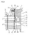
- FIG.4 is a sectional view
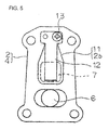
- FIG.5 is a front view viewed from the cylinder side in FIG.4
- FIG.6 is an exploded perspective view.
- reference numeral 10 is a check valve set
- 1 is a cylinder
- 2 is an passage connecting member made of heat insulating material
- 3 is a carburetor
- 4 is a passage connecting member gasket provided between the cylinder 1 and passage connecting member 2
- 5 is a carburetor gasket provided between the passage connecting member 2 and carburetor 3
- 6 is a mixture flow passage and 7 is an air flow passage in the passage connecting member 2.
- Reference numeral 1a is a flange part formed at a side of the cylinder 1 to which the passage connecting member 2 is attached.
- Reference numerals 1b and 1c are respectively an air supply chamber and a mixture passage formed in the flange part 1a.
- Reference numeral 1d is a combustion chamber in the cylinder 1
- 1e is a mixture inlet port
- 2a is a flat face of the passage connecting member 2 for connecting it to the flange part 1a
- 2b is a flat valve seat face protruded from the flat face 2a
- 11 is a leaf valve
- 12 is a stopper which is fixed to the passage connecting member 2 together with the leaf valve 11 by a screw 13.
- the leaf valve 11 and stopper 12 are fixed to the passage connecting member 2 at two holes provided at the upper part thereof, one of the holes is engaged with a locator pin 2c put in the passage connecting member 2 and the screw 13 fastens the leaf valve 11 and stopper 12 together to the passage connecting member through the other hole.
- the leaf valve 11 closes the air flow passage 7 in the insulator 2.
- the leaf valve 11 bends as shown by chain line in FIG.4 pulled by pressure difference between the air flow passage 7 and the air supply chamber 1b, and further bends pushed by dynamic pressure of air flow that occurs when the leaf valve bends and the air in the air flow passage 7 flows into the air supply chamber 1b.
- the stopper 12 restricts the bending of the leaf valve 11 to determine a maximum opening of the leaf valve 11.
- the object of the invention is to provide a crankcase compression type stratified scavenging two-stroke cycle engine provided with a check valve of simple construction for allowing scavenging air to flow only in one direction and prevent reverse flow thereof, thereby reducing the number of parts and lowering the cost of production.
- the present invention proposes a stratified scavenging two-stroke cycle engine; in which a cylinder thereof has an exhaust port and scavenge ports opening into a combustion chamber, a mixture inlet port for sucking mixture into a crank chamber when a piston moves upward toward the top dead center, and scavenging passages connecting the crank chamber to the scavenge ports; a flange part is formed at a side of the cylinder, in said flange part being formed an air supply chamber and a mixture passage; a passage connecting member having an air flow passage to be connected to the air supply chamber and a mixture flow passage to be connected to the mixture passage in the flange part of the cylinder is attached to the flange part; a gasket is located between the passage connecting member and the flange part of the cylinder; and a check valve is provided to allow air in the air flow passage in the passage connecting member to flow only toward the air supply chamber in the flange part of the cylinder; wherein said gasket is formed to have a
- a protrusion is formed in the air supply camber of the flange part of the cylinder so that a surface of the protrusion facing the leaf valve serves as a stopper of the leaf valve for restricting bending of the leaf valve when the leaf valve is bent toward the air supply chamber by pressure difference produced between the air flow passage in the passage connector member and the air supply chamber in the flange part of the cylinder.
- a stopper plate is provided behind the leaf valve part of the gasket to be fastened together with the gasket to the flange part of the cylinder.
- said gasket having integral leaf valve is larger in its outer periphery than that of the passage connecting member so that cooling air coming from the cylinder side is prevented from flowing toward the passage connecting member.
- said gasket having integral leaf valve is made of a steel plate so that proper spring characteristic is secured for the leaf valve and coated with seal material.
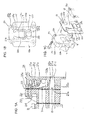
- FIG.1 A is a sectional view of the construction around the check valve according to a first embodiment of the invention
- FIG.1B is a front view viewed from the cylinder side in FIG.1A
- FIG.1C is a perspective exploded view of the construction around the check valve of FIG.1A .
- reference numeral 21 is a cylinder
- 22 is a passage connecting member made of heat insulating material
- 3 is a carburetor.
- the passage connecting member 22 has a mixture flow passage 6 and an air flow passage 7 arranged above and below.
- Reference numeral 21a is a flange part formed on a side of the cylinder 21, and 21b is a flat end face of the flange part 21a for attaching the passage connecting member 22.
- Reference numerals 21c and 21d are respectively an air supply chamber and a mixture passage formed in the flange part 21a.
- Reference numeral 23 is a gasket between the flat end face 21b of the flange part 21a of the cylinder 21 and a flat end face 22a of the passage connecting member 22.
- the gasket 23 has a leaf valve 23b integral with it so that the gasket 23 has a function as a check valve.
- Reference numeral 21e is a combustion chamber in the cylinder 21, and 21f is a mixture inlet port at an end of the mixture passage 21d.
- Reference numeral 21g is one of four screw holes tapped in the flange part 21a, 23 is a gasket integral with a leaf valve, and 24 is one of four bolts screwed into the screw hole 21g for fastening the passage connecting member 22 together with the gasket 23 to the flange part 21a of the cylinder 21.
- the mixture inlet port 21f is opened by a piston(not shown) and communicated with a crank chamber (not shown), and mixture is sucked into a crank chamber (not shown) when the piston moves upward toward the top dead center.
- the air chamber 21c is connected to a pair of scavenging passages(not shown), of which upper passages end at scavenge ports(not shown) of the cylinder and lower passages end at scavenging passage openings(not shown) opening into the crank chamber, as disclosed in the patent literature 1.
- the gasket 23 having a leaf valve 23b integral with it is shaped to have a periphery larger than the periphery of the passage connecting member 22 and that of the flange part 21a of the cylinder 21 so that the gasket 23 protrudes from the peripheries of the passage connecting member 22 and the flange part 21a as shown by 23g in FIG.1b and FIG.1C .
- the purpose of the protruded part 23g is to prevent cooling air heated by the cylinder 21 from flowing toward the passage connecting member 22 to which the carburetor 3 is attached.
- the leaf valve 23b protrudes from the upper part of the gasket 23 like a tongue in an upper opening 23e of the gasket 23.
- the upper opening 23e opens into the air supply chamber 21c of the flange part 21a.
- a lower opening 23f is provided below the upper opening 23e to open into the mixture passage 21d of the flange part 21a.
- a flat face part 22b of the flat face 22a around an opening of the air flow passage 7 of the passage connecting member 22 serves as a seat face for the leaf valve 23b formed integral with the gasket 23.
- the leaf valve 23b of the gasket 23 closes the air flow passage 7 of the passage connecting member 22.
- the leaf valve 23b bends as shown by chain line in FIG.1A pulled by pressure difference between the air flow passage 7 and the air supply chamber 21c, and further bends pushed by dynamic pressure of air flow that occurs when the leaf valve bends and the air in the air flow passage 7 flows into the air supply chamber 21c.
- the gasket 23 functions as a seal element and as a check valve which works to allow the air in the air flow passage in the passage connecting member to flow only toward the air supply chamber and prevent a reverse air flow from the air supply chamber to the air flow passage in the passage connecting member.
- the gasket 23 is fastened by four screws 24 together with the passage connecting member 22.
- Reference numeral 22c indicates one of through holes for the screw 24 to fasten the passage connecting member and gasket.
- In the gasket 23 are provided two holes 23d below the lower opening 23f symmetrical about the vertical center line of the gasket 23.
- reference numeral 22d indicates a hole in the passage connecting member 22 (see FIG.1C ) for transmitting pressure pulse for driving a fuel pump (not shown).
- Two holes 23d are provided in the gasket 23 so that one of the holes 23d coincides with the hole 22d in the passage connecting member 22 if the gasket is fitted in a reversed state.
- the gasket 23 having the leaf valve 23b is made of a thin spring steel plate, for example, a stainless steel plate in order to secure proper spring characteristic for the leaf valve 23b, and both surface of the gasket 23 are coated for example with NBR group rubber in order to increase its sealing performance. It is clear that the construction of the check valve of the present invention is extremely compact as compared with that of the prior art shown in FIG. 6 .
- FIG.2A is a sectional view
- FIG.2B is a front view viewed from the cylinder side
- FIG.2C is a perspective view of the flange part of the cylinder.
- a stopper part 21h for restricting bending of the leaf valve 23b is formed in the flange part 21a of the cylinder 21 is different from the first embodiment.
- the construction is the same as that of the first embodiment except this point.
- the stopper part 21h is more clearly recognized in FIG.2B in which it is depicted by a chain line and in FIG.1C .
- the stopper part 21h of proper thickness is formed integral with the cylinder 21 at the flange part 21a as a protrusion from the upper part thereof, and an end face thereof facing the leaf valve 23b is a curved surface to restrict bending of the leaf valve 23b to determine a maximum opening of the leaf valve 23b.
- the stopper part 21h is formed integral with the cylinder 21, the number of parts and manufacturing cost can be reduced and assembling is facilitated.
- FIG.3B is a sectional view
- FIG.3B is a front view viewed from the cylinder side.
- a stopper plate 25 for restricting bending of the leaf valve 23b is attached in the flange 21 side to be fixed together with the leaf valve 23b to the flange part 21a of the cylinder 21 and a recess 21i for receiving the stopper plate 25 is provided in the flange part of the cylinder 21 is different from the first embodiment.
- the construction is the same as that of the first embodiment except this point.
- a recess 21i is formed in the upper part of the flat end face 21b to receive the stopper plate 25 so that a surface of the stopper plate 25 facing the gasket 23 is level with the flat end face 21b of the flange part 21b of the cylinder 21.
- the stopper plate 25 is preferably made of rigid material such as a stainless steel plate thicker than the leaf valve 23b for example.
- a gasket having an integral leaf valve which works as a check valve for allowing air to flow only toward an air supply chamber connecting to scavenging passages of a stratified scavenging two-stroke cycle engine
- construction of the check valve becomes compact, and the number of parts, manufacturing cost, and assembling man-hour is facilitated can be reduced while retaining engine performance the same as that of conventional engines of this kind.
Landscapes
- Engineering & Computer Science (AREA)
- Chemical & Material Sciences (AREA)
- Combustion & Propulsion (AREA)
- Mechanical Engineering (AREA)
- General Engineering & Computer Science (AREA)
- Check Valves (AREA)
- Supercharger (AREA)
Abstract
Description
- The present invention relates to a crankcase compression type stratified scavenging two-stroke cycle engine, and more particularly to an air-ahead stratified scavenging two-stroke cycle engine.
- In crankcase compression type stratified scavenging two-stroke cycle engines, air-fuel mixture produced in a carburetor is introduced into the crank chamber and air is introduced into scavenging passages connecting scavenge ports of the cylinder to the crank chamber utilizing negative pressure produced in the crank chamber by upward movement of the piston toward the top dead center.
- On the other hand, an air-fuel mixture in the cylinder is compressed as the piston moves upward toward the top dead center.
- When the compressed mixture in the cylinder is ignited neat the top dead center, the combustion gas of the mixture increased in pressure pushes down the piston, and the combustion gas is exhausted through the exhaust port when the exhaust port is opened by the downward moving piston. Pressure in the crank chamber rises as the piston moves down toward the bottom dead center, and first the air in the scavenging passages is pushed into the cylinder through the scavenge ports of the cylinder, then the mixture in the crank chamber is pushed into the cylinder through the scavenging passages following the air pushed into the cylinder to scavenge the combustion gas in the cylinder. Thus, scavenging is first done with air and then followed by the mixture, by which blow by of mixture through the exhaust port is prevented. When the piston moves upward, the scavenge ports and exhaust port are closed by the piston and the mixture in the cylinder is compressed to be ignited near the top dead center. A stratified scavenging two-stroke cycle engine as mentioned above is disclosed in Japanese Laid-Open Patent Application No.
2001-254624 - According to the patent literature 1, as shown in
FIG.1 of the patent literature 1, a passage connecting member made of heat insulating material is provided between the cylinder and the carburetor. The carburetor has a venturi and an air passage. Mixture produced at the venturi of the carburetor is sucked by the negative pressure in the crank chamber into the crank chamber through a mixture flow passage in the passage connecting member and a mixture flow passage connecting to a mixture suction port, which port is opened by the piston when the piston moves up from the bottom dead center to be communicated with the crank chamber. Air is sucked by the negative pressure in the crank chamber through the air passage of the carburetor and an air flow passage in the passage connecting member into an air supply camber formed at a side of the cylinder, from where further into scavenging passages which are connecting to the crank chamber at their lower ends and connecting to scavenge ports in the cylinder at their upper ends. A throttle valve is provided in the venturi and an air flow control valve is provided in the air passage of the carburetor. A check valve is provided between the air flow passage in the passage connecting member and the air supply chamber at the cylinder. The check valve allows the air in the air flow passage in the passage connecting member to flow only toward the air supply chamber and prevents a reverse air flow from the air supply chamber to the air flow passage in the passage connecting member. - The check valve is a leaf valve provided to interrupt the air in the scavenging passages from flowing through the air supply chamber toward the air flow passage in the passage connecting member when the piston moves down and the air in the scavenging passages is pushed into the cylinder.
- The structure around the check valve of the stratified scavenging two-stroke engine disclosed in the patent literature 1 will be explained referring to
FIGS.4 to 6 .FIG.4 is a sectional view,FIG.5 is a front view viewed from the cylinder side inFIG.4 , andFIG.6 is an exploded perspective view. - In the drawings,
reference numeral 10 is a check valve set, 1 is a cylinder, 2 is an passage connecting member made of heat insulating material, 3 is a carburetor, 4 is a passage connecting member gasket provided between the cylinder 1 andpassage connecting member passage connecting member 2 andcarburetor 3, and 6 is a mixture flow passage and 7 is an air flow passage in thepassage connecting member 2.Reference numeral 1a is a flange part formed at a side of the cylinder 1 to which thepassage connecting member 2 is attached. Reference numerals 1b and 1c are respectively an air supply chamber and a mixture passage formed in theflange part 1a. Reference numeral 1d is a combustion chamber in thecylinder 1, 1e is a mixture inlet port, 2a is a flat face of thepassage connecting member 2 for connecting it to theflange part flat face passage connecting member 2 together with theleaf valve 11 by ascrew 13. As shown inFIGS.5 and6 , theleaf valve 11 andstopper 12 are fixed to thepassage connecting member 2 at two holes provided at the upper part thereof, one of the holes is engaged with a locator pin 2c put in thepassage connecting member 2 and thescrew 13 fastens theleaf valve 11 and stopper 12 together to the passage connecting member through the other hole. - The
leaf valve 11 closes theair flow passage 7 in theinsulator 2. When negative pressure is produced in the air supply chamber 1b, theleaf valve 11 bends as shown by chain line inFIG.4 pulled by pressure difference between theair flow passage 7 and the air supply chamber 1b, and further bends pushed by dynamic pressure of air flow that occurs when the leaf valve bends and the air in theair flow passage 7 flows into the air supply chamber 1b. - The
stopper 12 restricts the bending of theleaf valve 11 to determine a maximum opening of theleaf valve 11. - In the field of small two-stroke cycle engines improvement in engine performance and reduction in manufacturing cost are strongly demanded. The object of the invention is to provide a crankcase compression type stratified scavenging two-stroke cycle engine provided with a check valve of simple construction for allowing scavenging air to flow only in one direction and prevent reverse flow thereof, thereby reducing the number of parts and lowering the cost of production.
- To attain the object, the present invention proposes a stratified scavenging two-stroke cycle engine; in which a cylinder thereof has an exhaust port and scavenge ports opening into a combustion chamber, a mixture inlet port for sucking mixture into a crank chamber when a piston moves upward toward the top dead center, and scavenging passages connecting the crank chamber to the scavenge ports; a flange part is formed at a side of the cylinder, in said flange part being formed an air supply chamber and a mixture passage; a passage connecting member having an air flow passage to be connected to the air supply chamber and a mixture flow passage to be connected to the mixture passage in the flange part of the cylinder is attached to the flange part; a gasket is located between the passage connecting member and the flange part of the cylinder; and a check valve is provided to allow air in the air flow passage in the passage connecting member to flow only toward the air supply chamber in the flange part of the cylinder; wherein said gasket is formed to have a leaf valve formed integral with it so that the gasket functions as the gasket and the check valve.
- It is preferable that a protrusion is formed in the air supply camber of the flange part of the cylinder so that a surface of the protrusion facing the leaf valve serves as a stopper of the leaf valve for restricting bending of the leaf valve when the leaf valve is bent toward the air supply chamber by pressure difference produced between the air flow passage in the passage connector member and the air supply chamber in the flange part of the cylinder.
- It is preferable that a stopper plate is provided behind the leaf valve part of the gasket to be fastened together with the gasket to the flange part of the cylinder.
- It is preferable that said gasket having integral leaf valve is larger in its outer periphery than that of the passage connecting member so that cooling air coming from the cylinder side is prevented from flowing toward the passage connecting member.
- It is preferable that said gasket having integral leaf valve is made of a steel plate so that proper spring characteristic is secured for the leaf valve and coated with seal material.
-
-
FIG.1 A is a sectional view of the construction around the check valve according to a first embodiment of the invention. -
FIG.1B is a front view viewed from the cylinder side inFIG.1A . -
FIG.1C is a perspective exploded view of the construction around the check valve ofFIG.1A . -
FIG.2A is a sectional view of the construction around the check valve according to a second embodiment of the invention. -
FIG.2B is a front view viewed from the cylinder side inFIG.2A . -
FIG.2C is a perspective view of the flange part of the cylinder in the case of the second embodiment. -
FIG.3A is a sectional view of the construction around the check valve according to a third embodiment of the invention. -
FIG.3B is a front view viewed from the cylinder side inFIG.3A . -
FIG.4 is a sectional view of the construction around the check valve of a typical conventional stratified scavenging two-stroke engine. -
FIG.5 is a front view viewed from the cylinder side inFIG.4 . -
FIG.6 is an exploded perspective view of the construction around the check valve ofFIG.4 . - Preferred embodiments of the present invention will now be detailed with reference to the accompanying drawings. It is intended, however, that unless particularly specified, dimensions, materials, relative positions and so forth of the constituent parts in the embodiments shall be interpreted as illustrative only not as limitative of the scope of the present invention.
- A first embodiment of present invention will be explained referring to
FIGS.1A, 1B, and 1C. FIG.1 A is a sectional view of the construction around the check valve according to a first embodiment of the invention,FIG.1B is a front view viewed from the cylinder side inFIG.1A, and FIG.1C is a perspective exploded view of the construction around the check valve ofFIG.1A . - In the drawings,
reference numeral 21 is a cylinder, 22 is a passage connecting member made of heat insulating material, and 3 is a carburetor. Thepassage connecting member 22 has amixture flow passage 6 and anair flow passage 7 arranged above and below.Reference numeral 21a is a flange part formed on a side of thecylinder flange part 21a for attaching thepassage connecting member 22.Reference numerals flange part 21a. -
Reference numeral 23 is a gasket between theflat end face 21b of theflange part 21a of thecylinder 21 and aflat end face 22a of thepassage connecting member 22. - The
gasket 23 has aleaf valve 23b integral with it so that thegasket 23 has a function as a check valve. -
Reference numeral 21e is a combustion chamber in thecylinder mixture passage 21d. Reference numeral 21g is one of four screw holes tapped in theflange part passage connecting member 22 together with thegasket 23 to theflange part 21a of thecylinder 21. - The
mixture inlet port 21f is opened by a piston(not shown) and communicated with a crank chamber (not shown), and mixture is sucked into a crank chamber (not shown) when the piston moves upward toward the top dead center. Theair chamber 21c is connected to a pair of scavenging passages(not shown), of which upper passages end at scavenge ports(not shown) of the cylinder and lower passages end at scavenging passage openings(not shown) opening into the crank chamber, as disclosed in the patent literature 1. - The
gasket 23 having aleaf valve 23b integral with it is shaped to have a periphery larger than the periphery of thepassage connecting member 22 and that of theflange part 21a of thecylinder 21 so that thegasket 23 protrudes from the peripheries of thepassage connecting member 22 and theflange part 21a as shown by 23g inFIG.1b and FIG.1C . The purpose of the protruded part 23g is to prevent cooling air heated by thecylinder 21 from flowing toward thepassage connecting member 22 to which the carburetor 3 is attached. - The
leaf valve 23b protrudes from the upper part of thegasket 23 like a tongue in anupper opening 23e of thegasket 23. Theupper opening 23e opens into theair supply chamber 21c of theflange part 21a. A lower opening 23f is provided below theupper opening 23e to open into themixture passage 21d of theflange part 21a. Aflat face part 22b of theflat face 22a around an opening of theair flow passage 7 of thepassage connecting member 22 serves as a seat face for theleaf valve 23b formed integral with thegasket 23. Theleaf valve 23b of thegasket 23 closes theair flow passage 7 of thepassage connecting member 22. When negative pressure is produced in theair supply chamber 21c as the piston moves upward toward the top dead center, theleaf valve 23b bends as shown by chain line inFIG.1A pulled by pressure difference between theair flow passage 7 and theair supply chamber 21c, and further bends pushed by dynamic pressure of air flow that occurs when the leaf valve bends and the air in theair flow passage 7 flows into theair supply chamber 21c. Thus, thegasket 23 functions as a seal element and as a check valve which works to allow the air in the air flow passage in the passage connecting member to flow only toward the air supply chamber and prevent a reverse air flow from the air supply chamber to the air flow passage in the passage connecting member. - The
gasket 23 is fastened by fourscrews 24 together with thepassage connecting member 22.Reference numeral 22c indicates one of through holes for thescrew 24 to fasten the passage connecting member and gasket. In thegasket 23 are provided twoholes 23d below the lower opening 23f symmetrical about the vertical center line of thegasket 23. InFIG.1B showing thegasket 23, reference numeral 22d indicates a hole in the passage connecting member 22 (seeFIG.1C ) for transmitting pressure pulse for driving a fuel pump (not shown). Twoholes 23d are provided in thegasket 23 so that one of theholes 23d coincides with the hole 22d in thepassage connecting member 22 if the gasket is fitted in a reversed state. - The
gasket 23 having theleaf valve 23b is made of a thin spring steel plate, for example, a stainless steel plate in order to secure proper spring characteristic for theleaf valve 23b, and both surface of thegasket 23 are coated for example with NBR group rubber in order to increase its sealing performance. It is clear that the construction of the check valve of the present invention is extremely compact as compared with that of the prior art shown inFIG. 6 . - The construction around the check valve according to a second embodiment of the invention will be explained referring to
FIGS. 2A to 2C. FIG.2A is a sectional view,FIG.2B is a front view viewed from the cylinder side, andFIG.2C is a perspective view of the flange part of the cylinder. - In the second embodiment, that a
stopper part 21h for restricting bending of theleaf valve 23b is formed in theflange part 21a of thecylinder 21 is different from the first embodiment. The construction is the same as that of the first embodiment except this point. Thestopper part 21h is more clearly recognized inFIG.2B in which it is depicted by a chain line and inFIG.1C . - The
stopper part 21h of proper thickness is formed integral with thecylinder 21 at theflange part 21a as a protrusion from the upper part thereof, and an end face thereof facing theleaf valve 23b is a curved surface to restrict bending of theleaf valve 23b to determine a maximum opening of theleaf valve 23b. As thestopper part 21h is formed integral with thecylinder 21, the number of parts and manufacturing cost can be reduced and assembling is facilitated. - The construction around the check valve according to a second embodiment of the invention will be explained referring to
FIGS. 3A to 3B. FIG.3B is a sectional view, andFIG.3B is a front view viewed from the cylinder side. - In the third embodiment, that a
stopper plate 25 for restricting bending of theleaf valve 23b is attached in theflange 21 side to be fixed together with theleaf valve 23b to theflange part 21a of thecylinder 21 and a recess 21i for receiving thestopper plate 25 is provided in the flange part of thecylinder 21 is different from the first embodiment. The construction is the same as that of the first embodiment except this point. A recess 21i is formed in the upper part of theflat end face 21b to receive thestopper plate 25 so that a surface of thestopper plate 25 facing thegasket 23 is level with theflat end face 21b of theflange part 21b of thecylinder 21. Thestopper plate 25 is preferably made of rigid material such as a stainless steel plate thicker than theleaf valve 23b for example. - According to the present invention, by adopting a gasket having an integral leaf valve which works as a check valve for allowing air to flow only toward an air supply chamber connecting to scavenging passages of a stratified scavenging two-stroke cycle engine, construction of the check valve becomes compact, and the number of parts, manufacturing cost, and assembling man-hour is facilitated can be reduced while retaining engine performance the same as that of conventional engines of this kind.
Claims (5)
- A stratified scavenging two-stroke cycle engine; in which a cylinder thereof has an exhaust port and scavenge ports opening into a combustion chamber, a mixture inlet port for sucking mixture into a crank chamber when a piston moves upward toward the top dead center, and scavenging passages connecting the crank chamber to the scavenge ports; a flange part is formed at a side of the cylinder, in said flange part being formed an air supply chamber and a mixture passage; a passage connecting member having an air flow passage to be connected to the air supply chamber and a mixture flow passage to be connected to the mixture passage in the flange part of the cylinder is attached to the flange part; a gasket is located between the passage connecting member and the flange part of the cylinder; and a check valve is provided to allow air in the air flow passage in the passage connecting member to flow only toward the air supply chamber in the flange part of the cylinder; wherein said gasket is formed to have a leaf valve formed integral with it so that the gasket functions as the gasket and the check valve.
- A stratified scavenging two-stroke cycle engine according to claim 1, wherein a protrusion is formed in the air supply camber of the flange part of the cylinder so that a surface of the protrusion facing the leaf valve serves as a stopper of the leaf valve for restricting bending of the leaf valve when the leaf valve is bent toward the air supply chamber by pressure difference produced between the air flow passage in the passage connector member and the air supply chamber in the flange part of the cylinder.
- A stratified scavenging two-stroke cycle engine according to claim 1, wherein a stopper plate is provided behind the leaf valve part of the gasket to be fastened together with the gasket to the flange part of the cylinder.
- A stratified scavenging two-stroke cycle engine according to any one of claims 1 to 3, wherein said gasket having integral leaf valve is larger in its outer periphery than that of the passage connecting member so that cooling air coming from the cylinder side is prevented from flowing toward the passage connecting member.
- A stratified scavenging two-stroke cycle engine according to any one of claims 1 to 4, wherein said gasket having integral leaf valve is made of a steel plate so that proper spring characteristic is secured for the leaf valve and coated with seal material.
Applications Claiming Priority (1)
| Application Number | Priority Date | Filing Date | Title |
|---|---|---|---|
| JP2007061359A JP2008223562A (en) | 2007-03-12 | 2007-03-12 | Stratified scavenging two-stroke cycle engine |
Publications (3)
| Publication Number | Publication Date |
|---|---|
| EP1970549A2 true EP1970549A2 (en) | 2008-09-17 |
| EP1970549A3 EP1970549A3 (en) | 2013-05-29 |
| EP1970549B1 EP1970549B1 (en) | 2014-05-07 |
Family
ID=39402563
Family Applications (1)
| Application Number | Title | Priority Date | Filing Date |
|---|---|---|---|
| EP07150466.6A Active EP1970549B1 (en) | 2007-03-12 | 2007-12-28 | Stratified scavenging two-stroke cycle engine |
Country Status (4)
| Country | Link |
|---|---|
| US (1) | US7665430B2 (en) |
| EP (1) | EP1970549B1 (en) |
| JP (1) | JP2008223562A (en) |
| CN (1) | CN101265835B (en) |
Cited By (1)
| Publication number | Priority date | Publication date | Assignee | Title |
|---|---|---|---|---|
| CN108071530A (en) * | 2016-11-15 | 2018-05-25 | 川崎重工业株式会社 | Two-cycle engine |
Families Citing this family (9)
| Publication number | Priority date | Publication date | Assignee | Title |
|---|---|---|---|---|
| US7549413B1 (en) * | 2007-05-18 | 2009-06-23 | Brunswick Corporation | Flame protection gasket |
| JP5143066B2 (en) * | 2008-09-29 | 2013-02-13 | 株式会社クボタ | Multi-cylinder engine |
| JP4972665B2 (en) * | 2009-03-25 | 2012-07-11 | 株式会社クボタ | Multi-cylinder engine |
| JP5622536B2 (en) * | 2010-11-22 | 2014-11-12 | 川崎重工業株式会社 | Air-cooled engine cooling structure |
| CN102072009B (en) * | 2011-01-04 | 2012-09-05 | 山东华盛农业药械有限责任公司 | Air-guided scavenging two-stroke engine |
| US9625029B2 (en) * | 2013-09-13 | 2017-04-18 | GM Global Technology Operations LLC | Gasket with a baffle |
| US10760675B1 (en) * | 2019-06-05 | 2020-09-01 | American Axle & Manufacturing, Inc. | Assembly with gasket configured to partly form lubricant delivery channel |
| JP2020204272A (en) * | 2019-06-14 | 2020-12-24 | トヨタ自動車株式会社 | Engine cooling structure |
| EP4091889B1 (en) * | 2021-05-19 | 2024-08-28 | ZF CV Systems Europe BV | Gasket device for a pneumatic valve system in particular of a commercial vehicle |
Citations (1)
| Publication number | Priority date | Publication date | Assignee | Title |
|---|---|---|---|---|
| JP2001254624A (en) | 2000-01-07 | 2001-09-21 | Mitsubishi Heavy Ind Ltd | Stratified scavenging two-cycle engine |
Family Cites Families (9)
| Publication number | Priority date | Publication date | Assignee | Title |
|---|---|---|---|---|
| GB1303251A (en) * | 1969-03-07 | 1973-01-17 | ||
| JPH06299830A (en) * | 1993-02-17 | 1994-10-25 | Ishikawajima Shibaura Mach Co Ltd | Lubricating device of four-cycle engine |
| US5454397A (en) * | 1994-08-08 | 1995-10-03 | Fel-Pro Incorporated | Reed valve assembly and gas compressor incorporating same |
| US6257179B1 (en) | 1999-04-28 | 2001-07-10 | Mitsubishi Heavy Industries, Ltd. | Two-stroke cycle engine |
| US6591794B2 (en) * | 2000-10-24 | 2003-07-15 | Zama Japan | Air-fuel ratio control system for a stratified scavenging two-cycle engine |
| DE10064719B4 (en) * | 2000-12-22 | 2013-12-12 | Andreas Stihl Ag & Co. | Two-stroke engine with charge stratification |
| JP3517221B2 (en) * | 2001-03-16 | 2004-04-12 | 今在家精工株式会社 | Engine reed valve device |
| US6928996B2 (en) * | 2002-07-03 | 2005-08-16 | Walbro Japan, Inc. | Stratified scavenging mechanism of a two-stroke engine |
| JP4373135B2 (en) * | 2003-06-09 | 2009-11-25 | 川崎重工業株式会社 | Air scavenging type 2-cycle engine |
-
2007
- 2007-03-12 JP JP2007061359A patent/JP2008223562A/en active Pending
- 2007-12-18 US US12/000,855 patent/US7665430B2/en active Active
- 2007-12-28 EP EP07150466.6A patent/EP1970549B1/en active Active
- 2007-12-29 CN CN200710300778.4A patent/CN101265835B/en active Active
Patent Citations (1)
| Publication number | Priority date | Publication date | Assignee | Title |
|---|---|---|---|---|
| JP2001254624A (en) | 2000-01-07 | 2001-09-21 | Mitsubishi Heavy Ind Ltd | Stratified scavenging two-cycle engine |
Cited By (2)
| Publication number | Priority date | Publication date | Assignee | Title |
|---|---|---|---|---|
| CN108071530A (en) * | 2016-11-15 | 2018-05-25 | 川崎重工业株式会社 | Two-cycle engine |
| CN108071530B (en) * | 2016-11-15 | 2020-06-19 | 川崎重工业株式会社 | dual cycle engine |
Also Published As
| Publication number | Publication date |
|---|---|
| JP2008223562A (en) | 2008-09-25 |
| EP1970549A3 (en) | 2013-05-29 |
| US7665430B2 (en) | 2010-02-23 |
| EP1970549B1 (en) | 2014-05-07 |
| CN101265835A (en) | 2008-09-17 |
| CN101265835B (en) | 2010-06-16 |
| US20080223349A1 (en) | 2008-09-18 |
Similar Documents
| Publication | Publication Date | Title |
|---|---|---|
| EP1970549B1 (en) | Stratified scavenging two-stroke cycle engine | |
| CN101149031A (en) | Multi-cylinder internal combustion engine with resonator | |
| JPS5840649B2 (en) | benzouchi | |
| WO2007102428A1 (en) | Two-cycle engine | |
| WO2000065209A1 (en) | Stratified scavenging two-stroke cycle engine | |
| EP2017446B1 (en) | Laminar-scavenging two-cycle engine | |
| US20070257379A1 (en) | Carburetor | |
| JPH02204625A (en) | Two-cycle engine | |
| JP2001123841A (en) | Accelerator for two-stroke engine | |
| CN1207456A (en) | internal combustion engine piston | |
| US11821356B2 (en) | Reed valve and reed valve airbox | |
| CN107642442B (en) | Suction pipe of laminar scavenging engine | |
| JPH0236797B2 (en) | ||
| WO2008029875A1 (en) | Insulator | |
| JP5270522B2 (en) | Variable compression ratio mechanism of internal combustion engine | |
| US7975660B2 (en) | Laminated counterweight for timing control | |
| CN100338342C (en) | Two-stroke engine | |
| US3320900A (en) | Fuel pump | |
| US4926812A (en) | Cylinder head intake manifold interface | |
| JP4743559B1 (en) | Engine blow-by gas reduction device | |
| US7410153B1 (en) | Vacuum accelerator assist module for carburetors | |
| JP4580848B2 (en) | Insulator | |
| US7172178B1 (en) | Carburetor with acceleration fuel pump | |
| US10995639B1 (en) | Valve apparatus for use with a positive crankcase ventilation valve and intake manifold to enhance fuel economy of an engine | |
| US20030041818A1 (en) | Internal combustion engine fuel check valve |
Legal Events
| Date | Code | Title | Description |
|---|---|---|---|
| PUAI | Public reference made under article 153(3) epc to a published international application that has entered the european phase |
Free format text: ORIGINAL CODE: 0009012 |
|
| 17P | Request for examination filed |
Effective date: 20071228 |
|
| AK | Designated contracting states |
Kind code of ref document: A2 Designated state(s): AT BE BG CH CY CZ DE DK EE ES FI FR GB GR HU IE IS IT LI LT LU LV MC MT NL PL PT RO SE SI SK TR |
|
| AX | Request for extension of the european patent |
Extension state: AL BA HR MK RS |
|
| PUAL | Search report despatched |
Free format text: ORIGINAL CODE: 0009013 |
|
| AK | Designated contracting states |
Kind code of ref document: A3 Designated state(s): AT BE BG CH CY CZ DE DK EE ES FI FR GB GR HU IE IS IT LI LT LU LV MC MT NL PL PT RO SE SI SK TR |
|
| AX | Request for extension of the european patent |
Extension state: AL BA HR MK RS |
|
| RIC1 | Information provided on ipc code assigned before grant |
Ipc: F02B 25/22 20060101ALI20130424BHEP Ipc: F02B 25/20 20060101AFI20130424BHEP Ipc: F02B 75/02 20060101ALI20130424BHEP |
|
| GRAP | Despatch of communication of intention to grant a patent |
Free format text: ORIGINAL CODE: EPIDOSNIGR1 |
|
| INTG | Intention to grant announced |
Effective date: 20131129 |
|
| AKX | Designation fees paid |
Designated state(s): DE IT SE |
|
| GRAS | Grant fee paid |
Free format text: ORIGINAL CODE: EPIDOSNIGR3 |
|
| GRAA | (expected) grant |
Free format text: ORIGINAL CODE: 0009210 |
|
| AK | Designated contracting states |
Kind code of ref document: B1 Designated state(s): DE IT SE |
|
| RIN1 | Information on inventor provided before grant (corrected) |
Inventor name: NAKADEGAWA, DAISUKE Inventor name: UENOYAMA, KAZUYUKI Inventor name: KIMURA, TAKAHIRO Inventor name: KUDO, KAZUNORI |
|
| REG | Reference to a national code |
Ref country code: DE Ref legal event code: R096 Ref document number: 602007036465 Country of ref document: DE Effective date: 20140618 |
|
| REG | Reference to a national code |
Ref country code: SE Ref legal event code: TRGR |
|
| REG | Reference to a national code |
Ref country code: DE Ref legal event code: R097 Ref document number: 602007036465 Country of ref document: DE |
|
| PLBE | No opposition filed within time limit |
Free format text: ORIGINAL CODE: 0009261 |
|
| STAA | Information on the status of an ep patent application or granted ep patent |
Free format text: STATUS: NO OPPOSITION FILED WITHIN TIME LIMIT |
|
| 26N | No opposition filed |
Effective date: 20150210 |
|
| REG | Reference to a national code |
Ref country code: DE Ref legal event code: R097 Ref document number: 602007036465 Country of ref document: DE Effective date: 20150210 |
|
| PGFP | Annual fee paid to national office [announced via postgrant information from national office to epo] |
Ref country code: SE Payment date: 20161213 Year of fee payment: 10 |
|
| REG | Reference to a national code |
Ref country code: DE Ref legal event code: R082 Ref document number: 602007036465 Country of ref document: DE Representative=s name: KOHLER SCHMID MOEBUS PATENTANWAELTE PARTNERSCH, DE Ref country code: DE Ref legal event code: R081 Ref document number: 602007036465 Country of ref document: DE Owner name: MITSUBISHI HEAVY INDUSTRIES MEIKI ENGINES CO.,, JP Free format text: FORMER OWNER: MITSUBISHI HEAVY INDUSTRIES, LTD., TOKYO, JP |
|
| PG25 | Lapsed in a contracting state [announced via postgrant information from national office to epo] |
Ref country code: SE Free format text: LAPSE BECAUSE OF NON-PAYMENT OF DUE FEES Effective date: 20171229 |
|
| PGFP | Annual fee paid to national office [announced via postgrant information from national office to epo] |
Ref country code: DE Payment date: 20251104 Year of fee payment: 19 |
|
| PGFP | Annual fee paid to national office [announced via postgrant information from national office to epo] |
Ref country code: IT Payment date: 20251121 Year of fee payment: 19 |