EP1970303A2 - Rib element and composite flange for aircraft - Google Patents
Rib element and composite flange for aircraft Download PDFInfo
- Publication number
- EP1970303A2 EP1970303A2 EP08152587A EP08152587A EP1970303A2 EP 1970303 A2 EP1970303 A2 EP 1970303A2 EP 08152587 A EP08152587 A EP 08152587A EP 08152587 A EP08152587 A EP 08152587A EP 1970303 A2 EP1970303 A2 EP 1970303A2
- Authority
- EP
- European Patent Office
- Prior art keywords
- flange
- reinforcing component
- corner
- composite
- edge
- Prior art date
- Legal status (The legal status is an assumption and is not a legal conclusion. Google has not performed a legal analysis and makes no representation as to the accuracy of the status listed.)
- Withdrawn
Links
- 239000002131 composite material Substances 0.000 title claims abstract description 61
- 230000003014 reinforcing effect Effects 0.000 claims abstract description 94
- 239000003381 stabilizer Substances 0.000 claims description 10
- 239000000835 fiber Substances 0.000 claims description 6
- 239000011230 binding agent Substances 0.000 claims description 5
- 239000000853 adhesive Substances 0.000 claims description 4
- 230000001070 adhesive effect Effects 0.000 claims description 4
- 230000009467 reduction Effects 0.000 description 6
- 230000002787 reinforcement Effects 0.000 description 5
- 238000004519 manufacturing process Methods 0.000 description 4
- 239000000463 material Substances 0.000 description 4
- 238000000034 method Methods 0.000 description 3
- RTAQQCXQSZGOHL-UHFFFAOYSA-N Titanium Chemical compound [Ti] RTAQQCXQSZGOHL-UHFFFAOYSA-N 0.000 description 2
- 239000003292 glue Substances 0.000 description 2
- 229910052751 metal Inorganic materials 0.000 description 2
- 239000002184 metal Substances 0.000 description 2
- 239000011347 resin Substances 0.000 description 2
- 229920005989 resin Polymers 0.000 description 2
- 238000009745 resin transfer moulding Methods 0.000 description 2
- 239000003351 stiffener Substances 0.000 description 2
- 239000010936 titanium Substances 0.000 description 2
- 229910052719 titanium Inorganic materials 0.000 description 2
- 229910000838 Al alloy Inorganic materials 0.000 description 1
- OKTJSMMVPCPJKN-UHFFFAOYSA-N Carbon Chemical compound [C] OKTJSMMVPCPJKN-UHFFFAOYSA-N 0.000 description 1
- 239000004411 aluminium Substances 0.000 description 1
- 229910052782 aluminium Inorganic materials 0.000 description 1
- XAGFODPZIPBFFR-UHFFFAOYSA-N aluminium Chemical compound [Al] XAGFODPZIPBFFR-UHFFFAOYSA-N 0.000 description 1
- 239000004760 aramid Substances 0.000 description 1
- 229920003235 aromatic polyamide Polymers 0.000 description 1
- 229910052799 carbon Inorganic materials 0.000 description 1
- 230000000694 effects Effects 0.000 description 1
- 239000011152 fibreglass Substances 0.000 description 1
- 239000004033 plastic Substances 0.000 description 1
- 230000008719 thickening Effects 0.000 description 1
Images

Classifications
-
- B—PERFORMING OPERATIONS; TRANSPORTING
- B64—AIRCRAFT; AVIATION; COSMONAUTICS
- B64C—AEROPLANES; HELICOPTERS
- B64C3/00—Wings
- B64C3/18—Spars; Ribs; Stringers
-
- B—PERFORMING OPERATIONS; TRANSPORTING
- B64—AIRCRAFT; AVIATION; COSMONAUTICS
- B64C—AEROPLANES; HELICOPTERS
- B64C3/00—Wings
- B64C3/18—Spars; Ribs; Stringers
- B64C3/187—Ribs
-
- B—PERFORMING OPERATIONS; TRANSPORTING
- B64—AIRCRAFT; AVIATION; COSMONAUTICS
- B64C—AEROPLANES; HELICOPTERS
- B64C1/00—Fuselages; Constructional features common to fuselages, wings, stabilising surfaces or the like
-
- B—PERFORMING OPERATIONS; TRANSPORTING
- B64—AIRCRAFT; AVIATION; COSMONAUTICS
- B64C—AEROPLANES; HELICOPTERS
- B64C5/00—Stabilising surfaces
-
- F—MECHANICAL ENGINEERING; LIGHTING; HEATING; WEAPONS; BLASTING
- F16—ENGINEERING ELEMENTS AND UNITS; GENERAL MEASURES FOR PRODUCING AND MAINTAINING EFFECTIVE FUNCTIONING OF MACHINES OR INSTALLATIONS; THERMAL INSULATION IN GENERAL
- F16B—DEVICES FOR FASTENING OR SECURING CONSTRUCTIONAL ELEMENTS OR MACHINE PARTS TOGETHER, e.g. NAILS, BOLTS, CIRCLIPS, CLAMPS, CLIPS OR WEDGES; JOINTS OR JOINTING
- F16B2200/00—Constructional details of connections not covered for in other groups of this subclass
- F16B2200/50—Flanged connections
-
- Y—GENERAL TAGGING OF NEW TECHNOLOGICAL DEVELOPMENTS; GENERAL TAGGING OF CROSS-SECTIONAL TECHNOLOGIES SPANNING OVER SEVERAL SECTIONS OF THE IPC; TECHNICAL SUBJECTS COVERED BY FORMER USPC CROSS-REFERENCE ART COLLECTIONS [XRACs] AND DIGESTS
- Y10—TECHNICAL SUBJECTS COVERED BY FORMER USPC
- Y10T—TECHNICAL SUBJECTS COVERED BY FORMER US CLASSIFICATION
- Y10T403/00—Joints and connections
- Y10T403/51—Joints and connections including spaced, diverse connections
Definitions
- the invention relates to a rib element for use in support structures for wings, guide surfaces, and stabilizers of aircraft, the rib element being manufactured from a composite material and comprising flanges interconnected with one another at rounded corners.
- the invention further relates to a composite flange for use in structures of aircraft, the composite flange comprising at least two interconnected flanges and a rounded corner between the flanges.
- a wing of aircraft such as aeroplanes and the like, comprises skin plates, between which the actual support structure of the wing resides, the support structure typically comprising a front spar and a rear spar in the longitudinal direction of the wing and wing ribs provided in the transverse direction of the wing to connect the front and rear spars. Further, a plurality of stringers is usually provided between the wing ribs and the skin plates.
- the structure of stabilizers as well as of guide surfaces, such as spoilers, flaps, rudders, etc., is typically similar to that of a wing and comprises rib elements comparable with wing ribs.
- a known way to try and reduce the weight of a flange structure is to make the thickness of the flanges to be reduced over a distance starting from the corner, leaving the corner with a sufficient thickness of material.
- General design rules for composite structures determine that a change in thickness should not take place discontinuously but a reduction in thickness is to take place gradually. Generally, the change in thickness/length ratio should be 1/20. This means that, while taking the design rules into account, the relatively large thickness of the flanges required by the corner cannot be reduced sufficiently in order to make the structure lighter. The problem is thus that the current solutions do not enable a sufficiently strong and yet light flange structure to be produced, although such features are extremely important properties for aircraft components.
- An object of the present invention is to provide a novel and improved rib element for aircraft, and a composite flange for use in aircraft.
- the rib element according to the invention is characterized in that at least one reinforcing component manufactured in a separate phase with respect to the rib element is attached to the rib element; and that the reinforcing component is arranged in the corner between the flanges of the rib element and is arranged to cover at least a part of the inner corner, the reinforcing component being arranged to reinforce said corner.
- the composite flange according to the invention is characterized in that at least one reinforcing component manufactured in a separate phase with respect to the composite flange is attached to the composite flange; and that the reinforcing component is arranged to cover at least a part of the inner corner of the composite flange, the reinforcing component being arranged to reinforce the corner of the composite flange.
- An idea underlying the invention is that a corner of a rib element or another flange structure manufactured from a composite material is reinforced by a reinforcing component attached to the area of an inner corner between two longitudinal flanges.
- the reinforcing component is arranged to cover the entire inner corner or at least a part thereof.
- An advantage of the invention is that the flanges constituting a corner may be thinner since the reinforcing component makes the corner stronger.
- the strength of the corner no longer depends entirely on the thickness of the flanges. Any additional weight incurred by the reinforcing component is small compared to a reduction in weight achieved when being able to use thinner flanges.
- the properties, material, dimensions, and attachment of a separately manufactured reinforcing component may be selected in a versatile manner as necessary. Further, in terms of manufacturing techniques, such a reinforcing component is simple to attach to the flange structure compared, for instance, with creating reductions in thickness according to the design rules.
- the reinforcing component is made of a composite, comprising at least one polymeric binder and at least one reinforcing fibre.
- a reinforcing component has a particularly good strength/weight ratio.
- the reinforcing component is attached by an adhesive to a composite flange.
- the reinforcing component is also capable of receiving shear forces to which the flange is subjected.
- a first flange comprises an attachment point, and that the reinforcing component is made to extend from the corner at least as far as to said attachment point. This enables the reinforcing component to easily receive loads to which the attachment point is subjected. Furthermore, the reinforcing component constitutes a thickening portion in the thin flange for the attachment point, which is advantageous particularly when the attachment point is provided with a hole through which an attachment bolt is arranged. It is also possible that the first flange is glued to a structure to be supported, in which case the entire outer surface of the first flange serves as an attachment point. In such a case, the reinforcing component may extend as far as to the outer edge of the first flange.
- the reinforcing component is an elongated plate having a longitudinal first edge and a longitudinal second edge. Furthermore, the second edge of the reinforcing component is curved and its radius of curvature substantially corresponds to that of an inner corner of a composite flange. The reinforcing component is attached to the first flange and arranged so that the second edge of the reinforcing component resides against the inner corner of the composite flange.
- the reinforcing component is an elongated curved piece wherein the radius of curvature of an outer surface of the component substantially corresponds with the radius of curvature of the inner corner of the composite flange.
- the outer surface of the curved reinforcing component is glued to the inner corner of the composite flange.
- the thickness of the reinforcing component equals or is less than the radius of curvature of the inner corner.
- the reinforcing component is made of metal, such as aluminium alloy or titanium.
- the reinforcing component comprises one or more holes to make it lighter.
- the rib element or the composite flange i.e. the flange structure
- the superimposed reinforcing components may be equal in size or they may reduce in size in one or more directions, the more the farther away from the inner surface of the flange structure the reinforcing components reside.
- An idea of an embodiment is that the size of the angle of the corner is between 75° and 105°.
- the rib element and the composite flange comprise at least one flange which comprises a section over which its thickness is arranged to be reduced as seen away from the corner.
- Such reduction in thickness may be implemented according to the normal design rules, e.g. with a 1/20 ratio.
- the structure then becomes particularly light as, on account of the reinforcing component, the flanges constituting the corner maybe thin and as the flanges have further been made thinner over a distance starting from the corner.
- Figure 1 schematically shows an aircraft wing whose support structure comprises a plurality of rib elements
- Figure 2 schematically shows an aircraft tail provided with stabilizers and guide surfaces whose support structure may comprise a plurality of rib elements
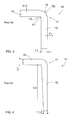
- Figure 3 is a schematic view showing, as seen from the longitudinal direction, a prior art flange wherein strength of a corner is ensured by making the flanges relatively thick,
- Figure 4 is a schematic view showing, as seen from the longitudinal direction, another prior art flange wherein thickness of a vertical flange has been made to be reduced downwards, towards a free edge, in order to reduce weight,
- Figure 5 is a schematic view showing, as seen from the longitudinal direction, a composite flange according to the invention.
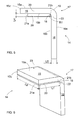
- Figure 6 is a schematic and perspective view showing another composite flange according to the invention.
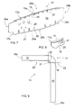
- Figure 7 is a schematic and perspective view showing a rib element according to the invention.
- Figure 8 schematically shows a detail of a corner between a vertical flange and a horizontal flange of the rib element according to Figure 7 .
- Figure 9 schematically further shows a third composite flange and a reinforcing component provided at a corner according to the invention.
- Figure 1 shows a wing 1 attached to a fuselage 2 of an aircraft.
- a trailing edge of the wing 1 may be provided with movable guide surfaces 3a to 3c.
- the wing 1 may comprise an upper skin plate 4a and a lower skin plate 4b, a support structure of the wing being provided therebetween, which may comprise a front spar 5 and a rear spar 6 as well as a plurality of wing ribs 7 arranged between the spars.
- the front and the rear spars 5, 6 constitute stiffeners substantially in the longitudinal direction of the wing
- the wing ribs 7 constitute stiffeners in the transverse direction of the wing.
- the support structure may further comprise a plurality of stringers 8 which may be attached to an inner surface of the skin plates 4a and 4b and to the wing ribs 7.
- a wing rib 7 may be a rib element according to the invention.
- Figure 2 shows an aircraft tail provided with fixed stabilizers 12a, 13a and movable guide surfaces 12b, 13b.
- the support structures of these stabilizers and guide surfaces may be provided with a rib element according to the invention.
- Figure 3 shows a typical composite flange 14 comprising a first flange 15 and a second flange 16 interconnected with one another such that they constitute a corner 17. Since the structure in question is a composite structure, the corner 17 is rounded. The corner 17 comprises an inner corner 18 and an outer corner 19. The radius of the inner corner 18 is R1 while the radius of the outer corner is R2. To be on the safe side, a thickness L1 of the flanges 15, 16 is usually made sufficiently large so that no risk of the corner 17 collapsing exists. Therefore, the weight of the composite flange is relatively large. Typically, the corner 17 is subjected to opening forces F1 which try to increase the angle of the corner 17.
- Figure 4 shows a composite flange 14 wherein an attempt has been made to make its vertical flange 16 lighter according to the design rules for composite structures by using a "ramp" for reducing the thickness.
- the thickness L1 of the flanges 15, 16 has to be relatively large in order to ensure the strength of the corner 17.
- Figure 5 shows an application of the invention wherein the corner 17 of the composite flange 14 is reinforced and strengthened by means of a reinforcing component 20 attached against an inner surface 15b of the first flange 15.
- a reinforcing component 20 may be an elongated plate-like piece having a longitudinal first edge 21 a and a longitudinal second edge 21 b.
- the second edge 21 b may have a curved shape such that its radius of curvature substantially corresponds with the radius of curvature R1 of the inner corner 18 of the corner 17.
- the reinforcing component 20 is arranged such that the curved second edge 21 b resides against the inner corner 18.
- a thickness L4 of the reinforcing component 20 may selected such that the second edge 21 b covers the entire corner area 22 or, alternatively, at least a part thereof.
- the thickness L4 of the reinforcing component 20 is smaller than a thickness L5 of the flanges 15, 16, but in some cases the situation may be the opposite.
- the thickness L4 of the reinforcing component 20 may be selected such that it is larger than the corner area 22, in which case the second edge 21 b of the reinforcing component 20 may also comprise a straight section over a distance, which extends over the corner area 22 and settles against an inner surface 16b of the second flange.
- the weight of the reinforcing component 20 is clearly larger, which, the component being an aircraft component, is disadvantageous.
- Figure 5 further shows that the first flange 15 may be equipped with an attachment point 23 to which some other component belonging to the aircraft may be attached by glue, rivets, bolts or another appropriate means.
- the attachment point 23 may be provided with a hole for an attachment bolt.
- the reinforcing component 20 may extend from the corner 17 at least as far as to the attachment point 23, typically some distance over the attachment point 23 or even as far as to a free outer edge 15c of the first flange 15.
- the reinforcing component 20 may be glued against the inner surface 15b of the first flange, so it is capable of receiving shear stresses towards the attachment point in a plane direction.
- the attachment point 23 is also thicker, which, of course, strengthens the walls of the attachment hole.
- the reinforcing component 20 is relatively thin, in which case its curved second edge 21 b only covers a part of the corner area 22 of the inner corner 18. Further, the uniform portion of the entire upper surface 15b of the first flange 15 may serve as an attachment point 23, which may be attached by an adhesive to some other component of the aircraft. In such a case, the reinforcing component may in a width direction L7 extend as far as to the outer edge 15c of the first flange 15.
- Figure 7 shows an elongated rib element 24 provided with longitudinal curved sides 25a and 25b equipped with a first flange 15 and a third flange 26 whose outer surfaces 15a, 26a are arrangeable towards the skin plates of a wing, guide surface or stabilizer.
- a second flange 16 is provided between the flanges 15, 26, whereby a first corner 17a resides between the first flange 15 and the second flange while a second corner 17b resides between the third flange 26 and the second flange 16.
- the first and the third flanges 15, 26 are substantially horizontal while the second flange 16 is substantially vertical.
- the angle of the corner 17a, 17b may also be other than a right angle, e.g.
- the longitudinal corners 17a, 17b comprise rounded inner corners and rounded outer corners.
- the curved sides may be provided with notches 27 which may divide the flanges 15, 26 into two or more parts and also extend a distance into the vertical flange 16.
- An attachment member for a stringer for example, may be arranged in these notches 27.
- the vertical flange 16 may further be provided with one or more openings 28 for pipes, wires or the like, and it may further be provided with a manhole for service and assembly.
- the rib element 24 is further provided with transverse ends 29a, 29b in the second flange 16, the ends being arrangeable towards the edge spars of a wing, guide surface or stabilizer.
- reinforcing components 20 are only provided in the first corners 17a, but of course it is possible to arrange reinforcing components in the second corners 17b as well. Further, when necessary, different reinforcing components 20 may be used in different corners of the rib element 24.
- the features and properties disclosed in the description of the previous Figures 5 and 6 as well as of the following Figure 9 may also be applied to the rib element 24.
- Figure 8 shows a detail of a corner between the vertical flange and the horizontal flange of the rib element according to Figure 7 .
- the corner 17 between the flanges 15, 16 is reinforced by attaching a longitudinal curved reinforcing component 20 to the corner 17 so that it covers, partly or completely, the corner area 23.
- the reinforcing component 20 comprises an outer surface 30 whose radius of curvature substantially corresponds with the radius of curvature R1 of the inner corner 18 of the composite flange.
- the outer surface 30 may be attached by glue to the inner corner 18 of the composite flange.
- the reinforcing component 20 may be a relatively thin structure, in which case its inner surface 31 may reside at the corner 17.
- Such a reinforcing component 20 may be made of a composite or it may be made e.g. of aluminium or titanium. Further, starting from the corner 17, the reinforcing component 20 may extend a distance towards the free edge 15c of the first flange 15 and, correspondingly, a distance towards the free edge 16c of the second flange 16.
- the aforementioned reinforcing components may comprise one or more openings to lighten the structure of the reinforcing component.
- a composite structure may comprise a plurality of parallel reinforcing fibres.
- One or more such layers of reinforcing fibres may be provided.
- the orientation of the reinforcing fibres may be the same or it may be different.
- the composite structure may comprise a netlike fibre reinforcement in one or more layers.
- a resin or another suitable plastic material for instance, may serve as a binder.
- a fibre glass, carbon fibre, aramid fibre or the like, for example, may serve as a fibre reinforcement.
- the composite parts such as the composite flange, rib element and reinforcing components, may each be manufactured separately using e.g. Resin Transfer Moulding.
- RTM method is suitable for manufacturing dimensionally accurate components.
- the reinforcements or reinforcement preforms are inserted in a mould and the mould is closed. Next, the mould may be injected with resin or a corresponding binder. Further, a Prepreg material, i.e. a pre-impregnated reinforcement, which may be hardened in an autoclave, may also be used.
- the features disclosed in the present application may be used as such, irrespective of other features.
- the features disclosed in the present application may be combined so as to provide different combinations.
Landscapes
- Engineering & Computer Science (AREA)
- Aviation & Aerospace Engineering (AREA)
- Mechanical Engineering (AREA)
- Moulding By Coating Moulds (AREA)
- Connection Of Plates (AREA)
Abstract
Description
- The invention relates to a rib element for use in support structures for wings, guide surfaces, and stabilizers of aircraft, the rib element being manufactured from a composite material and comprising flanges interconnected with one another at rounded corners. The invention further relates to a composite flange for use in structures of aircraft, the composite flange comprising at least two interconnected flanges and a rounded corner between the flanges. The field of the invention is described in closer detail in the preambles of the independent claims.
- A wing of aircraft, such as aeroplanes and the like, comprises skin plates, between which the actual support structure of the wing resides, the support structure typically comprising a front spar and a rear spar in the longitudinal direction of the wing and wing ribs provided in the transverse direction of the wing to connect the front and rear spars. Further, a plurality of stringers is usually provided between the wing ribs and the skin plates. The structure of stabilizers as well as of guide surfaces, such as spoilers, flaps, rudders, etc., is typically similar to that of a wing and comprises rib elements comparable with wing ribs.
- In modern aircraft, more and more structural parts manufactured from a composite material are used instead of conventional components manufactured from metal parts that have been riveted together. The use of composite materials enables the weight of the structures to be reduced. It is also possible to manufacture various flange structures from a composite material wherein two or more flanges constitute an angle with respect to one another. A composite material is known to be stiff yet fragile, so to be on the safe side, every effort is made to dimension a corner of a flange structure such that it is extremely stiff. Consequently, the flanges are made quite thick, which results in a heavy flange structure. A known way to try and reduce the weight of a flange structure is to make the thickness of the flanges to be reduced over a distance starting from the corner, leaving the corner with a sufficient thickness of material. General design rules for composite structures, however, determine that a change in thickness should not take place discontinuously but a reduction in thickness is to take place gradually. Generally, the change in thickness/length ratio should be 1/20. This means that, while taking the design rules into account, the relatively large thickness of the flanges required by the corner cannot be reduced sufficiently in order to make the structure lighter. The problem is thus that the current solutions do not enable a sufficiently strong and yet light flange structure to be produced, although such features are extremely important properties for aircraft components.
- An object of the present invention is to provide a novel and improved rib element for aircraft, and a composite flange for use in aircraft.
- The rib element according to the invention is characterized in that at least one reinforcing component manufactured in a separate phase with respect to the rib element is attached to the rib element; and that the reinforcing component is arranged in the corner between the flanges of the rib element and is arranged to cover at least a part of the inner corner, the reinforcing component being arranged to reinforce said corner.
- The composite flange according to the invention is characterized in that at least one reinforcing component manufactured in a separate phase with respect to the composite flange is attached to the composite flange; and that the reinforcing component is arranged to cover at least a part of the inner corner of the composite flange, the reinforcing component being arranged to reinforce the corner of the composite flange.
- An idea underlying the invention is that a corner of a rib element or another flange structure manufactured from a composite material is reinforced by a reinforcing component attached to the area of an inner corner between two longitudinal flanges. The reinforcing component is arranged to cover the entire inner corner or at least a part thereof.
- An advantage of the invention is that the flanges constituting a corner may be thinner since the reinforcing component makes the corner stronger. The strength of the corner no longer depends entirely on the thickness of the flanges. Any additional weight incurred by the reinforcing component is small compared to a reduction in weight achieved when being able to use thinner flanges. Furthermore, the properties, material, dimensions, and attachment of a separately manufactured reinforcing component may be selected in a versatile manner as necessary. Further, in terms of manufacturing techniques, such a reinforcing component is simple to attach to the flange structure compared, for instance, with creating reductions in thickness according to the design rules.
- An idea of an embodiment is that the reinforcing component is made of a composite, comprising at least one polymeric binder and at least one reinforcing fibre. Such a reinforcing component has a particularly good strength/weight ratio.
- An idea of an embodiment is that the reinforcing component is attached by an adhesive to a composite flange. In such a case, the reinforcing component is also capable of receiving shear forces to which the flange is subjected.
- An idea of an embodiment is that a first flange comprises an attachment point, and that the reinforcing component is made to extend from the corner at least as far as to said attachment point. This enables the reinforcing component to easily receive loads to which the attachment point is subjected. Furthermore, the reinforcing component constitutes a thickening portion in the thin flange for the attachment point, which is advantageous particularly when the attachment point is provided with a hole through which an attachment bolt is arranged. It is also possible that the first flange is glued to a structure to be supported, in which case the entire outer surface of the first flange serves as an attachment point. In such a case, the reinforcing component may extend as far as to the outer edge of the first flange.
- An idea of an embodiment is that the reinforcing component is an elongated plate having a longitudinal first edge and a longitudinal second edge. Furthermore, the second edge of the reinforcing component is curved and its radius of curvature substantially corresponds to that of an inner corner of a composite flange. The reinforcing component is attached to the first flange and arranged so that the second edge of the reinforcing component resides against the inner corner of the composite flange.
- An idea of an embodiment is that the reinforcing component is an elongated curved piece wherein the radius of curvature of an outer surface of the component substantially corresponds with the radius of curvature of the inner corner of the composite flange. The outer surface of the curved reinforcing component is glued to the inner corner of the composite flange.
- An idea of an embodiment is that the thickness of the reinforcing component equals or is less than the radius of curvature of the inner corner. On the basis of study conducted, it has been observed that even a surprisingly thin reinforcing component increases the strength of the corner significantly.
- An idea of an embodiment is that the reinforcing component is made of metal, such as aluminium alloy or titanium.
- An idea of an embodiment is that the reinforcing component comprises one or more holes to make it lighter.
- An idea of an embodiment is that the rib element or the composite flange, i.e. the flange structure, comprises two or more reinforcing components arranged on top of one another and attached to the side of the inner surface of the flange structure. The superimposed reinforcing components may be equal in size or they may reduce in size in one or more directions, the more the farther away from the inner surface of the flange structure the reinforcing components reside.
- An idea of an embodiment is that the size of the angle of the corner is between 75° and 105°.
- An idea of an embodiment is that the rib element and the composite flange comprise at least one flange which comprises a section over which its thickness is arranged to be reduced as seen away from the corner. Such reduction in thickness may be implemented according to the normal design rules, e.g. with a 1/20 ratio. The structure then becomes particularly light as, on account of the reinforcing component, the flanges constituting the corner maybe thin and as the flanges have further been made thinner over a distance starting from the corner.
- Some embodiments of the invention are described in closer detail in the accompanying drawings, in which
-
Figure 1 schematically shows an aircraft wing whose support structure comprises a plurality of rib elements, -
Figure 2 schematically shows an aircraft tail provided with stabilizers and guide surfaces whose support structure may comprise a plurality of rib elements, -
Figure 3 is a schematic view showing, as seen from the longitudinal direction, a prior art flange wherein strength of a corner is ensured by making the flanges relatively thick, -
Figure 4 is a schematic view showing, as seen from the longitudinal direction, another prior art flange wherein thickness of a vertical flange has been made to be reduced downwards, towards a free edge, in order to reduce weight, -
Figure 5 is a schematic view showing, as seen from the longitudinal direction, a composite flange according to the invention, -
Figure 6 is a schematic and perspective view showing another composite flange according to the invention, -
Figure 7 is a schematic and perspective view showing a rib element according to the invention, -
Figure 8 schematically shows a detail of a corner between a vertical flange and a horizontal flange of the rib element according toFigure 7 , and -
Figure 9 schematically further shows a third composite flange and a reinforcing component provided at a corner according to the invention. - For the sake of clarity, the figures show some embodiments of the invention in a simplified manner. In the figures, like reference numbers identify like elements.
-
Figure 1 shows a wing 1 attached to afuselage 2 of an aircraft. A trailing edge of the wing 1 may be provided with movable guide surfaces 3a to 3c. The wing 1 may comprise anupper skin plate 4a and alower skin plate 4b, a support structure of the wing being provided therebetween, which may comprise afront spar 5 and a rear spar 6 as well as a plurality ofwing ribs 7 arranged between the spars. Thus, the front and the rear spars 5, 6 constitute stiffeners substantially in the longitudinal direction of the wing, whereas thewing ribs 7 constitute stiffeners in the transverse direction of the wing. The support structure may further comprise a plurality ofstringers 8 which may be attached to an inner surface of theskin plates wing ribs 7. Awing rib 7 may be a rib element according to the invention. -
Figure 2 shows an aircraft tail provided with fixedstabilizers -
Figure 3 shows a typicalcomposite flange 14 comprising afirst flange 15 and asecond flange 16 interconnected with one another such that they constitute acorner 17. Since the structure in question is a composite structure, thecorner 17 is rounded. Thecorner 17 comprises aninner corner 18 and anouter corner 19. The radius of theinner corner 18 is R1 while the radius of the outer corner is R2. To be on the safe side, a thickness L1 of theflanges corner 17 collapsing exists. Therefore, the weight of the composite flange is relatively large. Typically, thecorner 17 is subjected to opening forces F1 which try to increase the angle of thecorner 17. -
Figure 4 shows acomposite flange 14 wherein an attempt has been made to make itsvertical flange 16 lighter according to the design rules for composite structures by using a "ramp" for reducing the thickness. This means that the reduction in thickness from the thickness L1 to a thickness L2 may only take place at a ratio determined by the design rules to a distance L3. For instance, the ratio may be 1/20, in which case the thickness of the flanges may become reduced by 1 mm over a distance of 20 mm. Since the reduction in thickness has to take place carefully, it does not always have the desired effect on the weight of the structure. Within the region of thecorner 17, however, the thickness L1 of theflanges corner 17. -
Figure 5 shows an application of the invention wherein thecorner 17 of thecomposite flange 14 is reinforced and strengthened by means of a reinforcingcomponent 20 attached against aninner surface 15b of thefirst flange 15. There may be one reinforcingcomponent 20, or two or more reinforcingcomponents 20 may be arranged on top of one another to constitute a laminate structure. The reinforcingcomponent 20 may be an elongated plate-like piece having a longitudinalfirst edge 21 a and a longitudinalsecond edge 21 b. Thesecond edge 21 b may have a curved shape such that its radius of curvature substantially corresponds with the radius of curvature R1 of theinner corner 18 of thecorner 17. The reinforcingcomponent 20 is arranged such that the curvedsecond edge 21 b resides against theinner corner 18. A thickness L4 of the reinforcingcomponent 20 may selected such that thesecond edge 21 b covers theentire corner area 22 or, alternatively, at least a part thereof. Usually the thickness L4 of the reinforcingcomponent 20 is smaller than a thickness L5 of theflanges component 20 may be selected such that it is larger than thecorner area 22, in which case thesecond edge 21 b of the reinforcingcomponent 20 may also comprise a straight section over a distance, which extends over thecorner area 22 and settles against aninner surface 16b of the second flange. In such a case, however, the weight of the reinforcingcomponent 20 is clearly larger, which, the component being an aircraft component, is disadvantageous. The strength studies conducted surprisingly revealed that even a rather thin reinforcingcomponent 20 is capable of supporting thecorner 17 significantly. Consequently, the thickness L5 of thebasic flanges -
Figure 5 further shows that thefirst flange 15 may be equipped with anattachment point 23 to which some other component belonging to the aircraft may be attached by glue, rivets, bolts or another appropriate means. Theattachment point 23 may be provided with a hole for an attachment bolt. The reinforcingcomponent 20 may extend from thecorner 17 at least as far as to theattachment point 23, typically some distance over theattachment point 23 or even as far as to a freeouter edge 15c of thefirst flange 15. The reinforcingcomponent 20 may be glued against theinner surface 15b of the first flange, so it is capable of receiving shear stresses towards the attachment point in a plane direction. On account of the reinforcingcomponent 20, theattachment point 23 is also thicker, which, of course, strengthens the walls of the attachment hole. - In the solution shown in
Figure 6 , the reinforcingcomponent 20 is relatively thin, in which case its curvedsecond edge 21 b only covers a part of thecorner area 22 of theinner corner 18. Further, the uniform portion of the entireupper surface 15b of thefirst flange 15 may serve as anattachment point 23, which may be attached by an adhesive to some other component of the aircraft. In such a case, the reinforcing component may in a width direction L7 extend as far as to theouter edge 15c of thefirst flange 15. -
Figure 7 shows anelongated rib element 24 provided with longitudinalcurved sides first flange 15 and athird flange 26 whoseouter surfaces second flange 16 is provided between theflanges first corner 17a resides between thefirst flange 15 and the second flange while asecond corner 17b resides between thethird flange 26 and thesecond flange 16. In the case shown inFigure 7 , the first and thethird flanges second flange 16 is substantially vertical. Of course, the angle of thecorner longitudinal corners notches 27 which may divide theflanges vertical flange 16. An attachment member for a stringer, for example, may be arranged in thesenotches 27. Thevertical flange 16 may further be provided with one ormore openings 28 for pipes, wires or the like, and it may further be provided with a manhole for service and assembly. Therib element 24 is further provided withtransverse ends second flange 16, the ends being arrangeable towards the edge spars of a wing, guide surface or stabilizer. In the solution according toFigure 7 , reinforcingcomponents 20 are only provided in thefirst corners 17a, but of course it is possible to arrange reinforcing components in thesecond corners 17b as well. Further, when necessary, different reinforcingcomponents 20 may be used in different corners of therib element 24. The features and properties disclosed in the description of the previousFigures 5 and 6 as well as of the followingFigure 9 may also be applied to therib element 24. -
Figure 8 shows a detail of a corner between the vertical flange and the horizontal flange of the rib element according toFigure 7 . - In
Figure 9 , thecorner 17 between theflanges component 20 to thecorner 17 so that it covers, partly or completely, thecorner area 23. The reinforcingcomponent 20 comprises anouter surface 30 whose radius of curvature substantially corresponds with the radius of curvature R1 of theinner corner 18 of the composite flange. Theouter surface 30 may be attached by glue to theinner corner 18 of the composite flange. The reinforcingcomponent 20 may be a relatively thin structure, in which case itsinner surface 31 may reside at thecorner 17. Such a reinforcingcomponent 20 may be made of a composite or it may be made e.g. of aluminium or titanium. Further, starting from thecorner 17, the reinforcingcomponent 20 may extend a distance towards thefree edge 15c of thefirst flange 15 and, correspondingly, a distance towards thefree edge 16c of thesecond flange 16. - The aforementioned reinforcing components may comprise one or more openings to lighten the structure of the reinforcing component.
- It is to be generally noted that a composite structure may comprise a plurality of parallel reinforcing fibres. One or more such layers of reinforcing fibres may be provided. In different layers, the orientation of the reinforcing fibres may be the same or it may be different. Alternatively, the composite structure may comprise a netlike fibre reinforcement in one or more layers. A resin or another suitable plastic material, for instance, may serve as a binder. A fibre glass, carbon fibre, aramid fibre or the like, for example, may serve as a fibre reinforcement.
- The composite parts, such as the composite flange, rib element and reinforcing components, may each be manufactured separately using e.g. Resin Transfer Moulding. RTM method is suitable for manufacturing dimensionally accurate components. The reinforcements or reinforcement preforms are inserted in a mould and the mould is closed. Next, the mould may be injected with resin or a corresponding binder. Further, a Prepreg material, i.e. a pre-impregnated reinforcement, which may be hardened in an autoclave, may also be used.
- In some cases, the features disclosed in the present application may be used as such, irrespective of other features. On the other hand, when necessary, the features disclosed in the present application may be combined so as to provide different combinations.
- The drawings and the related description are only intended to illustrate the idea of the invention. The details of the invention may vary within the scope of the claims.
Claims (10)
- A rib element for aircraft, which is an elongated support component to be arranged in a space defined by skin plates and edge spars in a wing, guide surface or stabilizer of the aircraft and which comprises:longitudinal curved sides (25a, 25b) provided with at least one first flange (15) and at least one third (26) flange whose outer surfaces (15a, 26a) are arrangeable towards the skin plates of a wing, guide surface or stabilizer;a second flange (16) to which the transverse first flange (15) and second flange (26) are connected in a longitudinal corner (17a, 17b) and in a predetermined angle position;rounded inner corners (18) and rounded outer corners (19) in corners (17) between the flanges;transverse ends (29a, 29b) in the second flange (16) which are arrangeable towards the edge spars of a wing, guide surface or stabilizer;and which rib element (24) is manufactured from a composite material,characterized in that
at least one reinforcing component (20) manufactured in a separate phase with respect to the rib element is attached to the rib element (24); and
the reinforcing component (20) is arranged in the corner (17) between the flanges (15, 16, 26) of the rib element (24) and is arranged to cover at least a part of the inner corner (18), the reinforcing component (20) being arranged to reinforce said corner (17). - A rib element as claimed in claim 1, characterized in that
the transverse flange (15, 26) comprises at least one attachment point (23) at a distance from the inner corner (18);
the reinforcing component (20) comprises a longitudinal first edge (21a) on a side of a free edge (15a, 26a) of the transverse flange (15, 26) and a longitudinal second edge (21b) on a side of the inner corner (18);
the reinforcing component (20) is dimensioned such that its first edge (21a) resides at a greater distance from the inner corner (18) than said attachment point (23); and
the reinforcing component (20) is attached by an adhesive against an inner surface (15b, 26b) of the transverse flange, the reinforcing component (20) being arranged to receive shear forces to which the attachment point (23) is subjected and to support the corner (17). - A rib element as claimed in claim 1 or 2, characterized in that
the reinforcing component (20) is an elongated plate-like piece provided with a longitudinal first edge (21 a) and a longitudinal second edge (21 b);
the second edge (21 b) of the reinforcing component (20) is curved and its radius of curvature substantially corresponds with a radius of curvature (R1) of the inner corner (18);
the reinforcing component (20) is attached to the first flange (15) and arranged so that the second edge (21 b) of the reinforcing component resides against the inner corner (18); and
a thickness (L4) of the reinforcing component (20) is smaller than the radius of curvature (R1) of the inner corner. - A rib element as claimed in claim 1 or 2, characterized in that
the reinforcing component (20) is an elongated curved piece attached to the inner corner (18) of the rib element. - An aircraft composite flange,
which comprises at least a longitudinal first flange (15) and a longitudinal second flange (16), each having one longitudinal free edge (15c, 16c) and being interconnected with one another in a longitudinal corner (17) in a predetermined angle position;
and in which corner (17) a rounded inner corner (18) and a rounded outer corner (19) are provided between the flanges (15, 16);
and which composite flange (14) is manufactured at least mainly from at least one polymeric binder and at least one reinforcing fibre;
characterized in that
at least one reinforcing component (20) manufactured in a separate phase with respect to the composite flange is attached to the composite flange (14); and
the reinforcing component (20) is arranged to cover at least a part of the inner corner (18) of the composite flange (14), the reinforcing component being arranged to reinforce the corner (17) of the composite flange. - A composite flange as claimed in claim 5, characterized in that
the reinforcing component (20) is made of a composite comprising at least one polymeric binder and at least one reinforcing fibre. - A composite flange as claimed in claim 5 or 6, character- ized in that
the reinforcing component (20) is attached by an adhesive to the composite flange (14). - A composite flange as claimed in any preceding claim 5 to 7, characterized in that
the first flange (15) comprises at least one attachment point (23); and
the reinforcing component (20) is dimensioned to extend from the corner (17) at least as far as to said attachment point (23). - A composite flange as claimed in any preceding claim 5 to 8, characterized in that
the reinforcing component (20) is an elongated plate-like piece provided with a longitudinal first edge (21 a) and a longitudinal second edge (21 b);
the second edge (21 b) of the reinforcing component is curved and its radius of curvature substantially corresponds with a radius of curvature (R1) of the inner corner (18) of the composite flange; and
the reinforcing component (20) is attached to the first flange (15) and arranged so that the second edge (21 b) of the reinforcing component resides against the inner corner (18) of the composite flange. - A composite flange as claimed in any preceding claim 5 to 8, characterized in that
the reinforcing component (20) is an elongated curved piece, the radius of curvature of an outer surface (30) of which substantially corresponds with the radius of curvature (R1) of the inner corner (18) of the composite flange; and
the outer surface (30) of the curved reinforcing component is glued to the inner corner (18) of the composite flange.
Applications Claiming Priority (1)
| Application Number | Priority Date | Filing Date | Title |
|---|---|---|---|
| FI20075172A FI119979B (en) | 2007-03-12 | 2007-03-12 | Arc elements and composite flange for aircraft |
Publications (2)
| Publication Number | Publication Date |
|---|---|
| EP1970303A2 true EP1970303A2 (en) | 2008-09-17 |
| EP1970303A3 EP1970303A3 (en) | 2015-11-18 |
Family
ID=37930083
Family Applications (1)
| Application Number | Title | Priority Date | Filing Date |
|---|---|---|---|
| EP08152587.5A Withdrawn EP1970303A3 (en) | 2007-03-12 | 2008-03-11 | Rib element and composite flange for aircraft |
Country Status (3)
| Country | Link |
|---|---|
| US (1) | US7967248B2 (en) |
| EP (1) | EP1970303A3 (en) |
| FI (1) | FI119979B (en) |
Cited By (1)
| Publication number | Priority date | Publication date | Assignee | Title |
|---|---|---|---|---|
| WO2012082252A1 (en) * | 2010-12-14 | 2012-06-21 | The Boeing Company | Skew-angle radius filler to reduce the risk of delamination of a laminated stringer assembly |
Families Citing this family (20)
| Publication number | Priority date | Publication date | Assignee | Title |
|---|---|---|---|---|
| GB0606079D0 (en) * | 2006-03-27 | 2006-05-03 | Airbus Uk Ltd | Aircraft component |
| GB0611875D0 (en) * | 2006-06-15 | 2006-07-26 | Airbus Uk Ltd | A stringer for an aircraft wing and a method of forming thereof |
| FR2903732B1 (en) * | 2006-07-12 | 2008-09-12 | Airbus France Sas | AIR INTAKE FOR AIRCRAFT TURBOKER. |
| DE102008002117B4 (en) * | 2008-05-30 | 2013-10-31 | Airbus Operations Gmbh | Composite and structure |
| ES2372828B1 (en) * | 2008-12-17 | 2012-12-13 | Airbus Operations, S.L. | RIB-HARDWARE. |
| FR2975970B1 (en) * | 2011-05-30 | 2013-05-17 | Aircelle Sa | TOGETHER FOR AN AIRCRAFT NACELLE |
| US9149997B2 (en) | 2012-09-14 | 2015-10-06 | United Technologies | Composite flange from braided preform |
| US8535042B1 (en) | 2012-09-14 | 2013-09-17 | General Electric Company | Apparatus for manufacturing a flanged component and methods of manufacturing the same |
| US20140119904A1 (en) | 2012-11-01 | 2014-05-01 | United Technologies Corporation | In-situ pressure enhanced processing of composite articles |
| GB2528078B (en) * | 2014-07-08 | 2020-07-29 | Airbus Operations Ltd | Structure |
| GB2528076B (en) * | 2014-07-08 | 2020-07-29 | Airbus Operations Ltd | Rib foot |
| US10196126B2 (en) | 2015-04-07 | 2019-02-05 | The Boeing Company | Rib structure and method of forming thereof |
| GB201522327D0 (en) * | 2015-12-17 | 2016-02-03 | Airbus Operations Ltd | Wing structure |
| US10196937B2 (en) | 2015-12-30 | 2019-02-05 | General Electric Company | Method and system for improving structural characteristics of composite component corners |
| GB2575102A (en) * | 2018-06-29 | 2020-01-01 | Airbus Operations Ltd | Duct stringer with bulkhead |
| US11180238B2 (en) * | 2018-11-19 | 2021-11-23 | The Boeing Company | Shear ties for aircraft wing |
| US20200331616A1 (en) * | 2019-04-19 | 2020-10-22 | Goodrich Corporation | Bonded structural rib for heated aircraft leading edge |
| USD1067200S1 (en) | 2020-12-18 | 2025-03-18 | Hitachi Energy Ltd | Flange for fastening, supporting, or mounting |
| CN114233732B (en) * | 2021-12-15 | 2024-02-27 | 北京机科国创轻量化科学研究院有限公司 | An adhesive composite material connector and a method for connecting composite panels using the same |
| US12466538B1 (en) * | 2024-07-10 | 2025-11-11 | The Boeing Company | Airfoil coupling systems and methods |
Family Cites Families (13)
| Publication number | Priority date | Publication date | Assignee | Title |
|---|---|---|---|---|
| US1363569A (en) * | 1920-07-08 | 1920-12-28 | Adoniram J Cook | Metal aeroplane |
| US1796654A (en) * | 1927-11-07 | 1931-03-17 | Hermann Otto | Metallic aeroplane wing |
| US2140558A (en) * | 1938-06-03 | 1938-12-20 | Schmidt Karl | Airplane fabric attachment |
| US2427853A (en) * | 1944-02-23 | 1947-09-23 | Curtiss Wright Corp | Aircraft construction |
| US2397447A (en) * | 1944-10-19 | 1946-03-26 | Budd Edward G Mfg Co | Metallic structure |
| US2567124A (en) * | 1946-05-10 | 1951-09-04 | Curtiss Wright Corp | Airfoil construction |
| US5233129A (en) * | 1992-10-15 | 1993-08-03 | At&T Bell Laboratories | Seismic network bay frame |
| ES2168027B1 (en) | 1998-12-18 | 2003-10-01 | Airbus Espana Sl | A REMOVAL AND / OR FIXED TRACTION-COMPRESSION UNION PROCEDURE FOR APPLICATION TO COMPOSITE MATERIALS. |
| US6190484B1 (en) * | 1999-02-19 | 2001-02-20 | Kari Appa | Monolithic composite wing manufacturing process |
| GB0022589D0 (en) * | 2000-09-14 | 2000-11-01 | Bae Systems Plc | Composite joints |
| JP4574086B2 (en) * | 2001-09-03 | 2010-11-04 | 富士重工業株式会社 | Method for manufacturing composite wing and composite wing |
| GB0609166D0 (en) * | 2006-05-09 | 2006-06-21 | Airbus Uk Ltd | Apparatus for and method of inhibiting delamination |
| US7735600B2 (en) * | 2006-12-08 | 2010-06-15 | The Boeing Corporation | Monolithic acoustically-treated engine nacelle inlet panels |
-
2007
- 2007-03-12 FI FI20075172A patent/FI119979B/en not_active IP Right Cessation
-
2008
- 2008-03-06 US US12/074,857 patent/US7967248B2/en not_active Expired - Fee Related
- 2008-03-11 EP EP08152587.5A patent/EP1970303A3/en not_active Withdrawn
Non-Patent Citations (1)
| Title |
|---|
| None |
Cited By (5)
| Publication number | Priority date | Publication date | Assignee | Title |
|---|---|---|---|---|
| WO2012082252A1 (en) * | 2010-12-14 | 2012-06-21 | The Boeing Company | Skew-angle radius filler to reduce the risk of delamination of a laminated stringer assembly |
| CN103261022A (en) * | 2010-12-14 | 2013-08-21 | 波音公司 | Skew-angle radius filler to reduce the risk of delamination of a laminated stringer assembly |
| JP2014506213A (en) * | 2010-12-14 | 2014-03-13 | ザ・ボーイング・カンパニー | Skew angle radius filler to reduce the risk of delamination in laminated stringer assemblies |
| US8679616B2 (en) | 2010-12-14 | 2014-03-25 | The Boeing Company | Skew-angle radius filler |
| CN103261022B (en) * | 2010-12-14 | 2016-09-28 | 波音公司 | Reduce the inclination angle radius filler of the risk of delamination of lamination stringer assembly |
Also Published As
| Publication number | Publication date |
|---|---|
| US7967248B2 (en) | 2011-06-28 |
| FI20075172A0 (en) | 2007-03-12 |
| FI20075172L (en) | 2008-09-13 |
| EP1970303A3 (en) | 2015-11-18 |
| US20080223987A1 (en) | 2008-09-18 |
| FI119979B (en) | 2009-05-29 |
Similar Documents
| Publication | Publication Date | Title |
|---|---|---|
| US7967248B2 (en) | Rib element and composite flange for aircraft | |
| EP2066563B1 (en) | Curved element, wing, control surface and stabilizer for aircraft | |
| US7806367B2 (en) | Integrated multispar torsion box of composite material | |
| US8434719B2 (en) | Leading edge element of aircraft, method for manufacturing one, wing and stabilizer | |
| CN104245295B (en) | With the hat reinforcement for tilting web and the method for forming hat reinforcement | |
| EP2487106B1 (en) | Composite material structure, as well as aircraft wing and fuselage provided therewith | |
| EP1818255B1 (en) | Fastening arrangement for an aircraft | |
| US10131418B2 (en) | Flow body with a load introduction element integrated therein, method for manufacturing a flow body, and aircraft with such a flow body | |
| US6386481B1 (en) | Arrangement for fastening stringers to aircraft wing ribs | |
| KR102024396B1 (en) | Lower joints between outboard wing boxes and center wing sections of aircraft wing assemblies | |
| EP2589531B1 (en) | Internal structure of aircraft made of composite material | |
| US8876049B2 (en) | Section of aircraft fuselage in composite material with a constant internal profile | |
| EP2905220A1 (en) | Laminated I-blade stringer | |
| EP3095691A1 (en) | Multi-spar torsion box structure | |
| EP2671793B1 (en) | Torsion box for an aircraft stiffened with non-parallel stringers | |
| EP2698241B1 (en) | Highly integrated inner structure of a torsion box of an aircraft lifting surface and method of producing it | |
| US11124285B2 (en) | Aerodynamic/hydrodynamic profile with a composite reinforced oblong foam core | |
| US20220289358A1 (en) | Composite structures for aerodynamic components | |
| EP2738086B1 (en) | A main supporting structure of an aircraft lifting surface | |
| EP3835038B1 (en) | Trailing edge for a composite multispar integrated lifting surface and method for manufacturing said trailing edge | |
| US20120267479A1 (en) | Method for the production of a composite trailing edge panel for an aircraft element | |
| US11623733B2 (en) | Bead-stiffened movable surfaces | |
| EP3787885B1 (en) | Method for making a shear web flange |
Legal Events
| Date | Code | Title | Description |
|---|---|---|---|
| PUAI | Public reference made under article 153(3) epc to a published international application that has entered the european phase |
Free format text: ORIGINAL CODE: 0009012 |
|
| AK | Designated contracting states |
Kind code of ref document: A2 Designated state(s): AT BE BG CH CY CZ DE DK EE ES FI FR GB GR HR HU IE IS IT LI LT LU LV MC MT NL NO PL PT RO SE SI SK TR |
|
| AX | Request for extension of the european patent |
Extension state: AL BA MK RS |
|
| PUAL | Search report despatched |
Free format text: ORIGINAL CODE: 0009013 |
|
| AK | Designated contracting states |
Kind code of ref document: A3 Designated state(s): AT BE BG CH CY CZ DE DK EE ES FI FR GB GR HR HU IE IS IT LI LT LU LV MC MT NL NO PL PT RO SE SI SK TR |
|
| AX | Request for extension of the european patent |
Extension state: AL BA MK RS |
|
| RIC1 | Information provided on ipc code assigned before grant |
Ipc: B64C 3/18 20060101AFI20151012BHEP |
|
| AKY | No designation fees paid | ||
| AXX | Extension fees paid |
Extension state: AL Extension state: MK Extension state: BA Extension state: RS |
|
| REG | Reference to a national code |
Ref country code: DE Ref legal event code: R108 |
|
| STAA | Information on the status of an ep patent application or granted ep patent |
Free format text: STATUS: THE APPLICATION IS DEEMED TO BE WITHDRAWN |
|
| 18D | Application deemed to be withdrawn |
Effective date: 20160519 |