EP1969305B1 - Position and torque sensor - Google Patents
Position and torque sensor Download PDFInfo
- Publication number
- EP1969305B1 EP1969305B1 EP06734368.1A EP06734368A EP1969305B1 EP 1969305 B1 EP1969305 B1 EP 1969305B1 EP 06734368 A EP06734368 A EP 06734368A EP 1969305 B1 EP1969305 B1 EP 1969305B1
- Authority
- EP
- European Patent Office
- Prior art keywords
- array
- magnetic
- sensor
- arrays
- field
- Prior art date
- Legal status (The legal status is an assumption and is not a legal conclusion. Google has not performed a legal analysis and makes no representation as to the accuracy of the status listed.)
- Active
Links
Images

Classifications
-
- G—PHYSICS
- G01—MEASURING; TESTING
- G01D—MEASURING NOT SPECIALLY ADAPTED FOR A SPECIFIC VARIABLE; ARRANGEMENTS FOR MEASURING TWO OR MORE VARIABLES NOT COVERED IN A SINGLE OTHER SUBCLASS; TARIFF METERING APPARATUS; MEASURING OR TESTING NOT OTHERWISE PROVIDED FOR
- G01D5/00—Mechanical means for transferring the output of a sensing member; Means for converting the output of a sensing member to another variable where the form or nature of the sensing member does not constrain the means for converting; Transducers not specially adapted for a specific variable
- G01D5/12—Mechanical means for transferring the output of a sensing member; Means for converting the output of a sensing member to another variable where the form or nature of the sensing member does not constrain the means for converting; Transducers not specially adapted for a specific variable using electric or magnetic means
- G01D5/244—Mechanical means for transferring the output of a sensing member; Means for converting the output of a sensing member to another variable where the form or nature of the sensing member does not constrain the means for converting; Transducers not specially adapted for a specific variable using electric or magnetic means influencing characteristics of pulses or pulse trains; generating pulses or pulse trains
- G01D5/245—Mechanical means for transferring the output of a sensing member; Means for converting the output of a sensing member to another variable where the form or nature of the sensing member does not constrain the means for converting; Transducers not specially adapted for a specific variable using electric or magnetic means influencing characteristics of pulses or pulse trains; generating pulses or pulse trains using a variable number of pulses in a train
- G01D5/2451—Incremental encoders
- G01D5/2452—Incremental encoders incorporating two or more tracks having an (n, n+1, ...) relationship
-
- G—PHYSICS
- G01—MEASURING; TESTING
- G01L—MEASURING FORCE, STRESS, TORQUE, WORK, MECHANICAL POWER, MECHANICAL EFFICIENCY, OR FLUID PRESSURE
- G01L3/00—Measuring torque, work, mechanical power, or mechanical efficiency, in general
- G01L3/02—Rotary-transmission dynamometers
- G01L3/04—Rotary-transmission dynamometers wherein the torque-transmitting element comprises a torsionally-flexible shaft
- G01L3/10—Rotary-transmission dynamometers wherein the torque-transmitting element comprises a torsionally-flexible shaft involving electric or magnetic means for indicating
- G01L3/101—Rotary-transmission dynamometers wherein the torque-transmitting element comprises a torsionally-flexible shaft involving electric or magnetic means for indicating involving magnetic or electromagnetic means
- G01L3/104—Rotary-transmission dynamometers wherein the torque-transmitting element comprises a torsionally-flexible shaft involving electric or magnetic means for indicating involving magnetic or electromagnetic means involving permanent magnets
Definitions
- the present invention relates to field sensors and, in particular, to magnetic sensors for determining position and torque.
- Magnetic sensing for determining a position or speed of a moving component is known and is used in applications such as power steering, braking, and motor control systems.
- Motor position sensing and steering wheel position sensing are similar in at least one way: access to the end of the moving shaft is generally limited or non-existent because the end of the shaft is connected to operating components.
- sensing is usually performed at the side of the shaft.
- a target magnet positioned on a shaft can be detected with a magnetic sensing element or sensor positioned concentric to the longitudinal axis of the shaft.
- the sensor may include components configured to count the number of times the shaft rotates.
- the position of the shaft may be determined using several target magnets.
- Resolvers and encoders are often used to process the raw information generated by the magnetic components. Resolvers provide an absolute output signal and encoders provide a relative output signal. The absolute nature of the signal from a resolver is desirable, but resolvers are often complex and expensive. Encoders are, in general, simpler and cheaper than resolvers, but can be inaccurate. In some cases, error detection hardware is used with encoders, but this adds complexity.
- US 2003/0145663 A1 discloses a sensor including three multi-pole wheels and three sensor elements. Each sensor element is positioned opposite from one of the multi-pole wheels.
- WO 89/05540 A1 discloses a rotating electrical machine or motor.
- WO 02/16879 A1 discloses a torque angle sensor including two code wheels and four sensor elements. Each code wheel includes an upper code track and a lower code track. One sensor element is positioned above the upper code track of code wheel, two sensor elements are positioned between the lower code track of code wheel and the upper code track of code wheel, and one sensor element is positioned below the lower code track of code wheel.
- US 2002/0118011 A1 discloses several low carbon ferrous plates.
- a magnet 14 is located at each end of a ferrous plate.
- the invention provides for a relative angular displacement sensor.
- the sensor also includes a magnetic field direction sensor element, such as an anisotropic magnetoresistive (“AMR”) sensor, positioned above and between the first array and the second array.
- AMR anisotropic magnetoresistive
- the sensor may be used in different relative angular displacement sensing applications.
- the first array may be positioned on an input shaft of a steering torque sensing assembly and the second array may be positioned on an output shaft.
- the field sensor may be located to sense the relative angular position between the two arrays and ultimately the relative angular position of one shaft with respect to the other.
- the invention provides for an absolute position sensor.
- the absolute position sensor includes a second array of N magnetic pole pairs, where N is a positive number.
- the sensor also includes a first array of M magnetic pole pairs, where M is a positive number equal to N-1 array N+ 1.
- the second array is arranged substantially in parallel to the first array, and mechanically coupled to the first array.
- the sensor also includes a magnetic field direction sensor element, such as an AMR sensor, positioned above and between the first array and the second array.
- the sensor may be used in different absolute position sensing applications.
- the mechanically coupled first and second arrays may be positioned on a steering shaft with a field sensor located between the two arrays to sense the absolute rotational position of the steering shaft.
- the invention provides an absolute angular position and relative angular displacement sensor.
- the absolute angular position and relative angular displacement sensor includes a first array of magnetic pole pairs, a second array of magnetic pole pairs and a third array of magnetic pole pairs, arranged substantially in parallel to, and mechanically coupled to the second array.
- a first field sensor is positioned above and between the first array and the second array, and a second field sensor is positioned above and between the second and third array.
- the first and second field sensors may be an AMR sensor or an array of AMR sensors.
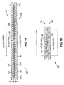
- Fig. 1A illustrates an exemplary absolute linear position sensing system 100.
- the absolute linear position sensing system 100 includes a first magnetic array 105, a second magnetic array 110, and a magnetic field or field sensor 115.
- the field sensor may be a type of magnetoresistive sensor such as an AMR sensor. An array of AMR sensors can also be used.
- the first magnetic array 105 and second magnetic array 110 are mechanically coupled to each other to move as a single unit.
- the field sensor 115 is positioned between the magnetic arrays 105 and 110, and senses a differential magnetic field created between the two arrays 105 and 110, as described in greater detail below.
- the position sensing system 100 can also include processing components (such as those shown in Fig. 5 ), which are capable of receiving and processing signals from the field sensor 115.
- the first magnetic array 105 includes "N" magnetic pole pairs. Each pole pair includes a north pole 120 and a south pole 125.
- the second magnetic array 110 includes "M" magnetic pole pairs. M is a number that is different from N, which can be equal to N+1 or N-1. In the embodiment shown, M is equal to N+1.
- the magnetic pole pairs of the second magnetic array 110 also include north and south poles, designated with reference numerals 127 and 129. Although, it is possible to align at least one magnetic pole in the second magnetic array 110 to a corresponding and opposite magnetic pole in the first magnetic array 105, the difference in the number of poles (e.g., either N+1 or N-1) in the second array 110 creates a misalignment between the other poles.
- This pole misalignment creates a differential magnetic field direction 130 N which varies proportionally with position along the face of the magnetic array. In other words, the field between the arrays changes orientation in respect to position.
- the differential magnetic field direction 130 N between each of the opposite poles of the magnetic arrays 105 and 110 is unique and discrete, and is established according to the +1 difference in pole spacing between each magnetic array. The unique nature of the field direction allows positional sensing to be accomplished using a field sensor, as is described in more detail below.
- the magnetic arrays 105 and 110 are spaced apart a distance D, but positioned substantially parallel to one another.
- the magnetic arrays should be positioned sufficiently close to one another to create a field that can be detected by the field sensor 115.
- the magnetic field strength of each magnet in the arrays 105 and 110 is a consideration in determining the distance between the arrays. In general, the stronger the magnets used in the arrays, the larger the distance D between the arrays may be. In one embodiment, the distance D is approximately 1 millimeter ("mm"). In other embodiments, the arrays may be positioned closer or farther apart.
- the field sensor 115 is positioned between and spaced from the arrays 105 and 110. In the embodiment shown, the field sensor 115 is positioned above the arrays a certain distance. In one embodiment, this distance is 1.7 mm. However, it is possible to locate the field sensor 115 at different distances and in a position that is adjacent to the arrays, but not above them.
- the magnetic field sensor measures the angle of the magnetic field direction 130 N . As the first and second magnetic arrays 105 and 110 change position with respect to the field sensor 115, the magnetic field 130 N alternates between 0 and 0 + 180 with each pole pair.
- the field angle ⁇ shifts linearly from a minimum level of - ⁇ at a null point, to a maximum of + ⁇ when the null point is reached at an opposing end of the magnetic arrays 105 and 110 where -90 ⁇ ⁇ 90.
- the orientation of the field lines for the differential magnetic field 130 N shown in Fig. 1A represents the approximate magnetic fields between the two magnetic arrays 105 and 110.
- the field sensor 115 can take the form of an AMR sensor or array of AMR sensors. Some AMR sensors can not detect the difference between a field angle of ⁇ and that of ⁇ + 180. As a result, when such AMR sensors are used, the output of the magnetic field sensor 115 is not affected by the alternating polarity changes, or the changing boundary conditions at the north and south pole interfaces.
- an AMR sensor can be configured to detect the absolute field angle difference described above.
- the field sensor 115 is a four-element sin/cos AMR sensor. The four elements provide a device that bridges the length of a single magnetic pole on the magnetic array 105 and 110.
- the discrete value of ⁇ can be used as an indication of position along the length of the magnetic arrays 105 and 110.
- Using an AMR field sensor whose output is averaged over a sufficient distance can help to avoid magnetic field dropouts or losses that are caused by field variations (e.g., changing boundary conditions at north and south pole interfaces).
- Fig. 1B illustrates an exemplary absolute angular position sensing system 150.
- the absolute angular position sensing system 150 includes a first magnetic array 155, a second magnetic array 160, and a magnetic field or field sensor 165, such as an AMR sensor or array of AMR sensors.
- the first magnetic array 155, and second magnetic array 160 are mechanically coupled to each other moving as a single unit.
- the field sensor 165 is positioned between the magnetic arrays 155 and 160, and senses a differential magnetic field 170 created between the two arrays 155 and 160, as described in greater detail below.
- the absolute angular position sensing system 150 can also include processing components (such as those shown in Fig. 5 ), which are capable of receiving and processing signals from the field sensor 165.
- the components function to provide a magnetic field direction that changes in proportion to rotary position.
- the function of the magnetic arrays and field angle sensor are substantially identical to that more fully described in the absolute linear position sensing embodiment, Fig. 1A .
- Figs. 2A and 2B illustrate a relative angular displacement sensing system 200, shown assembled as part of a larger device such as steering torque sensing system.
- the relative angular displacement sensing system 200 includes a first magnetic array 205, a second magnetic array 210, and a magnetic field or field sensor 215.
- An input shaft 220 and an output shaft 225 are separated by a torque coupling 230.
- the torque coupling 230 is designed to flex when a torque is applied to either shaft, resulting in an angular displacement between the input shaft 220 and output shaft 225 in proportion to the applied torsional load.
- the first magnetic array 205 includes 12 magnetic pole pairs, which alternate between a north pole 235 and a south pole 240. However, in other embodiments, more magnetic pole pairs can be used. In the embodiment shown, the first magnetic array 205 is attached or coupled to the input shaft 220.
- the second magnetic array 210 also includes 12 magnetic poles pairs, which alternate between a north pole 235 and a south pole 240.
- the second magnetic array 210 is attached or coupled to the output shaft 225, and is generally aligned with the first magnetic array 205, as shown in Fig. 2A .
- the field sensor 215, similar to the field sensor 115 shown in Figs. 1A is positioned between the first and second magnetic field arrays 205 and 210, and therefore, the input and output shafts 220 and 225.
- the poles of the magnetic arrays 205 and 210 are directly aligned to one another.
- the orientation of the magnetic fields 245 between the arrays 205 and 210 are also generally aligned (e.g., the magnetic field lines 245 are generally parallel to the arrays 205 and 210).
- the input shaft 220 and the output shaft 225 become misaligned about the torque coupling 230, causing the magnetic arrays 205 and 210 to shift with respect to one another.
- the direction of the magnetic fields 245 also change.
- the magnetic field direction changes described above can be measured using the field sensor 215. For example, as long as the shafts 220 and 225 and the magnetic arrays 205 and 210 do not shift with respect to one another, the average value of ⁇ between each of the corresponding poles in the magnetic arrays 205 and 210 remains constant. However, when the input shaft 220 rotates, the field angle is shifted (e.g., alternates between ⁇ and ⁇ + 180). That field angle is measured using the field sensor 215 to provide an indication of the relative angular displacement of the input shaft and the output shaft which is proportional to the amount of torque applied. Measuring relative position in this way can be useful for a variety of applications.
- the torque created at the steering wheel shaft during maneuvers can be inferred by measuring the relative position change between two torsionally coupled shaft segments.
- the torque created within an electric motor or transmission can be inferred in a similar manner.
- the field sensor 215 is used to measure the direction change in the magnetic field 245, providing a direct measurement of the angular displacement of the two shafts which is proportional to the amount of torque that is being applied.
- the angle orientation is the same between all of the corresponding poles between the magnetic arrays 205 and 210. The exact rotational position of the shafts 220 and 225 is generally immaterial to the measurement of torque.
- the maximum measurement range in the relative angular displacement embodiment is inversely dependent on the quantity of pole pairs within the magnetic array. The greater the number of pole pairs the smaller the full scale measurement range and visa versa. This relationship can be defined as follows:
- the magnetic arrays 205 and 210 each include 12 pole pairs providing a maximum angular measurement range equal to 30 degrees.
- Small differences in spacing between the opposing pole pairs of the magnetic arrays 205 and 210 may generate noise as the orientation of the magnetic field 245 between the corresponding poles varies across the field sensor 215.
- This noise can increase as the difference between opposing pole pair spacing increases.
- the noise error on the torque signal is approximately 2/24 or +/- 0.083 degrees.
- this error can be reduced by increasing the number of pole pairs in each of the magnetic arrays. In some embodiments, there are 24 pole pairs, but the number of pole pairs may range between about 12 and 36 for typical applications.
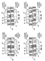
- FIGs. 3A-3D illustrate computer models 300, 305, 310, and 315, respectively, of a relative angular displacement sensor as would be employed as part of a larger device such as a steering torque sensing system.
- Each of the models includes an input shaft 320 that is separated from an output shaft 325 by an elastic torque coupling 330.
- the input shaft 320 and output shaft 325 each include a magnetic array 335 and 340, respectively.
- each of the magnetic arrays 335 and 340 includes the same number of pole pairs.
- a four-element AMR sensor array 345 that bridges across the dimension of one pole is positioned above the magnetic arrays 335 and 340. Magnetic field vectors are illustrated by arrows (grouped by dashed line 350).
- the primary magnetic field direction is perpendicular to the axis of rotation.
- the magnetic field vectors 350 in the plane of the AMR sensor array 345 are generally perpendicular along the length of the array.
- the computer model 300 was generated using twelve pole pairs for each of the magnetic arrays 335 and 340, although arrays with other numbers of pole pairs can be used.
- the poles of the magnetic arrays 335 and 340 shown in the model 305 are not aligned and are displaced with respect to each other. This type of angular displacement can occur, for example, when a torque is applied to the input shaft 320.
- the angular displacement of the magnetic arrays 335 and 340 creates a proportional change in the magnetic field vectors 350.
- the magnetic field vectors in the plane of AMR sensor array change across the face of the array.
- the average of this change is proportional to the angular displacement of magnetic arrays 335 and 340.
- a 2.5 degree angular displacement (i.e., mechanical angle) of magnetic arrays 335 and 340 results in a 7.5 degree average magnetic field angle.
- a 5 degree angular displacement results in a 17.5 degree average magnetic field angle
- a 7.5 degree angular displacement results in a 30.5 degree average magnetic field angle, respectively.
- the relationship between angular displacement and average magnetic field angle can be different.
- the models 300-315 generally illustrate that the displacement of two multi-pole magnets in proximity to each other creates a differential magnetic field vector direction that changes in relationship to the angular displacement of the magnetic arrays with respect to each other. Additionally, the average of the absolute value of the differential magnetic field direction in the plane parallel to and along the axis of motion of the shafts 320 and 325 is proportional to the displacement of the shafts 320 and 325.
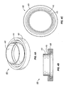
- Figs. 4A, 4B, and 4C illustrate one embodiment of a ring magnet or magnetic array collar 400, which can be used to implement the models 300 and 350.
- the collar 400 includes a plurality of magnets 405, a magnet/bushing interface 410, and a bushing 415.
- Two magnetic array collars 400 can be positioned opposing each other, with the poles of the magnets 405 generally aligned to create relative angular displacement sensor (such as that shown in the models 300-315).
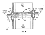
- Fig. 5 illustrates an absolute position and torque sensing apparatus 500 that includes a position magnetic array 505, a dual function torque/position magnetic array 510, a second torque sensing magnetic array 515, a first field direction sensor 520 (that senses magnetic field direction used to determine absolute position), and a second field direction sensor 525 (that senses magnetic field direction used to determine torque).
- the array 505 and the array 510 are positioned on an input shaft 530 (or, more broadly a rotational platform).
- the array 515 is positioned on an output shaft 535 (also a rotational platform).
- a torsional coupling is used to couple the input shaft 530 and output shaft 535 such that a torsional load will cause an angular deflection to occur between the two shafts 530 and 535.
- the position and torque sensing apparatus 500 also includes a position processing module 537 and a torque processing module 539.
- each of the magnetic arrays 505, 510, and 515 are positioned generally proximate to each other.
- the position magnetic array 505 is positioned at one end of the three array combination, and includes one more pole pair than the torque/position magnetic array 510 and the torque array 515.
- the first field sensor 520 measures the magnetic field direction angle between the position magnetic array 505 and the first torque/position magnetic array 510, the absolute value of which changes proportionally with the angular displacement of the input shaft 530.
- the position processing module 537 includes a housing 540 to protect the magnetic field sensor 520 from the environment (e.g., dust, moisture, etc.).
- the position processing module 537 also includes a connector 545, which may include pins or other electrical connections to support the transmission of power and data.
- the module 537 includes a printed circuit board 550, which may hold the first field sensor 520, a signal conditioning ASIC (not shown), and other components, such as an EMI filter (not shown).
- the torque/position magnetic arrays 510 and torque magnetic array 515 include an identical number of poles.
- the second field sensor 525 measures the changing magnetic field direction between the poles of the torque/position magnetic arrays 510 and torque magnetic array 515 when the input shaft 530 angular position moves with respect the output shaft 535.
- the second field sensor 525 can be arranged within the torque processing module 539, which, similar to the position processing module 537 described above, includes a housing 555, a connector 560, and a printed circuit board assembly 565.
- An embodiment combining the absolute angular position sensor 100 and the relative angular displacement sensor 200 (such as the position and torque sensing apparatus 500) has the potential to simplify installation and lower the overall electric power steering system cost.
- Other applications for the position absolute angular position sensor 100 and the relative angular displacement sensor 200 exist.
- embodiments of an absolute angular position sensor may be used for determining motor position in precision brushless DC motor commutation systems.
- Advanced engine controls may use a relative angular displacement sensor to monitor torque in support of electronic engine control algorithms.
- Absolute and relative position sensors may also be used in 1) seat belt retractors for advanced safety restraints and belt tension control; and 2) drive-by-wire systems to sense pedal and throttle positions for electronic engine control.
- Other applications and embodiments of the invention may include clutches for drive wheels and transmissions.
- Industrial equipment that requires position control and torque sensing may also find applications for position and torque sensing systems implemented with embodiments of the invention.
Description
- The present invention relates to field sensors and, in particular, to magnetic sensors for determining position and torque.
- Magnetic sensing for determining a position or speed of a moving component is known and is used in applications such as power steering, braking, and motor control systems. Motor position sensing and steering wheel position sensing are similar in at least one way: access to the end of the moving shaft is generally limited or non-existent because the end of the shaft is connected to operating components. Thus, sensing is usually performed at the side of the shaft. For instance, a target magnet positioned on a shaft can be detected with a magnetic sensing element or sensor positioned concentric to the longitudinal axis of the shaft. In one application, the sensor may include components configured to count the number of times the shaft rotates. In a different application, the position of the shaft may be determined using several target magnets.
- Resolvers and encoders are often used to process the raw information generated by the magnetic components. Resolvers provide an absolute output signal and encoders provide a relative output signal. The absolute nature of the signal from a resolver is desirable, but resolvers are often complex and expensive. Encoders are, in general, simpler and cheaper than resolvers, but can be inaccurate. In some cases, error detection hardware is used with encoders, but this adds complexity.
-
US 2003/0145663 A1 discloses a sensor including three multi-pole wheels and three sensor elements. Each sensor element is positioned opposite from one of the multi-pole wheels. -
WO 89/05540 A1 -
WO 02/16879 A1 -
US 2002/0118011 A1 discloses several low carbon ferrous plates. A magnet 14 is located at each end of a ferrous plate. - Accordingly, improved magnetic and field sensors are desirable. For example, current automotive steering systems appear to lack a torsion detector and position detector that directly measures the positon of the wheel and the torque to the wheel simultaneously.
- In one embodiment the invention provides for a relative angular displacement sensor. The sensor also includes a magnetic field direction sensor element, such as an anisotropic magnetoresistive ("AMR") sensor, positioned above and between the first array and the second array.
- The sensor may be used in different relative angular displacement sensing applications. For example the first array may be positioned on an input shaft of a steering torque sensing assembly and the second array may be positioned on an output shaft. The field sensor may be located to sense the relative angular position between the two arrays and ultimately the relative angular position of one shaft with respect to the other.
- In another embodiment, the invention provides for an absolute position sensor. The absolute position sensor includes a second array of N magnetic pole pairs, where N is a positive number. The sensor also includes a first array of M magnetic pole pairs, where M is a positive number equal to N-1
array N+ 1. The second array is arranged substantially in parallel to the first array, and mechanically coupled to the first array. The sensor also includes a magnetic field direction sensor element, such as an AMR sensor, positioned above and between the first array and the second array. - The sensor may be used in different absolute position sensing applications. For example, the mechanically coupled first and second arrays may be positioned on a steering shaft with a field sensor located between the two arrays to sense the absolute rotational position of the steering shaft.
- In another embodiment, the invention provides an absolute angular position and relative angular displacement sensor. The absolute angular position and relative angular displacement sensor includes a first array of magnetic pole pairs, a second array of magnetic pole pairs and a third array of magnetic pole pairs, arranged substantially in parallel to, and mechanically coupled to the second array. A first field sensor is positioned above and between the first array and the second array, and a second field sensor is positioned above and between the second and third array. The first and second field sensors may be an AMR sensor or an array of AMR sensors.
- Other aspects of embodiments of the invention will become apparent by consideration of the detailed description and accompanying drawings.
-
-
Fig. 1A illustrates an absolute linear position sensing system. -
Fig. 1B illustrates an absolute angular position sensing system. -
Fig. 2A illustrates a relative angular displacement sensing system for measuring torque. -
Fig. 2B illustrates another embodiment of the relative angular displacement sensing system for measuring torque as shown inFig. 2A . -
Fig. 3A illustrates a computer model of a relative angular displacement sensor. -
Fig. 3B illustrates another computer model of the relative angular displacement sensor as shown inFig. 3A . -
Fig. 3C illustrates yet another computer model of the relative angular displacement sensor as shown inFig. 3A . -
Fig. 3D illustrates still another computer model of the relative angular displacement sensor as shown inFig. 3A . -
Fig. 4A illustrates a ring magnet. -
Fig. 4B illustrates a cross-sectional view of the ring magnet shown inFig. 4A . -
Fig. 4C illustrates a top view of the ring magnet shown inFig. 4A . -
Fig. 5 illustrates a position and torque sensing system. - Before embodiments of the invention are explained in detail, it is to be understood that the embodiments described are not limited to the details of construction and the arrangement of components set forth in the following description or illustrated in the following drawings, which are provided as examples. Embodiments can take other forms and be used in other applications.
-
Fig. 1A illustrates an exemplary absolute linearposition sensing system 100. The absolute linearposition sensing system 100 includes a firstmagnetic array 105, a secondmagnetic array 110, and a magnetic field orfield sensor 115. The field sensor may be a type of magnetoresistive sensor such as an AMR sensor. An array of AMR sensors can also be used. The firstmagnetic array 105 and secondmagnetic array 110 are mechanically coupled to each other to move as a single unit. Thefield sensor 115 is positioned between themagnetic arrays arrays position sensing system 100 can also include processing components (such as those shown inFig. 5 ), which are capable of receiving and processing signals from thefield sensor 115. - The first
magnetic array 105 includes "N" magnetic pole pairs. Each pole pair includes anorth pole 120 and asouth pole 125. The secondmagnetic array 110 includes "M" magnetic pole pairs. M is a number that is different from N, which can be equal to N+1 or N-1. In the embodiment shown, M is equal to N+1. The magnetic pole pairs of the secondmagnetic array 110 also include north and south poles, designated withreference numerals magnetic array 110 to a corresponding and opposite magnetic pole in the firstmagnetic array 105, the difference in the number of poles (e.g., either N+1 or N-1) in thesecond array 110 creates a misalignment between the other poles. This pole misalignment creates a differential magnetic field direction 130N which varies proportionally with position along the face of the magnetic array. In other words, the field between the arrays changes orientation in respect to position. The differential magnetic field direction 130N between each of the opposite poles of themagnetic arrays - In the embodiment shown, the
magnetic arrays field sensor 115. In most instances, the magnetic field strength of each magnet in thearrays - The
field sensor 115 is positioned between and spaced from thearrays field sensor 115 is positioned above the arrays a certain distance. In one embodiment, this distance is 1.7 mm. However, it is possible to locate thefield sensor 115 at different distances and in a position that is adjacent to the arrays, but not above them. The magnetic field sensor measures the angle of the magnetic field direction 130N. As the first and secondmagnetic arrays field sensor 115, the magnetic field 130N alternates between 0 and 0 + 180 with each pole pair. In addition, the field angle Ø shifts linearly from a minimum level of -β at a null point, to a maximum of +β when the null point is reached at an opposing end of themagnetic arrays Fig. 1A represents the approximate magnetic fields between the twomagnetic arrays - As noted above, the
field sensor 115 can take the form of an AMR sensor or array of AMR sensors. Some AMR sensors can not detect the difference between a field angle of Ø and that of Ø + 180. As a result, when such AMR sensors are used, the output of themagnetic field sensor 115 is not affected by the alternating polarity changes, or the changing boundary conditions at the north and south pole interfaces. However, an AMR sensor can be configured to detect the absolute field angle difference described above. For example, in one embodiment, thefield sensor 115 is a four-element sin/cos AMR sensor. The four elements provide a device that bridges the length of a single magnetic pole on themagnetic array magnetic arrays -
Fig. 1B illustrates an exemplary absolute angularposition sensing system 150. The absolute angularposition sensing system 150 includes a firstmagnetic array 155, a secondmagnetic array 160, and a magnetic field orfield sensor 165, such as an AMR sensor or array of AMR sensors. The firstmagnetic array 155, and secondmagnetic array 160 are mechanically coupled to each other moving as a single unit. Thefield sensor 165 is positioned between themagnetic arrays magnetic field 170 created between the twoarrays position sensing system 150 can also include processing components (such as those shown inFig. 5 ), which are capable of receiving and processing signals from thefield sensor 165. - In the absolute angular displacement sensing embodiment as depicted in
Fig. 1B , the components function to provide a magnetic field direction that changes in proportion to rotary position. In other regards, the function of the magnetic arrays and field angle sensor are substantially identical to that more fully described in the absolute linear position sensing embodiment,Fig. 1A . -
Figs. 2A and 2B illustrate a relative angulardisplacement sensing system 200, shown assembled as part of a larger device such as steering torque sensing system. The relative angulardisplacement sensing system 200 includes a firstmagnetic array 205, a secondmagnetic array 210, and a magnetic field orfield sensor 215. Aninput shaft 220 and anoutput shaft 225 are separated by atorque coupling 230. Thetorque coupling 230 is designed to flex when a torque is applied to either shaft, resulting in an angular displacement between theinput shaft 220 andoutput shaft 225 in proportion to the applied torsional load. - The first
magnetic array 205 includes 12 magnetic pole pairs, which alternate between anorth pole 235 and asouth pole 240. However, in other embodiments, more magnetic pole pairs can be used. In the embodiment shown, the firstmagnetic array 205 is attached or coupled to theinput shaft 220. The secondmagnetic array 210 also includes 12 magnetic poles pairs, which alternate between anorth pole 235 and asouth pole 240. The secondmagnetic array 210 is attached or coupled to theoutput shaft 225, and is generally aligned with the firstmagnetic array 205, as shown inFig. 2A . Thefield sensor 215, similar to thefield sensor 115 shown inFigs. 1A , is positioned between the first and secondmagnetic field arrays output shafts - When the
input shaft 220 and theoutput shaft 225 are in a static relationship (e.g., no torque is being applied to the input shaft 220), as shown inFig. 2A , the poles of themagnetic arrays magnetic fields 245 between thearrays magnetic field lines 245 are generally parallel to thearrays 205 and 210). However, when a torque is applied, as shown inFig. 2B , theinput shaft 220 and theoutput shaft 225 become misaligned about thetorque coupling 230, causing themagnetic arrays magnetic fields 245 also change. - The magnetic field direction changes described above can be measured using the
field sensor 215. For example, as long as theshafts magnetic arrays magnetic arrays input shaft 220 rotates, the field angle is shifted (e.g., alternates between Ø and Ø + 180). That field angle is measured using thefield sensor 215 to provide an indication of the relative angular displacement of the input shaft and the output shaft which is proportional to the amount of torque applied. Measuring relative position in this way can be useful for a variety of applications. For example, the torque created at the steering wheel shaft during maneuvers can be inferred by measuring the relative position change between two torsionally coupled shaft segments. In another embodiment, the torque created within an electric motor or transmission can be inferred in a similar manner. In such embodiments, thefield sensor 215 is used to measure the direction change in themagnetic field 245, providing a direct measurement of the angular displacement of the two shafts which is proportional to the amount of torque that is being applied. In contrast to the position sensing embodiment, the angle orientation is the same between all of the corresponding poles between themagnetic arrays shafts - The maximum measurement range in the relative angular displacement embodiment is inversely dependent on the quantity of pole pairs within the magnetic array. The greater the number of pole pairs the smaller the full scale measurement range and visa versa. This relationship can be defined as follows:
- Maximum Angular Displacement = +/- 360/(# of Magnetic Pole Pairs)
- In
Figs. 2A and 2B , themagnetic arrays - Small differences in spacing between the opposing pole pairs of the
magnetic arrays magnetic field 245 between the corresponding poles varies across thefield sensor 215. This noise can increase as the difference between opposing pole pair spacing increases. For example, if the maximum spacing error between opposing pole pairs is equivalent to 2 electrical degrees, and there are 24 pole pairs, the noise error on the torque signal is approximately 2/24 or +/- 0.083 degrees. However, this error can be reduced by increasing the number of pole pairs in each of the magnetic arrays. In some embodiments, there are 24 pole pairs, but the number of pole pairs may range between about 12 and 36 for typical applications. -
Figs. 3A-3D illustratecomputer models input shaft 320 that is separated from anoutput shaft 325 by anelastic torque coupling 330. Theinput shaft 320 andoutput shaft 325 each include amagnetic array magnetic arrays AMR sensor array 345 that bridges across the dimension of one pole is positioned above themagnetic arrays - As shown in
Fig. 3A , when themagnetic arrays magnetic field vectors 350 in the plane of theAMR sensor array 345 are generally perpendicular along the length of the array. Thecomputer model 300 was generated using twelve pole pairs for each of themagnetic arrays model 300, the poles of themagnetic arrays Fig. 3B ) are not aligned and are displaced with respect to each other. This type of angular displacement can occur, for example, when a torque is applied to theinput shaft 320. The angular displacement of themagnetic arrays magnetic field vectors 350. As can be seen inFig. 3B the magnetic field vectors in the plane of AMR sensor array change across the face of the array. The average of this change is proportional to the angular displacement ofmagnetic arrays magnetic arrays Figs. 3C and 3D , a 5 degree angular displacement results in a 17.5 degree average magnetic field angle, and a 7.5 degree angular displacement results in a 30.5 degree average magnetic field angle, respectively. In other embodiments, the relationship between angular displacement and average magnetic field angle can be different. - The models 300-315 generally illustrate that the displacement of two multi-pole magnets in proximity to each other creates a differential magnetic field vector direction that changes in relationship to the angular displacement of the magnetic arrays with respect to each other. Additionally, the average of the absolute value of the differential magnetic field direction in the plane parallel to and along the axis of motion of the
shafts shafts -
Figs. 4A, 4B, and 4C illustrate one embodiment of a ring magnet ormagnetic array collar 400, which can be used to implement themodels collar 400 includes a plurality ofmagnets 405, a magnet/bushing interface 410, and abushing 415. Twomagnetic array collars 400 can be positioned opposing each other, with the poles of themagnets 405 generally aligned to create relative angular displacement sensor (such as that shown in the models 300-315). - The absolute angular position sensors and the relative angular displacement sensors described herein utilize the differential magnetic fields that result from positioning two multi-pole magnets in a close proximity to one another. Thus, in one embodiment, the absolute
angular position sensor 100 and relativeangular displacement sensor 200 can be combined into a single sensing module or apparatus.Fig. 5 illustrates an absolute position andtorque sensing apparatus 500 that includes a positionmagnetic array 505, a dual function torque/positionmagnetic array 510, a second torque sensingmagnetic array 515, a first field direction sensor 520 (that senses magnetic field direction used to determine absolute position), and a second field direction sensor 525 (that senses magnetic field direction used to determine torque). Thearray 505 and thearray 510 are positioned on an input shaft 530 (or, more broadly a rotational platform). Thearray 515 is positioned on an output shaft 535 (also a rotational platform). A torsional coupling, not shown, is used to couple theinput shaft 530 andoutput shaft 535 such that a torsional load will cause an angular deflection to occur between the twoshafts torque sensing apparatus 500 also includes aposition processing module 537 and atorque processing module 539. - As shown in
Fig. 5 , each of themagnetic arrays magnetic array 505 is positioned at one end of the three array combination, and includes one more pole pair than the torque/positionmagnetic array 510 and thetorque array 515. Thefirst field sensor 520 measures the magnetic field direction angle between the positionmagnetic array 505 and the first torque/positionmagnetic array 510, the absolute value of which changes proportionally with the angular displacement of theinput shaft 530. - Information sensed by the
first field sensor 520 is provided to theposition processing module 537. Theposition processing module 537 includes ahousing 540 to protect themagnetic field sensor 520 from the environment (e.g., dust, moisture, etc.). Theposition processing module 537 also includes aconnector 545, which may include pins or other electrical connections to support the transmission of power and data. In some embodiments, themodule 537 includes a printedcircuit board 550, which may hold thefirst field sensor 520, a signal conditioning ASIC (not shown), and other components, such as an EMI filter (not shown). - The torque/position
magnetic arrays 510 and torquemagnetic array 515 include an identical number of poles. Thesecond field sensor 525 measures the changing magnetic field direction between the poles of the torque/positionmagnetic arrays 510 and torquemagnetic array 515 when theinput shaft 530 angular position moves with respect theoutput shaft 535. Thesecond field sensor 525 can be arranged within thetorque processing module 539, which, similar to theposition processing module 537 described above, includes ahousing 555, aconnector 560, and a printedcircuit board assembly 565. - An embodiment combining the absolute
angular position sensor 100 and the relative angular displacement sensor 200 (such as the position and torque sensing apparatus 500) has the potential to simplify installation and lower the overall electric power steering system cost. Other applications for the position absoluteangular position sensor 100 and the relativeangular displacement sensor 200 exist. For example, embodiments of an absolute angular position sensor may be used for determining motor position in precision brushless DC motor commutation systems. Advanced engine controls may use a relative angular displacement sensor to monitor torque in support of electronic engine control algorithms. Absolute and relative position sensors may also be used in 1) seat belt retractors for advanced safety restraints and belt tension control; and 2) drive-by-wire systems to sense pedal and throttle positions for electronic engine control. Other applications and embodiments of the invention may include clutches for drive wheels and transmissions. Industrial equipment that requires position control and torque sensing may also find applications for position and torque sensing systems implemented with embodiments of the invention. - Various features and aspects of embodiments the invention are set forth in the following claims.
Claims (2)
- A sensor (500) comprising: a rotatable first array (505) of M magnetic pole pairs, where M is a positive number; a rotatable second array (510) of N magnetic pole pairs, arranged substantially in parallel to and mechanically coupled to the first array (505), where N is a positive number different than M, to form a first magnetic field between the first and second arrays (505, 510) that changes orientation in respect to position; a first field sensor (520) positioned adjacent with respect to a radial extent of the first array (505) and the second array (510) and between the first array (505) and the second array (510) with respect to an axial direction of the sensor (500); and a rotatable third array (515) of N magnetic pole pairs and a second field sensor (525), wherein the third array (515) is located adjacent to the second array (510) to form a second magnetic field in between the second and third arrays (510, 515) that changes orientation with respect to a displacement between the second and third arrays (510, 515) and wherein the second field sensor (525) is located adjacent with respect to a radial extent of the second array (510) and the third array (515) and between the second array and the third array (S10, 515) with respect to an axial direction of the sensor (500).
- A method of sensing changes in a magnetic field, the method comprising: providing a first array (505) of M magnetic pole pairs, where M is a positive number; arranging a second array (510) of N magnetic pole pairs, substantially in parallel to and to move in concert with the first array (505), where N is a positive number different than M; arranging a first field sensor (520) between the first and second arrays (505, 510); sensing changes in orientation of a magnetic field between the first and second arrays (505, 510) as the first and second arrays (505, 510) and the first field sensor (520) move relative to one another; and providing a third array (515) of N magnetic pole pairs substantially in parallel to and to move independently of the first and second arrays (505, 510); arranging a second field sensor (525) between the second and third arrays (510, 515); and sensing an angular orientation of a magnetic field formed between the second and third arrays (510, 515).
Applications Claiming Priority (2)
| Application Number | Priority Date | Filing Date | Title |
|---|---|---|---|
| US11/299,156 US7339370B2 (en) | 2005-12-09 | 2005-12-09 | Position and torque sensor |
| PCT/US2006/003993 WO2007067196A1 (en) | 2005-12-09 | 2006-02-03 | Position and torque sensor |
Publications (3)
| Publication Number | Publication Date |
|---|---|
| EP1969305A1 EP1969305A1 (en) | 2008-09-17 |
| EP1969305A4 EP1969305A4 (en) | 2011-01-26 |
| EP1969305B1 true EP1969305B1 (en) | 2015-08-26 |
Family
ID=38123198
Family Applications (1)
| Application Number | Title | Priority Date | Filing Date |
|---|---|---|---|
| EP06734368.1A Active EP1969305B1 (en) | 2005-12-09 | 2006-02-03 | Position and torque sensor |
Country Status (4)
| Country | Link |
|---|---|
| US (1) | US7339370B2 (en) |
| EP (1) | EP1969305B1 (en) |
| DE (1) | DE06734368T1 (en) |
| WO (1) | WO2007067196A1 (en) |
Families Citing this family (24)
| Publication number | Priority date | Publication date | Assignee | Title |
|---|---|---|---|---|
| DE102007025000B3 (en) * | 2007-05-30 | 2008-12-11 | Infineon Technologies Ag | Magnetic field sensor for monitoring wheel movement in anti-skid system of automobiles, has magnetic field sensor arrangement and magnet body |
| US10852367B2 (en) | 2007-05-30 | 2020-12-01 | Infineon Technologies Ag | Magnetic-field sensor with a back-bias magnet |
| US10338158B2 (en) | 2007-05-30 | 2019-07-02 | Infineon Technologies Ag | Bias magnetic field sensor |
| CN101855811B (en) | 2007-06-27 | 2013-11-20 | 布鲁克斯自动化公司 | Motor stator with lift capability and reduced cogging characteristics |
| US8823294B2 (en) | 2007-06-27 | 2014-09-02 | Brooks Automation, Inc. | Commutation of an electromagnetic propulsion and guidance system |
| US9752615B2 (en) | 2007-06-27 | 2017-09-05 | Brooks Automation, Inc. | Reduced-complexity self-bearing brushless DC motor |
| WO2009003193A1 (en) * | 2007-06-27 | 2008-12-31 | Brooks Automation, Inc. | Position feedback for self bearing motor |
| JP5663304B2 (en) | 2007-06-27 | 2015-02-04 | ブルックス オートメーション インコーポレイテッド | Multi-dimensional position sensor |
| US8283813B2 (en) * | 2007-06-27 | 2012-10-09 | Brooks Automation, Inc. | Robot drive with magnetic spindle bearings |
| US20100218619A1 (en) * | 2007-10-22 | 2010-09-02 | The Timken Company | Drive torque sensing wheel end |
| US8085036B2 (en) * | 2009-01-14 | 2011-12-27 | Infineon Technologies Ag | Sensor including two code rings and a magnetic field sensor between the code rings |
| JP5193110B2 (en) * | 2009-03-31 | 2013-05-08 | 日立電線株式会社 | Torque index sensor |
| KR101864903B1 (en) | 2010-05-14 | 2018-07-04 | 티알더블유 오토모티브 유.에스.엘엘씨 | Torque sensor assembly and method for producing same |
| JP5480758B2 (en) | 2010-09-13 | 2014-04-23 | 日立金属株式会社 | Torque index sensor |
| DE102011002563A1 (en) * | 2010-12-20 | 2012-06-21 | Robert Bosch Gmbh | sensor arrangement |
| US9103696B2 (en) * | 2011-08-15 | 2015-08-11 | Honeywell International Inc. | Extended range position sensor system |
| US9513202B2 (en) * | 2012-08-14 | 2016-12-06 | BEL Legacy Corporation | Viscometer |
| GB2532789B (en) * | 2014-11-28 | 2017-02-15 | Imp Innovations Ltd | Absolute rotary encoder |
| GB2552478B (en) * | 2016-07-22 | 2021-04-28 | Cmr Surgical Ltd | Magnetic position sensor |
| GB2552385B (en) | 2016-07-22 | 2021-09-15 | Cmr Surgical Ltd | Calibrating position sensor readings |
| GB2552386B (en) | 2016-07-22 | 2022-06-08 | Cmr Surgical Ltd | Magnetic position sensor mounting arrangement |
| DE102016221517A1 (en) * | 2016-11-03 | 2018-05-03 | Schaeffler Technologies AG & Co. KG | Sensor arrangement with an AMR sensor and rotary bearing with such a sensor arrangement |
| US10605217B2 (en) * | 2017-03-07 | 2020-03-31 | GM Global Technology Operations LLC | Vehicle engine starter control systems and methods |
| JP2020101439A (en) * | 2018-12-21 | 2020-07-02 | 株式会社竹中製作所 | Gas meter and manufacturing method thereof |
Family Cites Families (21)
| Publication number | Priority date | Publication date | Assignee | Title |
|---|---|---|---|---|
| JPS6276607U (en) * | 1985-10-31 | 1987-05-16 | ||
| GB2188430B (en) * | 1986-03-19 | 1990-01-17 | Honda Motor Co Ltd | Angle-of-rotation sensor |
| SE459833B (en) * | 1987-12-09 | 1989-08-07 | Astra Tech Ab | ROTATING ELECTRIC MACHINE |
| DE19543564A1 (en) * | 1994-11-22 | 1996-05-23 | Bosch Gmbh Robert | Non-contact rotary angle determn. appts for rotating element |
| EP0880013B1 (en) * | 1997-05-21 | 2003-04-09 | Robert Bosch Gmbh | Operating method for a positioning sensor |
| DE19739823A1 (en) * | 1997-09-11 | 1999-03-18 | Bosch Gmbh Robert | Method and device for measuring the angle of a first rotatable body |
| DE19747638C1 (en) * | 1997-10-29 | 1999-07-01 | Zahnradfabrik Friedrichshafen | Electrically assisted power steering for motor vehicles |
| DE19747753C1 (en) * | 1997-10-29 | 1999-05-12 | Ruf Electronics Gmbh | Method for determining the phase angle in position encoders with sinusoidal output signals |
| DE19839446A1 (en) * | 1998-08-29 | 2000-03-02 | Bosch Gmbh Robert | Arrangement for detecting the angle of rotation of a rotatable element |
| DE19839646A1 (en) * | 1998-08-31 | 2000-03-09 | Jomed Implantate Gmbh | Stent |
| DE19849554C1 (en) * | 1998-10-27 | 2000-03-02 | Ruf Electronics Gmbh | Method to determine absolute position with displacement and angle transducers; involves using two mechanically coupled sensors with output signals with numbers of periods different by one |
| DE19855960A1 (en) * | 1998-12-04 | 2000-06-08 | Bosch Gmbh Robert | Device and method for measuring the angular position of a rotatable body |
| US6935193B2 (en) * | 1999-12-06 | 2005-08-30 | Robert Bosch Gmbh | Device for measuring the angle and/or the angular velocity of a rotatable body and/or the torque acting upon said body |
| DE10041092A1 (en) * | 2000-08-22 | 2002-03-07 | Bosch Gmbh Robert | Method for correcting a phase angle when scanning a code track |
| US6515471B1 (en) * | 2000-10-11 | 2003-02-04 | The Torrington Company | Absolute position hall string sensor |
| US6753680B2 (en) * | 2000-11-29 | 2004-06-22 | Ronald J. Wolf | Position sensor |
| JP2003114103A (en) * | 2001-10-02 | 2003-04-18 | Koyo Seiko Co Ltd | Angle-of-rotation detector, torque detector and steering gear |
| JP4209155B2 (en) * | 2002-03-05 | 2009-01-14 | アルプス電気株式会社 | Rotation angle detector |
| EP1471332A1 (en) * | 2003-04-17 | 2004-10-27 | Dialog Semiconductor GmbH | Digital interface for an angular sensor |
| JP4470577B2 (en) * | 2004-05-14 | 2010-06-02 | 株式会社デンソー | Rotation angle detector |
| US7112962B2 (en) * | 2004-11-18 | 2006-09-26 | Honeywell International Inc. | Angular position detection utilizing a plurality of rotary configured magnetic sensors |
-
2005
- 2005-12-09 US US11/299,156 patent/US7339370B2/en active Active
-
2006
- 2006-02-03 EP EP06734368.1A patent/EP1969305B1/en active Active
- 2006-02-03 DE DE06734368T patent/DE06734368T1/en active Pending
- 2006-02-03 WO PCT/US2006/003993 patent/WO2007067196A1/en active Application Filing
Also Published As
| Publication number | Publication date |
|---|---|
| WO2007067196A1 (en) | 2007-06-14 |
| DE06734368T1 (en) | 2008-12-24 |
| US20070132447A1 (en) | 2007-06-14 |
| EP1969305A1 (en) | 2008-09-17 |
| US7339370B2 (en) | 2008-03-04 |
| EP1969305A4 (en) | 2011-01-26 |
Similar Documents
| Publication | Publication Date | Title |
|---|---|---|
| EP1969305B1 (en) | Position and torque sensor | |
| US4724710A (en) | Electromagnetic torque sensor for a rotary shaft | |
| US6880411B2 (en) | Torque sensor and electric power steering system having same | |
| US4984474A (en) | Torque sensor | |
| US7307416B2 (en) | Position sensor and assembly | |
| US4784002A (en) | Torque sensor | |
| US8800388B2 (en) | Torque sensor apparatus | |
| JP4718081B2 (en) | Sensor device for detecting rotation angle and / or torque | |
| EP1451591B1 (en) | Magnetoresistive speed and direction sensing method and apparatus | |
| WO2005108943A1 (en) | Torque detection device | |
| JP2000028312A (en) | Low profile non-contacting position sensor | |
| US20050007104A1 (en) | Sensor assembly for sensing angular position | |
| US20160041007A1 (en) | Hall Sensor Insensitive to External Magnetic Fields | |
| KR20140015323A (en) | Rotation angle detection device | |
| CA2373381A1 (en) | Position encoder utilizing fluxgate sensors | |
| US20210302246A1 (en) | Torque sensor device, method for determining a torque, stator and stator arrangement | |
| JP4250418B2 (en) | Instrumented bearings for steering wheels | |
| KR20140069005A (en) | Combined steering torque-steering angle sensor | |
| JP2008151628A (en) | Rotation sensor | |
| EP3612801A1 (en) | Methods and systems for measuring parameters of rotating shafts and couplings | |
| US20220011085A1 (en) | Inductive position sensor comprising at least one transmit coil, an absolute position receive coil pair, a high-resolution position receive coil pair and a conductive moving target | |
| US7391206B2 (en) | Magnetic detection circuit and encoder | |
| KR20130136765A (en) | Torque sensor | |
| JP6959133B2 (en) | Torque sensor | |
| WO2007041465A1 (en) | Redundant angle sensor |
Legal Events
| Date | Code | Title | Description |
|---|---|---|---|
| PUAI | Public reference made under article 153(3) epc to a published international application that has entered the european phase |
Free format text: ORIGINAL CODE: 0009012 |
|
| 17P | Request for examination filed |
Effective date: 20080626 |
|
| AK | Designated contracting states |
Kind code of ref document: A1 Designated state(s): DE |
|
| DET | De: translation of patent claims | ||
| RBV | Designated contracting states (corrected) |
Designated state(s): DE |
|
| A4 | Supplementary search report drawn up and despatched |
Effective date: 20101228 |
|
| DAX | Request for extension of the european patent (deleted) | ||
| 17Q | First examination report despatched |
Effective date: 20131011 |
|
| REG | Reference to a national code |
Ref country code: DE Ref legal event code: R079 Ref document number: 602006046431 Country of ref document: DE Free format text: PREVIOUS MAIN CLASS: G01B0007140000 Ipc: G01D0005245000 |
|
| RIC1 | Information provided on ipc code assigned before grant |
Ipc: G01L 3/10 20060101ALI20150213BHEP Ipc: G01D 5/245 20060101AFI20150213BHEP |
|
| GRAP | Despatch of communication of intention to grant a patent |
Free format text: ORIGINAL CODE: EPIDOSNIGR1 |
|
| INTG | Intention to grant announced |
Effective date: 20150327 |
|
| GRAS | Grant fee paid |
Free format text: ORIGINAL CODE: EPIDOSNIGR3 |
|
| GRAA | (expected) grant |
Free format text: ORIGINAL CODE: 0009210 |
|
| AK | Designated contracting states |
Kind code of ref document: B1 Designated state(s): DE |
|
| REG | Reference to a national code |
Ref country code: DE Ref legal event code: R096 Ref document number: 602006046431 Country of ref document: DE |
|
| REG | Reference to a national code |
Ref country code: DE Ref legal event code: R097 Ref document number: 602006046431 Country of ref document: DE |
|
| PLBE | No opposition filed within time limit |
Free format text: ORIGINAL CODE: 0009261 |
|
| STAA | Information on the status of an ep patent application or granted ep patent |
Free format text: STATUS: NO OPPOSITION FILED WITHIN TIME LIMIT |
|
| 26N | No opposition filed |
Effective date: 20160530 |
|
| PGFP | Annual fee paid to national office [announced via postgrant information from national office to epo] |
Ref country code: DE Payment date: 20221230 Year of fee payment: 18 |
|
| P01 | Opt-out of the competence of the unified patent court (upc) registered |
Effective date: 20230514 |