EP1968846B1 - Fifth wheel slide interlock - Google Patents
Fifth wheel slide interlock Download PDFInfo
- Publication number
- EP1968846B1 EP1968846B1 EP05855635A EP05855635A EP1968846B1 EP 1968846 B1 EP1968846 B1 EP 1968846B1 EP 05855635 A EP05855635 A EP 05855635A EP 05855635 A EP05855635 A EP 05855635A EP 1968846 B1 EP1968846 B1 EP 1968846B1
- Authority
- EP
- European Patent Office
- Prior art keywords
- wheel
- speed
- switch
- vehicle
- threshold
- Prior art date
- Legal status (The legal status is an assumption and is not a legal conclusion. Google has not performed a legal analysis and makes no representation as to the accuracy of the status listed.)
- Expired - Lifetime
Links
Images

Classifications
-
- B—PERFORMING OPERATIONS; TRANSPORTING
- B62—LAND VEHICLES FOR TRAVELLING OTHERWISE THAN ON RAILS
- B62D—MOTOR VEHICLES; TRAILERS
- B62D53/00—Tractor-trailer combinations; Road trains
- B62D53/04—Tractor-trailer combinations; Road trains comprising a vehicle carrying an essential part of the other vehicle's load by having supporting means for the front or rear part of the other vehicle
- B62D53/08—Fifth wheel traction couplings
- B62D53/0807—Fifth wheel traction couplings adjustable coupling saddles mounted on sub-frames; Mounting plates therefor
- B62D53/0814—Fifth wheel traction couplings adjustable coupling saddles mounted on sub-frames; Mounting plates therefor with adjustment of the clearance between the tractor or the trailer
Definitions
- This invention relates to systems and methods of controlling a vehicle, especially a heavy vehicle such as a highway truck or a tractor, in particular by controlling the vehicle's fifth wheel.
- Over-the-highway trucks and tractor-trailer combinations come in many different sizes and configurations, and the relative geometry of the tractor and trailer in a load-carrying vehicle such as a class-8 tractor-trailer combination can vary widely.
- the distribution of a tractor-trailer's weight on its axles can vary based on, among other factors, the position of a "fifth wheel” with respect to the cab of the tractor.
- a "fifth wheel” is generally a wheel or portion of a wheel placed horizontally over the rear axle or axles of a tractor or truck that is a coupling for a trailer.
- FIG. 1 is a side view of a typical tractor 100 having a cab 102, front wheels and axle 104, a pair of rear wheels and axles 106, and a fifth wheel 108.
- Some tractors have sliding fifth wheels, which can be used to manage vehicle weight distribution by moving the trailer closer to or farther from the tractor.
- JP 2003 089365 A to Hino Motors LTD describes a tractor comprising an enlarged adjustable length of the fifth wheel to make it possible to adjust the position of the fifth wheel so that the coupling point suits different kinds of trailer. The load distribution of the axles is changed properly and the safety on employment is improved.
- U.S. Patent No. 4,429,892 to Frampton et al. describes a device for attachment to a tractor for selectively moving the fifth wheel assembly of the tractor. The device has two drive members that can be extended or contracted from the cab of the tractor to slide the fifth wheel back and forth.
- U.S. Patent No. 6,384,716 to Eckelberry describes a trailer slider positioning alarm.
- the slider (fifth wheel) is locked in place with a set of pins.
- a speed sensor detects a speed of the unit and a pin position sensor detects whether any of the pins are unlocked.
- An alarm sends an alert signal in response to the speed sensor's detection of a predetermined speed and the pin position sensor's detection of at least one unlocked pin.
- Some sliding fifth wheels are actuated by pneumatic pressure that is controlled from the dash in the cab of the tractor. Actuating a switch on the dash locks and unlocks the position of the fifth wheel.
- the fifth wheel slide lock may be activated by an electrically controlled air solenoid or similar device.
- a vehicle speed interlock can be used to prevent the fifth wheel slide from being unlocked while the vehicle is moving.
- a system for controlling a position of a fifth wheel for a vehicle includes a sensor configured to provide an indication of a speed of the vehicle; a switch actuatable to unlock the position of the fifth wheel; and a processor configured to receive the indication of the speed of the vehicle and an indication of a state of the switch. If the vehicle's speed is below a threshold and the switch is actuated to unlock the fifth wheel, the processor generates a control signal that enables the fifth wheel to be unlocked; and if the speed is above the threshold and the switch is actuated to unlock the fifth wheel, the processor generates a control signal that prevents the fifth wheel from being unlocked.
- a method of controlling a position of a fifth wheel on a vehicle includes the steps of determining a state of a switch that is actuatable to unlock the position of the fifth wheel; if the state of the switch is actuated to unlock the position of the fifth wheel, then determining a speed of the vehicle; if the speed is below a threshold and the state of the switch is actuated to unlock the position of the fifth wheel, then unlocking the position of the fifth wheel; if the speed is below the threshold and the state of the switch is not actuated to unlock the position of the fifth wheel, then not unlocking the position of the fifth wheel; and if the speed is above the threshold, then not unlocking the position of the fifth wheel.
- a computer-readable medium containing a computer program for controlling a position of a fifth wheel on a vehicle.
- the computer program carries out the steps of determining a state of a switch that is actuatable to unlock the position of the fifth wheel; if the state of the switch is actuated to unlock the position of the fifth wheel, then determining a speed of the vehicle; if the speed is below a threshold and the state of the switch is actuated to unlock the position of the fifth wheel, then unlocking the position of the fifth wheel; if the speed is below the threshold and the state of the switch is not actuated to unlock the position of the fifth wheel, then not unlocking the position of the fifth wheel; and if the speed is above the threshold, then not unlocking the position of the fifth wheel.
- a speed interlock can prevent a sliding fifth wheel from being unlocked while a vehicle is moving faster than a threshold speed.
- a vehicle's electronic control unit advantageously monitors the vehicle speed and the dash switch that controls the fifth wheel slide.
- the engine is readily controlled through execution of suitable program instructions by the ECU or a similar electronic processor, which receives input data values, carries out program steps using the input data, and provides output data values to appropriate vehicle systems, such as fuel injectors, ignition timing, engine and wheel brakes, etc.
- FIG. 2 is a block diagram of a suitable system 200 for controlling a sliding fifth wheel 108.
- a suitable sensor 202 provides speed data, either measured or computed, to an ECU 204.
- the speed sensor 202 may sense the rotational speed of the vehicle's drive shaft or other components in the transmission of the vehicle.
- a suitable speed sensor 202 is a magnetic induction sensor, although other types can also be used.
- the ECU 204 also receives an indication of the state or position of.a sliding fifth wheel dash switch 206, which may be a "hold" switch rather than a toggle switch. If the dash switch 206 is activated to unlock the sliding fifth wheel 108 and the vehicle's speed is above a threshold, the ECU acts such that the slide is not released. As described in more detail below, the sliding fifth wheel 108 can be released only when the vehicle's speed is below a threshold.
- the ECU or other suitable processor is programmed such that if the vehicle's speed is below a threshold and the dash switch 206 is activated, a solenoid 208 or other device that controls air for the sliding fifth wheel 108 is activated by an output of the ECU 204.
- a solenoid 208 or other device that controls air for the sliding fifth wheel 108 is activated by an output of the ECU 204.
- activation of the solenoid 208 causes an actuator 210 to release the sliding fifth wheel 108, but it will be appreciated that the details of this arrangement are not important to this invention.
- the sliding fifth wheel 108 is released and the position of the fifth wheel can be changed.
- the ECU 204 is programmed such that it generates a signal that deactivates the fifth wheel solenoid 208 regardless of the position or state of the dash switch 206.
- the fifth wheel is locked in position and cannot be released.
- different thresholds can be provided for locking and unlocking the position of the fifth wheel, and such hysteresis could be used to provide a greater safety margin for when a vehicle begins to move, but hysteresis is not necessary.
- a threshold higher than 3 KPH may be used.
- the solenoid 208 and actuator 210 have been deactivated because the vehicle speed was above the threshold and the speed has decreased below the threshold and the fifth wheel slide switch 206 is still applied, it is currently believed to be advantageous for the solenoid 208 and actuator 210 to remain deactivated until the switch 206 has been toggled off and back on.
- the fifth wheel position can be changed only if the vehicle speed is below the threshold and the switch 206 is activated.
- the system 200 operates such that the fifth wheel position cannot be unlocked.
- This arrangement is currently believed to be preferable to an arrangement in which the threshold is such that the truck can be moved at lower speed to change the slide position.
- One advantage of the preferable arrangement is that inability to unlock the slide, e.g., due to a faulty or tampered-with speed sensor 202, is a strong inducement to maintain and repair the speed sensor.
- the ECU 204 is advantageously programmed to test the speed sensor 202 and thereby determine whether the sensor readings are valid.
- the ECU 204 can electrically test whether the sensor has failed, e.g., as an electrical short or open circuit.
- the ECU 204 can also determine whether the sensor 202 has been tampered with. One exemplary way this can be done is by comparing speed values generated by the sensor 202 with speed values measured by other devices on the vehicle, e.g., an anti-lock brake system.
- the system 200 prevents the fifth wheel from being unlocked if the vehicle speed is above a threshold. If the slide is unlocked and the vehicle starts to move too fast, the slide is locked. It is currently believed that the programming of the ECU 204 should permit the speed-sensitive locking to be disabled, for example by setting one or more parameters. Moreover, the ECU 204 may be programmed to set a fault code and monitor one or more other sensors of the vehicle speed in a suitable fallback mode.
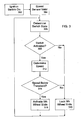
- FIG. 3 is a flow chart of a method of controlling a fifth wheel that may be carried out by execution of suitable program instructions by the ECU 204 or a similar processor. It will be recognized that the illustrated steps may be carried out in the order depicted or in a different order, and FIG. 3 depicts two optional initialization steps.
- step 302 the vehicle's engine ignition switch should be on, rather than off, and in step 304, the speed sensor 202 should be verified as delivering valid measurements. If either of these conditions is not true, then it is currently believed to be preferable that the slide is not released.
- step 306 the state or position of the sliding fifth wheel dash switch 206 is determined. If the dash switch 206 is not activated (No in step 308), the ECU acts such that the slide is not released (step 310), for example by not activating the solenoid 208 or other device that controls air for the sliding fifth wheel 108. If the dash switch 206 is activated (Yes in step 308), the speed of the vehicle is determined (step 312), for example by sensing the speed or a parameter that can be used to compute the speed. If the speed is above the threshold (No in step 314), the ECU acts such that the slide is not released (step 310).
- step 314 If the vehicle's speed is below the threshold and the dash switch 206 is activated (Yes in step 314), the solenoid 208 or other device that controls air for the sliding fifth wheel 108 is activated by an output of the ECU 204 (step 316) so that the position of the fifth wheel can be changed.
- this invention can additionally be considered to be embodied entirely within any form of computer-readable storage medium having stored therein an appropriate set of instructions for use by or in connection with an instruction-execution system, apparatus, or device, such as a computer-based system, processor-containing system, or other system that can fetch instructions from a medium and execute the instructions.
- a "computer-readable medium” can be any means that can contain, store, communicate, propagate, or transport the program for use by or in connection with the instruction-execution system, apparatus, or device.
- the computer-readable medium can be, for example but not limited to, an electronic, magnetic, optical, electromagnetic, infrared, or semiconductor system, apparatus, device, or propagation medium.
- the computer-readable medium include an electrical connection having one or more wires, a portable compute diskette, a random-access memory (RAM), a read-only memory (ROM), an erasable programmable read-only memory (EPROM or Flash memory), and an optical fiber.
- RAM random-access memory
- ROM read-only memory
- EPROM or Flash memory erasable programmable read-only memory
Landscapes
- Engineering & Computer Science (AREA)
- Chemical & Material Sciences (AREA)
- Combustion & Propulsion (AREA)
- Transportation (AREA)
- Mechanical Engineering (AREA)
- Regulating Braking Force (AREA)
- Lock And Its Accessories (AREA)
- Vehicle Body Suspensions (AREA)
- Body Structure For Vehicles (AREA)
- Control Of Vehicle Engines Or Engines For Specific Uses (AREA)
- Endoscopes (AREA)
Abstract
Description
- This invention relates to systems and methods of controlling a vehicle, especially a heavy vehicle such as a highway truck or a tractor, in particular by controlling the vehicle's fifth wheel.
- Over-the-highway trucks and tractor-trailer combinations come in many different sizes and configurations, and the relative geometry of the tractor and trailer in a load-carrying vehicle such as a class-8 tractor-trailer combination can vary widely. For example, the distribution of a tractor-trailer's weight on its axles can vary based on, among other factors, the position of a "fifth wheel" with respect to the cab of the tractor. A "fifth wheel" is generally a wheel or portion of a wheel placed horizontally over the rear axle or axles of a tractor or truck that is a coupling for a trailer.
-
FIG. 1 is a side view of atypical tractor 100 having acab 102, front wheels andaxle 104, a pair of rear wheels andaxles 106, and afifth wheel 108. Some tractors have sliding fifth wheels, which can be used to manage vehicle weight distribution by moving the trailer closer to or farther from the tractor. For example,JP 2003 089365 A U.S. Patent No. 4,429,892 to Frampton et al. describes a device for attachment to a tractor for selectively moving the fifth wheel assembly of the tractor. The device has two drive members that can be extended or contracted from the cab of the tractor to slide the fifth wheel back and forth. - For safety, the fifth wheel should not be permitted to slide when the vehicle is moving.
U.S. Patent No. 6,384,716 to Eckelberry describes a trailer slider positioning alarm. The slider (fifth wheel) is locked in place with a set of pins. A speed sensor detects a speed of the unit and a pin position sensor detects whether any of the pins are unlocked. An alarm sends an alert signal in response to the speed sensor's detection of a predetermined speed and the pin position sensor's detection of at least one unlocked pin. - Some sliding fifth wheels, like other truck components, are actuated by pneumatic pressure that is controlled from the dash in the cab of the tractor. Actuating a switch on the dash locks and unlocks the position of the fifth wheel. The fifth wheel slide lock may be activated by an electrically controlled air solenoid or similar device.
- The pneumatic supply to a bank of air solenoids, including the fifth wheel slide solenoid, usually uses a common feed. Because the air supply is shared by other truck components, a pneumatic interlock cannot be provided for the fifth wheel slide and so the fifth wheel slide can be released at any vehicle speed simply by activating the slide switch on the dash of the truck. If the fifth wheel slide is released while the vehicle is moving, the truck or trailer fifth wheel components could be damaged.
- A vehicle speed interlock can be used to prevent the fifth wheel slide from being unlocked while the vehicle is moving.
- In one aspect of this invention, there is provided a system for controlling a position of a fifth wheel for a vehicle. The system includes a sensor configured to provide an indication of a speed of the vehicle; a switch actuatable to unlock the position of the fifth wheel; and a processor configured to receive the indication of the speed of the vehicle and an indication of a state of the switch. If the vehicle's speed is below a threshold and the switch is actuated to unlock the fifth wheel, the processor generates a control signal that enables the fifth wheel to be unlocked; and if the speed is above the threshold and the switch is actuated to unlock the fifth wheel, the processor generates a control signal that prevents the fifth wheel from being unlocked.
- In another aspect of this invention, there is provided a method of controlling a position of a fifth wheel on a vehicle. The method includes the steps of determining a state of a switch that is actuatable to unlock the position of the fifth wheel; if the state of the switch is actuated to unlock the position of the fifth wheel, then determining a speed of the vehicle; if the speed is below a threshold and the state of the switch is actuated to unlock the position of the fifth wheel, then unlocking the position of the fifth wheel; if the speed is below the threshold and the state of the switch is not actuated to unlock the position of the fifth wheel, then not unlocking the position of the fifth wheel; and if the speed is above the threshold, then not unlocking the position of the fifth wheel.
- In still another aspect of this invention, there is provided a computer-readable medium containing a computer program for controlling a position of a fifth wheel on a vehicle. The computer program carries out the steps of determining a state of a switch that is actuatable to unlock the position of the fifth wheel; if the state of the switch is actuated to unlock the position of the fifth wheel, then determining a speed of the vehicle; if the speed is below a threshold and the state of the switch is actuated to unlock the position of the fifth wheel, then unlocking the position of the fifth wheel; if the speed is below the threshold and the state of the switch is not actuated to unlock the position of the fifth wheel, then not unlocking the position of the fifth wheel; and if the speed is above the threshold, then not unlocking the position of the fifth wheel.
- The various features, objects, and advantages of this invention will be understood by reading this description in conjunction with the drawings, in which:
-
FIG. 1 is a side view of a tractor having a fifth wheel; -
FIG. 2 is a block diagram of control system for a fifth wheel; and -
FIG. 3 is a flow chart of a method of controlling a fifth wheel. - The following description is in terms of a highway truck simply for convenience, and it will be understood that this invention is not limited to such trucks.
- This application recognizes that a speed interlock can prevent a sliding fifth wheel from being unlocked while a vehicle is moving faster than a threshold speed. A vehicle's electronic control unit (ECU) advantageously monitors the vehicle speed and the dash switch that controls the fifth wheel slide. In many modern vehicles, the engine is readily controlled through execution of suitable program instructions by the ECU or a similar electronic processor, which receives input data values, carries out program steps using the input data, and provides output data values to appropriate vehicle systems, such as fuel injectors, ignition timing, engine and wheel brakes, etc.
-
FIG. 2 is a block diagram of asuitable system 200 for controlling a slidingfifth wheel 108. Asuitable sensor 202 provides speed data, either measured or computed, to anECU 204. For example, thespeed sensor 202 may sense the rotational speed of the vehicle's drive shaft or other components in the transmission of the vehicle. Asuitable speed sensor 202 is a magnetic induction sensor, although other types can also be used. The ECU 204 also receives an indication of the state or position of.a sliding fifthwheel dash switch 206, which may be a "hold" switch rather than a toggle switch. If thedash switch 206 is activated to unlock the slidingfifth wheel 108 and the vehicle's speed is above a threshold, the ECU acts such that the slide is not released. As described in more detail below, the slidingfifth wheel 108 can be released only when the vehicle's speed is below a threshold. - For example, the ECU or other suitable processor is programmed such that if the vehicle's speed is below a threshold and the
dash switch 206 is activated, asolenoid 208 or other device that controls air for the slidingfifth wheel 108 is activated by an output of theECU 204. In many vehicles, activation of thesolenoid 208 causes anactuator 210 to release the slidingfifth wheel 108, but it will be appreciated that the details of this arrangement are not important to this invention. In response to the signal from the ECU 204 or other processor, the slidingfifth wheel 108 is released and the position of the fifth wheel can be changed. - In general, if the vehicle's speed is above the threshold, which may be about three kilometers/hour (KPH) for example the
ECU 204 is programmed such that it generates a signal that deactivates thefifth wheel solenoid 208 regardless of the position or state of thedash switch 206. Thus, the fifth wheel is locked in position and cannot be released. it may be noted that different thresholds can be provided for locking and unlocking the position of the fifth wheel, and such hysteresis could be used to provide a greater safety margin for when a vehicle begins to move, but hysteresis is not necessary. Moreover, a threshold higher than 3 KPH may be used. - If the
solenoid 208 andactuator 210 have been deactivated because the vehicle speed was above the threshold and the speed has decreased below the threshold and the fifthwheel slide switch 206 is still applied, it is currently believed to be advantageous for thesolenoid 208 andactuator 210 to remain deactivated until theswitch 206 has been toggled off and back on. Thus, the fifth wheel position can be changed only if the vehicle speed is below the threshold and theswitch 206 is activated. - It will be understood that if the vehicle speed signal is faulty or lost, the
system 200 operates such that the fifth wheel position cannot be unlocked. This arrangement is currently believed to be preferable to an arrangement in which the threshold is such that the truck can be moved at lower speed to change the slide position. One advantage of the preferable arrangement is that inability to unlock the slide, e.g., due to a faulty or tampered-withspeed sensor 202, is a strong inducement to maintain and repair the speed sensor. - The ECU 204 is advantageously programmed to test the
speed sensor 202 and thereby determine whether the sensor readings are valid. The ECU 204 can electrically test whether the sensor has failed, e.g., as an electrical short or open circuit. The ECU 204 can also determine whether thesensor 202 has been tampered with. One exemplary way this can be done is by comparing speed values generated by thesensor 202 with speed values measured by other devices on the vehicle, e.g., an anti-lock brake system. - It will thus be understood that the
system 200 prevents the fifth wheel from being unlocked if the vehicle speed is above a threshold. If the slide is unlocked and the vehicle starts to move too fast, the slide is locked. It is currently believed that the programming of theECU 204 should permit the speed-sensitive locking to be disabled, for example by setting one or more parameters. Moreover, theECU 204 may be programmed to set a fault code and monitor one or more other sensors of the vehicle speed in a suitable fallback mode. -
FIG. 3 is a flow chart of a method of controlling a fifth wheel that may be carried out by execution of suitable program instructions by theECU 204 or a similar processor. It will be recognized that the illustrated steps may be carried out in the order depicted or in a different order, andFIG. 3 depicts two optional initialization steps. Instep 302, the vehicle's engine ignition switch should be on, rather than off, and instep 304, thespeed sensor 202 should be verified as delivering valid measurements. If either of these conditions is not true, then it is currently believed to be preferable that the slide is not released. - In
step 306, the state or position of the sliding fifthwheel dash switch 206 is determined. If thedash switch 206 is not activated (No in step 308), the ECU acts such that the slide is not released (step 310), for example by not activating thesolenoid 208 or other device that controls air for the slidingfifth wheel 108. If thedash switch 206 is activated (Yes in step 308), the speed of the vehicle is determined (step 312), for example by sensing the speed or a parameter that can be used to compute the speed. If the speed is above the threshold (No in step 314), the ECU acts such that the slide is not released (step 310). If the vehicle's speed is below the threshold and thedash switch 206 is activated (Yes in step 314), thesolenoid 208 or other device that controls air for the slidingfifth wheel 108 is activated by an output of the ECU 204 (step 316) so that the position of the fifth wheel can be changed. - It is expected that this invention can be implemented in a wide variety of environments, including for example trucks and other vehicles. It will also be appreciated that procedures described above are carried out repetitively as necessary. To facilitate understanding, aspects of the invention are described in terms of sequences of actions that can be performed by, for example, elements of a programmable computer system. It will be recognized that various actions could be performed by specialized circuits (e.g., discrete logic gates interconnected to perform a specialized function or application-specific integrated circuits), by program instructions executed by one or more processors, or by a combination of both.
- Moreover, this invention can additionally be considered to be embodied entirely within any form of computer-readable storage medium having stored therein an appropriate set of instructions for use by or in connection with an instruction-execution system, apparatus, or device, such as a computer-based system, processor-containing system, or other system that can fetch instructions from a medium and execute the instructions. As used here, a "computer-readable medium" can be any means that can contain, store, communicate, propagate, or transport the program for use by or in connection with the instruction-execution system, apparatus, or device. The computer-readable medium can be, for example but not limited to, an electronic, magnetic, optical, electromagnetic, infrared, or semiconductor system, apparatus, device, or propagation medium. More specific examples (a non-exhaustive list) of the computer-readable medium include an electrical connection having one or more wires, a portable compute diskette, a random-access memory (RAM), a read-only memory (ROM), an erasable programmable read-only memory (EPROM or Flash memory), and an optical fiber.
- It is emphasized that the terms "comprises" and "comprising", when used in this application, specify the presence of stated features, integers, steps, or components and do not preclude the presence or addition of one or more other features, integers, steps, components, or groups thereof.
- Thus, this invention may be embodied in many different forms, not all of which are described above, and all such forms are contemplated to be within the scope of the invention. The particular embodiments described above are merely illustrative and should not be considered restrictive in any way. The scope of the invention is determined by the following claims, and all variations and equivalents that fall within the range of the claims are intended to be embraced therein.
Claims (15)
- A system (200) for controlling a position of a fifth wheel (108) for a vehicle (100), comprising:a sensor (202) configured to provide an indication of a speed of the vehicle (100);a switch (206) actuatable to unlock the position of the fifth wheel (108), enabling the fifth wheel to slide closer to or farther from a cab of the vehicle (100);
anda processor (204) configured to receive the indication of the speed of the vehicle (100) and an indication of a state of the switch (206);
characterized in
that if the speed is below a threshold and the switch (206) is actuated to unlock the fifth wheel (108), the processor (204) generates a control signal that enables the fifth wheel (108) to be unlocked; and if the speed is above the threshold and the switch is (206) actuated to unlock the fifth wheel (108), the processor (204) generates a control signal that prevents the fifth wheel (108) from being unlocked. - The system (200) of claim 1, wherein the sensor (202) provides an indication of a rotational speed of a drive shaft of the vehicle (140).
- The system (200) of claim 1, wherein the switch (206) actuates a device that controls a pressurized air supply for the fifth wheel (108).
- The system (200) of claim 3, wherein if the speed is above the threshold, the processor (204) generates a signal that deactivates the device that controls the pressurized air supply regardless of the state of the switch (206).
- The system of claim 1, wherein if the speed decreases below the threshold and the switch (206) is still actuated to unlock the fifth wheel (108), the processor causes the fifth wheel (108) to remain locked until the switch (206) is toggled off and back on.
- A method of controlling a position of a fifth wheel (108) on a vehicle (100), comprising the steps of:determining a state of a switch (206) that is actuatable to unlock the position of the fifth wheel (108);if the state of the switch (206) is actuated to unlock the position of the fifth wheel (108), then determining a speed of the vehicle (100)
characterized in the steps ofif the speed is below a threshold and the state of the switch (206) is actuated to unlock the position of the fifth wheel (108), then unlocking the position of the fifth wheel (108);if the speed is below the threshold and the state of the switch (206) is not actuated to unlock the position of the fifth wheel (108), then not unlocking the position of the fifth wheel (108); andif the speed is above the threshold, then not unlocking the position of the fifth wheel (108). - The method of claim 6, wherein the speed is determined by sensing a rotational speed of a drive shaft of the vehicle (100).
- The method of claim 6, wherein unlocking the position of the fifth wheel (108) comprises actuating a device that controls a pressurized air supply for the fifth wheel (108).
- The method of claim 8, wherein if the speed is above the threshold, the device that controls the pressurized air supply is deactivated regardless of the state of the switch (206).
- The method of claim 6, wherein if the speed decreases below the threshold and the switch (206) is still actuated to unlock the fifth wheel (108), keeping the fifth wheel position not unlocked until the switch (206) is toggled off and back on.
- A computer-readable medium containing a computer program for controlling a position of a fifth wheel (108) on a vehicle (100), the computer program carrying out the steps of:determining a state of a switch (206) that is actuatable to unlock the position of the fifth wheel (108);if the state of the switch (206) is actuated to unlock the position of the fifth wheel (108), then determining a speed of the vehicle (100)
characterized in the steps ofif the speed is below a threshold and the state of the switch is actuated to unlock the position of the fifth wheel (108), then unlocking the position of the fifth wheel (108);if the speed is below the threshold and the state of the switch (206) is not actuated to unlock the position of the fifth wheel (108), then not unlocking the position of the fifth wheel (108); andif the speed is above the threshold, then not unlocking the position of the fifth wheel (108). - The computer-readable medium of claim 11, wherein the speed is determined by sensing a rotational speed of a drive shaft of the vehicle (100).
- The computer-readable medium of claim 11, wherein unlocking the position of the fifth wheel (108) comprises actuating a device that controls a pressurized air supply for the fifth wheel (108).
- The computer-readable medium of claim 13, wherein if the speed is above the threshold, the device that controls the pressurized air supply is deactivated regardless of the state of the switch (206).
- The computer-readable medium of claim 11, wherein if the speed decreases below the threshold and the switch (206) is still actuated to unlock the fifth wheel (108), keeping the fifth wheel position locked until the switch (206) is toggled off and back on.
Applications Claiming Priority (1)
| Application Number | Priority Date | Filing Date | Title |
|---|---|---|---|
| PCT/US2005/047112 WO2007075165A2 (en) | 2005-12-27 | 2005-12-27 | Fifth wheel slide interlock |
Publications (3)
| Publication Number | Publication Date |
|---|---|
| EP1968846A2 EP1968846A2 (en) | 2008-09-17 |
| EP1968846A4 EP1968846A4 (en) | 2009-06-24 |
| EP1968846B1 true EP1968846B1 (en) | 2010-08-18 |
Family
ID=38218398
Family Applications (1)
| Application Number | Title | Priority Date | Filing Date |
|---|---|---|---|
| EP05855635A Expired - Lifetime EP1968846B1 (en) | 2005-12-27 | 2005-12-27 | Fifth wheel slide interlock |
Country Status (5)
| Country | Link |
|---|---|
| US (1) | US7715970B2 (en) |
| EP (1) | EP1968846B1 (en) |
| AT (1) | ATE477990T1 (en) |
| DE (1) | DE602005023079D1 (en) |
| WO (1) | WO2007075165A2 (en) |
Cited By (6)
| Publication number | Priority date | Publication date | Assignee | Title |
|---|---|---|---|---|
| US10670479B2 (en) | 2018-02-27 | 2020-06-02 | Methode Electronics, Inc. | Towing systems and methods using magnetic field sensing |
| US10696109B2 (en) | 2017-03-22 | 2020-06-30 | Methode Electronics Malta Ltd. | Magnetolastic based sensor assembly |
| US11084342B2 (en) | 2018-02-27 | 2021-08-10 | Methode Electronics, Inc. | Towing systems and methods using magnetic field sensing |
| US11135882B2 (en) | 2018-02-27 | 2021-10-05 | Methode Electronics, Inc. | Towing systems and methods using magnetic field sensing |
| US11221262B2 (en) | 2018-02-27 | 2022-01-11 | Methode Electronics, Inc. | Towing systems and methods using magnetic field sensing |
| US11491832B2 (en) | 2018-02-27 | 2022-11-08 | Methode Electronics, Inc. | Towing systems and methods using magnetic field sensing |
Families Citing this family (6)
| Publication number | Priority date | Publication date | Assignee | Title |
|---|---|---|---|---|
| SE533257C2 (en) * | 2008-12-02 | 2010-08-03 | Scania Cv Ab | Method and system for controlling the offset position of a turntable |
| US20130305943A1 (en) * | 2011-02-08 | 2013-11-21 | Lg Chem, Ltd. | Ink composition for printing, and printing method using same |
| US8463462B2 (en) * | 2011-09-02 | 2013-06-11 | Goodrich Corporation | Systems and methods for braking system testing |
| DE102011118167A1 (en) * | 2011-11-10 | 2013-05-16 | Wabco Gmbh | Adjustment of the vertical load of a center-axle trailer |
| FR3013607B1 (en) * | 2013-11-27 | 2016-04-29 | Genesink Sas | INK COMPOSITION BASED ON NANOPARTICLES |
| US11014417B2 (en) | 2018-02-27 | 2021-05-25 | Methode Electronics, Inc. | Towing systems and methods using magnetic field sensing |
Family Cites Families (5)
| Publication number | Priority date | Publication date | Assignee | Title |
|---|---|---|---|---|
| US4429892A (en) | 1981-06-25 | 1984-02-07 | Frampton William H | Sliding fifth wheel |
| US6384716B1 (en) | 2000-03-06 | 2002-05-07 | Meritor Heavy Vehicle Systems, Llc | Trailer slider repositioning alarm |
| US6793233B2 (en) * | 2000-06-15 | 2004-09-21 | Meritor Heavy Technology, Llc | Trailer slider pin control system |
| JP3681679B2 (en) | 2001-07-13 | 2005-08-10 | 日野自動車株式会社 | Slide-type connected towing device |
| US7156410B1 (en) * | 2005-01-27 | 2007-01-02 | Gus Maskaleris | Automated stabilizing system for fifth wheel plate assemblies |
-
2005
- 2005-12-27 AT AT05855635T patent/ATE477990T1/en not_active IP Right Cessation
- 2005-12-27 US US12/158,746 patent/US7715970B2/en not_active Expired - Fee Related
- 2005-12-27 DE DE602005023079T patent/DE602005023079D1/en not_active Expired - Lifetime
- 2005-12-27 EP EP05855635A patent/EP1968846B1/en not_active Expired - Lifetime
- 2005-12-27 WO PCT/US2005/047112 patent/WO2007075165A2/en not_active Ceased
Cited By (7)
| Publication number | Priority date | Publication date | Assignee | Title |
|---|---|---|---|---|
| US10696109B2 (en) | 2017-03-22 | 2020-06-30 | Methode Electronics Malta Ltd. | Magnetolastic based sensor assembly |
| US10940726B2 (en) | 2017-03-22 | 2021-03-09 | Methode Electronics Malta Ltd. | Magnetoelastic based sensor assembly |
| US10670479B2 (en) | 2018-02-27 | 2020-06-02 | Methode Electronics, Inc. | Towing systems and methods using magnetic field sensing |
| US11084342B2 (en) | 2018-02-27 | 2021-08-10 | Methode Electronics, Inc. | Towing systems and methods using magnetic field sensing |
| US11135882B2 (en) | 2018-02-27 | 2021-10-05 | Methode Electronics, Inc. | Towing systems and methods using magnetic field sensing |
| US11221262B2 (en) | 2018-02-27 | 2022-01-11 | Methode Electronics, Inc. | Towing systems and methods using magnetic field sensing |
| US11491832B2 (en) | 2018-02-27 | 2022-11-08 | Methode Electronics, Inc. | Towing systems and methods using magnetic field sensing |
Also Published As
| Publication number | Publication date |
|---|---|
| US7715970B2 (en) | 2010-05-11 |
| WO2007075165A2 (en) | 2007-07-05 |
| WO2007075165B1 (en) | 2008-08-07 |
| WO2007075165A3 (en) | 2008-06-26 |
| EP1968846A2 (en) | 2008-09-17 |
| DE602005023079D1 (en) | 2010-09-30 |
| US20090024285A1 (en) | 2009-01-22 |
| ATE477990T1 (en) | 2010-09-15 |
| EP1968846A4 (en) | 2009-06-24 |
Similar Documents
| Publication | Publication Date | Title |
|---|---|---|
| US7715970B2 (en) | Fifth wheel slide interlock | |
| USRE43537E1 (en) | Integrated passenger vehicle trailer brake controller | |
| US8260518B2 (en) | Trailer sway control with reverse sensors | |
| US8326504B2 (en) | Holistic control for stabilizing vehicle-trailer swaying | |
| US9834184B2 (en) | Trailer braking system and controller | |
| US6705684B1 (en) | Trailer brake control system with safety function | |
| US20110071736A1 (en) | Slidably adjustable fifth wheel hitch assembly for a vehicle and control system for the same | |
| US20110295470A1 (en) | Tractor trailer gap control system | |
| US20080177454A1 (en) | Integrated trailer brake control system | |
| KR20010013131A (en) | Method and device for stabilizing a vehicle | |
| US20020095253A1 (en) | Vehicle stability control system with tire sensor assembly | |
| BRPI0608876A2 (en) | electronic system for monitoring a trailer hitch set and hitch system | |
| KR102128131B1 (en) | Method for operating an electrically operable parking brake system and control device of an electrically operable parking brake system | |
| CN102387957A (en) | Method and control system for a fifth wheel coupling sliding device having detection of the bent position of towing vehicles and trailers | |
| WO2018035566A1 (en) | Trailer safety systems and methods | |
| US20120193889A1 (en) | Method of Operating a Trailer Braking System | |
| US6819980B2 (en) | Method for the avoidance of rollover phenomena in semitrailers | |
| EP2724876A1 (en) | Towing hook arrangement and method for detecting a load applied to a towing hook | |
| CN218400761U (en) | Trailer in-place hanging auxiliary system | |
| US20190039582A1 (en) | Systems, vehicles, and methods for controlling trailer brake output circuits with a reduced upper limit of trailer brake output signals | |
| US7809486B2 (en) | Pressure boost for vehicle rear brake circuits | |
| WO2010107344A1 (en) | Method for onboard diagnosis of a wheel alignment of a vehicle and vehicle | |
| JP2002054490A (en) | Method of calibrating a vehicle system that operates dependent on sensors | |
| JP2024509811A (en) | Belt retractor unit and vehicle having such a belt retractor unit | |
| US20220161770A1 (en) | Systems for anti-lock braking for a tow vehicle |
Legal Events
| Date | Code | Title | Description |
|---|---|---|---|
| PUAI | Public reference made under article 153(3) epc to a published international application that has entered the european phase |
Free format text: ORIGINAL CODE: 0009012 |
|
| AK | Designated contracting states |
Kind code of ref document: A2 Designated state(s): AT BE BG CH CY CZ DE DK EE ES FI FR GB GR HU IE IS IT LI LT LU LV MC NL PL PT RO SE SI SK TR |
|
| AX | Request for extension of the european patent |
Extension state: AL BA HR MK YU |
|
| 17P | Request for examination filed |
Effective date: 20081229 |
|
| RBV | Designated contracting states (corrected) |
Designated state(s): AT BE BG CH CY CZ DE DK EE ES FI FR GB GR HU IE IS IT LI LT LU LV MC NL PL PT RO SE SI SK TR |
|
| A4 | Supplementary search report drawn up and despatched |
Effective date: 20090528 |
|
| RIC1 | Information provided on ipc code assigned before grant |
Ipc: B62D 53/08 20060101AFI20090520BHEP |
|
| 17Q | First examination report despatched |
Effective date: 20090819 |
|
| GRAP | Despatch of communication of intention to grant a patent |
Free format text: ORIGINAL CODE: EPIDOSNIGR1 |
|
| DAX | Request for extension of the european patent (deleted) | ||
| GRAS | Grant fee paid |
Free format text: ORIGINAL CODE: EPIDOSNIGR3 |
|
| GRAA | (expected) grant |
Free format text: ORIGINAL CODE: 0009210 |
|
| AK | Designated contracting states |
Kind code of ref document: B1 Designated state(s): AT BE BG CH CY CZ DE DK EE ES FI FR GB GR HU IE IS IT LI LT LU LV MC NL PL PT RO SE SI SK TR |
|
| REG | Reference to a national code |
Ref country code: GB Ref legal event code: FG4D |
|
| REG | Reference to a national code |
Ref country code: CH Ref legal event code: EP |
|
| REG | Reference to a national code |
Ref country code: IE Ref legal event code: FG4D |
|
| REF | Corresponds to: |
Ref document number: 602005023079 Country of ref document: DE Date of ref document: 20100930 Kind code of ref document: P |
|
| REG | Reference to a national code |
Ref country code: SE Ref legal event code: TRGR |
|
| REG | Reference to a national code |
Ref country code: NL Ref legal event code: VDEP Effective date: 20100818 |
|
| LTIE | Lt: invalidation of european patent or patent extension |
Effective date: 20100818 |
|
| PG25 | Lapsed in a contracting state [announced via postgrant information from national office to epo] |
Ref country code: LT Free format text: LAPSE BECAUSE OF FAILURE TO SUBMIT A TRANSLATION OF THE DESCRIPTION OR TO PAY THE FEE WITHIN THE PRESCRIBED TIME-LIMIT Effective date: 20100818 Ref country code: AT Free format text: LAPSE BECAUSE OF FAILURE TO SUBMIT A TRANSLATION OF THE DESCRIPTION OR TO PAY THE FEE WITHIN THE PRESCRIBED TIME-LIMIT Effective date: 20100818 Ref country code: FI Free format text: LAPSE BECAUSE OF FAILURE TO SUBMIT A TRANSLATION OF THE DESCRIPTION OR TO PAY THE FEE WITHIN THE PRESCRIBED TIME-LIMIT Effective date: 20100818 |
|
| PG25 | Lapsed in a contracting state [announced via postgrant information from national office to epo] |
Ref country code: PT Free format text: LAPSE BECAUSE OF FAILURE TO SUBMIT A TRANSLATION OF THE DESCRIPTION OR TO PAY THE FEE WITHIN THE PRESCRIBED TIME-LIMIT Effective date: 20101220 Ref country code: PL Free format text: LAPSE BECAUSE OF FAILURE TO SUBMIT A TRANSLATION OF THE DESCRIPTION OR TO PAY THE FEE WITHIN THE PRESCRIBED TIME-LIMIT Effective date: 20100818 Ref country code: IS Free format text: LAPSE BECAUSE OF FAILURE TO SUBMIT A TRANSLATION OF THE DESCRIPTION OR TO PAY THE FEE WITHIN THE PRESCRIBED TIME-LIMIT Effective date: 20101218 Ref country code: BG Free format text: LAPSE BECAUSE OF FAILURE TO SUBMIT A TRANSLATION OF THE DESCRIPTION OR TO PAY THE FEE WITHIN THE PRESCRIBED TIME-LIMIT Effective date: 20101118 Ref country code: CY Free format text: LAPSE BECAUSE OF FAILURE TO SUBMIT A TRANSLATION OF THE DESCRIPTION OR TO PAY THE FEE WITHIN THE PRESCRIBED TIME-LIMIT Effective date: 20100818 Ref country code: SI Free format text: LAPSE BECAUSE OF FAILURE TO SUBMIT A TRANSLATION OF THE DESCRIPTION OR TO PAY THE FEE WITHIN THE PRESCRIBED TIME-LIMIT Effective date: 20100818 |
|
| PG25 | Lapsed in a contracting state [announced via postgrant information from national office to epo] |
Ref country code: LV Free format text: LAPSE BECAUSE OF FAILURE TO SUBMIT A TRANSLATION OF THE DESCRIPTION OR TO PAY THE FEE WITHIN THE PRESCRIBED TIME-LIMIT Effective date: 20100818 Ref country code: NL Free format text: LAPSE BECAUSE OF FAILURE TO SUBMIT A TRANSLATION OF THE DESCRIPTION OR TO PAY THE FEE WITHIN THE PRESCRIBED TIME-LIMIT Effective date: 20100818 Ref country code: BE Free format text: LAPSE BECAUSE OF FAILURE TO SUBMIT A TRANSLATION OF THE DESCRIPTION OR TO PAY THE FEE WITHIN THE PRESCRIBED TIME-LIMIT Effective date: 20100818 Ref country code: GR Free format text: LAPSE BECAUSE OF FAILURE TO SUBMIT A TRANSLATION OF THE DESCRIPTION OR TO PAY THE FEE WITHIN THE PRESCRIBED TIME-LIMIT Effective date: 20101119 |
|
| PG25 | Lapsed in a contracting state [announced via postgrant information from national office to epo] |
Ref country code: DK Free format text: LAPSE BECAUSE OF FAILURE TO SUBMIT A TRANSLATION OF THE DESCRIPTION OR TO PAY THE FEE WITHIN THE PRESCRIBED TIME-LIMIT Effective date: 20100818 |
|
| PG25 | Lapsed in a contracting state [announced via postgrant information from national office to epo] |
Ref country code: IT Free format text: LAPSE BECAUSE OF FAILURE TO SUBMIT A TRANSLATION OF THE DESCRIPTION OR TO PAY THE FEE WITHIN THE PRESCRIBED TIME-LIMIT Effective date: 20100818 Ref country code: SK Free format text: LAPSE BECAUSE OF FAILURE TO SUBMIT A TRANSLATION OF THE DESCRIPTION OR TO PAY THE FEE WITHIN THE PRESCRIBED TIME-LIMIT Effective date: 20100818 Ref country code: EE Free format text: LAPSE BECAUSE OF FAILURE TO SUBMIT A TRANSLATION OF THE DESCRIPTION OR TO PAY THE FEE WITHIN THE PRESCRIBED TIME-LIMIT Effective date: 20100818 Ref country code: RO Free format text: LAPSE BECAUSE OF FAILURE TO SUBMIT A TRANSLATION OF THE DESCRIPTION OR TO PAY THE FEE WITHIN THE PRESCRIBED TIME-LIMIT Effective date: 20100818 Ref country code: CZ Free format text: LAPSE BECAUSE OF FAILURE TO SUBMIT A TRANSLATION OF THE DESCRIPTION OR TO PAY THE FEE WITHIN THE PRESCRIBED TIME-LIMIT Effective date: 20100818 |
|
| PLBE | No opposition filed within time limit |
Free format text: ORIGINAL CODE: 0009261 |
|
| STAA | Information on the status of an ep patent application or granted ep patent |
Free format text: STATUS: NO OPPOSITION FILED WITHIN TIME LIMIT |
|
| PG25 | Lapsed in a contracting state [announced via postgrant information from national office to epo] |
Ref country code: ES Free format text: LAPSE BECAUSE OF FAILURE TO SUBMIT A TRANSLATION OF THE DESCRIPTION OR TO PAY THE FEE WITHIN THE PRESCRIBED TIME-LIMIT Effective date: 20101129 |
|
| 26N | No opposition filed |
Effective date: 20110519 |
|
| PG25 | Lapsed in a contracting state [announced via postgrant information from national office to epo] |
Ref country code: MC Free format text: LAPSE BECAUSE OF NON-PAYMENT OF DUE FEES Effective date: 20101231 |
|
| REG | Reference to a national code |
Ref country code: CH Ref legal event code: PL |
|
| REG | Reference to a national code |
Ref country code: DE Ref legal event code: R097 Ref document number: 602005023079 Country of ref document: DE Effective date: 20110519 |
|
| PG25 | Lapsed in a contracting state [announced via postgrant information from national office to epo] |
Ref country code: CH Free format text: LAPSE BECAUSE OF NON-PAYMENT OF DUE FEES Effective date: 20101231 Ref country code: IE Free format text: LAPSE BECAUSE OF NON-PAYMENT OF DUE FEES Effective date: 20101227 Ref country code: LI Free format text: LAPSE BECAUSE OF NON-PAYMENT OF DUE FEES Effective date: 20101231 |
|
| PG25 | Lapsed in a contracting state [announced via postgrant information from national office to epo] |
Ref country code: HU Free format text: LAPSE BECAUSE OF FAILURE TO SUBMIT A TRANSLATION OF THE DESCRIPTION OR TO PAY THE FEE WITHIN THE PRESCRIBED TIME-LIMIT Effective date: 20110219 Ref country code: LU Free format text: LAPSE BECAUSE OF NON-PAYMENT OF DUE FEES Effective date: 20101227 |
|
| PG25 | Lapsed in a contracting state [announced via postgrant information from national office to epo] |
Ref country code: TR Free format text: LAPSE BECAUSE OF FAILURE TO SUBMIT A TRANSLATION OF THE DESCRIPTION OR TO PAY THE FEE WITHIN THE PRESCRIBED TIME-LIMIT Effective date: 20100818 |
|
| PGFP | Annual fee paid to national office [announced via postgrant information from national office to epo] |
Ref country code: GB Payment date: 20121227 Year of fee payment: 8 Ref country code: SE Payment date: 20121217 Year of fee payment: 8 |
|
| PGFP | Annual fee paid to national office [announced via postgrant information from national office to epo] |
Ref country code: FR Payment date: 20130107 Year of fee payment: 8 |
|
| PGFP | Annual fee paid to national office [announced via postgrant information from national office to epo] |
Ref country code: DE Payment date: 20121219 Year of fee payment: 8 |
|
| REG | Reference to a national code |
Ref country code: DE Ref legal event code: R119 Ref document number: 602005023079 Country of ref document: DE |
|
| REG | Reference to a national code |
Ref country code: SE Ref legal event code: EUG |
|
| GBPC | Gb: european patent ceased through non-payment of renewal fee |
Effective date: 20131227 |
|
| PG25 | Lapsed in a contracting state [announced via postgrant information from national office to epo] |
Ref country code: SE Free format text: LAPSE BECAUSE OF NON-PAYMENT OF DUE FEES Effective date: 20131228 |
|
| REG | Reference to a national code |
Ref country code: DE Ref legal event code: R119 Ref document number: 602005023079 Country of ref document: DE Effective date: 20140701 |
|
| REG | Reference to a national code |
Ref country code: FR Ref legal event code: ST Effective date: 20140829 |
|
| PG25 | Lapsed in a contracting state [announced via postgrant information from national office to epo] |
Ref country code: DE Free format text: LAPSE BECAUSE OF NON-PAYMENT OF DUE FEES Effective date: 20140701 |
|
| PG25 | Lapsed in a contracting state [announced via postgrant information from national office to epo] |
Ref country code: FR Free format text: LAPSE BECAUSE OF NON-PAYMENT OF DUE FEES Effective date: 20131231 Ref country code: GB Free format text: LAPSE BECAUSE OF NON-PAYMENT OF DUE FEES Effective date: 20131227 |