EP1968313A1 - Electronic program guide generation - Google Patents
Electronic program guide generation Download PDFInfo
- Publication number
- EP1968313A1 EP1968313A1 EP07250827A EP07250827A EP1968313A1 EP 1968313 A1 EP1968313 A1 EP 1968313A1 EP 07250827 A EP07250827 A EP 07250827A EP 07250827 A EP07250827 A EP 07250827A EP 1968313 A1 EP1968313 A1 EP 1968313A1
- Authority
- EP
- European Patent Office
- Prior art keywords
- events
- receiver
- blocks
- decoder
- program guide
- Prior art date
- Legal status (The legal status is an assumption and is not a legal conclusion. Google has not performed a legal analysis and makes no representation as to the accuracy of the status listed.)
- Granted
Links
Images

Classifications
-
- H—ELECTRICITY
- H04—ELECTRIC COMMUNICATION TECHNIQUE
- H04N—PICTORIAL COMMUNICATION, e.g. TELEVISION
- H04N21/00—Selective content distribution, e.g. interactive television or video on demand [VOD]
- H04N21/40—Client devices specifically adapted for the reception of or interaction with content, e.g. set-top-box [STB]; Operations thereof
- H04N21/47—End-user applications
- H04N21/482—End-user interface for programme selection
-
- H—ELECTRICITY
- H04—ELECTRIC COMMUNICATION TECHNIQUE
- H04N—PICTORIAL COMMUNICATION, e.g. TELEVISION
- H04N21/00—Selective content distribution, e.g. interactive television or video on demand [VOD]
- H04N21/40—Client devices specifically adapted for the reception of or interaction with content, e.g. set-top-box [STB]; Operations thereof
- H04N21/43—Processing of content or additional data, e.g. demultiplexing additional data from a digital video stream; Elementary client operations, e.g. monitoring of home network or synchronising decoder's clock; Client middleware
- H04N21/431—Generation of visual interfaces for content selection or interaction; Content or additional data rendering
- H04N21/4312—Generation of visual interfaces for content selection or interaction; Content or additional data rendering involving specific graphical features, e.g. screen layout, special fonts or colors, blinking icons, highlights or animations
-
- H—ELECTRICITY
- H04—ELECTRIC COMMUNICATION TECHNIQUE
- H04N—PICTORIAL COMMUNICATION, e.g. TELEVISION
- H04N21/00—Selective content distribution, e.g. interactive television or video on demand [VOD]
- H04N21/40—Client devices specifically adapted for the reception of or interaction with content, e.g. set-top-box [STB]; Operations thereof
- H04N21/43—Processing of content or additional data, e.g. demultiplexing additional data from a digital video stream; Elementary client operations, e.g. monitoring of home network or synchronising decoder's clock; Client middleware
- H04N21/443—OS processes, e.g. booting an STB, implementing a Java virtual machine in an STB or power management in an STB
- H04N21/4438—Window management, e.g. event handling following interaction with the user interface
-
- H—ELECTRICITY
- H04—ELECTRIC COMMUNICATION TECHNIQUE
- H04N—PICTORIAL COMMUNICATION, e.g. TELEVISION
- H04N21/00—Selective content distribution, e.g. interactive television or video on demand [VOD]
- H04N21/40—Client devices specifically adapted for the reception of or interaction with content, e.g. set-top-box [STB]; Operations thereof
- H04N21/47—End-user applications
Definitions
- the present invention relates generally to digital television and specifically to a receiver-decoder for receiving and decoding a broadcast digital television signal.
- Digital television signals are broadcast in encoded form, for example in accordance with the MPEG-2 or MPEG-4 standard.
- Reception is performed by a receiver-decoder apparatus which includes a receiver-decoder circuit which receives the broadcast television signal and decodes it into a format in which allowing display by a display device.
- the receiver-decoder apparatus may be a television apparatus incorporating the display device or may be a separate apparatus, such as a set-top box, which supplies the decoded television signal to a television apparatus.
- An Electronic Program Guide is a guide displayed on the display device of the television apparatus to show a list of television programs (hereinafter called “events") which are available to watch on the various television channels (hereinafter called “services”) over a given period of time.
- An EPG is an on-screen guide giving information about events on respective services that either are currently being broadcast or are due to be subsequently broadcast. The information typically includes the name of the service and the name and times of the events. It may include further information such as a brief synopsis of the event.
- signalling data representing the content of the EPG is broadcast together with the broadcast television signal.
- the signalling data may be time-multiplexed within the broadcast television signal as occurs in the DVB standard or may be transmitted on a separate channel as occurs in the ATSC standard.
- the receiver-decoder apparatus extracts the signalling data and uses it to generate an EPG.
- a receiver-decoder apparatus comprising:
- EPG generation means for extracting signalling data broadcast with the broadcast television signal and received by the receiver-decoder to generate therefrom a signal for display of an electronic program guide on said display device, the electronic program guide including a list of the services available for reception by the receiver-decoder circuit and events in respect of those services, wherein the EPG generation means is arranged to identify within the services available for reception by the receiver-decoder circuit further events which are related to respective events in the electronic program guide, and the EPG generation means is arranged to generate a signal for display of an electronic program guide in which the further events are shown associated with the events to which they are related.
- the EPG As a result it is possible for the EPG to indicate further events which are related to respective events within the services. This allows the user to be presented with a choice of related events. This increases the choice of television content for the user because the user can immediately appreciate the existence of the further events.
- the further events could have been broadcast in other services even without implementing the present invention, but in that case there would have been a risk of the user failing to notice the further events due to the large number of services typically available.
- the broadcast television signal comprises a stream of packets of data multiplexed together and carried modulated onto a radio frequency (RF) carrier signal in a single RF channel.
- the stream is sometimes referred to as a channel because it corresponds to a transmission channel.
- the stream contains packets of video signal data, packets of audio signal data and packets of signalling data.
- Each packet of signalling data is associated with a particular table, the arrangement and content of which is in accordance with those defined in the standards ISO/IEC 13818-1 and EN 300 468.
- each of the signalling data packets has a packet identifier (PID) which designates it as a packet of signalling data, rather than a packet of audio or visual data.
- PID packet identifier
- table identifier which designates which table the packet belongs to.
- Each signalling data packet also contains a "payload", which contains data about, for example, the network, the services and/or the events. The precise items of data that are stored in a packet depend on which table the packet belongs to, and details of which items of data are given in packets belonging to a particular table can be found in the standards.
- the signalling data includes the following information which can be extracted for use as the content of an EPG:
- the broadcast television signals are encoded in accordance with the MPEG-2 standard.
- each broadcast RF channel comprises a plurality of services multiplexed together.
- the encoding may be of any other type, for example in accordance with the MPEG-4 standard.
- Fig. 1 shows a receiver-decoder apparatus 1 which is capable of receiving and decoding broadcast television signals in accordance with the DVB standard and the MPEG-2 standard.
- the receiver-decoder apparatus 1 is a television including a display device 10 but this is not essential.
- the receiver-decoder apparatus 1 could have no display device and instead output a video stream for supply to a separate television apparatus.
- the receiver-decoder apparatus 1 might be a set-top box or a recoding apparatus including a recording device for recording a video signal.
- the receiver-decoder apparatus 1 is connected to an external antenna 3 in a conventional manner.
- the receiver-decoder apparatus 1 has a receiver circuit 4 which is supplied with a radio frequency television broadcast signal received by the antenna 3.
- the receiver circuit 4 comprises an RF tuner 5 which extracts the desired broadcast signal and a demodulator 6 which demodulates the broadcast signal to extract a multiplexed signal of a single broadcast channel.
- the broadcast digital television signal is a terrestrial signal transmitted on a RF carrier.
- the broadcast digital television signal could be a satellite signal or a cable signal, in which case the antenna 3 and receiver circuit 4 are adapted in a conventional manner to receive such signals.
- each broadcast channel carries a multiplexed signal in which a plurality of video streams and associated audio and data streams, commonly referred to as services, are multiplexed together.
- the video stream extracted by the demodulator 6 is supplied to a demultiplexer 8.
- the demultiplexer 8 demultiplexes the packets of data in the video stream to extract one or more video signals, one or more audio signals and signalling data.
- the video signal extracted by the demultiplexer 8 is supplied to an MPEG-2 decoder 9 for decoding the video stream in accordance with the MPEG-2 standard.
- the MPEG-2 decoder 9 outputs an uncompressed video signal.
- the receiver circuit 4, demultiplexer 8 and decoder 9 together form a receiver-decoder circuit for receiving and decoding the broadcast television signal.
- the video signal from the MPEG-2 decoder 9 is a supplied to the display device 10 which displays the video images of the video stream, or in the case that the display device 10 is absent is output from the receiver-decoder apparatus 1 through a video output interface 12 for supply to a separate television apparatus. If the receiver-decoder apparatus 1 has a recording device, the video signal may be supplied thereto to be recorded.
- the receiver-decoder apparatus 1 includes a controller 13 which controls the operation of the components of the receiver-decoder apparatus 1.
- the controller 13 controls the receiver circuit 4 and the demultiplexer 8 to select the broadcast video signal of a desired service.
- the controller 13 is implemented by a microprocessor running an appropriate program.
- the controller 13 has associated therewith a RAM 14 and a non-volatile memory 15 such as a flash memory.
- the computer program may be stored in the non-volatile memory 15.
- the computer program may be pre-installed or may be transmitted to the recording apparatus 1 as a broadcast signal, this being a known technique for upgrading of software of a television receiving equipment.
- the receiver-decoder apparatus 1 also includes an IR (infra-red) receiver unit 16 capable of receiving signals from a remote commander 17.
- the remote commander 17 is operated by a user to provide user-inputs to the receiver-decoder apparatus 1.
- the user-inputs may be supplied to and interpreted by the controller 13.
- EPG electronic program guide
- the content of the EPG in respect of the broadcast television signals which may be received by the receiver circuit 4 is derived from the signalling data received by the receiver circuit 4 of the receiver-decoder apparatus 1 and output by the demultiplexer 8.
- the controller 13 extracts this signalling data from the signalling data packets output by the demultiplexer 8 and uses it to populate the EPG.
- the EPG includes a list of services available for reception by the receiver circuit 4 and events in respect of those services. Such content is conventional for an EPG in a receiver-decoder apparatus.
- the controller 13 stores data representing the EPG in the memory 14.
- the decoder 9 includes a graphics generator 19.
- the controller 13 controls the graphics generator 19 to generate the video signal representing the EPG stored in the memory 14.
- the EPG may be superimposed on or mixed with the video signal output by the decoder 9, so that they are displayed on the display device 10.
- the video signal may be output from the decoder 9 separately from the output video signal for display on the display device 10.
- the user can view the EPG on the display device 10.
- a traditional EPG is shown in Fig. 2 .
- the EPG is displayed in grid showing a list of services.
- the EPG includes a column of service fields each represented by a block 21 bearing the name of the service.
- the EPG includes a row of event fields each represented by a block 22 bearing information about the events including the names and times of the events.
- the blocks 22 of the individual event fields are arranged along a common time line such that the length of the blocks 22 is indicative of the length of the corresponding event.
- the format of the EPG may be freely designed by the manufacturer of the receiver-decoder apparatus 1 to provide a desired look and feel.
- the EPG of the receiver-decoder apparatus 1 is a modified form of the traditional EPG shown in Fig. 2 as will now be described.
- the controller 13 identifies further events within the services available for reception by the receiver circuit 4. These further events each relate to a respective event in the EPG.
- the further events may be related to the normal events in the EPG in any manner chosen by the broadcaster.
- the further events have content related to the normal events.
- Some examples are as follows.
- the further events may be alternative views of the same content, for example recordings of the same sports event with a different camera angle.
- the further events may be alternative content which is expected to interest the viewer. For example if the normal event is a match in a sports tournament, the further events may be different matches in the same sports tournament, or the further events may contain different or additional content related to the normal event.
- Another possibility is that the further events are abbreviated highlights of the normal event to which they relate. However, these examples are by no means limitative. Indeed a particular advantage of the present invention is that the further events may be related to the normal events in the EPG in any manner whatsoever.
- the controller 13 derives data about the further events and stores it in the memory 14 as part of the data of the electronic program guide.
- the data about the further events may be derived in various manners.
- the data about the further events is extracted as part of the signalling data in the signalling data packets.
- the signalling data includes an additional table beyond the tables normally included as part of the DVB standard.
- the data about the further events is extracted from data transmitted for the purpose of implementing a teletext service, for example data in accordance with the MHEG standard which is a standard for the middleware of interactive digital teletext services in the United Kingdom, or in accordance with the MHP standard which is a similar standard for interactive television used in other European countries.
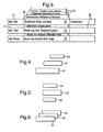
- the further events are shown in the EPG displayed on the display device 10 by modifying the form of the displayed EPG to be as shown in Fig. 3 .
- the displayed EPG has the same basic structure as the traditional EPG shown in Fig. 2 and as described above, in particular including a column of service fields each represented by a block 21 and, in respect of each service, a row of event fields represented by blocks 22.
- the further events are shown by further blocks 23 positioned adjacent the blocks of the events to which they are related.
- the further blocks 23 bear information about the further events including the names and times of the further events.
- the further blocks 23 are arranged relative to the block 22 of the event to which the further events relate to create the appearance of the further blocks 23 being more distant than the blocks 22 of the events to which they are related. Such a view gives the impression of depth. This is of great advantage because the user can immediately appreciate the relationship between the normal events in the services and the related, further events.
- the appearance of the further blocks 23 being more distant than the blocks 22 may be created by a number of techniques. In Fig. 3 , this impression is created by the use of a perspective view and by the further blocks 23 being overlapped by the blocks 22.
- Alternative arrangements for the blocks 22 and the further blocks 23 using a perspective view without overlapping are shown in Figs. 4 and 5 .
- Another alternative arrangement for the blocks 22 and the further blocks 23 using overlapping without a perspective view is shown in Fig. 6 .
- Perspective is how the appearance of things relative to one another changes in accordance with their distance from the viewer.
- the further blocks 23 may be scaled (which means they are changed in size by the same proportion in both dimensions, in this case reduced in size) relative to the blocks 22, to create a perspective view of the further blocks 23 being of the same size as the blocks 22 but arranged more distantly than the blocks 22.
- Use of such a perspective view creates the appearance to the viewer that the further blocks 23 are actually arranged more distantly than the blocks 22, even though the blocks 22 and further blocks 23 are in fact a two-dimensional image. This effect is employed in each of the arrangements of Figs. 3 to 5 .
- the impression of depth may also be created by the further blocks 23 being overlapped by the blocks 22. This creates the impression to the viewer that the further blocks 23 are actually disposed behind the blocks 22, even though the blocks 22 and further blocks 23 are in fact a two-dimensional image. This effect may be employed together with a perspective view as shown in Fig. 3 , but may also be employed by itself with the blocks 22 and further blocks 23 being of the same size as shown in Fig. 6 .
- the format of the displayed EPG is controlled by the controller 13 in response to user-inputs from the remote commander 17 to provide a graphical user interface (GUI).
- GUI graphical user interface
- a curser on the displayed EPG may be moved in response to user-inputs to high-light different services and/or events in the EPG including the normal events and the further events.
- the controller 13 is also responsive to user-inputs from the remote commander 17 which select services and/or events in the EPG.
- the controller 13 controls the receiver-decoder apparatus 1 to receive the selected events, either now if it is a current event or at a point in the future if it is a future event, for example by setting a timer.
- the selected event which is received may be displayed on the display device 10 or output by the video output interface 12.
- the controller 13 may control the receiver-decoder apparatus 1 to cause recording of the selected events, for example by controlling the operation of a recording unit if present in the receiver-decoder apparatus 1 or by outputting a command to an external recording apparatus.
- the controller 13 controls the receiver circuit 4 to receive the selected service and switches the switch 12 to the supply the video stream from the receiver circuit 4 to the demultiplexer 8 and decoder 9.
- the video signal of the selected service is displayed on the display device 10. Where a future event is selected, this operation may be performed subsequently at the time of the event.
- the receiver-decoder apparatus 1 is arranged to receive a radio frequency television broadcast signal, it may be modified to receive any type of broadcast television signal.
- the receiver-decoder apparatus 1 has basically the same structure as shown in Fig. 1 except that the connection to the external antenna 3 is replaced by a connection to the cable.
- a television signal delivered over a network which may be a wired network such as the internet or a LAN or may be a wireless network.
- the television signals may be IPTV (Interenet Protocol television).
- the receiver-decoder apparatus 1 has basically the same structure as shown in Fig. 1 except that the receiver circuit 4 is replaced by a network interface arranged to receive data from the data network and to extract a video stream therefrom.
Landscapes
- Engineering & Computer Science (AREA)
- Multimedia (AREA)
- Signal Processing (AREA)
- Human Computer Interaction (AREA)
- Software Systems (AREA)
- Two-Way Televisions, Distribution Of Moving Picture Or The Like (AREA)
- Control Of Motors That Do Not Use Commutators (AREA)
- Oscillators With Electromechanical Resonators (AREA)
- Television Systems (AREA)
- Circuits Of Receivers In General (AREA)
- Stored Programmes (AREA)
Abstract
Description
- The present invention relates generally to digital television and specifically to a receiver-decoder for receiving and decoding a broadcast digital television signal.
- Digital television signals are broadcast in encoded form, for example in accordance with the MPEG-2 or MPEG-4 standard. Reception is performed by a receiver-decoder apparatus which includes a receiver-decoder circuit which receives the broadcast television signal and decodes it into a format in which allowing display by a display device. The receiver-decoder apparatus may be a television apparatus incorporating the display device or may be a separate apparatus, such as a set-top box, which supplies the decoded television signal to a television apparatus.
- An Electronic Program Guide (EPG) is a guide displayed on the display device of the television apparatus to show a list of television programs (hereinafter called "events") which are available to watch on the various television channels (hereinafter called "services") over a given period of time. An EPG is an on-screen guide giving information about events on respective services that either are currently being broadcast or are due to be subsequently broadcast. The information typically includes the name of the service and the name and times of the events. It may include further information such as a brief synopsis of the event.
- To allow generation of the EPG, signalling data representing the content of the EPG is broadcast together with the broadcast television signal. The signalling data may be time-multiplexed within the broadcast television signal as occurs in the DVB standard or may be transmitted on a separate channel as occurs in the ATSC standard. The receiver-decoder apparatus extracts the signalling data and uses it to generate an EPG.
- There is a trend towards interactive television in which the user is able to interactively select television content to watch. Ultimately this might be provided by on-demand download of television content, but at present there are infrastructure and practical constraints which mean this is not generally available to consumers. Therefore other, simpler means of enhancing the choice of television for users is desirable.
- According to the present invention, there is provided a receiver-decoder apparatus, comprising:
- a receiver-decoder circuit capable of receiving and decoding broadcast television signals of different services to generate therefrom a video signal for display of an image on a display device; and
- EPG generation means for extracting signalling data broadcast with the broadcast television signal and received by the receiver-decoder to generate therefrom a signal for display of an electronic program guide on said display device, the electronic program guide including a list of the services available for reception by the receiver-decoder circuit and events in respect of those services,
wherein the EPG generation means is arranged to identify within the services available for reception by the receiver-decoder circuit further events which are related to respective events in the electronic program guide, and the EPG generation means is arranged to generate a signal for display of an electronic program guide in which the further events are shown associated with the events to which they are related. - As a result it is possible for the EPG to indicate further events which are related to respective events within the services. This allows the user to be presented with a choice of related events. This increases the choice of television content for the user because the user can immediately appreciate the existence of the further events. Of course the further events could have been broadcast in other services even without implementing the present invention, but in that case there would have been a risk of the user failing to notice the further events due to the large number of services typically available.
- To allow better understanding, an embodiment of the present invention will now be described by way of non-limitative example with reference to the accompanying drawings, in which:
-
Fig. 1 is a diagram of a receiver-decoder apparatus; -
Fig. 2 shows a traditional electronic program guide; -
Fig. 3 shows an electronic programme guide in accordance with the present invention; and -
Figs. 4 to 6 show alternative arrangements of the blocks in an electronic program guide. - By way of example a description will be given of an embodiment working with broadcast television signals in accordance with the DVB standard. First the nature of the broadcast television signals will be described.
- According to the DVB standard, what a user might normally call a "channel" is known as a "service". For example, in the UK, BBC1 would be one service and BBC2 would be another service. Also according to the DVB standard, what a user might normally call a "program" is known as an "event". These occupy individual time slots within a service. For example, in the UK, an episode of "Newsnight" would represent one event and an episode of "University Challenge" would represent another event. Each service is therefore a concatenation of television events.
- According to the DVB standard, the broadcast television signal comprises a stream of packets of data multiplexed together and carried modulated onto a radio frequency (RF) carrier signal in a single RF channel. The stream is sometimes referred to as a channel because it corresponds to a transmission channel. The stream contains packets of video signal data, packets of audio signal data and packets of signalling data. Each packet of signalling data is associated with a particular table, the arrangement and content of which is in accordance with those defined in the standards ISO/IEC 13818-1 and EN 300 468.
- As defined in the standards, each of the signalling data packets has a packet identifier (PID) which designates it as a packet of signalling data, rather than a packet of audio or visual data. Also in each signalling data packet is a table identifier, which designates which table the packet belongs to. Each signalling data packet also contains a "payload", which contains data about, for example, the network, the services and/or the events. The precise items of data that are stored in a packet depend on which table the packet belongs to, and details of which items of data are given in packets belonging to a particular table can be found in the standards. For present purposes it is noted that the signalling data includes the following information which can be extracted for use as the content of an EPG:
- a Service Description Table (SDT) which gives information on services which are being transmitted, including the names of the services; and
- an Event Information Table (EIT) which gives information on the events in respect of each service, including the names and times of the respective events.
- In this example, the broadcast television signals are encoded in accordance with the MPEG-2 standard. In this case, each broadcast RF channel comprises a plurality of services multiplexed together. Of course the encoding may be of any other type, for example in accordance with the MPEG-4 standard.
- Although an embodiment using the DVB standard is described herein, the embodiment could equally be applied to alternative standards, such as the ARIB standard (for example, in Japan), or the ATSC standard (for example, in the United States). Such alternative standards transmit equivalent information which can be extracted and utilised in an equivalent manner to that described below.
-
Fig. 1 shows a receiver-decoder apparatus 1 which is capable of receiving and decoding broadcast television signals in accordance with the DVB standard and the MPEG-2 standard. In this case the receiver-decoder apparatus 1 is a television including adisplay device 10 but this is not essential. For example the receiver-decoder apparatus 1 could have no display device and instead output a video stream for supply to a separate television apparatus. In this case, the receiver-decoder apparatus 1 might be a set-top box or a recoding apparatus including a recording device for recording a video signal. - The receiver-decoder apparatus 1 is connected to an
external antenna 3 in a conventional manner. The receiver-decoder apparatus 1 has areceiver circuit 4 which is supplied with a radio frequency television broadcast signal received by theantenna 3. - The
receiver circuit 4 comprises anRF tuner 5 which extracts the desired broadcast signal and ademodulator 6 which demodulates the broadcast signal to extract a multiplexed signal of a single broadcast channel. - In this example, the broadcast digital television signal is a terrestrial signal transmitted on a RF carrier. As an alternative the broadcast digital television signal could be a satellite signal or a cable signal, in which case the
antenna 3 andreceiver circuit 4 are adapted in a conventional manner to receive such signals. - As is conventional for broadcast digital television, each broadcast channel carries a multiplexed signal in which a plurality of video streams and associated audio and data streams, commonly referred to as services, are multiplexed together. The video stream extracted by the
demodulator 6 is supplied to ademultiplexer 8. Thedemultiplexer 8 demultiplexes the packets of data in the video stream to extract one or more video signals, one or more audio signals and signalling data. - The video signal extracted by the
demultiplexer 8 is supplied to an MPEG-2decoder 9 for decoding the video stream in accordance with the MPEG-2 standard. The MPEG-2decoder 9 outputs an uncompressed video signal. Thus thereceiver circuit 4,demultiplexer 8 anddecoder 9 together form a receiver-decoder circuit for receiving and decoding the broadcast television signal. The video signal from the MPEG-2decoder 9 is a supplied to thedisplay device 10 which displays the video images of the video stream, or in the case that thedisplay device 10 is absent is output from the receiver-decoder apparatus 1 through avideo output interface 12 for supply to a separate television apparatus. If the receiver-decoder apparatus 1 has a recording device, the video signal may be supplied thereto to be recorded. - The receiver-decoder apparatus 1 includes a
controller 13 which controls the operation of the components of the receiver-decoder apparatus 1. For example, thecontroller 13 controls thereceiver circuit 4 and thedemultiplexer 8 to select the broadcast video signal of a desired service. - The
controller 13 is implemented by a microprocessor running an appropriate program. Thecontroller 13 has associated therewith aRAM 14 and anon-volatile memory 15 such as a flash memory. The computer program may be stored in thenon-volatile memory 15. The computer program may be pre-installed or may be transmitted to the recording apparatus 1 as a broadcast signal, this being a known technique for upgrading of software of a television receiving equipment. - The receiver-decoder apparatus 1 also includes an IR (infra-red)
receiver unit 16 capable of receiving signals from a remote commander 17. The remote commander 17 is operated by a user to provide user-inputs to the receiver-decoder apparatus 1. The user-inputs may be supplied to and interpreted by thecontroller 13. - Generation and use of an EPG (electronic program guide) is implemented by the
controller 13 as will now be described. - The content of the EPG in respect of the broadcast television signals which may be received by the
receiver circuit 4 is derived from the signalling data received by thereceiver circuit 4 of the receiver-decoder apparatus 1 and output by thedemultiplexer 8. Thecontroller 13 extracts this signalling data from the signalling data packets output by thedemultiplexer 8 and uses it to populate the EPG. Thus the EPG includes a list of services available for reception by thereceiver circuit 4 and events in respect of those services. Such content is conventional for an EPG in a receiver-decoder apparatus. - The
controller 13 stores data representing the EPG in thememory 14. - The
decoder 9 includes agraphics generator 19. In response to a user-input from the remote commander 17 selecting the EPG, thecontroller 13 controls thegraphics generator 19 to generate the video signal representing the EPG stored in thememory 14. The EPG may be superimposed on or mixed with the video signal output by thedecoder 9, so that they are displayed on thedisplay device 10. Alternatively, the video signal may be output from thedecoder 9 separately from the output video signal for display on thedisplay device 10. Thus the user can view the EPG on thedisplay device 10. - The form of the displayed EPG will now be described.
- A traditional EPG is shown in
Fig. 2 . The EPG is displayed in grid showing a list of services. The EPG includes a column of service fields each represented by ablock 21 bearing the name of the service. In respect of each service, the EPG includes a row of event fields each represented by ablock 22 bearing information about the events including the names and times of the events. Theblocks 22 of the individual event fields are arranged along a common time line such that the length of theblocks 22 is indicative of the length of the corresponding event. In general, the format of the EPG may be freely designed by the manufacturer of the receiver-decoder apparatus 1 to provide a desired look and feel. - The EPG of the receiver-decoder apparatus 1 is a modified form of the traditional EPG shown in
Fig. 2 as will now be described. - As well as the content described above, the
controller 13 identifies further events within the services available for reception by thereceiver circuit 4. These further events each relate to a respective event in the EPG. The further events may be related to the normal events in the EPG in any manner chosen by the broadcaster. Typically the further events have content related to the normal events. Some examples are as follows. The further events may be alternative views of the same content, for example recordings of the same sports event with a different camera angle. The further events may be alternative content which is expected to interest the viewer. For example if the normal event is a match in a sports tournament, the further events may be different matches in the same sports tournament, or the further events may contain different or additional content related to the normal event. Another possibility is that the further events are abbreviated highlights of the normal event to which they relate. However, these examples are by no means limitative. Indeed a particular advantage of the present invention is that the further events may be related to the normal events in the EPG in any manner whatsoever. - The
controller 13 derives data about the further events and stores it in thememory 14 as part of the data of the electronic program guide. The data about the further events may be derived in various manners. - One option is that the data about the further events is extracted as part of the signalling data in the signalling data packets. In this case the signalling data includes an additional table beyond the tables normally included as part of the DVB standard.
- Another option is that the data about the further events is extracted from data transmitted for the purpose of implementing a teletext service, for example data in accordance with the MHEG standard which is a standard for the middleware of interactive digital teletext services in the United Kingdom, or in accordance with the MHP standard which is a similar standard for interactive television used in other European countries.
- The further events are shown in the EPG displayed on the
display device 10 by modifying the form of the displayed EPG to be as shown inFig. 3 . The displayed EPG has the same basic structure as the traditional EPG shown inFig. 2 and as described above, in particular including a column of service fields each represented by ablock 21 and, in respect of each service, a row of event fields represented byblocks 22. In addition, the further events are shown byfurther blocks 23 positioned adjacent the blocks of the events to which they are related. The further blocks 23 bear information about the further events including the names and times of the further events. The further blocks 23 are arranged relative to theblock 22 of the event to which the further events relate to create the appearance of thefurther blocks 23 being more distant than theblocks 22 of the events to which they are related. Such a view gives the impression of depth. This is of great advantage because the user can immediately appreciate the relationship between the normal events in the services and the related, further events. - The appearance of the
further blocks 23 being more distant than theblocks 22 may be created by a number of techniques. InFig. 3 , this impression is created by the use of a perspective view and by thefurther blocks 23 being overlapped by theblocks 22. Alternative arrangements for theblocks 22 and thefurther blocks 23 using a perspective view without overlapping are shown inFigs. 4 and 5 . Another alternative arrangement for theblocks 22 and thefurther blocks 23 using overlapping without a perspective view is shown inFig. 6 . - Perspective is how the appearance of things relative to one another changes in accordance with their distance from the viewer. The further blocks 23 may be scaled (which means they are changed in size by the same proportion in both dimensions, in this case reduced in size) relative to the
blocks 22, to create a perspective view of thefurther blocks 23 being of the same size as theblocks 22 but arranged more distantly than theblocks 22. Use of such a perspective view creates the appearance to the viewer that thefurther blocks 23 are actually arranged more distantly than theblocks 22, even though theblocks 22 andfurther blocks 23 are in fact a two-dimensional image. This effect is employed in each of the arrangements ofFigs. 3 to 5 . - The impression of depth may also be created by the
further blocks 23 being overlapped by theblocks 22. This creates the impression to the viewer that thefurther blocks 23 are actually disposed behind theblocks 22, even though theblocks 22 andfurther blocks 23 are in fact a two-dimensional image. This effect may be employed together with a perspective view as shown inFig. 3 , but may also be employed by itself with theblocks 22 andfurther blocks 23 being of the same size as shown inFig. 6 . - The format of the displayed EPG is controlled by the
controller 13 in response to user-inputs from the remote commander 17 to provide a graphical user interface (GUI). In particular a curser on the displayed EPG may be moved in response to user-inputs to high-light different services and/or events in the EPG including the normal events and the further events. - The
controller 13 is also responsive to user-inputs from the remote commander 17 which select services and/or events in the EPG. In this case, thecontroller 13 controls the receiver-decoder apparatus 1 to receive the selected events, either now if it is a current event or at a point in the future if it is a future event, for example by setting a timer. The selected event which is received may be displayed on thedisplay device 10 or output by thevideo output interface 12. Similarly thecontroller 13 may control the receiver-decoder apparatus 1 to cause recording of the selected events, for example by controlling the operation of a recording unit if present in the receiver-decoder apparatus 1 or by outputting a command to an external recording apparatus. - When the user selects a service in the list of services available for reception by the
receiver circuit 4 or an event thereof, thecontroller 13 controls thereceiver circuit 4 to receive the selected service and switches theswitch 12 to the supply the video stream from thereceiver circuit 4 to thedemultiplexer 8 anddecoder 9. Thus the video signal of the selected service is displayed on thedisplay device 10. Where a future event is selected, this operation may be performed subsequently at the time of the event. - Although the receiver-decoder apparatus 1 is arranged to receive a radio frequency television broadcast signal, it may be modified to receive any type of broadcast television signal.
- One alternative is a television signal delivered over a cable, commonly referred to as cable-TV. In this case the receiver-decoder apparatus 1 has basically the same structure as shown in
Fig. 1 except that the connection to theexternal antenna 3 is replaced by a connection to the cable. - Another alternative is a television signal delivered over a network which may be a wired network such as the internet or a LAN or may be a wireless network. For example in the case of delivery over the internet, the television signals may be IPTV (Interenet Protocol television). In this case the receiver-decoder apparatus 1 has basically the same structure as shown in
Fig. 1 except that thereceiver circuit 4 is replaced by a network interface arranged to receive data from the data network and to extract a video stream therefrom.
Claims (19)
- A receiver-decoder apparatus, comprising:a receiver-decoder circuit capable of receiving and decoding broadcast television signals of different services to generate therefrom a video signal for display of an image on a display device; andEPG generation means for extracting signalling data broadcast with the broadcast television signal and received by the receiver-decoder to generate therefrom a signal for display of an electronic program guide on said display device, the electronic program guide including a list of the services available for reception by the receiver-decoder circuit and events in respect of those services,wherein the EPG generation means is arranged to identify within the services available for reception by the receiver-decoder circuit further events which are related to respective events in the electronic program guide, and the EPG generation means is arranged to generate a signal for display of an electronic program guide in which the further events are shown associated with the events to which they are related.
- A receiver-decoder apparatus according to claim 1, wherein in the electronic program guide the events in respect of each service are shown by blocks, and the further events are shown by blocks positioned adjacent the blocks of the events to which they are related but arranged to create the appearance of the blocks of the further events being more distant than the blocks of the events to which they are related.
- A receiver-decoder apparatus according to claim 2, wherein the blocks of the further events are scaled relative to the blocks of the events to which they are related to create the appearance of a perspective view.
- A receiver-decoder apparatus according to claim 2 or 3, wherein the blocks of the further events are overlapped by the blocks of the events to which they are related.
- A receiver-decoder apparatus according to any one of the preceding claims, further comprising control means for receiving user-inputs based on the electronic program guide and for controlling the receiver-decoder apparatus in response to those user inputs to select any of the events or further events for reception and/or for being recorded.
- A receiver-decoder apparatus according to any one of the preceding claims, wherein the EPG generation means is arranged to store the signal for display of an electronic program guide in a memory of the receiver-decoder apparatus.
- A receiver-decoder apparatus according to any one of the preceding claims, wherein the receiver-decoder apparatus further comprises a display device and the receiver-decoder circuit and the EPG generation means are arranged to supply said signals to the display device.
- A receiver-decoder apparatus according to any one of the preceding claims, wherein the receiver-decoder apparatus further comprises a video output interface for outputting a video signal and the receiver-decoder circuit and the EPG generation means are arranged to supply said signals to the display device.
- A method of generating an electronic program guide in a receiver-decoder apparatus having a receiver-decoder circuit capable of receiving and decoding broadcast television signals of different services to generate therefrom a video signal for display of an image on a display device, the method comprising
extracting signalling data broadcast with the broadcast television signal and received by the receiver-decoder and generating therefrom a signal for display of an electronic program guide on said display device, the electronic program guide including a list of the services available for reception by the receiver-decoder circuit and events in respect of those services,
identifying within the services available for reception by the receiver-decoder circuit further events which are related to respective events in the electronic program guide, the signal for display of an electronic program guide being generated showing the further events associated with the events to which they are related. - A method according to claim 9, wherein in the electronic program guide the events in respect of each service are shown by blocks, and the further events are shown by blocks positioned adjacent the blocks of the events to which they are related but arranged to create the appearance of the blocks of the further events being more distant than the blocks of the events to which they are related.
- A method according to claim 10, wherein the blocks of the further events are scaled relative to the blocks of the events to which they are related to create the appearance of a perspective view.
- A method according to claim 10 or 11, wherein the blocks of the further events are overlapped by the blocks of the events to which they are related.
- A method according to any one claims 9 to 12, further comprising receiving user-inputs based on the electronic program guide and controlling the receiver-decoder apparatus in response to those user inputs to select any of the events or further events for reception and/or for being recorded.
- A method according to any one claims 9 to 13, further comprising storing the signal for display of an electronic program guide in a memory of the receiver-decoder apparatus.
- A method according to any one claims 9 to 14, wherein the receiver-decoder apparatus further comprises a display device and the method further comprises supplying said signals to the display device.
- A method according to any one claims 9 to 15, wherein the receiver-decoder apparatus further comprises a video output interface for outputting a video signal and the method further comprises supplying said signals to the display device.
- A computer program capable of execution by a receiver-decoder apparatus and arranged on execution to cause the receiver-decoder apparatus to perform a method according to any one of claims 9 to 16.
- A storage medium storing a computer program according to claim 17.
- A broadcast signal representing a computer program according to claim 17.
Priority Applications (8)
| Application Number | Priority Date | Filing Date | Title |
|---|---|---|---|
| EP07250827A EP1968313B1 (en) | 2007-02-28 | 2007-02-28 | Electronic program guide generation |
| ES07250827T ES2340332T3 (en) | 2007-02-28 | 2007-02-28 | GENERATION OF ELECTRONIC PROGRAM GUIDE. |
| PL07250827T PL1968313T3 (en) | 2007-02-28 | 2007-02-28 | Electronic program guide generation |
| AT07250827T ATE463929T1 (en) | 2007-02-28 | 2007-02-28 | ELECTRONIC PROGRAM GUIDE CREATION |
| DE602007005769T DE602007005769D1 (en) | 2007-02-28 | 2007-02-28 | Electronic programmer creation |
| US12/029,874 US20080209470A1 (en) | 2007-02-28 | 2008-02-12 | Electronic program guide generation |
| JP2008045387A JP2008219889A (en) | 2007-02-28 | 2008-02-27 | Receiver-decoder apparatus, electronic program guide generation method and computer program |
| CN2008100824400A CN101257587B (en) | 2007-02-28 | 2008-02-28 | Method and device for generating electronic program guide |
Applications Claiming Priority (1)
| Application Number | Priority Date | Filing Date | Title |
|---|---|---|---|
| EP07250827A EP1968313B1 (en) | 2007-02-28 | 2007-02-28 | Electronic program guide generation |
Publications (2)
| Publication Number | Publication Date |
|---|---|
| EP1968313A1 true EP1968313A1 (en) | 2008-09-10 |
| EP1968313B1 EP1968313B1 (en) | 2010-04-07 |
Family
ID=38137396
Family Applications (1)
| Application Number | Title | Priority Date | Filing Date |
|---|---|---|---|
| EP07250827A Not-in-force EP1968313B1 (en) | 2007-02-28 | 2007-02-28 | Electronic program guide generation |
Country Status (8)
| Country | Link |
|---|---|
| US (1) | US20080209470A1 (en) |
| EP (1) | EP1968313B1 (en) |
| JP (1) | JP2008219889A (en) |
| CN (1) | CN101257587B (en) |
| AT (1) | ATE463929T1 (en) |
| DE (1) | DE602007005769D1 (en) |
| ES (1) | ES2340332T3 (en) |
| PL (1) | PL1968313T3 (en) |
Cited By (2)
| Publication number | Priority date | Publication date | Assignee | Title |
|---|---|---|---|---|
| WO2010067992A3 (en) * | 2008-12-09 | 2010-11-11 | Lg Electronics Inc. | Method for receiving and displaying service guide in broadcast receiver |
| GB2453789B (en) * | 2007-10-19 | 2012-11-14 | British Sky Broadcasting Ltd | Television display |
Families Citing this family (4)
| Publication number | Priority date | Publication date | Assignee | Title |
|---|---|---|---|---|
| CN101854249B (en) * | 2010-02-01 | 2013-04-17 | 深圳市龙视传媒有限公司 | Internet information application method, system and terminal based on one-way broadcasting network |
| KR101735608B1 (en) * | 2010-02-09 | 2017-05-15 | 엘지전자 주식회사 | Image Display Device and Operating Method for the Same |
| KR101698787B1 (en) * | 2010-04-01 | 2017-01-23 | 엘지전자 주식회사 | Image Display Device and Operating Method for the Same |
| CN105052059A (en) * | 2013-02-25 | 2015-11-11 | 萨罗尼科斯贸易与服务一人有限公司 | Method for selecting and displaying television programs transmitted over an internet network and related device and system |
Citations (7)
| Publication number | Priority date | Publication date | Assignee | Title |
|---|---|---|---|---|
| JPH1198431A (en) * | 1997-09-16 | 1999-04-09 | Victor Co Of Japan Ltd | Program information display device |
| US6069614A (en) * | 1995-05-04 | 2000-05-30 | Singhal; Tara C | Man machine interface via display peripheral |
| US20020069415A1 (en) | 2000-09-08 | 2002-06-06 | Charles Humbard | User interface and navigator for interactive television |
| US20040103432A1 (en) * | 2002-11-25 | 2004-05-27 | Barrett Peter T. | Three-dimensional program guide |
| KR20050015072A (en) * | 2003-08-01 | 2005-02-21 | 삼성전자주식회사 | Electric program guide providing device for digital television and providing method thereof |
| US6865746B1 (en) | 1998-12-03 | 2005-03-08 | United Video Properties, Inc. | Electronic program guide with related-program search feature |
| US20060253802A1 (en) * | 2005-05-03 | 2006-11-09 | Samsung Electronics Co., Ltd. | Electronic device and control method thereof |
Family Cites Families (1)
| Publication number | Priority date | Publication date | Assignee | Title |
|---|---|---|---|---|
| US6025837A (en) * | 1996-03-29 | 2000-02-15 | Micrsoft Corporation | Electronic program guide with hyperlinks to target resources |
-
2007
- 2007-02-28 PL PL07250827T patent/PL1968313T3/en unknown
- 2007-02-28 DE DE602007005769T patent/DE602007005769D1/en active Active
- 2007-02-28 EP EP07250827A patent/EP1968313B1/en not_active Not-in-force
- 2007-02-28 AT AT07250827T patent/ATE463929T1/en not_active IP Right Cessation
- 2007-02-28 ES ES07250827T patent/ES2340332T3/en active Active
-
2008
- 2008-02-12 US US12/029,874 patent/US20080209470A1/en not_active Abandoned
- 2008-02-27 JP JP2008045387A patent/JP2008219889A/en not_active Abandoned
- 2008-02-28 CN CN2008100824400A patent/CN101257587B/en not_active Expired - Fee Related
Patent Citations (7)
| Publication number | Priority date | Publication date | Assignee | Title |
|---|---|---|---|---|
| US6069614A (en) * | 1995-05-04 | 2000-05-30 | Singhal; Tara C | Man machine interface via display peripheral |
| JPH1198431A (en) * | 1997-09-16 | 1999-04-09 | Victor Co Of Japan Ltd | Program information display device |
| US6865746B1 (en) | 1998-12-03 | 2005-03-08 | United Video Properties, Inc. | Electronic program guide with related-program search feature |
| US20020069415A1 (en) | 2000-09-08 | 2002-06-06 | Charles Humbard | User interface and navigator for interactive television |
| US20040103432A1 (en) * | 2002-11-25 | 2004-05-27 | Barrett Peter T. | Three-dimensional program guide |
| KR20050015072A (en) * | 2003-08-01 | 2005-02-21 | 삼성전자주식회사 | Electric program guide providing device for digital television and providing method thereof |
| US20060253802A1 (en) * | 2005-05-03 | 2006-11-09 | Samsung Electronics Co., Ltd. | Electronic device and control method thereof |
Cited By (3)
| Publication number | Priority date | Publication date | Assignee | Title |
|---|---|---|---|---|
| GB2453789B (en) * | 2007-10-19 | 2012-11-14 | British Sky Broadcasting Ltd | Television display |
| US9473729B2 (en) | 2007-10-19 | 2016-10-18 | Sky Uk Limited | Television display |
| WO2010067992A3 (en) * | 2008-12-09 | 2010-11-11 | Lg Electronics Inc. | Method for receiving and displaying service guide in broadcast receiver |
Also Published As
| Publication number | Publication date |
|---|---|
| ES2340332T3 (en) | 2010-06-01 |
| JP2008219889A (en) | 2008-09-18 |
| US20080209470A1 (en) | 2008-08-28 |
| ATE463929T1 (en) | 2010-04-15 |
| DE602007005769D1 (en) | 2010-05-20 |
| CN101257587A (en) | 2008-09-03 |
| PL1968313T3 (en) | 2010-09-30 |
| CN101257587B (en) | 2012-05-23 |
| EP1968313B1 (en) | 2010-04-07 |
Similar Documents
| Publication | Publication Date | Title |
|---|---|---|
| US8176517B2 (en) | Automatic display of new program information during current program viewing | |
| KR19990072565A (en) | Apparatus and method for transfering EPG, apparatus &method for receiving EPG, EPG transfering/receiving system and method and providing medium | |
| US20220191582A1 (en) | Broadcast receiving apparatus, output video information generating method, broadcast receiving method, and video recording method | |
| EP1968313B1 (en) | Electronic program guide generation | |
| KR101026398B1 (en) | Display device and control method thereof | |
| EP1264481B1 (en) | Program guide information and processor for providing program and channel substitution | |
| EP2408199B1 (en) | Method and apparatus for monitoring another video source | |
| JPH08289218A (en) | Electronic program guide receiving apparatus and method | |
| JPH08289219A (en) | Electronic program guide receiving apparatus and method | |
| JP2006115228A (en) | Program table mounted digital broadcasting receiver | |
| US8296798B2 (en) | Channel searching system | |
| US20070300255A1 (en) | Electronic program guide in a receiver-decoder apparatus | |
| JP4522885B2 (en) | Broadcast receiving apparatus, electronic program guide display method, program, and recording medium | |
| GB2460676A (en) | Cable and terrestrial broadcasts using the same data language | |
| JP4026148B2 (en) | Digital broadcast receiver with program guide | |
| JP3594524B2 (en) | Digital broadcast receiver | |
| EP2003887A1 (en) | Television signal recording | |
| JP4783604B2 (en) | Broadcast receiver | |
| JP2006115227A (en) | Digital broadcast receiver mounted with program guide | |
| KR101025212B1 (en) | System and method for displaying favorite channel popup window when providing program guide | |
| KR20070014333A (en) | Method and apparatus for providing broadcast agent service | |
| GB2447072A (en) | Promotional trailer recording | |
| KR20060105344A (en) | How to Implement Multiple Screen EP in 2 Tuner Digital Broadcast Receiver | |
| JP2006067027A (en) | Digital broadcast receiver mounting program guide | |
| KR20050116630A (en) | Apparatus for displaying electric programing guide of digital broadcasting receiver |
Legal Events
| Date | Code | Title | Description |
|---|---|---|---|
| PUAI | Public reference made under article 153(3) epc to a published international application that has entered the european phase |
Free format text: ORIGINAL CODE: 0009012 |
|
| AK | Designated contracting states |
Kind code of ref document: A1 Designated state(s): AT BE BG CH CY CZ DE DK EE ES FI FR GB GR HU IE IS IT LI LT LU LV MC NL PL PT RO SE SI SK TR |
|
| AX | Request for extension of the european patent |
Extension state: AL BA HR MK RS |
|
| 17P | Request for examination filed |
Effective date: 20081023 |
|
| 17Q | First examination report despatched |
Effective date: 20090119 |
|
| AKX | Designation fees paid |
Designated state(s): AT BE BG CH CY CZ DE DK EE ES FI FR GB GR HU IE IS IT LI LT LU LV MC NL PL PT RO SE SI SK TR |
|
| GRAP | Despatch of communication of intention to grant a patent |
Free format text: ORIGINAL CODE: EPIDOSNIGR1 |
|
| GRAS | Grant fee paid |
Free format text: ORIGINAL CODE: EPIDOSNIGR3 |
|
| GRAA | (expected) grant |
Free format text: ORIGINAL CODE: 0009210 |
|
| AK | Designated contracting states |
Kind code of ref document: B1 Designated state(s): AT BE BG CH CY CZ DE DK EE ES FI FR GB GR HU IE IS IT LI LT LU LV MC NL PL PT RO SE SI SK TR |
|
| REG | Reference to a national code |
Ref country code: GB Ref legal event code: FG4D |
|
| REG | Reference to a national code |
Ref country code: CH Ref legal event code: EP |
|
| REG | Reference to a national code |
Ref country code: IE Ref legal event code: FG4D |
|
| REF | Corresponds to: |
Ref document number: 602007005769 Country of ref document: DE Date of ref document: 20100520 Kind code of ref document: P |
|
| REG | Reference to a national code |
Ref country code: ES Ref legal event code: FG2A Ref document number: 2340332 Country of ref document: ES Kind code of ref document: T3 |
|
| REG | Reference to a national code |
Ref country code: NL Ref legal event code: VDEP Effective date: 20100407 |
|
| PG25 | Lapsed in a contracting state [announced via postgrant information from national office to epo] |
Ref country code: SI Free format text: LAPSE BECAUSE OF FAILURE TO SUBMIT A TRANSLATION OF THE DESCRIPTION OR TO PAY THE FEE WITHIN THE PRESCRIBED TIME-LIMIT Effective date: 20100407 |
|
| LTIE | Lt: invalidation of european patent or patent extension |
Effective date: 20100407 |
|
| REG | Reference to a national code |
Ref country code: HU Ref legal event code: AG4A Ref document number: HU |
|
| REG | Reference to a national code |
Ref country code: PL Ref legal event code: T3 |
|
| PG25 | Lapsed in a contracting state [announced via postgrant information from national office to epo] |
Ref country code: NL Free format text: LAPSE BECAUSE OF FAILURE TO SUBMIT A TRANSLATION OF THE DESCRIPTION OR TO PAY THE FEE WITHIN THE PRESCRIBED TIME-LIMIT Effective date: 20100407 Ref country code: LT Free format text: LAPSE BECAUSE OF FAILURE TO SUBMIT A TRANSLATION OF THE DESCRIPTION OR TO PAY THE FEE WITHIN THE PRESCRIBED TIME-LIMIT Effective date: 20100407 Ref country code: SE Free format text: LAPSE BECAUSE OF FAILURE TO SUBMIT A TRANSLATION OF THE DESCRIPTION OR TO PAY THE FEE WITHIN THE PRESCRIBED TIME-LIMIT Effective date: 20100407 |
|
| PG25 | Lapsed in a contracting state [announced via postgrant information from national office to epo] |
Ref country code: AT Free format text: LAPSE BECAUSE OF FAILURE TO SUBMIT A TRANSLATION OF THE DESCRIPTION OR TO PAY THE FEE WITHIN THE PRESCRIBED TIME-LIMIT Effective date: 20100407 Ref country code: FI Free format text: LAPSE BECAUSE OF FAILURE TO SUBMIT A TRANSLATION OF THE DESCRIPTION OR TO PAY THE FEE WITHIN THE PRESCRIBED TIME-LIMIT Effective date: 20100407 Ref country code: IS Free format text: LAPSE BECAUSE OF FAILURE TO SUBMIT A TRANSLATION OF THE DESCRIPTION OR TO PAY THE FEE WITHIN THE PRESCRIBED TIME-LIMIT Effective date: 20100807 Ref country code: LV Free format text: LAPSE BECAUSE OF FAILURE TO SUBMIT A TRANSLATION OF THE DESCRIPTION OR TO PAY THE FEE WITHIN THE PRESCRIBED TIME-LIMIT Effective date: 20100407 |
|
| PG25 | Lapsed in a contracting state [announced via postgrant information from national office to epo] |
Ref country code: CY Free format text: LAPSE BECAUSE OF FAILURE TO SUBMIT A TRANSLATION OF THE DESCRIPTION OR TO PAY THE FEE WITHIN THE PRESCRIBED TIME-LIMIT Effective date: 20100602 |
|
| PG25 | Lapsed in a contracting state [announced via postgrant information from national office to epo] |
Ref country code: PT Free format text: LAPSE BECAUSE OF FAILURE TO SUBMIT A TRANSLATION OF THE DESCRIPTION OR TO PAY THE FEE WITHIN THE PRESCRIBED TIME-LIMIT Effective date: 20100809 Ref country code: DK Free format text: LAPSE BECAUSE OF FAILURE TO SUBMIT A TRANSLATION OF THE DESCRIPTION OR TO PAY THE FEE WITHIN THE PRESCRIBED TIME-LIMIT Effective date: 20100407 Ref country code: EE Free format text: LAPSE BECAUSE OF FAILURE TO SUBMIT A TRANSLATION OF THE DESCRIPTION OR TO PAY THE FEE WITHIN THE PRESCRIBED TIME-LIMIT Effective date: 20100407 |
|
| PLBE | No opposition filed within time limit |
Free format text: ORIGINAL CODE: 0009261 |
|
| STAA | Information on the status of an ep patent application or granted ep patent |
Free format text: STATUS: NO OPPOSITION FILED WITHIN TIME LIMIT |
|
| PG25 | Lapsed in a contracting state [announced via postgrant information from national office to epo] |
Ref country code: SK Free format text: LAPSE BECAUSE OF FAILURE TO SUBMIT A TRANSLATION OF THE DESCRIPTION OR TO PAY THE FEE WITHIN THE PRESCRIBED TIME-LIMIT Effective date: 20100407 Ref country code: RO Free format text: LAPSE BECAUSE OF FAILURE TO SUBMIT A TRANSLATION OF THE DESCRIPTION OR TO PAY THE FEE WITHIN THE PRESCRIBED TIME-LIMIT Effective date: 20100407 Ref country code: CZ Free format text: LAPSE BECAUSE OF FAILURE TO SUBMIT A TRANSLATION OF THE DESCRIPTION OR TO PAY THE FEE WITHIN THE PRESCRIBED TIME-LIMIT Effective date: 20100407 Ref country code: BE Free format text: LAPSE BECAUSE OF FAILURE TO SUBMIT A TRANSLATION OF THE DESCRIPTION OR TO PAY THE FEE WITHIN THE PRESCRIBED TIME-LIMIT Effective date: 20100407 |
|
| 26N | No opposition filed |
Effective date: 20110110 |
|
| PG25 | Lapsed in a contracting state [announced via postgrant information from national office to epo] |
Ref country code: GR Free format text: LAPSE BECAUSE OF FAILURE TO SUBMIT A TRANSLATION OF THE DESCRIPTION OR TO PAY THE FEE WITHIN THE PRESCRIBED TIME-LIMIT Effective date: 20100708 |
|
| PG25 | Lapsed in a contracting state [announced via postgrant information from national office to epo] |
Ref country code: MC Free format text: LAPSE BECAUSE OF NON-PAYMENT OF DUE FEES Effective date: 20110228 |
|
| REG | Reference to a national code |
Ref country code: CH Ref legal event code: PL |
|
| PG25 | Lapsed in a contracting state [announced via postgrant information from national office to epo] |
Ref country code: CH Free format text: LAPSE BECAUSE OF NON-PAYMENT OF DUE FEES Effective date: 20110228 Ref country code: LI Free format text: LAPSE BECAUSE OF NON-PAYMENT OF DUE FEES Effective date: 20110228 |
|
| REG | Reference to a national code |
Ref country code: IE Ref legal event code: MM4A |
|
| PG25 | Lapsed in a contracting state [announced via postgrant information from national office to epo] |
Ref country code: IE Free format text: LAPSE BECAUSE OF NON-PAYMENT OF DUE FEES Effective date: 20110228 |
|
| PGFP | Annual fee paid to national office [announced via postgrant information from national office to epo] |
Ref country code: TR Payment date: 20120213 Year of fee payment: 6 |
|
| PGFP | Annual fee paid to national office [announced via postgrant information from national office to epo] |
Ref country code: IT Payment date: 20120222 Year of fee payment: 6 |
|
| PGFP | Annual fee paid to national office [announced via postgrant information from national office to epo] |
Ref country code: FR Payment date: 20130301 Year of fee payment: 7 Ref country code: GB Payment date: 20130218 Year of fee payment: 7 Ref country code: HU Payment date: 20130301 Year of fee payment: 7 Ref country code: ES Payment date: 20130227 Year of fee payment: 7 Ref country code: DE Payment date: 20130219 Year of fee payment: 7 |
|
| PG25 | Lapsed in a contracting state [announced via postgrant information from national office to epo] |
Ref country code: LU Free format text: LAPSE BECAUSE OF NON-PAYMENT OF DUE FEES Effective date: 20110228 |
|
| PGFP | Annual fee paid to national office [announced via postgrant information from national office to epo] |
Ref country code: PL Payment date: 20130124 Year of fee payment: 7 |
|
| PG25 | Lapsed in a contracting state [announced via postgrant information from national office to epo] |
Ref country code: BG Free format text: LAPSE BECAUSE OF FAILURE TO SUBMIT A TRANSLATION OF THE DESCRIPTION OR TO PAY THE FEE WITHIN THE PRESCRIBED TIME-LIMIT Effective date: 20100707 |
|
| REG | Reference to a national code |
Ref country code: DE Ref legal event code: R119 Ref document number: 602007005769 Country of ref document: DE |
|
| GBPC | Gb: european patent ceased through non-payment of renewal fee |
Effective date: 20140228 |
|
| REG | Reference to a national code |
Ref country code: FR Ref legal event code: ST Effective date: 20141031 |
|
| REG | Reference to a national code |
Ref country code: DE Ref legal event code: R119 Ref document number: 602007005769 Country of ref document: DE Effective date: 20140902 |
|
| PG25 | Lapsed in a contracting state [announced via postgrant information from national office to epo] |
Ref country code: HU Free format text: LAPSE BECAUSE OF NON-PAYMENT OF DUE FEES Effective date: 20140301 |
|
| PG25 | Lapsed in a contracting state [announced via postgrant information from national office to epo] |
Ref country code: GB Free format text: LAPSE BECAUSE OF NON-PAYMENT OF DUE FEES Effective date: 20140228 Ref country code: DE Free format text: LAPSE BECAUSE OF NON-PAYMENT OF DUE FEES Effective date: 20140902 Ref country code: FR Free format text: LAPSE BECAUSE OF NON-PAYMENT OF DUE FEES Effective date: 20140228 |
|
| REG | Reference to a national code |
Ref country code: ES Ref legal event code: FD2A Effective date: 20150327 |
|
| PG25 | Lapsed in a contracting state [announced via postgrant information from national office to epo] |
Ref country code: ES Free format text: LAPSE BECAUSE OF NON-PAYMENT OF DUE FEES Effective date: 20140301 |
|
| PG25 | Lapsed in a contracting state [announced via postgrant information from national office to epo] |
Ref country code: PL Free format text: LAPSE BECAUSE OF NON-PAYMENT OF DUE FEES Effective date: 20140228 |
|
| REG | Reference to a national code |
Ref country code: PL Ref legal event code: LAPE |
|
| PG25 | Lapsed in a contracting state [announced via postgrant information from national office to epo] |
Ref country code: IT Free format text: LAPSE BECAUSE OF NON-PAYMENT OF DUE FEES Effective date: 20140228 |
|
| PG25 | Lapsed in a contracting state [announced via postgrant information from national office to epo] |
Ref country code: TR Free format text: LAPSE BECAUSE OF NON-PAYMENT OF DUE FEES Effective date: 20140228 |