EP1968244A2 - Relay apparatus, relay method, and computer program - Google Patents
Relay apparatus, relay method, and computer program Download PDFInfo
- Publication number
- EP1968244A2 EP1968244A2 EP20080003143 EP08003143A EP1968244A2 EP 1968244 A2 EP1968244 A2 EP 1968244A2 EP 20080003143 EP20080003143 EP 20080003143 EP 08003143 A EP08003143 A EP 08003143A EP 1968244 A2 EP1968244 A2 EP 1968244A2
- Authority
- EP
- European Patent Office
- Prior art keywords
- message
- network
- request
- received
- sending
- Prior art date
- Legal status (The legal status is an assumption and is not a legal conclusion. Google has not performed a legal analysis and makes no representation as to the accuracy of the status listed.)
- Withdrawn
Links
- 238000000034 method Methods 0.000 title claims description 38
- 238000004590 computer program Methods 0.000 title claims description 8
- 238000004891 communication Methods 0.000 claims abstract description 53
- 230000004044 response Effects 0.000 claims description 60
- 238000006467 substitution reaction Methods 0.000 description 48
- 238000012545 processing Methods 0.000 description 16
- 238000010586 diagram Methods 0.000 description 13
- 230000005540 biological transmission Effects 0.000 description 8
- 230000006870 function Effects 0.000 description 6
- 101000826116 Homo sapiens Single-stranded DNA-binding protein 3 Proteins 0.000 description 5
- 102100023008 Single-stranded DNA-binding protein 3 Human genes 0.000 description 5
- 230000008569 process Effects 0.000 description 5
- 230000009118 appropriate response Effects 0.000 description 4
- 238000002360 preparation method Methods 0.000 description 3
- 230000026676 system process Effects 0.000 description 3
- 238000001914 filtration Methods 0.000 description 2
- 238000004364 calculation method Methods 0.000 description 1
- 230000008859 change Effects 0.000 description 1
- 238000006243 chemical reaction Methods 0.000 description 1
- 230000010365 information processing Effects 0.000 description 1
- 238000005259 measurement Methods 0.000 description 1
- 238000012986 modification Methods 0.000 description 1
- 230000004048 modification Effects 0.000 description 1
- 238000010791 quenching Methods 0.000 description 1
- 230000001629 suppression Effects 0.000 description 1
Images




Classifications
-
- H—ELECTRICITY
- H04—ELECTRIC COMMUNICATION TECHNIQUE
- H04L—TRANSMISSION OF DIGITAL INFORMATION, e.g. TELEGRAPHIC COMMUNICATION
- H04L12/00—Data switching networks
- H04L12/28—Data switching networks characterised by path configuration, e.g. LAN [Local Area Networks] or WAN [Wide Area Networks]
- H04L12/46—Interconnection of networks
-
- H—ELECTRICITY
- H04—ELECTRIC COMMUNICATION TECHNIQUE
- H04L—TRANSMISSION OF DIGITAL INFORMATION, e.g. TELEGRAPHIC COMMUNICATION
- H04L12/00—Data switching networks
- H04L12/28—Data switching networks characterised by path configuration, e.g. LAN [Local Area Networks] or WAN [Wide Area Networks]
- H04L12/2803—Home automation networks
- H04L12/283—Processing of data at an internetworking point of a home automation network
- H04L12/2832—Interconnection of the control functionalities between home networks
-
- H—ELECTRICITY
- H04—ELECTRIC COMMUNICATION TECHNIQUE
- H04L—TRANSMISSION OF DIGITAL INFORMATION, e.g. TELEGRAPHIC COMMUNICATION
- H04L1/00—Arrangements for detecting or preventing errors in the information received
- H04L1/20—Arrangements for detecting or preventing errors in the information received using signal quality detector
- H04L1/203—Details of error rate determination, e.g. BER, FER or WER
-
- H—ELECTRICITY
- H04—ELECTRIC COMMUNICATION TECHNIQUE
- H04L—TRANSMISSION OF DIGITAL INFORMATION, e.g. TELEGRAPHIC COMMUNICATION
- H04L12/00—Data switching networks
- H04L12/28—Data switching networks characterised by path configuration, e.g. LAN [Local Area Networks] or WAN [Wide Area Networks]
-
- H—ELECTRICITY
- H04—ELECTRIC COMMUNICATION TECHNIQUE
- H04L—TRANSMISSION OF DIGITAL INFORMATION, e.g. TELEGRAPHIC COMMUNICATION
- H04L12/00—Data switching networks
- H04L12/28—Data switching networks characterised by path configuration, e.g. LAN [Local Area Networks] or WAN [Wide Area Networks]
- H04L12/46—Interconnection of networks
- H04L12/4604—LAN interconnection over a backbone network, e.g. Internet, Frame Relay
-
- H—ELECTRICITY
- H04—ELECTRIC COMMUNICATION TECHNIQUE
- H04L—TRANSMISSION OF DIGITAL INFORMATION, e.g. TELEGRAPHIC COMMUNICATION
- H04L67/00—Network arrangements or protocols for supporting network services or applications
- H04L67/50—Network services
- H04L67/56—Provisioning of proxy services
- H04L67/568—Storing data temporarily at an intermediate stage, e.g. caching
-
- H—ELECTRICITY
- H04—ELECTRIC COMMUNICATION TECHNIQUE
- H04L—TRANSMISSION OF DIGITAL INFORMATION, e.g. TELEGRAPHIC COMMUNICATION
- H04L1/00—Arrangements for detecting or preventing errors in the information received
- H04L2001/0092—Error control systems characterised by the topology of the transmission link
- H04L2001/0097—Relays
-
- H—ELECTRICITY
- H04—ELECTRIC COMMUNICATION TECHNIQUE
- H04L—TRANSMISSION OF DIGITAL INFORMATION, e.g. TELEGRAPHIC COMMUNICATION
- H04L12/00—Data switching networks
- H04L12/28—Data switching networks characterised by path configuration, e.g. LAN [Local Area Networks] or WAN [Wide Area Networks]
- H04L12/2803—Home automation networks
- H04L2012/284—Home automation networks characterised by the type of medium used
- H04L2012/2841—Wireless
Definitions
- the present invention relates to a relay apparatus, a relay method, and a computer program that receives a first request via a network and sends a second request to a different network in response to the first request.
- Bridges, routers, gateways, and wireless access points are examples of devices that connect plural distributed networks to one another.
- a gateway also performs congestion control and network protocol conversion of transmitted data.
- IP Internet Protocol
- a congestion control function when a congestion control function is to be implemented by a gateway that has detected a state of congestion or by a computer or home electric appliance connected to the network, the congestion is suppressed in the following manner.
- a request (ICMP source quench) is sent to the computer, home electric appliance, or the like that has sent the transmitted message that is causing the congested state, requesting the computer or appliance to reduce its sending speed.
- the computer or home electric appliance suppresses the congestion by reducing the speed at which the transmission message is being sent, up until the request is no longer received.
- the present invention provides a relay apparatus, a relay method, and a computer program to respond to a request received via a network in a short amount of time.
- the present invention in its first aspect provides a relay apparatus as specified in claims 1 to 8.
- the present invention in its second aspect provides a relay method as specified in claims 9 to 16.
- the present invention in its third aspect provides a computer program as specified in claims 17 to 21.
- FIG. 1 is a diagram illustrating the configuration of a system embodying the present invention.
- FIG. 2 is a block diagram illustrating an apparatus system embodying the present invention.
- FIG. 3 is a diagram illustrating a module configuration of a message relay device embodying the present invention.
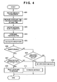
- FIG. 4 is a flowchart of a system embodying the present invention.
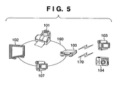
- FIG. 5 is a diagram illustrating the configuration of a system embodying the present invention.
- FIG. 6 is a flowchart of a system embodying the present invention.
- FIG. 7 is a diagram illustrating the configuration of a system embodying the present invention.
- FIG. 1 is a diagram illustrating the overall configuration of a system according to an embodiment of the present invention.
- a message relay device (information return device) 100, a printer 101, a digital television 102, a digital video camera 103A, and a digital camera 104A are connected to a network 150.
- a server 106 is connected to the message relay device 100 via a network 105.
- the message relay device 100 connects to the networks 105 and 150 and relays messages between the network 105 and the network 150.
- the abovementioned devices are used as examples, but the embodiment is not intended to be limited thereto.
- the abovementioned devices each have the necessary resources, such as processing functionality, data holding functionality, and so on needed in order to execute programs, and also have communication functionality for performing communication with control functionality, for controlling the apparatus (device) itself using the stated resources.
- FIG. 2 is a block diagram illustrating a general configuration of the hardware system of a device (apparatus), as given as an exemplary embodiment of the present invention. Note that the various apparatuses (devices) described herein are not intended to be limited to the configuration illustrated in FIG. 2 .
- 200 is an input/output bus (address bus, data bus, and control bus) for connecting various units to one another.
- 201 is a timer that has functionality for issuing an interrupt at specific intervals.
- the timer 201 also has what is known as watchdog timer functionality, time measurement functionality, and so on.
- 202 is a ROM (Read-Only Memory), and has functionality for storing program code, fixed data that does not change, and so on.
- 203 is a RAM (Random Access Memory) that functions as a main memory, and as an area for executed programs, an execution area for those programs, and a data area.
- 204 is a parallel controller, and has functionality for inputting/outputting parallel data handled within the computer from/to an external device as-is.
- 205 is a serial controller, and has functionality for outputting parallel data handled within the computer as serial data, and for converting serial data to parallel data and inputting the parallel data.
- 206 is an MPU (Microprocessor Unit), and has functionality for sequentially executing program commands and executing interrupts.
- MPU Microprocessor Unit
- 207 is a device controller, and has functionality for connecting general external input/output device such as hard disks, displays, and the like.
- 208 is a DMAC (Direct Memory Access Controller), and has functionality for executing control when data is exchanged directly between an internal memory and an external device.
- DMAC Direct Memory Access Controller
- 209 is an A/D (analog-to-digital) converter, and has functionality for converting analog data into digital data, digitizing amounts detected by a sensor or the like.
- 210 is a D/A (digital-to-analog) converter, and has functionality for converting digital data into analog data, digitizing an operational quantity for an external actuator or the like.
- the message relay device 100 has two network interfaces for connecting to the networks 150 and 105.
- the network interfaces 220 and 221 of the message relay device 100 send and receive messages via the networks 150 and 105.
- Devices aside from the message relay device 100 have a single network interface for connecting to either the network 150 or the network 105.
- FIG. 3 is a block diagram illustrating a module configuration of the message relay device (information return device) 100 given as an exemplary embodiment of the present invention.
- This module is a program module implemented by the MPU 206 executing a program stored in the ROM 202 shown in FIG. 2 .
- the program stored in the ROM 202 is a computer program read out by the MPU 206, which is a computer.
- the message relay device (information return device) 100 is configured of a message processing control unit 300, a message substitution unit 301, a communication condition ascertainment unit 302, a message relay unit 303, and a network IF (interface) 305.
- the message processing control unit 300 controls and exchanges data with the message substitution unit 301, the communication condition ascertainment unit 302, the message relay unit 303, and the network IFs 304, 305.
- the message substitution unit 301 determines whether or not to substitute processes performed by apparatuses connected to the network based on the error rate and the protocol type. When this substitution is to be performed, the message substitution unit 301 sends a response message in response to a message received from the network 150. In the present embodiment, the message substitution unit 301 sends a response message in response to a message received from the network 150. This response message is sent based on the error rates in the networks 150 and 105 and the time required for a response to be received from the device via the network 105. Furthermore, the message substitution unit 301 has functionality for emulating the protocol used by the device, in place of the device, and temporarily stores messages in regards to which processing cannot be emulated. In other words, the message substitution unit 301 obtains information via the network 105 (from the server 106).
- the communication condition ascertainment unit 302 has functionality for measuring the network error rate, functionality for measuring the response time after a message has been sent to an apparatus connected to the network, and functionality for determining the protocol type.
- the message relay unit 303 relays messages between the network 105 and the network 150. To be more specific, the message relay unit 303 sends, to the network 105, a message received via the network 150. Furthermore, the message relay unit 303 sends, to the network 150, a message received from the network 105 (the server 106) based on the communication conditions of the network 150 (and 105).
- a network IF 304 and the network IF 305 are network interfaces (NET/IF).
- the network IFs 304 and 305 have functionality for performing control so as to forward data between information processing devices via the networks 150 and 105, respectively, and functionality for diagnosing network conditions.
- the network IFs 304 and 305 have functionality for counting their respective numbers of outgoing packets, incoming packets, outgoing packet errors, incoming packet errors, and collision numbers.
- the network IFs 304 and 305 are connected to the networks 150 and 105, respectively, and receive/send messages via the networks 150 and 105, respectively.
- FIG. 4 illustrates part of the program stored in the ROM 202; this program is a computer program read out by the MPU 206, which is a computer.
- the message relay device (information return device) 100 emulates a digital media server compliant with the UPnP standard using the message substitution unit 301.
- the message relay device 100 then provides or uploads content from the server 106 to the printer 101, the digital television 102, the digital video camera 103A, and the digital camera 104A, which are UPnP-compliant devices.
- Step 401 the message substitution unit 301 of the message relay device (information return device) 100 obtains metadata of the content from the server 106 (that is, receives a message via the network 105). In other words, the message substitution unit 301 obtains information from the server 106 via the network 105. The message substitution unit 301 stores the obtained metadata.
- Step 402 the communication condition ascertainment unit 302 measures the time it takes to receive this response. Furthermore, in Step 402, the communication condition ascertainment unit 302 obtains the number of incoming/outgoing packets through the network IF 305 via the message processing control unit 300, the number of incoming/outgoing errors, and the number of collisions, and calculates the error rate.
- error rate ( Ierrs + Oerrs + Collis ) / ( Ipkts + Opkts ) * 100 (Ierrs: number of incoming packet errors; Oerrs: number of outgoing packet errors; Collis: number of collisions; Ipkts: number of incoming packets; Opkts: number of outgoing packets)
- the communication condition ascertainment unit 302 stores and holds the calculated error rate and the response time.
- the error rate is assumed to be 10%, and the response time 5 seconds.
- a UPnP-compliant device such as the digital television 102 or the like receives, for example, a request message sent for obtaining the content itself or metadata of the content (that is, receives a message via the network 150).
- Step 404 the communication condition ascertainment unit 302 determines the protocol (message).
- Step 405 the communication condition ascertainment unit 302 obtains the abovementioned information from the network IF 304, and calculates the error rate at that point in time using the abovementioned equation.
- Step 406 the message processing control unit 300 determines whether or not the protocol (message) determined in Step 404 can be substituted by the message substitution unit 301. If the protocol is substitutable, the procedure moves to Step 407, whereas if the protocol is unsubstitutable, the procedure moves to Step 408. For example, with a protocol that obtains the metadata of the content, the message substitution unit 301 obtains the metadata in advance, and thus it is determined that the protocol is substitutable; however, with a protocol that obtains the content itself, it is determined that the protocol is unsubstitutable. It should be noted that the determination in Step 406 is unnecessary when a protocol that is always substitutable is used, and thus the procedure moves to Step 407 after Step 405.
- Step 407 if the error rate calculated in Step 405 is higher than the error rate calculated in Step 402 (or, a reference value), the procedure moves to Step 409; if the error rate calculated in Step 405 is lower than the error rate calculated in Step 402 (or, the reference value), the procedure moves to Step 411.
- Step 409 the message substitution unit 301 does not forward the message received in Step 403 to the server 106, but rather makes a proxy response, as a result of it being determined that the protocol is substitutable, the error rate is high, and the response time exceeds the aforementioned 5 seconds.
- the metadata obtained in Step 401 is sent to the source from which the request message was sent.
- a proxy return is made in the case where the error rate is higher.
- the message substitution unit 301 sends a response message in response to a message received from the digital television 102 (a request message for obtaining the metadata of the content) based on the communication conditions of the networks 150 and 105.
- This response message includes the metadata obtained from the server 106 in Step 401.
- An example of the communication conditions of the networks 150 and 105 is the error rates in the networks 150 and 105 and the time required for a response to be received from the device (the server 106) via the network 105. Furthermore, upon receiving a request for obtaining the information (metadata) from the digital television 102 (Step 403), the message substitution unit 301 returns the information obtained in Step 401 based on the conditions at the time of the information being obtained in Step 401.
- Step 407 the criteria for determining whether or not to forward the message as described in Step 407 are not limited to the example given above. For example, (time limit until digital television 102 receives metadata (e.g. 30 seconds)) ⁇ (response time when message relay device 100 receives metadata from server 106 in Step 401 (in the above example, 5 seconds)) + (estimated round-trip time between digital television 102 and message relay device 100).
- (estimated round-trip time between digital television 102 and message relay device 100) (response time when message relay device 100 receives metadata from server 106 in Step 401) x (error rate when message relay device 100 receives request from digital television 102 in Step 403) / (error rate when message relay device 100 receives metadata from server 106 in Step 401).
- Step 411 the error rate in Step 407 is lower, and thus substitution is possible; therefore, it is determined that the chance of the response time exceeding 5 seconds is low.
- the message (metadata obtainment request message) is forwarded by the message relay unit 303 to the server 106 as-is.
- the server 106 upon receiving the message, the server 106 returns a response.
- the message relay unit 303 sends that response, via the network 150, to the source of the message received in Step 403.
- the message relay unit 303 sends, to the network 105 (the digital television 102), the message received from the network 150 (the server 106) based on the communication conditions of the network 150 (and 105).
- the message substitution unit 301 when the message substitution unit 301 has received a request for obtaining the information via the network 150 (from the digital television 102), the message substitution unit 301 newly obtains information in Step 411 and returns this obtained information based on the conditions at the time of the information being obtained in Step 401.
- Step 409 the request message is forwarded, and the saved information may be updated in preparation for the next request.
- the conditions when the message is received from the server 106 in Step 401 are good, it is determined that an appropriate response is to be returned to the source of the message in Step 403, even if the message received in Step 403 is sent to the network 105.
- the procedure then moves from Step 407 to Step 411. If the conditions are not good, the procedure moves from Step 407 to Step 409.
- the source of the message in Step 403 is the digital television 102.
- the conditions when the message is received from the server 106 being good refers to, for example, the quality of communication in the network 105 being good (e.g., when the response time is less than a predetermined value).
- Step 407 the message processing control unit 300 selects between sending the message received in Step 403 to the network 105 and sending a message to the network 150 in accordance with the message received in Step 401. In other words, in Step 407, the message processing control unit 300 selects between forwarding the message (Step 411) and making a proxy response (Step 409).
- the communication conditions of the network 150 as measured in Step 405 are good, it is determined that an appropriate response is to be returned to the source of the message in Step 403, even if the message received in Step 403 is sent to the network 105. Then, the message received via the network 150 is sent to the network 105. If the conditions are not good, the procedure moves from Step 407 to Step 409.
- the source of the message in Step 403 is the digital television 102.
- the communication conditions of the network 150 being good refers to, for example, the error rate of the message from the digital television 102 being no greater than a predetermined value.
- Step 407 the message processing control unit 300 selects between sending the message received in Step 403 to the network 105 and sending a message to the network 150 in accordance with the message received in Step 401. In other words, in Step 407, the message processing control unit 300 selects between forwarding the message and making a proxy response.
- the communication conditions of the network 105 as measured in Step 405 are good, it is determined that an appropriate response is to be returned to the source of the message in Step 403, even if the message received in Step 403 is sent to the network 105. Then, the message received via the network 150 is sent to the network 105. If the conditions are not good, the procedure moves from Step 407 to Step 409.
- the source of the message in Step 403 is the digital television 102.
- the conditions when the message is received from the server 106 being good refers to, for example, the quality of communication in the network 105 being good (e.g., when the response time is less than a predetermined value).
- Step 405 the communication condition ascertainment unit 302 sends a message to the server 106 and measures the amount of time it takes for a response thereto to return.
- Step 407 the message processing control unit 300 selects between sending the message received in Step 403 to the network 105 and sending a message to the network 150 in accordance with the message received in Step 401. In other words, in Step 407, the message processing control unit 300 selects between forwarding the message and making a proxy response.
- Step 408 if it has been determined in Step 406 that the protocol is unsubstitutable, the procedure moves to Step 411 in the case where the error rate calculated in Step 405 is lower than the error rate calculated in Step 402 (or, a reference value), whereas the procedure moves to Step 410 in the case where the error rate calculated in Step 405 is greater than the error rate calculated in Step 402.
- Step 411 the message relay unit 303 forwards the message received in Step 403 to the server 106 as-is, as a result of it being determined that the protocol is unsubstitutable, the error rate is low, and the chance of the response time exceeding the aforementioned 5 seconds is low.
- the message received in Step 403 is a content obtainment request message.
- Step 410 the protocol is unsubstitutable, the error rate is high, and thus the chance of the response time exceeding the aforementioned 5 seconds is high; therefore, the message substitution unit 301 returns an error message.
- the message substitution unit 301 sends an error message in response to the message received from the network 150, based on the communication conditions of the networks 150 and 105 and the protocol used by the message received from the digital television 102.
- the message substitution unit 301 selects between sending a message to the network 150 in accordance with the message received in Step 401 and sending an error message, based on the protocol used by the message received in Step 403.
- the message substitution unit 301 selects between making a proxy response (Step 409) and sending an error message to the network 150 (Step 410), based on the protocol used by the message received in Step 403.
- a response message is sent in accordance with a message received from the network 150, based on the communication conditions of the network 150. Therefore, if the communication conditions of the network 150 (or the network 105) are poor, and there is not enough time to forward a message to the server 106 via the network 105 and wait for a response from the server 106, a response message can be sent using the information obtained in Step 401.
- Step 403 when a request for obtaining the information has been received via the network 150 (Step 403), the information already obtained in Step 401 is returned, based on the conditions at the time of the information being obtained in Step 401. Therefore, if it takes too much time when the information is obtained from the server 106 via the network 105, and there is not enough time to newly obtain information from the server 106 via the network 105, the already-obtained information can be returned. If, however, it has not taken too much time when the information is obtained from the server 106 via the network 105, there is enough time to newly obtain information from the server 106 via the network 105, and thus the newly-obtained information can be returned.
- the communication conditions of the network 105 are examined, and a selection may be made between returning the information already obtained in Step 401 and newly obtaining information from the server 106.
- the conditions of the network 105 when receiving a request to obtain information via the network 150 can be determined based on the response time of a request, the request being sent to the server 106 when the request to obtain the information has been received via the network 150.
- Step 409 the request message is forwarded, and the saved information is updated in preparation for the next request.
- FIG. 5 is a diagram illustrating the configuration of the system according to the first variation of the present invention.
- the message relay device 100 is assumed to have wireless LAN access point functionality.
- the printer 101, the digital television 102, and a digital video camera 107 are connected to the message relay device 100 via a wired network 160 using, for example, Ethernet®. Furthermore, a digital video camera 103 and a digital camera 104 are connected to the message relay device 100 via a wireless network 170 using, for example, IEEE 802.11a/b/g/n.
- the message relay device 100 connects to the networks 160 and 170 and relays messages between the wired network 160 and the wireless network 170.
- Bridge and router functions can serve as the wireless LAN access point functionality of the message relay device 100; however, the present variation can be realized using both functions, and is not intended to be limited to either one.
- the configuration of the hardware system of the device is the same as that shown in FIG. 2
- the module configuration of the message relay device 100 is the same as that shown in FIG. 3 .
- the network IFs 304 and 305 are connected to the wired network 160 and the wireless network 170, respectively.
- FIG. 6 illustrates part of the program stored in the ROM 202; this program is a computer program read out by the MPU 206, which is a computer.
- the UPnP protocol shall be used as an example.
- a UPnP protocol message is substituted by the message substitution unit 301 of the message relay device 100.
- content is circulated and control performed among the printer 101, the digital television 102, the digital video camera 103, and the digital camera 104, which are UPnP-compliant devices.
- the UPnP protocol is described here as an example, the present invention is not intended to be limited to this protocol.
- Step 601 the message substitution unit 301 sends an SSDP device search message to the wireless network 170.
- SSDP Simple Service Discovery Protocol
- the message substitution unit 301 receives a response message, and stores the details of the received response message.
- the communication condition ascertainment unit 302 measures the time it takes to receive the response, and at the same time measures the radio field intensity (Received Signal Strength Indicator, or RSSI).
- the communication condition ascertainment unit 302 stores and holds the obtained radio field intensity and the response time. For example, it is assumed that the radio field intensity is 80 and the response time is 1 second.
- the UPnP-compliant devices such as the digital television 102, send, for example, an SSDP device search message.
- the SSDP device search message is received by the network IF 304, and in Step 604, the communication condition ascertainment unit 302 determines the protocol (message).
- the communication condition ascertainment unit 302 obtains the radio field intensity at that point in time.
- Step 606 the message processing control unit 300 determines whether or not the protocol determined in Step 604 is substitutable by the message substitution unit 301. If the protocol is substitutable, the procedure moves to Step 607, whereas if the protocol is unsubstitutable, the procedure moves to Step 608.
- an SSDP protocol is substitutable because device information can be obtained from the UPnP-compliant device connected to the wireless network in advance.
- Device description and service description obtainment protocols are also substitutable for the same reason. If the information requested by the message received in Step 603 has already been received in Step 602, the message substitution unit 301 determines that the protocol is substitutable. However, because the control protocol of the device is a message that actually controls the UPnP-compliant device, the message substitution unit 301 determines that the protocol is unsubstitutable.
- Step 606 is unnecessary when a protocol that is always substitutable is used, and thus the procedure moves to Step 607 after Step 605.
- Step 607 the procedure moves to Step 609 in the case where the radio field intensity obtained in Step 605 is less than the radio field intensity obtained in Step 602 (or a reference value), whereas the procedure moves to Step 610 in the case where the radio field intensity obtained in Step 605 is greater than the radio field intensity obtained in Step 602.
- the comparison made in Step 607 is performed based on, for example, the radio field intensities described hereinafter; that is, the lower of the radio field intensities of the digital video camera 103 and the digital camera 104 as measured in Step 602, and the lower of the radio field intensities of the digital video camera 103 and the digital camera 104 as measured in Step 605, are compared.
- Steps 602 and 605 the radio field intensity of noise (disturbing waves) aside from the signal sent from the digital video camera 103 and the digital camera 104 may be measured and used in the comparison in Step 607. However, in such a case, if the radio field intensity obtained in Step 605 is greater, the procedure moves to Step 609.
- the message substitution unit 301 does not forward the device search message received in Step 603, as a result of it being determined that the protocol determined in Step 604 is substitutable, the radio field intensity is low, and the response time significantly exceeds the aforementioned 1 second.
- the message substitution unit 301 makes a proxy response instead.
- the message substitution unit 301 sends a message including the details of the message received in Step 602 to the source of the message received in Step 603.
- the message substitution unit 301 sends a response message in response to the message received from the wired network 160 (the digital television 102) based on the communication conditions of the networks 160 and 170.
- Step 610 substitution is possible, and furthermore, the radio field intensity in Step 607 is greater; therefore, it is determined that the chance of the response time being higher than the aforementioned 1 second is low.
- the message (device search message) is forwarded by the message relay unit 303 to the wireless network 170 as-is.
- the digital video camera 103 and the digital camera 104 which are connected to the wireless network 170, return a response.
- the message relay unit 303 sends that response, via the wired network 160, to the source of the message received in Step 603.
- the message relay unit 303 sends, to the wired network 160(the digital television 102), the message received from the wireless network 170, based on the communication conditions of the networks 160 and 170.
- Step 609 the message is forwarded, and the saved information may be updated in preparation for the next search message.
- Step 602 if the conditions when the message is received from the wireless network 170 in Step 602 are good, it is determined that an appropriate response is to be returned to the source of the message, even if the message received in Step 603 is sent to the wireless network 170.
- the procedure then moves from Step 607 to Step 610. If the conditions are not good, the procedure moves from Step 607 to Step 609.
- the source of the message (Step 603) is, for example, the digital television 102.
- the conditions when the message is received from the wireless network 170 being good refers to, for example, the quality of communication in the wireless network 170 being good.
- Step 607 the message processing control unit 300 selects between sending the message received in Step 603 to the wireless network 170 and sending a message to the wired network 160 in accordance with the message received in Step 602. In other words, in Step 607, the message processing control unit 300 selects between forwarding the message and making a proxy response.
- Step 608 if it has been determined in Step 606 that the protocol is unsubstitutable, the procedure moves to Step 610 in the case where the radio field intensity obtained in Step 605 is greater than the radio field intensity obtained in Step 602, whereas the procedure moves to Step 611 in the case where the radio field intensity obtained in Step 605 is lower than the radio field intensity obtained in Step 602.
- the protocol is unsubstitutable and the radio field intensity is less, and thus the chance of the response time significantly exceeding the aforementioned 1 second is high; therefore, the message substitution unit 301 returns an error message.
- the message substitution unit 301 sends an error message in response to the message received from the wired network 160, based on the communication conditions of the networks 160 and 170 and the protocol used by the message received from the digital television 102.
- the message substitution unit 301 selects between sending a message to the wired network 160 in accordance with the message received in Step 602 and sending an error message, based on the protocol used by the message received from the wired network 160.
- the message substitution unit 301 selects between making a proxy response (Step 609) and returning an error message to the network 160 (Step 611), based on the protocol used by the message received from the wired network 160.
- FIG. 7 is a diagram illustrating the configuration of the system according to the second variation of the present invention.
- the message relay device 100 is assumed to have Virtual Private Network (VPN) functionality.
- VPN Virtual Private Network
- the printer 101 and the digital television 102 are connected to the message relay device 100 via a network 180. Furthermore, the digital video camera 103 and the digital camera 104 are connected to a message relay device 108, which has the same functionality as the message relay device 100, via a network 190. The message relay device 100 and the message relay device 108 are connected to one another via VPN on a network 140.
- the configuration of the hardware system of the device is the same as that shown in FIG. 2
- the module configurations of the message relay devices 100 and 108 are the same as that shown in FIG. 3 .
- the network IFs 304 and 305 are connected to the network 140.
- the UPnP protocol is taken as an example, and a UPnP protocol message is substituted by the message substitution unit 301 of the message relay devices 100 and 108. Furthermore, it is assumed that content is circulated and control performed among the printer 101, the digital television 102, the digital video camera 103, and the digital camera 104, which are UPnP-compliant devices. However, although the UPnP protocol is described here as an example, the present invention is not intended to be limited to this protocol.
- the message substitution unit 301 of the message relay device 100 obtains and holds device information of the printer 101 and the digital television 102, which are UPnP-compliant devices connected to the network 180.
- the message substitution unit 301 of the message relay device 108 obtains and holds device information of the digital video camera 103 and the digital camera 104, which are UPnP-compliant devices connected to the network 190.
- the message relay devices 100 and 108 exchange device information they hold with one another using the respective message substitution units 301.
- the message substitution unit 301 of the message relay device 100 connected to the network 180 can perform substitution for the UPnP-compliant devices connected to the network 190. Furthermore, the message substitution unit 301 of the message relay device 108 connected to the network 190 can perform substitution for the UPnP-compliant devices connected to the network 180.
- message substitution is carried out by the message relay device 100 and the message relay device 108, respectively.
- the processing flow thereof is the same as that shown in FIG. 4 .
Landscapes
- Engineering & Computer Science (AREA)
- Computer Networks & Wireless Communication (AREA)
- Signal Processing (AREA)
- Automation & Control Theory (AREA)
- Computing Systems (AREA)
- Quality & Reliability (AREA)
- Small-Scale Networks (AREA)
- Data Exchanges In Wide-Area Networks (AREA)
- Communication Control (AREA)
Abstract
Description
- The present invention relates to a relay apparatus, a relay method, and a computer program that receives a first request via a network and sends a second request to a different network in response to the first request.
- Bridges, routers, gateways, and wireless access points are examples of devices that connect plural distributed networks to one another.
- These devices block forwarding based on the destination address, protocol, and so on of a transmitted message, or control the priority of a transmitted message based on the type of network from which the transmitted message was sent, the protocol of the transmitted message, and the like. A gateway also performs congestion control and network protocol conversion of transmitted data.
- Conventionally, whether to pass on a transmitted message or discard the transmitted message is determined based on the IP address or MAC address of the transmitted data according to Internet Protocol (IP) or based on the type of network protocol.
- Furthermore, with the IP and TCP protocols, when a congestion control function is to be implemented by a gateway that has detected a state of congestion or by a computer or home electric appliance connected to the network, the congestion is suppressed in the following manner. First, a request (ICMP source quench) is sent to the computer, home electric appliance, or the like that has sent the transmitted message that is causing the congested state, requesting the computer or appliance to reduce its sending speed. Then, having received this request, the computer or home electric appliance suppresses the congestion by reducing the speed at which the transmission message is being sent, up until the request is no longer received.
- For example, in the system for data filtering between transmission paths disclosed in Japanese Patent Laid-Open No.
07-210473 - However, there is a problem in that even if control is executed on the TCP or UDP/IP levels while in a congested state, and the congestion is suppressed on such a level, such control may lead to error cases under the rules of an upper protocol, or may violate the rules of that upper protocol. For example, if the upper protocol has a rule in which when a message is sent to a certain end point, the response thereto must be executed within a certain number of seconds, and an error is defined for when the response is not executed within the certain number of seconds, such a situation results in an error case. If not defined as an error, this is nevertheless a violation of the rules of the protocol.
- There is another problem that arises when controlling the priority of transmitted messages in mid-network using the protocol type: in a transmission path where various messages are transmitted, although the chance of a specific message being transmitted correctly improves, the chance of arrival for that message cannot be guaranteed.
- Furthermore, another problem arises when one of the networks connected to the bridge, router, gateway, or wireless access point becomes incapable of communications: the messages flowing through that network do not arrive at their destinations, and thus the upper protocol does not function.
- The present invention provides a relay apparatus, a relay method, and a computer program to respond to a request received via a network in a short amount of time.
- The present invention in its first aspect provides a relay apparatus as specified in claims 1 to 8.
- The present invention in its second aspect provides a relay method as specified in claims 9 to 16.
- The present invention in its third aspect provides a computer program as specified in claims 17 to 21.
- Further features of the present invention will become apparent from the following description of exemplary embodiments (with reference to the attached drawings).
-
FIG. 1 is a diagram illustrating the configuration of a system embodying the present invention. -
FIG. 2 is a block diagram illustrating an apparatus system embodying the present invention. -
FIG. 3 is a diagram illustrating a module configuration of a message relay device embodying the present invention. -
FIG. 4 is a flowchart of a system embodying the present invention. -
FIG. 5 is a diagram illustrating the configuration of a system embodying the present invention. -
FIG. 6 is a flowchart of a system embodying the present invention. -
FIG. 7 is a diagram illustrating the configuration of a system embodying the present invention. - An embodiment of the present invention shall be described hereinafter with reference to the drawings. Although specific examples of processes are denoted herein, the present invention is not intended to be limited to these specific examples of processes.
-
FIG. 1 is a diagram illustrating the overall configuration of a system according to an embodiment of the present invention. - As can be seen in
FIG. 1 , a message relay device (information return device) 100, aprinter 101, adigital television 102, adigital video camera 103A, and adigital camera 104A are connected to anetwork 150. Furthermore, aserver 106 is connected to themessage relay device 100 via anetwork 105. Themessage relay device 100 connects to thenetworks network 105 and thenetwork 150. In the present embodiment, the abovementioned devices (apparatuses) are used as examples, but the embodiment is not intended to be limited thereto. The abovementioned devices each have the necessary resources, such as processing functionality, data holding functionality, and so on needed in order to execute programs, and also have communication functionality for performing communication with control functionality, for controlling the apparatus (device) itself using the stated resources. -
FIG. 2 is a block diagram illustrating a general configuration of the hardware system of a device (apparatus), as given as an exemplary embodiment of the present invention. Note that the various apparatuses (devices) described herein are not intended to be limited to the configuration illustrated inFIG. 2 . - 200 is an input/output bus (address bus, data bus, and control bus) for connecting various units to one another. 201 is a timer that has functionality for issuing an interrupt at specific intervals. The
timer 201 also has what is known as watchdog timer functionality, time measurement functionality, and so on. - 202 is a ROM (Read-Only Memory), and has functionality for storing program code, fixed data that does not change, and so on. 203 is a RAM (Random Access Memory) that functions as a main memory, and as an area for executed programs, an execution area for those programs, and a data area.
- 204 is a parallel controller, and has functionality for inputting/outputting parallel data handled within the computer from/to an external device as-is. 205 is a serial controller, and has functionality for outputting parallel data handled within the computer as serial data, and for converting serial data to parallel data and inputting the parallel data.
- 206 is an MPU (Microprocessor Unit), and has functionality for sequentially executing program commands and executing interrupts.
- 207 is a device controller, and has functionality for connecting general external input/output device such as hard disks, displays, and the like. 208 is a DMAC (Direct Memory Access Controller), and has functionality for executing control when data is exchanged directly between an internal memory and an external device.
- 209 is an A/D (analog-to-digital) converter, and has functionality for converting analog data into digital data, digitizing amounts detected by a sensor or the like. 210 is a D/A (digital-to-analog) converter, and has functionality for converting digital data into analog data, digitizing an operational quantity for an external actuator or the like.
- 220 and 221 are network interfaces (NET/IF). The
message relay device 100 has two network interfaces for connecting to thenetworks network interfaces message relay device 100 send and receive messages via thenetworks message relay device 100 have a single network interface for connecting to either thenetwork 150 or thenetwork 105. -
FIG. 3 is a block diagram illustrating a module configuration of the message relay device (information return device) 100 given as an exemplary embodiment of the present invention. This module is a program module implemented by the MPU 206 executing a program stored in theROM 202 shown inFIG. 2 . The program stored in theROM 202 is a computer program read out by the MPU 206, which is a computer. - The message relay device (information return device) 100 is configured of a message
processing control unit 300, amessage substitution unit 301, a communicationcondition ascertainment unit 302, amessage relay unit 303, and a network IF (interface) 305. - The message
processing control unit 300 controls and exchanges data with themessage substitution unit 301, the communicationcondition ascertainment unit 302, themessage relay unit 303, and thenetwork IFs - The
message substitution unit 301 determines whether or not to substitute processes performed by apparatuses connected to the network based on the error rate and the protocol type. When this substitution is to be performed, themessage substitution unit 301 sends a response message in response to a message received from thenetwork 150. In the present embodiment, themessage substitution unit 301 sends a response message in response to a message received from thenetwork 150. This response message is sent based on the error rates in thenetworks network 105. Furthermore, themessage substitution unit 301 has functionality for emulating the protocol used by the device, in place of the device, and temporarily stores messages in regards to which processing cannot be emulated. In other words, themessage substitution unit 301 obtains information via the network 105 (from the server 106). - The communication
condition ascertainment unit 302 has functionality for measuring the network error rate, functionality for measuring the response time after a message has been sent to an apparatus connected to the network, and functionality for determining the protocol type. - The
message relay unit 303 relays messages between thenetwork 105 and thenetwork 150. To be more specific, themessage relay unit 303 sends, to thenetwork 105, a message received via thenetwork 150. Furthermore, themessage relay unit 303 sends, to thenetwork 150, a message received from the network 105 (the server 106) based on the communication conditions of the network 150 (and 105). - A network IF 304 and the network IF 305 are network interfaces (NET/IF). The
network IFs networks network IFs network IFs networks networks - The flow of the overall process performed by the system embodying the present invention shall be described with reference to
FIG. 4. FIG. 4 illustrates part of the program stored in theROM 202; this program is a computer program read out by theMPU 206, which is a computer. - The following descriptions shall be given using the UPnP protocol as an example. That is, the message relay device (information return device) 100 emulates a digital media server compliant with the UPnP standard using the
message substitution unit 301. Themessage relay device 100 then provides or uploads content from theserver 106 to theprinter 101, thedigital television 102, thedigital video camera 103A, and thedigital camera 104A, which are UPnP-compliant devices. - Although the UPnP protocol is used as an example here for the sake of clarity, the present invention is not intended to be limited to this protocol.
- In
Step 401, themessage substitution unit 301 of the message relay device (information return device) 100 obtains metadata of the content from the server 106 (that is, receives a message via the network 105). In other words, themessage substitution unit 301 obtains information from theserver 106 via thenetwork 105. Themessage substitution unit 301 stores the obtained metadata. - In
Step 402, the communicationcondition ascertainment unit 302 measures the time it takes to receive this response. Furthermore, inStep 402, the communicationcondition ascertainment unit 302 obtains the number of incoming/outgoing packets through the network IF 305 via the messageprocessing control unit 300, the number of incoming/outgoing errors, and the number of collisions, and calculates the error rate. - The equation used for this calculation is as follows:

(Ierrs: number of incoming packet errors; Oerrs: number of outgoing packet errors; Collis: number of collisions; Ipkts: number of incoming packets; Opkts: number of outgoing packets)
Here, the communicationcondition ascertainment unit 302 stores and holds the calculated error rate and the response time. As an example, the error rate is assumed to be 10%, and the response time 5 seconds. - In
Step 403, a UPnP-compliant device such as thedigital television 102 or the like receives, for example, a request message sent for obtaining the content itself or metadata of the content (that is, receives a message via the network 150). - In
Step 404, the communicationcondition ascertainment unit 302 determines the protocol (message). - In
Step 405, the communicationcondition ascertainment unit 302 obtains the abovementioned information from the network IF 304, and calculates the error rate at that point in time using the abovementioned equation. - In
Step 406, the messageprocessing control unit 300 determines whether or not the protocol (message) determined inStep 404 can be substituted by themessage substitution unit 301. If the protocol is substitutable, the procedure moves to Step 407, whereas if the protocol is unsubstitutable, the procedure moves to Step 408. For example, with a protocol that obtains the metadata of the content, themessage substitution unit 301 obtains the metadata in advance, and thus it is determined that the protocol is substitutable; however, with a protocol that obtains the content itself, it is determined that the protocol is unsubstitutable. It should be noted that the determination inStep 406 is unnecessary when a protocol that is always substitutable is used, and thus the procedure moves to Step 407 afterStep 405. - Furthermore, while the abovementioned determination is executed in the present embodiment, there are various criteria for determination depending on the protocol, and thus the present embodiment is not limited hereto.
- In
Step 407, if the error rate calculated inStep 405 is higher than the error rate calculated in Step 402 (or, a reference value), the procedure moves to Step 409; if the error rate calculated inStep 405 is lower than the error rate calculated in Step 402 (or, the reference value), the procedure moves to Step 411. - In
Step 409, themessage substitution unit 301 does not forward the message received inStep 403 to theserver 106, but rather makes a proxy response, as a result of it being determined that the protocol is substitutable, the error rate is high, and the response time exceeds the aforementioned 5 seconds. In other words, the metadata obtained inStep 401 is sent to the source from which the request message was sent. Here, a proxy return is made in the case where the error rate is higher. Furthermore, inStep 409, themessage substitution unit 301 sends a response message in response to a message received from the digital television 102 (a request message for obtaining the metadata of the content) based on the communication conditions of thenetworks server 106 inStep 401. An example of the communication conditions of thenetworks networks network 105. Furthermore, upon receiving a request for obtaining the information (metadata) from the digital television 102 (Step 403), themessage substitution unit 301 returns the information obtained inStep 401 based on the conditions at the time of the information being obtained inStep 401. - Note that the criteria for determining whether or not to forward the message as described in
Step 407 are not limited to the example given above. For example, (time limit untildigital television 102 receives metadata (e.g. 30 seconds)) ≥ (response time whenmessage relay device 100 receives metadata fromserver 106 in Step 401 (in the above example, 5 seconds)) + (estimated round-trip time betweendigital television 102 and message relay device 100). - However, (estimated round-trip time between
digital television 102 and message relay device 100) = (response time whenmessage relay device 100 receives metadata fromserver 106 in Step 401) x (error rate whenmessage relay device 100 receives request fromdigital television 102 in Step 403) / (error rate whenmessage relay device 100 receives metadata fromserver 106 in Step 401). - In
Step 411, the error rate inStep 407 is lower, and thus substitution is possible; therefore, it is determined that the chance of the response time exceeding 5 seconds is low. As a result, the message (metadata obtainment request message) is forwarded by themessage relay unit 303 to theserver 106 as-is. Then, upon receiving the message, theserver 106 returns a response. Themessage relay unit 303 sends that response, via thenetwork 150, to the source of the message received inStep 403. In other words, themessage relay unit 303 sends, to the network 105 (the digital television 102), the message received from the network 150 (the server 106) based on the communication conditions of the network 150 (and 105). To put it differently, when themessage substitution unit 301 has received a request for obtaining the information via the network 150 (from the digital television 102), themessage substitution unit 301 newly obtains information inStep 411 and returns this obtained information based on the conditions at the time of the information being obtained inStep 401. - Note that in the case where a proxy response is made is
Step 409, the request message is forwarded, and the saved information may be updated in preparation for the next request. - According to another configuration, if the conditions when the message is received from the
server 106 inStep 401 are good, it is determined that an appropriate response is to be returned to the source of the message inStep 403, even if the message received inStep 403 is sent to thenetwork 105. The procedure then moves fromStep 407 to Step 411. If the conditions are not good, the procedure moves fromStep 407 to Step 409. Here, the source of the message inStep 403 is thedigital television 102. Moreover, the conditions when the message is received from theserver 106 being good refers to, for example, the quality of communication in thenetwork 105 being good (e.g., when the response time is less than a predetermined value). InStep 407, the messageprocessing control unit 300 selects between sending the message received inStep 403 to thenetwork 105 and sending a message to thenetwork 150 in accordance with the message received inStep 401. In other words, inStep 407, the messageprocessing control unit 300 selects between forwarding the message (Step 411) and making a proxy response (Step 409). - According to yet another configuration, if the communication conditions of the
network 150 as measured inStep 405 are good, it is determined that an appropriate response is to be returned to the source of the message inStep 403, even if the message received inStep 403 is sent to thenetwork 105. Then, the message received via thenetwork 150 is sent to thenetwork 105. If the conditions are not good, the procedure moves fromStep 407 to Step 409. Here, the source of the message inStep 403 is thedigital television 102. Moreover, the communication conditions of thenetwork 150 being good refers to, for example, the error rate of the message from thedigital television 102 being no greater than a predetermined value. InStep 407, the messageprocessing control unit 300 selects between sending the message received inStep 403 to thenetwork 105 and sending a message to thenetwork 150 in accordance with the message received inStep 401. In other words, inStep 407, the messageprocessing control unit 300 selects between forwarding the message and making a proxy response. - According to yet another configuration, if the communication conditions of the
network 105 as measured inStep 405 are good, it is determined that an appropriate response is to be returned to the source of the message inStep 403, even if the message received inStep 403 is sent to thenetwork 105. Then, the message received via thenetwork 150 is sent to thenetwork 105. If the conditions are not good, the procedure moves fromStep 407 to Step 409. Here, the source of the message inStep 403 is thedigital television 102. Moreover, the conditions when the message is received from theserver 106 being good refers to, for example, the quality of communication in thenetwork 105 being good (e.g., when the response time is less than a predetermined value). In order to determine the quality of communication in thenetwork 105, inStep 405, the communicationcondition ascertainment unit 302 sends a message to theserver 106 and measures the amount of time it takes for a response thereto to return. InStep 407, the messageprocessing control unit 300 selects between sending the message received inStep 403 to thenetwork 105 and sending a message to thenetwork 150 in accordance with the message received inStep 401. In other words, inStep 407, the messageprocessing control unit 300 selects between forwarding the message and making a proxy response. - In
Step 408, if it has been determined inStep 406 that the protocol is unsubstitutable, the procedure moves to Step 411 in the case where the error rate calculated inStep 405 is lower than the error rate calculated in Step 402 (or, a reference value), whereas the procedure moves to Step 410 in the case where the error rate calculated inStep 405 is greater than the error rate calculated inStep 402. - In
Step 411, themessage relay unit 303 forwards the message received inStep 403 to theserver 106 as-is, as a result of it being determined that the protocol is unsubstitutable, the error rate is low, and the chance of the response time exceeding the aforementioned 5 seconds is low. Here, the message received inStep 403 is a content obtainment request message. - In
Step 410, the protocol is unsubstitutable, the error rate is high, and thus the chance of the response time exceeding the aforementioned 5 seconds is high; therefore, themessage substitution unit 301 returns an error message. In other words, themessage substitution unit 301 sends an error message in response to the message received from thenetwork 150, based on the communication conditions of thenetworks digital television 102. Furthermore, themessage substitution unit 301 selects between sending a message to thenetwork 150 in accordance with the message received inStep 401 and sending an error message, based on the protocol used by the message received inStep 403. Alternatively, themessage substitution unit 301 selects between making a proxy response (Step 409) and sending an error message to the network 150 (Step 410), based on the protocol used by the message received inStep 403. - In the present embodiment, a response message is sent in accordance with a message received from the
network 150, based on the communication conditions of thenetwork 150. Therefore, if the communication conditions of the network 150 (or the network 105) are poor, and there is not enough time to forward a message to theserver 106 via thenetwork 105 and wait for a response from theserver 106, a response message can be sent using the information obtained inStep 401. - In addition, when a request for obtaining the information has been received via the network 150 (Step 403), the information already obtained in
Step 401 is returned, based on the conditions at the time of the information being obtained inStep 401. Therefore, if it takes too much time when the information is obtained from theserver 106 via thenetwork 105, and there is not enough time to newly obtain information from theserver 106 via thenetwork 105, the already-obtained information can be returned. If, however, it has not taken too much time when the information is obtained from theserver 106 via thenetwork 105, there is enough time to newly obtain information from theserver 106 via thenetwork 105, and thus the newly-obtained information can be returned. In addition, when a request for obtaining the information has been received via thenetwork 150, the communication conditions of thenetwork 105 are examined, and a selection may be made between returning the information already obtained inStep 401 and newly obtaining information from theserver 106. The conditions of thenetwork 105 when receiving a request to obtain information via thenetwork 150 can be determined based on the response time of a request, the request being sent to theserver 106 when the request to obtain the information has been received via thenetwork 150. - Note that in the case where a proxy response is made is
Step 409, the request message is forwarded, and the saved information is updated in preparation for the next request. - Descriptions of a system according to a first variation of the present invention shall be given hereinafter with reference to
FIG. 5 . -
FIG. 5 is a diagram illustrating the configuration of the system according to the first variation of the present invention. Here, themessage relay device 100 is assumed to have wireless LAN access point functionality. - The
printer 101, thedigital television 102, and adigital video camera 107 are connected to themessage relay device 100 via awired network 160 using, for example, Ethernet®. Furthermore, adigital video camera 103 and adigital camera 104 are connected to themessage relay device 100 via awireless network 170 using, for example, IEEE 802.11a/b/g/n. Themessage relay device 100 connects to thenetworks wired network 160 and thewireless network 170. - Bridge and router functions can serve as the wireless LAN access point functionality of the
message relay device 100; however, the present variation can be realized using both functions, and is not intended to be limited to either one. - Note that the configuration of the hardware system of the device (apparatus) is the same as that shown in
FIG. 2 , and the module configuration of themessage relay device 100 is the same as that shown inFIG. 3 . However, thenetwork IFs wired network 160 and thewireless network 170, respectively. - The flow of the overall process performed by the system according to the first variation of the present invention shall be described with reference to
FIG. 6. FIG. 6 illustrates part of the program stored in theROM 202; this program is a computer program read out by theMPU 206, which is a computer. - Here, the UPnP protocol shall be used as an example. A UPnP protocol message is substituted by the
message substitution unit 301 of themessage relay device 100. Furthermore, it is assumed that content is circulated and control performed among theprinter 101, thedigital television 102, thedigital video camera 103, and thedigital camera 104, which are UPnP-compliant devices. However, although the UPnP protocol is described here as an example, the present invention is not intended to be limited to this protocol. - In
Step 601, themessage substitution unit 301 sends an SSDP device search message to thewireless network 170. Here, "SSDP" is anagram of Simple Service Discovery Protocol, and is a protocol for searching and discovering UPnP devices present on a network. Next, themessage substitution unit 301 receives a response message, and stores the details of the received response message. - In
Step 602, the communicationcondition ascertainment unit 302 measures the time it takes to receive the response, and at the same time measures the radio field intensity (Received Signal Strength Indicator, or RSSI). Here, the communicationcondition ascertainment unit 302 stores and holds the obtained radio field intensity and the response time. For example, it is assumed that the radio field intensity is 80 and the response time is 1 second. - The UPnP-compliant devices, such as the
digital television 102, send, for example, an SSDP device search message. InStep 603, the SSDP device search message is received by the network IF 304, and inStep 604, the communicationcondition ascertainment unit 302 determines the protocol (message). InStep 605, the communicationcondition ascertainment unit 302 obtains the radio field intensity at that point in time. - In
Step 606, the messageprocessing control unit 300 determines whether or not the protocol determined inStep 604 is substitutable by themessage substitution unit 301. If the protocol is substitutable, the procedure moves to Step 607, whereas if the protocol is unsubstitutable, the procedure moves to Step 608. - For example, an SSDP protocol is substitutable because device information can be obtained from the UPnP-compliant device connected to the wireless network in advance. Device description and service description obtainment protocols are also substitutable for the same reason. If the information requested by the message received in
Step 603 has already been received inStep 602, themessage substitution unit 301 determines that the protocol is substitutable. However, because the control protocol of the device is a message that actually controls the UPnP-compliant device, themessage substitution unit 301 determines that the protocol is unsubstitutable. - Note that, while the abovementioned determination is executed in the present embodiment; there are various criteria for determination depending on the protocol, and thus the determination is not intended to be limited to the descriptions provided here. Furthermore, the determination in
Step 606 is unnecessary when a protocol that is always substitutable is used, and thus the procedure moves to Step 607 afterStep 605. - In
Step 607, the procedure moves to Step 609 in the case where the radio field intensity obtained inStep 605 is less than the radio field intensity obtained in Step 602 (or a reference value), whereas the procedure moves to Step 610 in the case where the radio field intensity obtained inStep 605 is greater than the radio field intensity obtained inStep 602. Here, the comparison made inStep 607 is performed based on, for example, the radio field intensities described hereinafter; that is, the lower of the radio field intensities of thedigital video camera 103 and thedigital camera 104 as measured inStep 602, and the lower of the radio field intensities of thedigital video camera 103 and thedigital camera 104 as measured inStep 605, are compared. Alternatively, inSteps digital video camera 103 and thedigital camera 104 may be measured and used in the comparison inStep 607. However, in such a case, if the radio field intensity obtained inStep 605 is greater, the procedure moves to Step 609. - In
Step 609, themessage substitution unit 301 does not forward the device search message received inStep 603, as a result of it being determined that the protocol determined inStep 604 is substitutable, the radio field intensity is low, and the response time significantly exceeds the aforementioned 1 second. Themessage substitution unit 301 makes a proxy response instead. In other words, themessage substitution unit 301 sends a message including the details of the message received inStep 602 to the source of the message received inStep 603. Themessage substitution unit 301 sends a response message in response to the message received from the wired network 160 (the digital television 102) based on the communication conditions of thenetworks - In
Step 610, substitution is possible, and furthermore, the radio field intensity inStep 607 is greater; therefore, it is determined that the chance of the response time being higher than the aforementioned 1 second is low. As a result, the message (device search message) is forwarded by themessage relay unit 303 to thewireless network 170 as-is. Upon receiving the message, thedigital video camera 103 and thedigital camera 104, which are connected to thewireless network 170, return a response. Themessage relay unit 303 sends that response, via thewired network 160, to the source of the message received inStep 603. In other words, themessage relay unit 303 sends, to the wired network 160(the digital television 102), the message received from thewireless network 170, based on the communication conditions of thenetworks - Note that in the case where a proxy response is made is
Step 609, the message is forwarded, and the saved information may be updated in preparation for the next search message. - According to another configuration, if the conditions when the message is received from the
wireless network 170 inStep 602 are good, it is determined that an appropriate response is to be returned to the source of the message, even if the message received inStep 603 is sent to thewireless network 170. The procedure then moves fromStep 607 to Step 610. If the conditions are not good, the procedure moves fromStep 607 to Step 609. Here, the source of the message (Step 603) is, for example, thedigital television 102. The conditions when the message is received from thewireless network 170 being good refers to, for example, the quality of communication in thewireless network 170 being good. Specifically, this refers to the radio field intensity from thedigital video camera 103, thedigital camera 104, and so on being stronger than a predetermined value, or the radio field intensity of noise being weaker than a predetermined value. InStep 607, the messageprocessing control unit 300 selects between sending the message received inStep 603 to thewireless network 170 and sending a message to thewired network 160 in accordance with the message received inStep 602. In other words, inStep 607, the messageprocessing control unit 300 selects between forwarding the message and making a proxy response. - In
Step 608, if it has been determined inStep 606 that the protocol is unsubstitutable, the procedure moves to Step 610 in the case where the radio field intensity obtained inStep 605 is greater than the radio field intensity obtained inStep 602, whereas the procedure moves to Step 611 in the case where the radio field intensity obtained inStep 605 is lower than the radio field intensity obtained inStep 602. - In
Step 611, the protocol is unsubstitutable and the radio field intensity is less, and thus the chance of the response time significantly exceeding the aforementioned 1 second is high; therefore, themessage substitution unit 301 returns an error message. Themessage substitution unit 301 sends an error message in response to the message received from the wirednetwork 160, based on the communication conditions of thenetworks digital television 102. In other words, themessage substitution unit 301 selects between sending a message to thewired network 160 in accordance with the message received inStep 602 and sending an error message, based on the protocol used by the message received from the wirednetwork 160. To rephrase, themessage substitution unit 301 selects between making a proxy response (Step 609) and returning an error message to the network 160 (Step 611), based on the protocol used by the message received from the wirednetwork 160. - Next, descriptions of a system according to a second variation of the present invention shall be given hereinafter with reference to
FIG. 7 . -
FIG. 7 is a diagram illustrating the configuration of the system according to the second variation of the present invention. Here, themessage relay device 100 is assumed to have Virtual Private Network (VPN) functionality. - The
printer 101 and thedigital television 102 are connected to themessage relay device 100 via anetwork 180. Furthermore, thedigital video camera 103 and thedigital camera 104 are connected to amessage relay device 108, which has the same functionality as themessage relay device 100, via anetwork 190. Themessage relay device 100 and themessage relay device 108 are connected to one another via VPN on anetwork 140. - Note that the configuration of the hardware system of the device (apparatus) is the same as that shown in
FIG. 2 , and the module configurations of themessage relay devices FIG. 3 . However, thenetwork IFs network 140. - Here, the UPnP protocol is taken as an example, and a UPnP protocol message is substituted by the
message substitution unit 301 of themessage relay devices printer 101, thedigital television 102, thedigital video camera 103, and thedigital camera 104, which are UPnP-compliant devices. However, although the UPnP protocol is described here as an example, the present invention is not intended to be limited to this protocol. - The
message substitution unit 301 of themessage relay device 100 obtains and holds device information of theprinter 101 and thedigital television 102, which are UPnP-compliant devices connected to thenetwork 180. Themessage substitution unit 301 of themessage relay device 108 obtains and holds device information of thedigital video camera 103 and thedigital camera 104, which are UPnP-compliant devices connected to thenetwork 190. Themessage relay devices message substitution units 301. - Through the abovementioned operations, the
message substitution unit 301 of themessage relay device 100 connected to thenetwork 180 can perform substitution for the UPnP-compliant devices connected to thenetwork 190. Furthermore, themessage substitution unit 301 of themessage relay device 108 connected to thenetwork 190 can perform substitution for the UPnP-compliant devices connected to thenetwork 180. - Thereafter, content from the UPnP-compliant devices is circulated and control messages are transmitted between the
network 180 and thenetwork 190. - Here, due to the VPN connection being established between the
message relay device 100 and themessage relay device 108, message substitution is carried out by themessage relay device 100 and themessage relay device 108, respectively. The processing flow thereof is the same as that shown inFIG. 4 . - While the present invention has been described with reference to exemplary embodiments, it is to be understood that the invention is not limited to the disclosed exemplary embodiments. The scope of the following claims is to be accorded the broadest interpretation so as to encompass all such modifications and equivalent structures and functions.
Claims (21)
- A relay apparatus (100) comprising:a first receiving means for receiving data from a first device (106, 103, 104) via a first network (105, 170, 140);a second receiving means for receiving a first request from a second device (102) via a second network (150, 160, 180);a first sending means for sending a second request to the first network in accordance with the first request; andcharacterized by comprising a second sending means for sending, to the second device via the second network, data received from the first device prior to the first request being received, in accordance with the first request and a communication condition.
- The apparatus according to claim 1, wherein the first sending means sends the second request to the first network in accordance with the communication condition.
- The apparatus according to claim 1, further comprising a selection means for selecting, in accordance with the communication condition, between sending the second request to the first network and sending, to the second device, the data received from the first device prior to the first request being received.
- The apparatus according to claim 1, wherein the second sending means sends, to the second device, the data received from the first device prior to the first request being received, or an error message, in response to the first request.
- The apparatus according to claim 1, wherein the second sending means sends, to the second device, the data received from the first device prior to the first request being received, in accordance with the communication condition of the second network.
- The apparatus according to claim 1, wherein the communication condition includes the error rate.
- The apparatus according to claim 1, wherein the communication condition includes the time taken to receive the data from the first device prior to receiving the request from the second device.
- The apparatus according to claim 1, wherein the communication condition includes the radio field intensity.
- A relay method comprising the steps of:receiving (401) data from a first device (106, 103, 104) via a first network (105, 170, 140);receiving (403, 603) a first request from a second device (102) via a second network (150, 160, 180);sending (411, 610) a second request to the first network in accordance with the first request; andcharacterized by comprising the step of sending (409, 609), to the second device via the second network, data received from the first device prior to the first request being received, in accordance with the first request and a communication condition.
- The method according to claim 9, wherein in the step of sending the second request, the second request is sent to the first network in accordance with the communication condition.
- The method according to claim 9, further comprising a step of selecting (407, 607), in accordance with the communication condition, between sending the second request to the first network and sending, to the second device, the data received from the first device prior to the first request being received.
- The method according to claim 9, wherein in the step (409, 410, 609, 610) of sending the data, the data received from the first device prior to the first request being received, or an error message, is sent to the second device, in response to the first request.
- The method according to claim 9, wherein in the step of sending the data, the data received from the first device prior to the first request being received is sent to the second device, in accordance with the communication condition of the second network.
- The method according to claim 9, wherein the communication condition includes the error rate.
- The method according to claim 9, wherein the communication condition includes the time taken to receive the data from the first device prior to receiving the request from the second device.
- The method according to claim 9, wherein the communication condition includes the radio field intensity.
- A computer program comprising the steps of:receiving (401) data from a first device (106, 103, 104) via a first network (105, 170, 140);receiving (403, 603) a first request from a second device (102) via a second network (150, 160, 180);sending (411, 610) a second request to the first network in accordance with the first request; andcharacterized by comprising the step of sending (409, 609), to the second device via the second network, data received from the first device prior to the first request being received, in accordance with the first request and a communication condition.
- The program according to claim 17, wherein in the step of sending the second request, the second request is sent to the first network in accordance with the communication condition.
- The program according to claim 17 further comprising a step of selecting (407, 607), in accordance with the communication condition, between sending the second request to the first network and sending, to the second device, the data received from the first device prior to the first request being received.
- The program according to claim 17, wherein in the step of sending (409, 410, 609, 611) data, the data received from the first device prior to the first request being received, or an error message, is sent to the second device, in response to the first request.
- The program according to claim 17, wherein in the step of sending the data, the data received from the first device prior to the first request being received is sent to the second device, in accordance with the communication condition of the second network.
Applications Claiming Priority (1)
| Application Number | Priority Date | Filing Date | Title |
|---|---|---|---|
| JP2007055760A JP5116319B2 (en) | 2007-03-06 | 2007-03-06 | Message relay apparatus and method |
Publications (2)
| Publication Number | Publication Date |
|---|---|
| EP1968244A2 true EP1968244A2 (en) | 2008-09-10 |
| EP1968244A3 EP1968244A3 (en) | 2014-10-01 |
Family
ID=39523341
Family Applications (1)
| Application Number | Title | Priority Date | Filing Date |
|---|---|---|---|
| EP20080003143 Withdrawn EP1968244A3 (en) | 2007-03-06 | 2008-02-20 | Relay apparatus, relay method, and computer program |
Country Status (5)
| Country | Link |
|---|---|
| US (1) | US8249085B2 (en) |
| EP (1) | EP1968244A3 (en) |
| JP (1) | JP5116319B2 (en) |
| KR (1) | KR101001046B1 (en) |
| CN (1) | CN101262421B (en) |
Families Citing this family (4)
| Publication number | Priority date | Publication date | Assignee | Title |
|---|---|---|---|---|
| US8526988B2 (en) * | 2008-11-30 | 2013-09-03 | Google Inc. | Method and system for circulating messages |
| JP5870990B2 (en) * | 2013-12-04 | 2016-03-01 | コニカミノルタ株式会社 | Relay apparatus, image forming apparatus, relay method, and relay program |
| JP6137149B2 (en) * | 2014-12-01 | 2017-05-31 | コニカミノルタ株式会社 | Information processing system, cloud server, apparatus control method, and apparatus control program |
| JP2021082876A (en) * | 2019-11-14 | 2021-05-27 | 三菱電機株式会社 | Communication system, communication adapter, communication method and program |
Citations (1)
| Publication number | Priority date | Publication date | Assignee | Title |
|---|---|---|---|---|
| JPH07210473A (en) | 1994-01-12 | 1995-08-11 | Hitachi Ltd | Data filtering method between transmission lines |
Family Cites Families (16)
| Publication number | Priority date | Publication date | Assignee | Title |
|---|---|---|---|---|
| US6563517B1 (en) * | 1998-10-02 | 2003-05-13 | International Business Machines Corp. | Automatic data quality adjustment to reduce response time in browsing |
| JP3679289B2 (en) * | 1999-12-06 | 2005-08-03 | 株式会社日立製作所 | Data relay method by gateway device |
| EP1311957A2 (en) * | 2000-07-17 | 2003-05-21 | Eplication Networks Ltd | BANDWIDTH SAVINGS AND QoS IMPROVEMENT FOR WWW SITES BY CATCHING STATIC AND DYNAMIC CONTENT ON A DISTRIBUTED NETWORK OF CACHES |
| FI20002227A7 (en) | 2000-10-09 | 2002-04-10 | Sanomawsoy Oyj | Method, arrangement and computer program for providing a web service and user interface |
| US20020065074A1 (en) * | 2000-10-23 | 2002-05-30 | Sorin Cohn | Methods, systems, and devices for wireless delivery, storage, and playback of multimedia content on mobile devices |
| US20020059371A1 (en) * | 2000-11-16 | 2002-05-16 | Jamail John M. | Caching proxy streaming appliance systems and methods |
| JP3904435B2 (en) * | 2001-11-28 | 2007-04-11 | 株式会社日立製作所 | Congestion control apparatus and method for Web service |
| JP2003258705A (en) * | 2002-03-06 | 2003-09-12 | Sharp Corp | Mobile terminal, mobile communication system and mobile communication method |
| US6832259B2 (en) * | 2002-08-29 | 2004-12-14 | Motorola, Inc. | Dynamic adjustment of transmitted data size for a subscriber device |
| KR20040104775A (en) | 2003-06-04 | 2004-12-13 | 삼성전자주식회사 | Apparatus and Method for efficient re-transmission of packets between different networks |
| US9032096B2 (en) * | 2003-12-17 | 2015-05-12 | Cisco Technology, Inc. | Reducing the impact of network latency on application performance |
| US7643480B2 (en) * | 2004-01-22 | 2010-01-05 | Hain-Ching Liu | Method and system for reliably and efficiently transporting data over a network |
| JP4313266B2 (en) * | 2004-07-29 | 2009-08-12 | 株式会社エヌ・ティ・ティ・ドコモ | Server apparatus, control method thereof and connection establishment method |
| JP4541852B2 (en) | 2004-11-25 | 2010-09-08 | 株式会社エヌ・ティ・ティ・ドコモ | Access information management system, access information relay mobile terminal, access information management method |
| JP2006174231A (en) * | 2004-12-17 | 2006-06-29 | Nippon Telegr & Teleph Corp <Ntt> | Streaming viewing quality management device, streaming viewing quality control device, streaming viewing quality management method, streaming viewing quality control method, streaming viewing quality management program, and streaming viewing quality control program |
| JP2006287331A (en) * | 2005-03-31 | 2006-10-19 | Fujitsu Ltd | Congestion control network relay device and congestion control network relay method |
-
2007
- 2007-03-06 JP JP2007055760A patent/JP5116319B2/en not_active Expired - Fee Related
-
2008
- 2008-02-19 US US12/033,415 patent/US8249085B2/en not_active Expired - Fee Related
- 2008-02-20 EP EP20080003143 patent/EP1968244A3/en not_active Withdrawn
- 2008-03-06 KR KR20080021010A patent/KR101001046B1/en not_active Expired - Fee Related
- 2008-03-06 CN CN2008100080890A patent/CN101262421B/en not_active Expired - Fee Related
Patent Citations (1)
| Publication number | Priority date | Publication date | Assignee | Title |
|---|---|---|---|---|
| JPH07210473A (en) | 1994-01-12 | 1995-08-11 | Hitachi Ltd | Data filtering method between transmission lines |
Also Published As
| Publication number | Publication date |
|---|---|
| EP1968244A3 (en) | 2014-10-01 |
| US8249085B2 (en) | 2012-08-21 |
| JP2008219591A (en) | 2008-09-18 |
| JP5116319B2 (en) | 2013-01-09 |
| KR20080081864A (en) | 2008-09-10 |
| KR101001046B1 (en) | 2010-12-14 |
| US20080219155A1 (en) | 2008-09-11 |
| CN101262421A (en) | 2008-09-10 |
| CN101262421B (en) | 2011-06-01 |
Similar Documents
| Publication | Publication Date | Title |
|---|---|---|
| KR100542346B1 (en) | Packet Processing Apparatus and Method for Wireless LAN Access Point | |
| JP5442387B2 (en) | Automatic detection and reconstruction of priority states in communication networks | |
| US20060203730A1 (en) | Method and system for reducing end station latency in response to network congestion | |
| JP2006014329A (en) | Communication terminal | |
| JPWO2010013410A1 (en) | Wireless communication apparatus and wireless communication control method | |
| WO2013042219A1 (en) | Data communication apparatus, data transmission method, and computer system | |
| CN115051938A (en) | OPC UA-TSN transmission delay test system and method | |
| Ahmad et al. | End-to-end loss based TCP congestion control mechanism as a secured communication technology for smart healthcare enterprises | |
| US7668115B2 (en) | Switching apparatus | |
| JP5775214B2 (en) | Data packet loss reduction system and method using adaptive transmission queue length | |
| US8249085B2 (en) | Relay apparatus and relay method | |
| JP5440200B2 (en) | Relay device and bandwidth control method | |
| CN113556213A (en) | Method and related device for determining RTO of time-out retransmission time | |
| Wu et al. | Layer 2.5 softmac: end-system based media streaming support on home networks | |
| Cavalieri | Modelling and analysing congestion in KNXnet/IP | |
| JP2016122960A (en) | Management system, network management method, network system | |
| CN111147386B (en) | Method, electronic device and computer readable medium for handling data transmission congestion | |
| CN110493141B (en) | A routing and forwarding transmission control method, device, device and storage medium | |
| EP3959847B1 (en) | Computer-implemented method for adapting at least one predefined frame delay | |
| Sharon et al. | A CSMA/CD compatible MAC for real-time transmissions based on varying collision intervals | |
| JP2016144172A (en) | Packet control apparatus, method and program | |
| JP4207392B2 (en) | Network quality control system | |
| CN121509313A (en) | Message transmission methods, devices, electronic equipment and storage media | |
| Dukkipati et al. | Minimizing the duration of flows | |
| HK40078371A (en) | Opc ua-tsn transmission time delay test system and method |
Legal Events
| Date | Code | Title | Description |
|---|---|---|---|
| PUAI | Public reference made under article 153(3) epc to a published international application that has entered the european phase |
Free format text: ORIGINAL CODE: 0009012 |
|
| AK | Designated contracting states |
Kind code of ref document: A2 Designated state(s): AT BE BG CH CY CZ DE DK EE ES FI FR GB GR HR HU IE IS IT LI LT LU LV MC MT NL NO PL PT RO SE SI SK TR |
|
| AX | Request for extension of the european patent |
Extension state: AL BA MK RS |
|
| PUAL | Search report despatched |
Free format text: ORIGINAL CODE: 0009013 |
|
| AK | Designated contracting states |
Kind code of ref document: A3 Designated state(s): AT BE BG CH CY CZ DE DK EE ES FI FR GB GR HR HU IE IS IT LI LT LU LV MC MT NL NO PL PT RO SE SI SK TR |
|
| AX | Request for extension of the european patent |
Extension state: AL BA MK RS |
|
| RIC1 | Information provided on ipc code assigned before grant |
Ipc: H04L 12/28 20060101AFI20140822BHEP Ipc: H04L 29/08 20060101ALI20140822BHEP Ipc: H04L 12/46 20060101ALI20140822BHEP |
|
| 17P | Request for examination filed |
Effective date: 20150401 |
|
| RBV | Designated contracting states (corrected) |
Designated state(s): AT BE BG CH CY CZ DE DK EE ES FI FR GB GR HR HU IE IS IT LI LT LU LV MC MT NL NO PL PT RO SE SI SK TR |
|
| AKX | Designation fees paid |
Designated state(s): DE FR GB |
|
| AXX | Extension fees paid |
Extension state: BA Extension state: MK Extension state: RS Extension state: AL |
|
| 17Q | First examination report despatched |
Effective date: 20160203 |
|
| GRAP | Despatch of communication of intention to grant a patent |
Free format text: ORIGINAL CODE: EPIDOSNIGR1 |
|
| STAA | Information on the status of an ep patent application or granted ep patent |
Free format text: STATUS: THE APPLICATION HAS BEEN WITHDRAWN |
|
| RIC1 | Information provided on ipc code assigned before grant |
Ipc: H04L 12/28 20060101ALI20170405BHEP Ipc: H04L 12/46 20060101ALI20170405BHEP Ipc: H04L 1/20 20060101AFI20170405BHEP Ipc: H04L 1/00 20060101ALN20170405BHEP Ipc: H04L 29/08 20060101ALI20170405BHEP |
|
| INTG | Intention to grant announced |
Effective date: 20170424 |
|
| RIC1 | Information provided on ipc code assigned before grant |
Ipc: H04L 12/28 20060101ALI20170411BHEP Ipc: H04L 1/00 20060101ALN20170411BHEP Ipc: H04L 1/20 20060101AFI20170411BHEP Ipc: H04L 29/08 20060101ALI20170411BHEP Ipc: H04L 12/46 20060101ALI20170411BHEP |
|
| 18W | Application withdrawn |
Effective date: 20170425 |