EP1968199A2 - Method and arrangement for implementing intra-frame interleaving - Google Patents
Method and arrangement for implementing intra-frame interleaving Download PDFInfo
- Publication number
- EP1968199A2 EP1968199A2 EP08159169A EP08159169A EP1968199A2 EP 1968199 A2 EP1968199 A2 EP 1968199A2 EP 08159169 A EP08159169 A EP 08159169A EP 08159169 A EP08159169 A EP 08159169A EP 1968199 A2 EP1968199 A2 EP 1968199A2
- Authority
- EP
- European Patent Office
- Prior art keywords
- stream
- bits
- component
- order
- digital data
- Prior art date
- Legal status (The legal status is an assumption and is not a legal conclusion. Google has not performed a legal analysis and makes no representation as to the accuracy of the status listed.)
- Granted
Links
- 238000000034 method Methods 0.000 title claims abstract description 12
- 238000013507 mapping Methods 0.000 claims abstract description 21
- 230000005540 biological transmission Effects 0.000 claims abstract description 6
- 239000011159 matrix material Substances 0.000 claims 6
- 230000011218 segmentation Effects 0.000 description 4
- 238000000926 separation method Methods 0.000 description 4
- 238000010586 diagram Methods 0.000 description 2
- 238000005516 engineering process Methods 0.000 description 2
- 230000004048 modification Effects 0.000 description 2
- 238000012986 modification Methods 0.000 description 2
- 238000010276 construction Methods 0.000 description 1
Images


Classifications
-
- H—ELECTRICITY
- H03—ELECTRONIC CIRCUITRY
- H03M—CODING; DECODING; CODE CONVERSION IN GENERAL
- H03M13/00—Coding, decoding or code conversion, for error detection or error correction; Coding theory basic assumptions; Coding bounds; Error probability evaluation methods; Channel models; Simulation or testing of codes
- H03M13/27—Coding, decoding or code conversion, for error detection or error correction; Coding theory basic assumptions; Coding bounds; Error probability evaluation methods; Channel models; Simulation or testing of codes using interleaving techniques
-
- H—ELECTRICITY
- H04—ELECTRIC COMMUNICATION TECHNIQUE
- H04L—TRANSMISSION OF DIGITAL INFORMATION, e.g. TELEGRAPHIC COMMUNICATION
- H04L1/00—Arrangements for detecting or preventing errors in the information received
- H04L1/004—Arrangements for detecting or preventing errors in the information received by using forward error control
- H04L1/0056—Systems characterized by the type of code used
- H04L1/0071—Use of interleaving
-
- H—ELECTRICITY
- H03—ELECTRONIC CIRCUITRY
- H03M—CODING; DECODING; CODE CONVERSION IN GENERAL
- H03M13/00—Coding, decoding or code conversion, for error detection or error correction; Coding theory basic assumptions; Coding bounds; Error probability evaluation methods; Channel models; Simulation or testing of codes
- H03M13/27—Coding, decoding or code conversion, for error detection or error correction; Coding theory basic assumptions; Coding bounds; Error probability evaluation methods; Channel models; Simulation or testing of codes using interleaving techniques
- H03M13/2703—Coding, decoding or code conversion, for error detection or error correction; Coding theory basic assumptions; Coding bounds; Error probability evaluation methods; Channel models; Simulation or testing of codes using interleaving techniques the interleaver involving at least two directions
- H03M13/271—Row-column interleaver with permutations, e.g. block interleaving with inter-row, inter-column, intra-row or intra-column permutations
-
- H—ELECTRICITY
- H03—ELECTRONIC CIRCUITRY
- H03M—CODING; DECODING; CODE CONVERSION IN GENERAL
- H03M13/00—Coding, decoding or code conversion, for error detection or error correction; Coding theory basic assumptions; Coding bounds; Error probability evaluation methods; Channel models; Simulation or testing of codes
- H03M13/27—Coding, decoding or code conversion, for error detection or error correction; Coding theory basic assumptions; Coding bounds; Error probability evaluation methods; Channel models; Simulation or testing of codes using interleaving techniques
- H03M13/2757—Interleaver with an interleaving rule not provided for in the subgroups H03M13/2703 - H03M13/2753
Definitions
- the invention concerns generally the technology of interleaving transmission symbols in a radio transceiver in time domain. Especially the invention concerns the technology of implementing intra-frame interleaving in multicode transceivers of the proposed UTRA (Universal Terrestrial Radio Access) system.
- UTRA Universal Terrestrial Radio Access
- Fig. 1 illustrates the transport channel multiplexing structure for uplink as defined in said document.
- CRC attachment 101 CRC attachment 101
- transport block concatenation and code block segmentation 102 channel coding 103
- radio frame equalisation 104 first interleaving 105
- radio frame segmentation 106 radio frame segmentation 106 and rate matching 107.
- Several entities of the above-described kind may be coupled to the inputs of a transport channel multiplexing stage 108, the output of which is further coupled to the serial connection of physical channel segmentation 109, second interleaving 110 and physical channel mapping 111.
- the aim of the second interleaving 110 is to permutate the bits in time domain so that bits that originally were close to each other in the bit stream to be transmitted are separated from each other in the time domain for the duration of their travel over the radio interface. This way a short interval of extremely bad interference conditions at the radio interface should not cause any bursts of several consecutive erroneous bits in the received and decoded bit stream.
- the second interleaving 110 takes place in intra-frame manner meaning that the data entity subjected to interleaving is one radio frame.
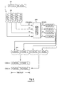
- Fig. 2 illustrates the operation of the second interleaving stage.
- the bits that come as an input stream 201 to the interleaver are written into a bit array 202 which has a certain number of rows and a certain number of columns.
- the numbers shown in the input stream and the bit array are simply the serial numbers of the bits in the radio frame.
- the number of columns is shown to be 32, with column numbers ranging from 0 to 31.
- the columns are fed into an intercolumn permutator 203 which rearranges them into a different order.
- the 0th column remains 0th
- the 17th column comes 1st
- the 14th column comes 30th
- the 31th column remains 31th after the intercolumn permutator 203.
- the bits are read from the permutated columns to the output of the second interleaving stage column by column.
- the bit stream 204 with the serial number of certain bits is shown as the output of the second interleaving stage.
- the TDD or Time Division Duplex mode with its possibility of simultaneously using several spreading codes brings about some complications to the presented arrangement.
- the bit stream 204 is transmitted by using that spreading code.
- the transmitting device has at least two spreading codes at its disposal, and it transmits by using these parallel spreading codes simultaneously during a single time slot.
- the presently defined physical channel mapping arrangement is such that the parallel spreading codes are filled one at a time with bits taken from the bit stream 204. This may lead to the situation shown at the bottom of Fig. 2 where, during a certain time slot, e.g. bits 0 and 14, bits 32 and 46 and so on of a certain frame are transmitted simultaneously.
- the number of parallel spreading codes may vary between 2 and 9.
- the arrangement according to Fig. 2 has the drawback of in the multicode situation canceling much of the advantages usually obtained through the second interleaving, because certain bits that are near to each other in the frame are practically not separated at all in the time domain at the radio interface.
- the nature of the interference occurring in UTRA systems is such that it may occur e.g. that a part of a time slot either from the very beginning or from the very end of the time slot gets erased due to interference, especially inter-operator interference.
- the result of such an erasure, taken the arrangement of Fig. 2 is a burst of errors very close to each other in a received frame.
- the objects of the invention are achived by modifying the order in which the bits are mapped into the spreading codes after the second interleaving stage.
- the method according to the invention is meant for interleaving a stream of data consisting of digital information symbols prior to transmission over a radio interface. It comprises the steps of
- the invention also applies to a transmitter arrangement which comprises
- the present invention is based on a finding that the mapping of bits into the parallel spreading codes has a key role in maintaining the separation of bits in the time domain.
- An advantageous way to eliminate the drawbacks of the existing arrangements is to modify the order in which the bits are mapped at least to a part of the spreading codes.
- the invention requires only a minor change in the existing proposed arrangements, and yet it provides a significant relief to the problem of maintaining sufficient separation in time domain between bits that are close to each other in the frame.
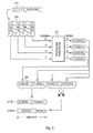
- Fig. 3 The upper part of Fig. 3 is similar to that of Fig. 2 :
- the bits that come as an input stream 201 to a second interleaver are written into a bit array 202 which has a certain number of rows and a certain number of columns.
- the number of columns is again 32, with column numbers ranging from 0 to 31.
- the columns are fed into an intercolumn permutator 203 which rearranges them into a different order.
- the present invention does not change the operation of the intercolumn permutator, so the 0th column remains 0th, the 17th column comes 1st, the 14th column comes 30th and the 31th column remains 31th after the intercolumn permutator 203 just as in the prior art arrangement of Fig. 2 .
- the invention pertains to the order in which the bits are read from the permutated columns to the output of the second interleaving stage, which is also the input of the physical channel mapping stage.
- the bit stream 204 with the serial number of certain bits is shown as the known output form of the second interleaving stage.
- the bits are mapped therefrom to the parallel spreading codes of which there are two in Fig. 3 , the order of bits in the component bit stream that goes into the second spreading code is reversed.
- Fig. 3 The principle shown in Fig. 3 is easily generalized to the case of N parallel spreading codes, where N is a positive integer greater than 2, by stating that the bit order in every second component bit stream is reversed before mapping that component bit stream into the corresponding spreading code.
- the invention does not limit the choice of the actual physical step in which the inverting of bit order is made for every second component bit stream.
- the system specifications of communications systems like the UTRA do not usually specify any particular hardware implementation for performing the standardized operations, but these are left into the discretion of transceiver designers.
- One advantageous way to perform the reversing is to integrate it into the step in which the bits are read from the bit array 202 after column permutation: the step of permutating columns does not mean anything else than correctly selecting the order in which bits are read from the memory locations where they are stored when they are said to be in the bit array.
- the transceiver may reorganize this reading order that in addition to the permutated order of columns, it takes into account the fact that those columns that go to the bit streams destined to be reversed are read in an inverted order and from bottom to top in the array representation.
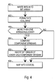
- Fig. 4 illustrates a method according to an advantageous embodiment of the invention in the form of a flow diagram.
- the steps shown in Fig. 4 belong functionally to the second interleaving stage 110 shown in Fig. 1 .
- Step 401 corresponds to writing the input bits into a bit array
- step 402 corresponds to permutating the columns.
- the transceiver checks the number of spreading codes it has at its disposal for transmitting this particular frame. If the number of codes is only one, the permutated columns are output in the known order so that they can be correctly mapped into the spreading code at step 406. If, however, there is a positive finding at step 403, component streams are (at least conceptually) composed at step 404 and in every second one of these the bit order is reversed at step 405.
- Fig. 5 illustrates the structure of a mobile terminal or base station where the parts from the CRC attacher 101 to the physical channel segmentator 109 may be similar as in known devices that conform to the TS 25.212 document mentioned in the description of prior art.
- the second interleaver 510 and the physical channel mapper 511 together are arranged to implement the method illustrated in Fig. 4 ; the physical implementation of the method is straightforward and within the capabilities of a person skilled in the art on the basis of the above-given instructions.
Landscapes
- Engineering & Computer Science (AREA)
- Physics & Mathematics (AREA)
- Probability & Statistics with Applications (AREA)
- Theoretical Computer Science (AREA)
- Computer Networks & Wireless Communication (AREA)
- Signal Processing (AREA)
- Error Detection And Correction (AREA)
- Detection And Prevention Of Errors In Transmission (AREA)
- Transmission Systems Not Characterized By The Medium Used For Transmission (AREA)
- Holo Graphy (AREA)
- Reverberation, Karaoke And Other Acoustics (AREA)
- Television Signal Processing For Recording (AREA)
Abstract
Description
- The invention concerns generally the technology of interleaving transmission symbols in a radio transceiver in time domain. Especially the invention concerns the technology of implementing intra-frame interleaving in multicode transceivers of the proposed UTRA (Universal Terrestrial Radio Access) system.
- The
Layer 1 multiplexing and channel coding characteristics of the FDD (Frequency Division Duplex) mode of the UTRA are, at the priority date of this patent application, defined in the document "TS 25.212 V3.0.0 (1999-10), 3rd Generation Partnership Project (3GPP); Technical Specification Group (TSG) Radio Access Network (RAN); Working Group 1 (WG1); Multiplexing and channel coding (FDD)" available through the 3GPP.Fig. 1 illustrates the transport channel multiplexing structure for uplink as defined in said document. The functional blocks the serial connection of which is shown in the upper part ofFig. 1 areCRC attachment 101, transport block concatenation andcode block segmentation 102,channel coding 103,radio frame equalisation 104,first interleaving 105,radio frame segmentation 106 and rate matching 107. Several entities of the above-described kind may be coupled to the inputs of a transportchannel multiplexing stage 108, the output of which is further coupled to the serial connection ofphysical channel segmentation 109, second interleaving 110 andphysical channel mapping 111. - In the downlink direction there may be certain modifications to the arrangement of functional blocks shown in
Fig. 1 , but at least the lower end of the arrangement which consists of the physical channel segmentation, second interleaving and physical channel mapping entities remains the same. For the purposes of the present invention it suffices to analyze the operation of the second interleaving and physical channel mapping blocks. - The aim of the
second interleaving 110 is to permutate the bits in time domain so that bits that originally were close to each other in the bit stream to be transmitted are separated from each other in the time domain for the duration of their travel over the radio interface. This way a short interval of extremely bad interference conditions at the radio interface should not cause any bursts of several consecutive erroneous bits in the received and decoded bit stream. Thesecond interleaving 110 takes place in intra-frame manner meaning that the data entity subjected to interleaving is one radio frame. -
Fig. 2 illustrates the operation of the second interleaving stage. The bits that come as aninput stream 201 to the interleaver are written into abit array 202 which has a certain number of rows and a certain number of columns. The numbers shown in the input stream and the bit array are simply the serial numbers of the bits in the radio frame. Here the number of columns is shown to be 32, with column numbers ranging from 0 to 31. The columns are fed into anintercolumn permutator 203 which rearranges them into a different order. As examples, the 0th column remains 0th, the 17th column comes 1st, the 14th column comes 30th and the 31th column remains 31th after theintercolumn permutator 203. The bits are read from the permutated columns to the output of the second interleaving stage column by column. Thebit stream 204 with the serial number of certain bits is shown as the output of the second interleaving stage. - The TDD or Time Division Duplex mode with its possibility of simultaneously using several spreading codes brings about some complications to the presented arrangement. If a single spreading code is used to transmit the bit stream, the
bit stream 204 is transmitted by using that spreading code. However, in a multicode situation the transmitting device has at least two spreading codes at its disposal, and it transmits by using these parallel spreading codes simultaneously during a single time slot. The presently defined physical channel mapping arrangement is such that the parallel spreading codes are filled one at a time with bits taken from thebit stream 204. This may lead to the situation shown at the bottom ofFig. 2 where, during a certain time slot,e.g. bits bits - The arrangement according to
Fig. 2 has the drawback of in the multicode situation canceling much of the advantages usually obtained through the second interleaving, because certain bits that are near to each other in the frame are practically not separated at all in the time domain at the radio interface. The nature of the interference occurring in UTRA systems is such that it may occur e.g. that a part of a time slot either from the very beginning or from the very end of the time slot gets erased due to interference, especially inter-operator interference. The result of such an erasure, taken the arrangement ofFig. 2 , is a burst of errors very close to each other in a received frame. - It is an object of the present invention to provide a method and an arrangement for ensuring that the separation in time between adjacent bits in a frame does not suffer in a multicode transmission arrangement. It is a further object of the invention that major changes in the existing proposed arrangements could be avoided.
- The objects of the invention are achived by modifying the order in which the bits are mapped into the spreading codes after the second interleaving stage.
- The method according to the invention is meant for interleaving a stream of data consisting of digital information symbols prior to transmission over a radio interface. It comprises the steps of
- performing a permutation to the stream of digital data, thus producing a permutated stream of digital data,
- producing, from the permutated stream of digital data, at least two component streams
- mapping each component stream into a spreading code.
- The invention also applies to a transmitter arrangement which comprises
- means for performing a permutation to the stream of digital data, thus producing a permutated stream of digital data,
- means for producing, from the permutated stream of digital data, at least two component streams
- means for mapping each component stream into a spreading code.
- The present invention is based on a finding that the mapping of bits into the parallel spreading codes has a key role in maintaining the separation of bits in the time domain. An advantageous way to eliminate the drawbacks of the existing arrangements is to modify the order in which the bits are mapped at least to a part of the spreading codes.
- In order not to cause major changes into the existing proposed arrangement it was found that if in every second one of the component bit streams that are parts of the output of the second interleaver the order of bits is inverted, sufficient separation in time domain between bits is maintained. Such a modification contains essentially no added complexity, because the order in which a certain finite bit stream is read (from first bit to last bit or from last bit to first bit) is merely a question of choosing a certain memory access command properly.
- The invention requires only a minor change in the existing proposed arrangements, and yet it provides a significant relief to the problem of maintaining sufficient separation in time domain between bits that are close to each other in the frame.
- The novel features which are considered as characteristic of the invention are set forth in particular in the appended claims. The invention itself, however, both as to its construction and its method of operation, together with additional objects and advantages thereof, will be best understood from the following description of specific embodiments when read in connection with the accompanying drawings.
- Fig. 1
- illustrates a known transport channel multiplexing structure for uplink,
- Fig. 2
- illustrates the results of second interleaving and code mapping in the arrangement of
Fig. 1 , - Fig. 3
- illustrates the results of second interleaving and code mapping according to an advantageous embodiment of the invention,
- Fig. 4
- is a flow diagram of the method according to the invention and
- Fig. 5
- illustrates a radio device according to an embodiment of the invention.
-
Figs. 1 and2 were already accounted for in the description of prior art. Like parts in the drawings are shown with the same reference designators. - The upper part of
Fig. 3 is similar to that ofFig. 2 : The bits that come as aninput stream 201 to a second interleaver are written into abit array 202 which has a certain number of rows and a certain number of columns. Here the number of columns is again 32, with column numbers ranging from 0 to 31. The columns are fed into anintercolumn permutator 203 which rearranges them into a different order. The present invention does not change the operation of the intercolumn permutator, so the 0th column remains 0th, the 17th column comes 1st, the 14th column comes 30th and the 31th column remains 31th after theintercolumn permutator 203 just as in the prior art arrangement ofFig. 2 . - The invention pertains to the order in which the bits are read from the permutated columns to the output of the second interleaving stage, which is also the input of the physical channel mapping stage. The
bit stream 204 with the serial number of certain bits is shown as the known output form of the second interleaving stage. However, when the bits are mapped therefrom to the parallel spreading codes of which there are two inFig. 3 , the order of bits in the component bit stream that goes into the second spreading code is reversed. - The principle shown in
Fig. 3 is easily generalized to the case of N parallel spreading codes, where N is a positive integer greater than 2, by stating that the bit order in every second component bit stream is reversed before mapping that component bit stream into the corresponding spreading code. - The invention does not limit the choice of the actual physical step in which the inverting of bit order is made for every second component bit stream. The system specifications of communications systems like the UTRA do not usually specify any particular hardware implementation for performing the standardized operations, but these are left into the discretion of transceiver designers. One advantageous way to perform the reversing is to integrate it into the step in which the bits are read from the
bit array 202 after column permutation: the step of permutating columns does not mean anything else than correctly selecting the order in which bits are read from the memory locations where they are stored when they are said to be in the bit array. The transceiver may reorganize this reading order that in addition to the permutated order of columns, it takes into account the fact that those columns that go to the bit streams destined to be reversed are read in an inverted order and from bottom to top in the array representation. -
Fig. 4 illustrates a method according to an advantageous embodiment of the invention in the form of a flow diagram. The steps shown inFig. 4 belong functionally to thesecond interleaving stage 110 shown inFig. 1 . Step 401 corresponds to writing the input bits into a bit array, and step 402 corresponds to permutating the columns. Atstep 403 the transceiver checks the number of spreading codes it has at its disposal for transmitting this particular frame. If the number of codes is only one, the permutated columns are output in the known order so that they can be correctly mapped into the spreading code atstep 406. If, however, there is a positive finding atstep 403, component streams are (at least conceptually) composed atstep 404 and in every second one of these the bit order is reversed atstep 405. -
Fig. 5 illustrates the structure of a mobile terminal or base station where the parts from the CRC attacher 101 to thephysical channel segmentator 109 may be similar as in known devices that conform to the TS 25.212 document mentioned in the description of prior art. Thesecond interleaver 510 and thephysical channel mapper 511 together are arranged to implement the method illustrated inFig. 4 ; the physical implementation of the method is straightforward and within the capabilities of a person skilled in the art on the basis of the above-given instructions. - The above-given exemplary embodiments should not be construed as limiting the applicability of the invention; the latter is merely reflected in the scope of the appended claims. For example the invention does not require that an interleaving operation where every second component stream to be mapped into a spreading code should be limited to interleaving within a single time slot. Similarly the permutation and order inverting operations may be performed on groups of bits (e.g. so that three consecutive bits constitute a group) instead of just bits.
Claims (6)
- A method, comprising:- performing a permutation for a stream of digital data, thus producing a permuted stream of digital data,- producing at least two component streams from the permuted stream of digital data,- reversing the order of bits in at least one component stream, and- mapping both such component streams, the order of bits of which has not been reversed, and such component streams, the order of bits of which has been reversed, to physical channels.
- A method according to claim 1, wherein for performing second interleaving and physical channel mapping to a stream of data (201) consisting of bits prior to transmission over a radio interface, the method comprises:- performing an intercolumn permutation (202, 203, 401, 402) for a permutation matrix the columns of which contain bits of the stream of digital data, thus producing an inter-column permuted matrix,- reading bits from the columns of the inter-column permuted matrix to the output of the second interleaving, thus producingat least two component streams (404), and- mapping each component stream to a physical channel (511) so that when the bits of the component streams are mapped to the physical channels, the order of bits in every second component bit stream is reversed.
- A radio device, comprising:- means for performing a permutation for a stream of digital data and for thus producing a permuted stream of digital data,- means for producing at least two component streams from the permuted stream of digital data,- means for reversing the order of bits in at least one component stream, and- means for mapping both such component streams, the order of bits of which has not been reversed, and such component streams, the order of bits of which has been reversed, to physical channels.
- A radio device according to claim 3, comprising means for performing second interleaving (510) and physical channel mapping to a stream of data (201) consisting of bits prior to transmission over a radio interface, comprising:- means for performing an intercolumn permutation (202, 203, 401, 402) for a permutation matrix the columns of which contain bits of the stream of digital data, thus producing an inter-column permuted matrix,- means for reading bits from the columns of the inter-column permuted matrix to the output of the second interleaving, thus producing at least two component streams, and- means for mapping each component stream to a physical channel so that when the bits of the component streams are mapped to the physical channels, the order of bits in every second component bit stream is reversed.
- A radio device according to claim 3 or 4, characterized in that it is a mobile terminal of a 3GPP radio communication system.
- A radio device according to claim 3 or 4, characterized in that it is a base station of a 3GPP radio communication system.
Priority Applications (1)
| Application Number | Priority Date | Filing Date | Title |
|---|---|---|---|
| EP20140172435 EP2824842A3 (en) | 1999-11-30 | 2000-11-29 | Method and arrangement for implementing intra-frame interleaving |
Applications Claiming Priority (2)
| Application Number | Priority Date | Filing Date | Title |
|---|---|---|---|
| FI992561A FI114766B (en) | 1999-11-30 | 1999-11-30 | Method and arrangement for realizing co-sorting internally in frames |
| EP00983366A EP1247344B1 (en) | 1999-11-30 | 2000-11-29 | Method and arrangement for implementing intra-frame interleaving |
Related Parent Applications (1)
| Application Number | Title | Priority Date | Filing Date |
|---|---|---|---|
| EP00983366A Division EP1247344B1 (en) | 1999-11-30 | 2000-11-29 | Method and arrangement for implementing intra-frame interleaving |
Related Child Applications (2)
| Application Number | Title | Priority Date | Filing Date |
|---|---|---|---|
| EP20140172435 Division EP2824842A3 (en) | 1999-11-30 | 2000-11-29 | Method and arrangement for implementing intra-frame interleaving |
| EP20140172435 Division-Into EP2824842A3 (en) | 1999-11-30 | 2000-11-29 | Method and arrangement for implementing intra-frame interleaving |
Publications (3)
| Publication Number | Publication Date |
|---|---|
| EP1968199A2 true EP1968199A2 (en) | 2008-09-10 |
| EP1968199A3 EP1968199A3 (en) | 2009-06-10 |
| EP1968199B1 EP1968199B1 (en) | 2014-07-30 |
Family
ID=8555666
Family Applications (3)
| Application Number | Title | Priority Date | Filing Date |
|---|---|---|---|
| EP20140172435 Withdrawn EP2824842A3 (en) | 1999-11-30 | 2000-11-29 | Method and arrangement for implementing intra-frame interleaving |
| EP00983366A Expired - Lifetime EP1247344B1 (en) | 1999-11-30 | 2000-11-29 | Method and arrangement for implementing intra-frame interleaving |
| EP08159169.5A Expired - Lifetime EP1968199B1 (en) | 1999-11-30 | 2000-11-29 | Method and device for implementing intra-frame interleaving |
Family Applications Before (2)
| Application Number | Title | Priority Date | Filing Date |
|---|---|---|---|
| EP20140172435 Withdrawn EP2824842A3 (en) | 1999-11-30 | 2000-11-29 | Method and arrangement for implementing intra-frame interleaving |
| EP00983366A Expired - Lifetime EP1247344B1 (en) | 1999-11-30 | 2000-11-29 | Method and arrangement for implementing intra-frame interleaving |
Country Status (15)
| Country | Link |
|---|---|
| US (1) | US6904077B2 (en) |
| EP (3) | EP2824842A3 (en) |
| JP (1) | JP3331209B2 (en) |
| KR (1) | KR100680120B1 (en) |
| CN (1) | CN1402910B (en) |
| AT (1) | ATE435528T1 (en) |
| AU (1) | AU773939B2 (en) |
| BR (1) | BR0014627A (en) |
| CA (1) | CA2392707C (en) |
| DE (1) | DE60042495D1 (en) |
| ES (2) | ES2325876T3 (en) |
| FI (1) | FI114766B (en) |
| MX (1) | MXPA02005332A (en) |
| PT (1) | PT1247344E (en) |
| WO (1) | WO2001041314A1 (en) |
Families Citing this family (18)
| Publication number | Priority date | Publication date | Assignee | Title |
|---|---|---|---|---|
| JP2001285077A (en) * | 2000-03-31 | 2001-10-12 | Mitsubishi Electric Corp | Communication device and communication method |
| WO2002017549A2 (en) * | 2000-08-25 | 2002-02-28 | Sasken Communication Technologies Limited | A technique for reducing processing power in 3g systems |
| GB0120535D0 (en) * | 2001-08-23 | 2001-10-17 | Roke Manor Research | Space-time interleaving transmit diversity |
| US7292552B2 (en) | 2002-03-14 | 2007-11-06 | Qualcomm Incorporated | Method and apparatus for reducing interference in a wireless communication system |
| US7035284B2 (en) | 2002-03-14 | 2006-04-25 | Qualcomm Incorporated | Method and apparatus for reducing inter-channel interference in a wireless communication system employing a non-periodic interleaver |
| GB2387515A (en) | 2002-04-08 | 2003-10-15 | Ipwireless Inc | Mapping bits to at least two channels using two interleavers, one for systematic bits, and the other for parity bits |
| US6919829B2 (en) † | 2003-06-20 | 2005-07-19 | Nokia Corporation | Bit swapping for different interleaving depths |
| CN1655488B (en) * | 2004-02-11 | 2010-12-15 | 诺基亚西门子通信系统技术(北京)有限公司 | Method for increasing interleaving time in radio communication systems |
| JP2005318291A (en) * | 2004-04-28 | 2005-11-10 | Yamaha Corp | Data transmission method, server device, data receiving device, and data transmission system. |
| US7570698B2 (en) * | 2004-11-16 | 2009-08-04 | Intel Corporation | Multiple output multicarrier transmitter and methods for spatial interleaving a plurality of spatial streams |
| US7542410B2 (en) * | 2004-12-06 | 2009-06-02 | Intel Corporation | Interleaver and associated methods |
| US20070044126A1 (en) * | 2005-08-18 | 2007-02-22 | Rockwell Collins, Inc. | Wireless video entertainment system |
| US8769365B2 (en) | 2010-10-08 | 2014-07-01 | Blackberry Limited | Message rearrangement for improved wireless code performance |
| CN103430472B (en) * | 2010-10-08 | 2017-05-24 | 黑莓有限公司 | Message rearrangement for improved code performance |
| US8850276B2 (en) * | 2011-09-22 | 2014-09-30 | Lsi Corporation | Systems and methods for efficient data shuffling in a data processing system |
| US9043667B2 (en) | 2011-11-04 | 2015-05-26 | Blackberry Limited | Method and system for up-link HARQ-ACK and CSI transmission |
| KR102127021B1 (en) | 2012-05-11 | 2020-06-26 | 블랙베리 리미티드 | Method and system for uplink harq and csi multiplexing for carrier aggregation |
| KR102383060B1 (en) * | 2021-02-09 | 2022-04-08 | 어메이징썬 주식회사 | Electric kickboard |
Family Cites Families (14)
| Publication number | Priority date | Publication date | Assignee | Title |
|---|---|---|---|---|
| US4547887A (en) * | 1983-11-30 | 1985-10-15 | The United States Of America As Represented By The Secretary Of The Army | Pseudo-random convolutional interleaving |
| US5056112A (en) * | 1989-07-28 | 1991-10-08 | At&T Bell Laboratories | Interleaving in coded modulation for mobile radio |
| WO1995018494A1 (en) * | 1993-12-29 | 1995-07-06 | Zenith Electronics Corporation | Data frame format for variable size data constellations |
| US5602875A (en) * | 1995-01-13 | 1997-02-11 | Motorola, Inc. | Method and apparatus for encoding and decoding information in a digtial communication system |
| US5796755A (en) | 1995-10-10 | 1998-08-18 | Eastman Kodak Company | Error minimization in interleaved error correcting codes |
| US5996104A (en) | 1996-09-13 | 1999-11-30 | Herzberg; Hanan | System for coding system |
| US6373831B1 (en) | 1997-03-26 | 2002-04-16 | Nortel Networks Ltd. | Systems and methods of channel coding and inverse-multiplexing for multi-carrier CDMA systems |
| US6421333B1 (en) | 1997-06-21 | 2002-07-16 | Nortel Networks Limited | Channel coding and interleaving for transmission on a multicarrier system |
| KR100330980B1 (en) | 1997-11-10 | 2002-04-01 | 다치카와 게이지 | Interleaving method, interleaving apparatus, and recording medium in which interleave pattern generating program is recorded |
| US6304581B1 (en) | 1999-02-16 | 2001-10-16 | Motorola, Inc. | Interleaving method and apparatus for orthogonal transmit diversity and multi-carriers CDMA communication systems |
| FR2792128B1 (en) | 1999-04-07 | 2001-09-07 | Mitsubishi Electric France | METHOD AND DEVICE FOR CHANNEL INTERLACING AND MULTIPLEXING |
| CA2742096C (en) | 1999-04-13 | 2015-01-06 | Ericsson Ab | Rate matching and channel interleaving for a communications system |
| US6311306B1 (en) * | 1999-04-26 | 2001-10-30 | Motorola, Inc. | System for error control by subdividing coded information units into subsets reordering and interlacing the subsets, to produce a set of interleaved coded information units |
| US6259744B1 (en) * | 1999-06-01 | 2001-07-10 | Motorola, Inc. | Method and apparatus for mapping bits to an information burst |
-
1999
- 1999-11-30 FI FI992561A patent/FI114766B/en not_active IP Right Cessation
-
2000
- 2000-11-28 JP JP2000361468A patent/JP3331209B2/en not_active Expired - Fee Related
- 2000-11-29 US US09/726,079 patent/US6904077B2/en not_active Expired - Lifetime
- 2000-11-29 CA CA002392707A patent/CA2392707C/en not_active Expired - Fee Related
- 2000-11-29 KR KR1020027005554A patent/KR100680120B1/en not_active Expired - Fee Related
- 2000-11-29 DE DE60042495T patent/DE60042495D1/en not_active Expired - Lifetime
- 2000-11-29 EP EP20140172435 patent/EP2824842A3/en not_active Withdrawn
- 2000-11-29 BR BR0014627-7A patent/BR0014627A/en active Search and Examination
- 2000-11-29 WO PCT/FI2000/001037 patent/WO2001041314A1/en not_active Ceased
- 2000-11-29 PT PT00983366T patent/PT1247344E/en unknown
- 2000-11-29 EP EP00983366A patent/EP1247344B1/en not_active Expired - Lifetime
- 2000-11-29 AT AT00983366T patent/ATE435528T1/en not_active IP Right Cessation
- 2000-11-29 AU AU20132/01A patent/AU773939B2/en not_active Ceased
- 2000-11-29 CN CN008165033A patent/CN1402910B/en not_active Expired - Lifetime
- 2000-11-29 EP EP08159169.5A patent/EP1968199B1/en not_active Expired - Lifetime
- 2000-11-29 ES ES00983366T patent/ES2325876T3/en not_active Expired - Lifetime
- 2000-11-29 MX MXPA02005332A patent/MXPA02005332A/en active IP Right Grant
- 2000-11-29 ES ES08159169.5T patent/ES2500492T3/en not_active Expired - Lifetime
Non-Patent Citations (1)
| Title |
|---|
| ANONYMOUS: "3G TS 25 212 V3.0.0" INTERNET ARTICLE, [Online] October 1999 (1999-10), XP002525383 Retrieved from the Internet: URL:http://www.3gpp.org/ftp/Specs/html-info/25212.htm> [retrieved on 2009-04-24] * |
Also Published As
| Publication number | Publication date |
|---|---|
| US6904077B2 (en) | 2005-06-07 |
| CA2392707C (en) | 2008-09-09 |
| WO2001041314A1 (en) | 2001-06-07 |
| EP2824842A2 (en) | 2015-01-14 |
| ATE435528T1 (en) | 2009-07-15 |
| ES2325876T3 (en) | 2009-09-23 |
| CN1402910A (en) | 2003-03-12 |
| WO2001041314A8 (en) | 2001-09-07 |
| EP1968199B1 (en) | 2014-07-30 |
| KR20020048998A (en) | 2002-06-24 |
| MXPA02005332A (en) | 2002-12-06 |
| DE60042495D1 (en) | 2009-08-13 |
| ES2500492T3 (en) | 2014-09-30 |
| PT1247344E (en) | 2009-07-20 |
| US20010053173A1 (en) | 2001-12-20 |
| CN1402910B (en) | 2010-05-05 |
| HK1118646A1 (en) | 2009-02-13 |
| EP2824842A3 (en) | 2015-04-08 |
| EP1247344B1 (en) | 2009-07-01 |
| EP1968199A3 (en) | 2009-06-10 |
| JP2001197035A (en) | 2001-07-19 |
| JP3331209B2 (en) | 2002-10-07 |
| FI114766B (en) | 2004-12-15 |
| BR0014627A (en) | 2002-06-11 |
| EP1247344A2 (en) | 2002-10-09 |
| AU773939B2 (en) | 2004-06-10 |
| FI19992561L (en) | 2001-05-31 |
| CA2392707A1 (en) | 2001-06-07 |
| AU2013201A (en) | 2001-06-12 |
| KR100680120B1 (en) | 2007-02-07 |
Similar Documents
| Publication | Publication Date | Title |
|---|---|---|
| EP1968199B1 (en) | Method and device for implementing intra-frame interleaving | |
| CN100499442C (en) | Device and method for transmitting or receiving data in communication system | |
| KR100446537B1 (en) | Method and device for transmitting packet data in mobile communication system | |
| KR100605811B1 (en) | Derate matching method and apparatus thereof in high speed packet transmission system | |
| KR101498052B1 (en) | Method for multiplexing data information and control information in a wireless mobile communication system | |
| CN1086522C (en) | Receiver-transmitter unit in mobile communication system | |
| KR20010107737A (en) | Data transmission apparatus and method for an harq data communication system | |
| KR100593496B1 (en) | Method and system for assigning convolutional coded bits to symbols before modulation | |
| CN101325739A (en) | Method for transmitting uplink data and uplink control signaling | |
| KR20020079856A (en) | Method for adapting the data blocks to be supplied to a turbo coder and a corresponding communications device | |
| CN1108016C (en) | Coding device and method | |
| US6901113B2 (en) | Processing methods and devices for sending information symbols over multiplexed channels, and corresponding processing methods and devices for reception | |
| KR20020068352A (en) | Wireless transmission device and transmission signal mapping method | |
| KR100720772B1 (en) | Method and apparatus for matching transmission rates | |
| EP1396096B1 (en) | System and method for interleaving data in a wireless transmitter | |
| KR101308927B1 (en) | Apparatus and methods using a linear memory model for encoder output buffers | |
| HK1118646B (en) | Method and device for implementing intra-frame interleaving | |
| FI109569B (en) | Method and arrangement for allocating time intervals for a connected control channel | |
| EP0465144A2 (en) | Method and apparatus for interleaving symbols in a cellular transmission channel | |
| CN101060382B (en) | A multiple time slot joint coding method | |
| KR100519334B1 (en) | Block Interleaver and method thereof | |
| Li et al. | Hybrid Type-II ARQ Schemes with Scheduling for Packet Data Transmission over Rayleigh Fading Channels |
Legal Events
| Date | Code | Title | Description |
|---|---|---|---|
| PUAI | Public reference made under article 153(3) epc to a published international application that has entered the european phase |
Free format text: ORIGINAL CODE: 0009012 |
|
| AC | Divisional application: reference to earlier application |
Ref document number: 1247344 Country of ref document: EP Kind code of ref document: P |
|
| AK | Designated contracting states |
Kind code of ref document: A2 Designated state(s): AT BE CH CY DE DK ES FI FR GB GR IE IT LI LU MC NL PT SE TR |
|
| REG | Reference to a national code |
Ref country code: HK Ref legal event code: DE Ref document number: 1118646 Country of ref document: HK |
|
| PUAL | Search report despatched |
Free format text: ORIGINAL CODE: 0009013 |
|
| AK | Designated contracting states |
Kind code of ref document: A3 Designated state(s): AT BE CH CY DE DK ES FI FR GB GR IE IT LI LU MC NL PT SE TR |
|
| 17P | Request for examination filed |
Effective date: 20090624 |
|
| 17Q | First examination report despatched |
Effective date: 20090806 |
|
| AKX | Designation fees paid |
Designated state(s): AT BE CH CY DE DK ES FI FR GB GR IE IT LI LU MC NL PT SE TR |
|
| RAP1 | Party data changed (applicant data changed or rights of an application transferred) |
Owner name: 2011 INTELLECTUAL PROPERTY ASSET TRUST |
|
| RAP1 | Party data changed (applicant data changed or rights of an application transferred) |
Owner name: CORE WIRELESS LICENSING S.A.R.L. |
|
| GRAP | Despatch of communication of intention to grant a patent |
Free format text: ORIGINAL CODE: EPIDOSNIGR1 |
|
| INTG | Intention to grant announced |
Effective date: 20140204 |
|
| GRAS | Grant fee paid |
Free format text: ORIGINAL CODE: EPIDOSNIGR3 |
|
| RIN1 | Information on inventor provided before grant (corrected) |
Inventor name: AKSENTIJEVIC, MIRKO Inventor name: TOSKALA, ANTTI |
|
| GRAA | (expected) grant |
Free format text: ORIGINAL CODE: 0009210 |
|
| AC | Divisional application: reference to earlier application |
Ref document number: 1247344 Country of ref document: EP Kind code of ref document: P |
|
| AK | Designated contracting states |
Kind code of ref document: B1 Designated state(s): AT BE CH CY DE DK ES FI FR GB GR IE IT LI LU MC NL PT SE TR |
|
| REG | Reference to a national code |
Ref country code: GB Ref legal event code: FG4D |
|
| REG | Reference to a national code |
Ref country code: CH Ref legal event code: EP |
|
| REG | Reference to a national code |
Ref country code: AT Ref legal event code: REF Ref document number: 680376 Country of ref document: AT Kind code of ref document: T Effective date: 20140815 |
|
| REG | Reference to a national code |
Ref country code: IE Ref legal event code: FG4D |
|
| REG | Reference to a national code |
Ref country code: DE Ref legal event code: R096 Ref document number: 60048678 Country of ref document: DE Effective date: 20140911 |
|
| REG | Reference to a national code |
Ref country code: ES Ref legal event code: FG2A Ref document number: 2500492 Country of ref document: ES Kind code of ref document: T3 Effective date: 20140930 |
|
| REG | Reference to a national code |
Ref country code: SE Ref legal event code: TRGR |
|
| REG | Reference to a national code |
Ref country code: HK Ref legal event code: GR Ref document number: 1118646 Country of ref document: HK |
|
| REG | Reference to a national code |
Ref country code: NL Ref legal event code: T3 |
|
| REG | Reference to a national code |
Ref country code: AT Ref legal event code: MK05 Ref document number: 680376 Country of ref document: AT Kind code of ref document: T Effective date: 20140730 |
|
| PG25 | Lapsed in a contracting state [announced via postgrant information from national office to epo] |
Ref country code: PT Free format text: LAPSE BECAUSE OF FAILURE TO SUBMIT A TRANSLATION OF THE DESCRIPTION OR TO PAY THE FEE WITHIN THE PRESCRIBED TIME-LIMIT Effective date: 20141202 Ref country code: GR Free format text: LAPSE BECAUSE OF FAILURE TO SUBMIT A TRANSLATION OF THE DESCRIPTION OR TO PAY THE FEE WITHIN THE PRESCRIBED TIME-LIMIT Effective date: 20141031 |
|
| PGFP | Annual fee paid to national office [announced via postgrant information from national office to epo] |
Ref country code: SE Payment date: 20141111 Year of fee payment: 15 Ref country code: IE Payment date: 20141110 Year of fee payment: 15 Ref country code: ES Payment date: 20141013 Year of fee payment: 15 Ref country code: FI Payment date: 20141110 Year of fee payment: 15 Ref country code: GB Payment date: 20141126 Year of fee payment: 15 Ref country code: DE Payment date: 20141125 Year of fee payment: 15 |
|
| PG25 | Lapsed in a contracting state [announced via postgrant information from national office to epo] |
Ref country code: CY Free format text: LAPSE BECAUSE OF FAILURE TO SUBMIT A TRANSLATION OF THE DESCRIPTION OR TO PAY THE FEE WITHIN THE PRESCRIBED TIME-LIMIT Effective date: 20140730 Ref country code: AT Free format text: LAPSE BECAUSE OF FAILURE TO SUBMIT A TRANSLATION OF THE DESCRIPTION OR TO PAY THE FEE WITHIN THE PRESCRIBED TIME-LIMIT Effective date: 20140730 |
|
| PGFP | Annual fee paid to national office [announced via postgrant information from national office to epo] |
Ref country code: NL Payment date: 20141108 Year of fee payment: 15 |
|
| PGFP | Annual fee paid to national office [announced via postgrant information from national office to epo] |
Ref country code: IT Payment date: 20141110 Year of fee payment: 15 |
|
| PG25 | Lapsed in a contracting state [announced via postgrant information from national office to epo] |
Ref country code: DK Free format text: LAPSE BECAUSE OF FAILURE TO SUBMIT A TRANSLATION OF THE DESCRIPTION OR TO PAY THE FEE WITHIN THE PRESCRIBED TIME-LIMIT Effective date: 20140730 |
|
| PGFP | Annual fee paid to national office [announced via postgrant information from national office to epo] |
Ref country code: BE Payment date: 20141111 Year of fee payment: 15 |
|
| REG | Reference to a national code |
Ref country code: DE Ref legal event code: R097 Ref document number: 60048678 Country of ref document: DE |
|
| PLBE | No opposition filed within time limit |
Free format text: ORIGINAL CODE: 0009261 |
|
| STAA | Information on the status of an ep patent application or granted ep patent |
Free format text: STATUS: NO OPPOSITION FILED WITHIN TIME LIMIT |
|
| PG25 | Lapsed in a contracting state [announced via postgrant information from national office to epo] |
Ref country code: MC Free format text: LAPSE BECAUSE OF FAILURE TO SUBMIT A TRANSLATION OF THE DESCRIPTION OR TO PAY THE FEE WITHIN THE PRESCRIBED TIME-LIMIT Effective date: 20140730 Ref country code: LU Free format text: LAPSE BECAUSE OF FAILURE TO SUBMIT A TRANSLATION OF THE DESCRIPTION OR TO PAY THE FEE WITHIN THE PRESCRIBED TIME-LIMIT Effective date: 20141129 |
|
| REG | Reference to a national code |
Ref country code: CH Ref legal event code: PL |
|
| 26N | No opposition filed |
Effective date: 20150504 |
|
| PG25 | Lapsed in a contracting state [announced via postgrant information from national office to epo] |
Ref country code: LI Free format text: LAPSE BECAUSE OF NON-PAYMENT OF DUE FEES Effective date: 20141130 Ref country code: CH Free format text: LAPSE BECAUSE OF NON-PAYMENT OF DUE FEES Effective date: 20141130 |
|
| REG | Reference to a national code |
Ref country code: FR Ref legal event code: PLFP Year of fee payment: 16 |
|
| REG | Reference to a national code |
Ref country code: DE Ref legal event code: R119 Ref document number: 60048678 Country of ref document: DE |
|
| GBPC | Gb: european patent ceased through non-payment of renewal fee |
Effective date: 20151129 |
|
| PG25 | Lapsed in a contracting state [announced via postgrant information from national office to epo] |
Ref country code: IT Free format text: LAPSE BECAUSE OF NON-PAYMENT OF DUE FEES Effective date: 20151129 Ref country code: TR Free format text: LAPSE BECAUSE OF FAILURE TO SUBMIT A TRANSLATION OF THE DESCRIPTION OR TO PAY THE FEE WITHIN THE PRESCRIBED TIME-LIMIT Effective date: 20140730 |
|
| REG | Reference to a national code |
Ref country code: NL Ref legal event code: MM Effective date: 20151201 |
|
| REG | Reference to a national code |
Ref country code: IE Ref legal event code: MM4A |
|
| PG25 | Lapsed in a contracting state [announced via postgrant information from national office to epo] |
Ref country code: SE Free format text: LAPSE BECAUSE OF NON-PAYMENT OF DUE FEES Effective date: 20151130 |
|
| PG25 | Lapsed in a contracting state [announced via postgrant information from national office to epo] |
Ref country code: NL Free format text: LAPSE BECAUSE OF NON-PAYMENT OF DUE FEES Effective date: 20151201 |
|
| PG25 | Lapsed in a contracting state [announced via postgrant information from national office to epo] |
Ref country code: GB Free format text: LAPSE BECAUSE OF NON-PAYMENT OF DUE FEES Effective date: 20151129 Ref country code: IE Free format text: LAPSE BECAUSE OF NON-PAYMENT OF DUE FEES Effective date: 20151129 Ref country code: DE Free format text: LAPSE BECAUSE OF NON-PAYMENT OF DUE FEES Effective date: 20160601 |
|
| REG | Reference to a national code |
Ref country code: ES Ref legal event code: FD2A Effective date: 20161228 |
|
| PG25 | Lapsed in a contracting state [announced via postgrant information from national office to epo] |
Ref country code: ES Free format text: LAPSE BECAUSE OF NON-PAYMENT OF DUE FEES Effective date: 20151130 |
|
| REG | Reference to a national code |
Ref country code: FR Ref legal event code: PLFP Year of fee payment: 17 |
|
| PG25 | Lapsed in a contracting state [announced via postgrant information from national office to epo] |
Ref country code: FI Free format text: LAPSE BECAUSE OF NON-PAYMENT OF DUE FEES Effective date: 20151129 |
|
| PG25 | Lapsed in a contracting state [announced via postgrant information from national office to epo] |
Ref country code: BE Free format text: LAPSE BECAUSE OF NON-PAYMENT OF DUE FEES Effective date: 20151130 |
|
| REG | Reference to a national code |
Ref country code: FR Ref legal event code: PLFP Year of fee payment: 18 |
|
| REG | Reference to a national code |
Ref country code: FR Ref legal event code: PLFP Year of fee payment: 19 |
|
| PGFP | Annual fee paid to national office [announced via postgrant information from national office to epo] |
Ref country code: FR Payment date: 20191014 Year of fee payment: 20 |