EP1968100B1 - Ion guide chamber - Google Patents
Ion guide chamber Download PDFInfo
- Publication number
- EP1968100B1 EP1968100B1 EP07405077.4A EP07405077A EP1968100B1 EP 1968100 B1 EP1968100 B1 EP 1968100B1 EP 07405077 A EP07405077 A EP 07405077A EP 1968100 B1 EP1968100 B1 EP 1968100B1
- Authority
- EP
- European Patent Office
- Prior art keywords
- chamber
- ion guide
- ions
- field
- recited
- Prior art date
- Legal status (The legal status is an assumption and is not a legal conclusion. Google has not performed a legal analysis and makes no representation as to the accuracy of the status listed.)
- Active
Links
Images
Classifications
-
- H—ELECTRICITY
- H01—ELECTRIC ELEMENTS
- H01J—ELECTRIC DISCHARGE TUBES OR DISCHARGE LAMPS
- H01J49/00—Particle spectrometers or separator tubes
- H01J49/02—Details
- H01J49/04—Arrangements for introducing or extracting samples to be analysed, e.g. vacuum locks; Arrangements for external adjustment of electron- or ion-optical components
Definitions
- the invention relates to an ion guide chamber, comprising a gas-tight elongate chamber, at least one first electrode for generating a field for transporting ions along said elongate chamber and at least one second electrode for generating a field for focusing the ions within the elongate chamber.
- the invention further relates to an apparatus for mass analysis comprising such an ion chamber.
- MS Mass spectrometry
- Mass spectrometry involves the measurement of the mass-to-charge ratio of ions. In many applications these ions are created in high pressure ion sources. Many mass analyzing devices however require that the ions are injected into a high vacuum chamber. Therefore, it has been proposed to transfer the ions from the high pressure ion source into the high vacuum through an intermediate pressure region. Often, the ions have to pass one or several differentially pumped stages for the transfer into the high vacuum of the MS.
- a first field is used for transport of ions through the residual gas from the entrance to the exit.
- the field direction is essentially parallel to the chamber main axis, and the field can be static.
- a second electric field is applied for confining the ions close to the axis.
- This is often done with an RF field with low amplitudes on the chamber axis and larger amplitudes away from the axis.
- Such an RF field creates an effective potential confining the ions to the axis. Examples of such fields are RF multipole fields.
- the transport field controls the axial ion movement and directs the ions towards the exit orifice into the (next) higher vacuum, whereas the RF field confines the ions to the center axis within the chamber.
- the superposition of a linear field and an RF field is achieved by tilting the quadrupole electrodes towards the central axis, or by using quadrupole electrodes of tempered shape instead of cylindrical shape.
- the elongate chamber comprises a resistive structure extending substantially along a main axis of the chamber, whereas the first electrode, i. e. the electrode for generating the field for transporting the ions along the elongate chamber, is constituted by the resistive structure.
- the second electrode for generating the field for focusing the ions within the elongate chamber is arranged outside the elongate chamber.
- the geometry of the invention having the RF electrodes arranged outside the vacuum chamber, provides a mechanically simple solution. Furthermore, having the electrodes outside the glass tube has the big advantage that contamination of the RF electrodes to the analyte gas cannot occur. This allows for a cost-saving design of the RF electrodes. Furthermore, having the RF electrodes with the corresponding voltages outside the chamber, preferably at atmospheric pressure or at high vacuum, minimizes the discharge problem mentioned above.
- the transporting field controls ion energies, which allows controlling fragmentation, and decreases residence times, which is often desired in hyphenated MS techniques.
- an apparatus for mass analysis according to the invention comprises:
- inventive ion guide chamber or each of the subsequently arranged inventive ion guide chambers, respectively allows for decreasing the pressure the inventive device is particularly suitable for guiding ions from high pressure ion sources arranged upstream of the at least one ion guide chamber to the mass spectrometer arranged downstream of the at least one ion guide chamber.
- the analyte ions are directly generated in a pulsed manner by the ion source. This saves the upstream ion gate.
- the ion guide chamber is operated as an ion source, i. e. the analyte ions are formed within the ion guide chamber by photo ionization or by any other ionization techniques that can take place under elevated pressure.
- the ion guide chamber is used as a reaction chamber.
- it preferably features a first inlet for analyte molecules and a second inlet for a primary particle beam. Because of the RF confinement of the primary ions, their ion density and thus numbers of reaction products are increased in the center axis of the tube. The analyte ions are mainly generated along the axis and their probability to be transferred through the exit orifice into the high vacuum is therefore high.
- the reaction chamber described above can serve different purposes. Often the sample is embedded in a much more abundant matrix that is of no interest in the analysis. For example, when analyzing air quality the major air components N 2 , O 2 and Ar are usually of no analytical interest. In such a case it is of advantage to use selective ionization that only ionizes the trace gases of interest but not the major components. Ionizing the major components would create a vast amount of ions that could saturate the MS system and hinder the detection of the trace ions. Several selective ion sources have been developed for this reason. Among them are single photon ionization (SPI), metastable atom beam ionization (MAB), and a large variety of ionization schemes by chemical reactions where selective reactions are used to ionize the trace samples but not the matrix.
- SPI single photon ionization
- MAB metastable atom beam ionization
- a large variety of ionization schemes by chemical reactions where selective reactions are used to ionize the trace
- the elongate chamber is constituted by a glass tube, in particular of circular cross-section.
- the tube can be bent, which is sometimes required in order to transport ions from non-coaxial orifices or in order to minimize the flux of photons through the orifices.
- the resistive structure may be constituted by a resistive coating on the inside and/or outside of the elongate chamber, in particular in cases where the elongate chamber is made from an isolating material such as e. g. isolating glass. It is preferred to apply the coating to the outside of the elongate chamber only as this allows for using paints that are not necessarily free of outgasing.
- the coating can be applied on the whole surface or in the form of structures as for example a spiral extending along the tube.
- the invention is realized with a chamber made from a resistive material such as resistive glass, resistive plastic or resistive ceramics. This makes an additional coating unnecessary.
- a resistance measured along the chamber main axis, between a first end of the resistive structure and a second end of the resistive structure opposite to the first end is at least 1 M ⁇ , preferably at least 5 M ⁇ . This ensures that the field for focusing the ions generated by the second electrode arranged outside the elongate chamber may penetrate into the chamber. At the same time, reliable transport of the ions along the chamber is provided for.
- the at least one second electrode comprises a set of elongated rods arranged substantially parallel to the elongated chamber.
- the rods may be conducting or semi conducting. Their cross-section may be e. g. circular or parabolic.
- the at least one second electrode is constituted by at least one electrically conductive or semi-conductive coated or painted surface region on an outside of the elongated chamber.
- the electrode is arranged outside the chamber problems due to outgasing electrode materials are avoided.
- using a painted electrode allows for a design of the ion guide chamber that is at the same time very compact and robust. Neither is there a need for rod fixtures, nor is it necessary to adjust and/or calibrate focusing electrodes with respect to the guide chamber.
- the field for transporting the ions runs parallel to the chamber main axis and the field for focussing the ions is an RF multipole field generating an effective potential confining the ions to a region neighboring the chamber main axis.
- the primary confining field may also consist of a superposition of multipole fields.
- Linear RF multipole fields that are particularly well adapted for the inventive ion guide are usually produced using co-axial rods of parabolic or circular shape. Other shapes may be used e. g. in order to approximate quadrupole fields.
- a primary RF-only field is applied between opposing set of rods.
- the second field generating device is capable of generating a rotating multipole field at the at least one second electrode, in particular a rotating quadrupole field.
- the utilization of such fields is known, e. g. from fundamental kinetic studies (see V. V. Raznikov, I. V. Soulimenkov, V. I. Kozlovski, A. R. Pikhtelev, M. O. Raznikova, Th. Horvath, A. A. Kholomeev, Z. Zhou, H. Wollnik, A. F.
- the second field generating device is capable of generating an additional excitation RF field to be super-positioned to a confining RF field.
- the ion guide tube is operated at lower pressure and the second field generating device is preferably designed in such a way that the superimposed RF frequency is generated such that ions belonging to one or several narrow bands of m/Q are exited onto an orbit around the center axis. This will hinder their exiting the exit orifice.
- the second field generating device is preferably designed in such a way that the superimposed RF frequency is generated such that ions belonging to one or several narrow bands of m/Q are exited onto an orbit around the center axis. This will hinder their exiting the exit orifice.
- one or several additional small amplitude RF fields are superimposed to the primary RF field.
- the frequencies of the additional fields must be adjusted to the characteristic oscillation frequencies of the ions to be eliminated in the primary RF field.
- the ions with the corresponding m/q will be gradually resonantly excited by the low amplitude RF fields.
- a rotating multipole field is preferable because it will bring the ions into an orbit around
- the device is used as an ion source or as a reaction chamber it is sometimes desirable to discriminate certain ranges of m/Q ions.
- Ions in a RF field will do fast oscillations in the frequency of the confining RF field.
- High m/Q ions will have lower amplitudes for these fast oscillations. This can be used to increase the density of high m/Q ions on the chamber axis relative to the density of low m/Q ions. This also holds at elevated pressures where ion oscillations are damped by gas collisions. Simillarly, it is possible to use the low m/Q cut-off of RF-only multipole fields to hinder low m/Q ions exiting the chamber.
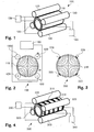
- the Figure 1 shows a three-dimensional view of a first embodiment of an ion guide chamber according to the invention.
- the Figure 2 shows a radial cross-section of the ion guide chamber 100 according to this embodiment.
- the ion guide chamber 100 comprises a tube 110 made of a resistive material, namely of doped lead silicate glass. Tubes like this are commercially available, e. g. under the name "FieldMaster TM " from Burle Electro-Optics Inc., Sturbridge MA (USA).
- the employed tube has a length of 150 mm, an outside diameter of 63.50 mm and an inside diameter of 48.26 mm.
- the resistance measured between a first axial end of the tube 110 and the opposing second axial end amounts to 100 M ⁇ .
- the employed tube features a resistive layer on its inside. Usual tubes that are commercially available feature resistive layers on their inside as well as on their outside. Therefore, if such a tube having two layers is employed the outside layer is preferably at least partially removed
- the ion guide chamber 100 further comprises four cylindrical rod electrodes 120 that are oriented in parallel to the tube 110 and that are arranged in equal angular distances from each other, surrounding the tube 110.
- the resistive regions of the two longitudinal ends of the tube 110 are connected to the opposite poles of a DC voltage generating device 140 such that a voltage U is impressed on the tube 110, accelerating charged particles injected into the tube 110.
- the Figure 3 shows a radial cross-section of a second embodiment of an ion guide chamber according to the invention.
- the ion guide chamber 200 comprises a tube 210 as described above, in connection with Figures 1 and 2 .
- the RF electrodes are constituted by conducting layers 220 applied onto the outer surface of the tube 210.
- the conducting layers representing the four electrodes are applied in a distance from each other.
- Their layout may correspond to the four-rod arrangement shown in Figure 1 , i. e. the layers may run substantially parallel to the tube axis.
- two opposite conducting layers 220 each are connected in parallel.
- the RF generating device together with the layers 220 generates an RF multi pole field penetrating through the resistive tube 210.
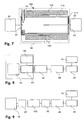
- the Figure 4 shows a three-dimensional view of a third embodiment of an ion guide chamber according to the invention. Substantially, it corresponds to the first embodiment illustrated by Figures 1 and 2 .
- the tube 310 of the ion guide chamber 300 is made from an isolating material, namely usual isolating glass.
- On the outer surface of the tube a resistive layer 311 is applied.
- the form of the layer 311 is helicoid, it extends form a first end of the tube 310 to the opposite second end, surrounding the tube 310 several times. Again, the total resistance of the layer 311 measured from one longitudinal end to the other amounts to about 100 M ⁇ .
- rod electrodes 320 are employed, fed by an RF generating device 330, where two opposite electrodes 320 each are connected in parallel.
- the two longitudinal ends of the resistive layer 311 are connected to the opposite poles of a DC voltage generating device 340.
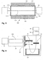
- the Figure 5 is a schematic illustration of the first embodiment of the ion guide chamber 100 employed as an interface connecting a high pressure ion source 10 to a low pressure mass analyzer 20.
- the Figure 6 is a block diagram representing the situation in Figure 5 .
- the ion guide chamber 100 Downstream of an ion source 10 an interface 30 comprising an ion guide chamber 100 is arranged downstream of an ion guide chamber 100 is arranged.
- the ion guide chamber 100 is represented in a longitudinal section running through the chamber main axis.
- the ion guide chamber 100 features a cylindrical tube 110 made of a resistive material and having the above mentioned dimensions as well as four cylindrical rod electrodes 120 that are oriented in parallel to the tube 110 and that are arranged in equal angular distances from each other, surrounding the tube 110.
- the tube 110 On its two face sides the tube 110 is provided with caps 112, 113 having small central orifices 112a, 113a.
- the rod electrodes 120 connected to an RF generating device impose a multipole RF field to the interior of the tube 110.
- the ions enter the tube 110 through the entry orifice 112a or capillary in the first cap 112 that serves as a pressure reduction stage from the source 10 to the chamber of the tube 110.
- the analyte ions are then confined to the chamber axis 114 by the RF field produced by the RF electrodes 120.
- a field along the resistive tube 110 is used for transporting the ions towards exit orifice 113a or capillary. Ions can exit the orifice 113a with better probability because they are cooled by the elevated pressure in the chamber 110 and they are contained to the axis 114 by the RF field.
- the gas pressure within the tube 110 is around 10 Pa (0.1 mbar).
- the voltage U for generating the transport field is chosen to be 100 V.
- the ions injected into to the interface 30 are fed to a time-of-flight mass spectrometer (TOFMS) 20.
- TOFMS time-of-flight mass spectrometer
- the ions are orthogonally extracted from the primary ion beam into the TOFMS 20. Accelerated by grids 22 the ions traverse the TOFMS 40, passing a reflector 23, and finally hit a detector 24.
- the detector 24 is connected to data acquisition system 25, which in turn is connected to a computer 26 for further processing of the data.
- the ion guide chamber 100 has the purpose of cooling the injected ions as well as focusing them towards the chamber axis in order to ensure that a maximum of the ions generated by the (high pressure) ion source may be fed to the (low pressure) TOFMS 20.
- an ion beam is generated by the ion source 10.
- the reaction chamber 40 receives these primary ions from the primary ion source 10, lets them react with analyte gas provided by a gas source 50 to produce analyte ions.
- the analyte molecules enter through a lateral sample inlet 41 into reaction chamber 40 and then are ionized by reactions with primary particles entering the reaction chamber 40 from the primary beam source 10 through the reaction chamber entrance 42.
- the primary beam particles may be molecules or ions, sometimes in charged or excited form.
- the primary beam may also consist of photons.
- the primary particles P then react with the analyte A in order to ionize the analyte by chemical reactions.
- the primary particles P do not react with matrix particles M in which the analyte ions A are embedded. After reacting, the analyte ions as well as the remaining primary ions are transported towards the exit 43.
- the interface 30 is designed as described above, in connection with Figure 6 , i. e. the arrangement displayed in Figure 8 comprises two ion guide chambers according to the invention, one of those used as a reaction chamber the other is part of the interface 30.
- the TOFMS 20 is connected to data acquisition system 25, which in turn is connected to a computer 26 for further processing of the data.
- the contamination is reduced by replacing the usual rings and o-rings with the tube 110 made of high resistive glass.
- a Potential U is applied along the tube 110 an ion transporting filed will be established.
- an RF field is super imposed to the ion transport field.
- the RF containment field is generated outside the glass tube 110 as described above in order to avoid contamination problems.
- the Figure 9 is a block diagram illustrating the application of the inventive ion guide chamber as an ion mobility separation device.
- the displayed arrangement features a primary beam source 10 as well as an inventive ion guide chamber 100 connected to the primary beam source 10 via an ion gate 60.
- the ion guide chamber 100 serves as an ion mobility separation device and is again connected to an interface 30 which is in turn connected to TOFMS 20, a data acquisition system 25 and a computer 26.
- the ion gate 60 arranged upsteram of the ion guide chamber 100 is operated in a pulsed manner such that the analyte ions enter the ion guide tube in a corresponding pulsed manner.
- the ion guide tube is operated at elevated pressure such that the ions injected into the ion guide tube are separated according to their collision cross section and charge state.
- the voltage applied between the entrance and the exit of the ion guide chamber is chosen to be 20 kV.
- the different ion species have different drift times in the tube.
- the inventive layout allows for creating a very homogenous transporting field which improves the performance of the ion mobility separation stage.
- the inventive device may be used as a mass filter for eliminating unwanted ion species.
- a field generating device is employed which is designed in such a way that it generates the primary confining field described above, capable of transmitting ions towards the time-of-flight mass spectrometer as well as one or several RF frequencies superimposed with said primary field.
- the incoming ions are injected into the primary confining field transmitting the ions towards the time-of-flight mass spectrometer.
- the selectivity of filtering can be adjusted by changing parameters of the excitation RF fields.
- Several additional excitation RF fields can be applied simultaneously in order to eliminate several species or several m/q ranges.
- excitation RF amplitudes may be increased in order to eliminate wider m/q ranges.
- a low mass cut-off of a suitable primary confining field is used to eliminate the corresponding low m/q range of ions.
- the invention is not restricted to the embodiments discussed above.
- the geometry of the inventive ion guide chamber as well as the electric parameters given above are subject to variation.
- the voltages indicated may be adapted to the technical function of the guide chamber (e. g. focusing/cooling, reaction, mobility separation etc.) as well as to the chamber's geometry and electric properties (in particular to the length and diameter of the chamber as well as to the total resistance).
- the ion guide chamber as an interface connecting a high pressure ion source to a low pressure mass analyzer it may be advantageous to arrange a plurality of ion guide chambers in succession, linked by capillaries, whereas the pressure is gradually reduced from one ion guide to the next one.
- the chamber as an ion mobility separation device the analyte ions may be directly generated in a pulsed manner. This saves the ion gate.
- the invention creates an ion guide chamber that is mechanically simple, cost-efficient and that allows for good transmission of analyte ions generated at elevated pressure to the mass spectrometer, undisturbed by discharges or electrode contamination, thereby ensuring high sensitivity and detection limits of the mass analysis.
Description
- The invention relates to an ion guide chamber, comprising a gas-tight elongate chamber, at least one first electrode for generating a field for transporting ions along said elongate chamber and at least one second electrode for generating a field for focusing the ions within the elongate chamber. The invention further relates to an apparatus for mass analysis comprising such an ion chamber.
- Mass spectrometry (MS) is a method of analysis that can be applied in a wide field of different applications. MS can be used for chemical and biological analysis in many different fields, including the analysis of gases, liquids, solids, plasmas, aerosols, biological aerosols, biological material, tissue, and so forth.
- Mass spectrometry involves the measurement of the mass-to-charge ratio of ions. In many applications these ions are created in high pressure ion sources. Many mass analyzing devices however require that the ions are injected into a high vacuum chamber. Therefore, it has been proposed to transfer the ions from the high pressure ion source into the high vacuum through an intermediate pressure region. Often, the ions have to pass one or several differentially pumped stages for the transfer into the high vacuum of the MS.
- It is desirable that this transfer of ions is efficient, e.g. with little loss of ions. Various methods have been used to optimize the transmission. Since the differential pumping stages often consist of one or several orifices or capillaries through which the ions have to be transferred, many of the inventions for increasing ion transmission incorporate ways to retain the ions close to the ideal ion path connecting those orifices and capillaries.
- This is often accomplished with an ion guide chamber that holds two superimposed fields. A first field is used for transport of ions through the residual gas from the entrance to the exit. For this, the field direction is essentially parallel to the chamber main axis, and the field can be static. A second electric field is applied for confining the ions close to the axis. This is often done with an RF field with low amplitudes on the chamber axis and larger amplitudes away from the axis. Such an RF field creates an effective potential confining the ions to the axis. Examples of such fields are RF multipole fields. The transport field controls the axial ion movement and directs the ions towards the exit orifice into the (next) higher vacuum, whereas the RF field confines the ions to the center axis within the chamber.
- An example of such a device is described in
US 4,963,736 (MDS Inc.) as well as in Douglas J. D. and French J.B., Collisional Cooling effects in radio frequency quadrupoles, J. Am. Soc. Mass Spectrom. 3, 398, 1992. It uses radio frequency (RF) fields, which can focus the ions along an axis and additionally can cool the ions through collisions to further increase transmission efficiencies into the mass spectrometer. The fields are generated by elongated rods that are arranged within the vacuum chambers. - Another device is described in
US 5,847,386 (MDS Inc.) and in Dodonov A., Kozlovsky V., Loboda A. Raznikov V., Sulimenkov I., Tolmachev A., Kraft A., Wollnik H., A new Technique for Decomposition of Selected Ions in Molecule Ion Reactor Coupled with Ortho-Time-of-flight Mass spectrometry, Rap. Comm. In Mass Spec., 11, 1649-1656, 1997. This device also uses an RF quadrupole but also has a superimposed linear field along the RF Quadrupole by segmenting the quadrupole. This allows to control ion energies and to decrease the residence time in the quadrupole. Again, the quadrupole rod sets are arranged within the vacuum chamber. - In still other devices the superposition of a linear field and an RF field is achieved by tilting the quadrupole electrodes towards the central axis, or by using quadrupole electrodes of tempered shape instead of cylindrical shape.
- The geometry of the prior art vacuum chambers and rods is rather complex. Furthermore, one has to make sure that contamination of the RF electrodes to the analyte gas held in the vacuum chambers, e. g. due to outgasing, does not occur. This sets high demands on the RF electrode material. Furthermore, breakdown voltages are very low at intermediate pressures as they are used within the vacuum chambers described above. Therefore, discharges may be provoked by the RF electrodes arranged within the chambers.
- It is the object of the invention to create an ion guide chamber pertaining to the technical field initially mentioned that is mechanically simple, cost-efficient and that allows for good transmission of analyte ions generated at elevated pressure to the mass spectrometer, undisturbed by discharges or electrode contamination, thereby ensuring high sensitivity and detection limits of the mass analysis.
- The solution of the invention is specified by the features of
claim 1. According to the invention the elongate chamber comprises a resistive structure extending substantially along a main axis of the chamber, whereas the first electrode, i. e. the electrode for generating the field for transporting the ions along the elongate chamber, is constituted by the resistive structure. The second electrode for generating the field for focusing the ions within the elongate chamber is arranged outside the elongate chamber. - The geometry of the invention, having the RF electrodes arranged outside the vacuum chamber, provides a mechanically simple solution. Furthermore, having the electrodes outside the glass tube has the big advantage that contamination of the RF electrodes to the analyte gas cannot occur. This allows for a cost-saving design of the RF electrodes. Furthermore, having the RF electrodes with the corresponding voltages outside the chamber, preferably at atmospheric pressure or at high vacuum, minimizes the discharge problem mentioned above.
- The transporting field controls ion energies, which allows controlling fragmentation, and decreases residence times, which is often desired in hyphenated MS techniques.
- Therefore, an apparatus for mass analysis according to the invention comprises:
- a) at least one ion guide chamber;
- b) a first voltage generating device connected to the at least one first electrode for generating the field for transporting the ions;
- c) a second voltage generating device connected to the at least one second electrode for generating the field for focussing the ions; and
- d) a mass spectrometer, in particular a time-of-flight mass spectrometer, arranged downstream of the at least one ion guide chamber.
- Several ion guide chambers may be arranged in series in order to allow for efficient ion transfer through several stages of differential pumping or to perform different functions.
- Due to the fact that the inventive ion guide chamber or each of the subsequently arranged inventive ion guide chambers, respectively, allows for decreasing the pressure the inventive device is particularly suitable for guiding ions from high pressure ion sources arranged upstream of the at least one ion guide chamber to the mass spectrometer arranged downstream of the at least one ion guide chamber.
- In one preferred embodiment the inventive ion guide is used as an ion mobility separation device. For this purpose, an ion gate may be arranged upstream of the at least one ion guide tube. The ion guide tube is operated at elevated pressure such that the ions injected into the ion guide tube are separated according to their collision cross section and charge state. The ion gate is operated in a pulsed manner such that the analyte ions enter the ion guide tube in a corresponding pulsed manner. The different ion species have different drift times in the tube. At the exit of the tube they are transferred into the mass spectrometer where their m/Q is analyzed. The chamber of this invention allows for minimal losses due to diffusion. Furthermore, the inventive layout allows for creating a very homogenous transporting field which improves the performance of the ion mobility separation stage.
- As an alternative, the analyte ions are directly generated in a pulsed manner by the ion source. This saves the upstream ion gate.
- In another embodiment the ion guide chamber is operated as an ion source, i. e. the analyte ions are formed within the ion guide chamber by photo ionization or by any other ionization techniques that can take place under elevated pressure.
- In yet another embodiment the ion guide chamber is used as a reaction chamber. For that purpose it preferably features a first inlet for analyte molecules and a second inlet for a primary particle beam. Because of the RF confinement of the primary ions, their ion density and thus numbers of reaction products are increased in the center axis of the tube. The analyte ions are mainly generated along the axis and their probability to be transferred through the exit orifice into the high vacuum is therefore high.
- The reaction chamber described above can serve different purposes. Often the sample is embedded in a much more abundant matrix that is of no interest in the analysis. For example, when analyzing air quality the major air components N2, O2 and Ar are usually of no analytical interest. In such a case it is of advantage to use selective ionization that only ionizes the trace gases of interest but not the major components. Ionizing the major components would create a vast amount of ions that could saturate the MS system and hinder the detection of the trace ions. Several selective ion sources have been developed for this reason. Among them are single photon ionization (SPI), metastable atom beam ionization (MAB), and a large variety of ionization schemes by chemical reactions where selective reactions are used to ionize the trace samples but not the matrix.
- Preferably, the elongate chamber is constituted by a glass tube, in particular of circular cross-section. The tube can be bent, which is sometimes required in order to transport ions from non-coaxial orifices or in order to minimize the flux of photons through the orifices.
- Alternatively, the cross-section of the tube is not circular, but e. g. rectangular. Instead of glass the tube may be manufactured from another material, in particular of plastic or ceramics.
- The resistive structure may be constituted by a resistive coating on the inside and/or outside of the elongate chamber, in particular in cases where the elongate chamber is made from an isolating material such as e. g. isolating glass. It is preferred to apply the coating to the outside of the elongate chamber only as this allows for using paints that are not necessarily free of outgasing. The coating can be applied on the whole surface or in the form of structures as for example a spiral extending along the tube.
- In another embodiment the invention is realized with a chamber made from a resistive material such as resistive glass, resistive plastic or resistive ceramics. This makes an additional coating unnecessary.
- In any case, applying a voltage along the tube will generate the transporting field along the tube axis. It is advantageous to use large area transport field electrodes covering a substantial part (preferably at least half) of the generated surface of the chamber as this allows for generating smooth electric fields.
- Preferably, a resistance measured along the chamber main axis, between a first end of the resistive structure and a second end of the resistive structure opposite to the first end is at least 1 MΩ, preferably at least 5 MΩ. This ensures that the field for focusing the ions generated by the second electrode arranged outside the elongate chamber may penetrate into the chamber. At the same time, reliable transport of the ions along the chamber is provided for.
- In a preferred embodiment the at least one second electrode comprises a set of elongated rods arranged substantially parallel to the elongated chamber. The rods may be conducting or semi conducting. Their cross-section may be e. g. circular or parabolic.
- Alternatively, the at least one second electrode is constituted by at least one electrically conductive or semi-conductive coated or painted surface region on an outside of the elongated chamber. Again, due to the fact that the electrode is arranged outside the chamber problems due to outgasing electrode materials are avoided. Furthermore, using a painted electrode allows for a design of the ion guide chamber that is at the same time very compact and robust. Neither is there a need for rod fixtures, nor is it necessary to adjust and/or calibrate focusing electrodes with respect to the guide chamber.
- Preferably, the field for transporting the ions runs parallel to the chamber main axis and the field for focussing the ions is an RF multipole field generating an effective potential confining the ions to a region neighboring the chamber main axis. In principle the primary confining field may also consist of a superposition of multipole fields.
- It is known that an oscillatory inhomogeneous electrical field forms a so-called effective potential which is proportional to E2, where E is the amplitude of the electrical field strength oscillations (see e. g. Landau L. D., Lifshitz E. M.: Mechanics, Pergamon Press, Oxford 1976; Gerlich, D. "Inhomogeneous Electrical Radio Frequency Fields: A Versatile Tool for the Study of Processes with Slow Ions" in: State-Selected and State-to-State lon-Molecule Reaction Dynamics, edited by C.Y.Ng and M. Baer. Advances in Chemical Physics Series, LXXXII, 1, 1992). In case of a quadrupolar RF electrical field the effective potential results in a net force on the ion towards the quadrupole axis. This force is inverse proportional to the ion mass-to-charge ratio (m/q) and directly proportional to the ion distance from the quadrupole axis. This fundamental property of the effective potential results in that an ion with a given m/q will perform slow oscillations around the quadrupole axis with a characteristic frequency which is inversely proportional to its m/q, i. e. the quadrupole field and similarly higher multipole fields are confining fields suitable for the mass filter according to the invention.
- Linear RF multipole fields that are particularly well adapted for the inventive ion guide are usually produced using co-axial rods of parabolic or circular shape. Other shapes may be used e. g. in order to approximate quadrupole fields. Preferably, a primary RF-only field is applied between opposing set of rods.
- In a particularly preferred embodiment the second field generating device is capable of generating a rotating multipole field at the at least one second electrode, in particular a rotating quadrupole field. In principle, the utilization of such fields is known, e. g. from fundamental kinetic studies (see V. V. Raznikov, I. V. Soulimenkov, V. I. Kozlovski, A. R. Pikhtelev, M. O. Raznikova, Th. Horvath, A. A. Kholomeev, Z. Zhou, H. Wollnik, A. F. Dodonov; Ion rotating motion in a gas-filled radio-frequency quadrupole ion guide as a new technique for structural and kinetic investigations of ions; Rapid Communications in Mass Spectrometry; Volume 15, ). When properly tuned, such a rotating field can result in an ion motion orbiting around the central axis. The orbit diameter is dependent on the m/Q ratio of the ions. Ions with higher m/Q will have a smaller orbit diameter and therefore a higher chance of finding the chamber exit. Low m/Q ions will have a larger orbit diameter and therefore will no longer be able to exit the chamber and therefore their transmission to the MS is decreased. This method requires elevated gas pressures where the ion oscillations are strongly damped by gas collisions.
- Operating the RF field in a rotating mode as described above allows to increase the transfer rate of high m/Q analyte ions which stay closer to the chamber axis, while keeping the low m/Q primary ions on higher orbits and thereby reducing their ability to exit the chamber. This will minimize saturation effects in the mass analyzer due to abundant primary ions.
- In another embodiment of the invention, the second field generating device is capable of generating an additional excitation RF field to be super-positioned to a confining RF field.
- In this case, the ion guide tube is operated at lower pressure and the second field generating device is preferably designed in such a way that the superimposed RF frequency is generated such that ions belonging to one or several narrow bands of m/Q are exited onto an orbit around the center axis. This will hinder their exiting the exit orifice. For this purpose, one or several additional small amplitude RF fields are superimposed to the primary RF field. The frequencies of the additional fields must be adjusted to the characteristic oscillation frequencies of the ions to be eliminated in the primary RF field. The ions with the corresponding m/q will be gradually resonantly excited by the low amplitude RF fields. Again, a rotating multipole field is preferable because it will bring the ions into an orbit around the chamber axis.
- Especially when the device is used as an ion source or as a reaction chamber it is sometimes desirable to discriminate certain ranges of m/Q ions.
- Ions in a RF field will do fast oscillations in the frequency of the confining RF field. High m/Q ions will have lower amplitudes for these fast oscillations. This can be used to increase the density of high m/Q ions on the chamber axis relative to the density of low m/Q ions. This also holds at elevated pressures where ion oscillations are damped by gas collisions. Simillarly, it is possible to use the low m/Q cut-off of RF-only multipole fields to hinder low m/Q ions exiting the chamber.
- Other advantageous embodiments and combinations of features come out from the detailed description below and the totality of the claims.
- The drawings used to explain the embodiments show:
- Fig. 1
- A three-dimensional view of a first embodiment of an ion guide chamber according to the invention;
- Fig. 2
- a radial cross-section of the ion guide chamber according to the first embodiment;
- Fig. 3
- a radial cross-section of a second embodiment of an ion guide chamber according to the invention;
- Fig. 4
- a three-dimensional view of a third embodiment of an ion guide chamber according to the invention;
- Fig. 5
- a schematic illustration of the first embodiment of the ion guide chamber employed as an interface connecting a high pressure ion source to a low pressure mass analyzer;
- Fig. 6
- a block diagram representing the situation in
Fig. 5 ; - Fig. 7
- a schematic illustration of the first embodiment of the ion guide chamber employed as a reaction chamber;
- Fig. 8
- a block diagram representing the situation in
Fig. 7 ; and - Fig. 9
- a block diagram illustrating the application of the inventive ion guide chamber as an ion mobility separation device.
- In the figures, the same components are given the same reference symbols.
- The
Figure 1 shows a three-dimensional view of a first embodiment of an ion guide chamber according to the invention. TheFigure 2 shows a radial cross-section of theion guide chamber 100 according to this embodiment. Theion guide chamber 100 comprises atube 110 made of a resistive material, namely of doped lead silicate glass. Tubes like this are commercially available, e. g. under the name "FieldMaster™" from Burle Electro-Optics Inc., Sturbridge MA (USA). The employed tube has a length of 150 mm, an outside diameter of 63.50 mm and an inside diameter of 48.26 mm. The resistance measured between a first axial end of thetube 110 and the opposing second axial end amounts to 100 MΩ. The employed tube features a resistive layer on its inside. Usual tubes that are commercially available feature resistive layers on their inside as well as on their outside. Therefore, if such a tube having two layers is employed the outside layer is preferably at least partially removed. - The
ion guide chamber 100 further comprises fourcylindrical rod electrodes 120 that are oriented in parallel to thetube 110 and that are arranged in equal angular distances from each other, surrounding thetube 110. The fourrod electrodes 120 are fed by anRF generating device 130, where twoopposite electrodes 120 each are connected in parallel. Between neighboring electrodes an RF-only voltage
- is connected, provided by the
RF generating device 130. Thereby theRF generating device 130 together with therod electrodes 120 generates an RF multi pole field. Suprisingly, tests have shown that this RF field penetrates through theresistive tube 110 and is therefore present inside thetube 110, as diagrammatically indicated inFigure 2 . The RF multi pole field is used for focusing of ions in thecenter axis 114 of the chamber. The oscillatory inhomogeneous electrical field forms an effective potential which is proportional to E2, where E is the amplitude of the electrical field strength oscillations. - The resistive regions of the two longitudinal ends of the
tube 110 are connected to the opposite poles of a DCvoltage generating device 140 such that a voltage U is impressed on thetube 110, accelerating charged particles injected into thetube 110. - The
Figure 3 shows a radial cross-section of a second embodiment of an ion guide chamber according to the invention. Again, theion guide chamber 200 comprises atube 210 as described above, in connection withFigures 1 and 2 . In contrast to the first embodiment the RF electrodes are constituted by conductinglayers 220 applied onto the outer surface of thetube 210. The conducting layers representing the four electrodes are applied in a distance from each other. Their layout may correspond to the four-rod arrangement shown inFigure 1 , i. e. the layers may run substantially parallel to the tube axis. Again, two opposite conductinglayers 220 each are connected in parallel. The RF generating device together with thelayers 220 generates an RF multi pole field penetrating through theresistive tube 210. - The
Figure 4 shows a three-dimensional view of a third embodiment of an ion guide chamber according to the invention. Substantially, it corresponds to the first embodiment illustrated byFigures 1 and 2 . In contrast to that embodiment, however, thetube 310 of theion guide chamber 300 is made from an isolating material, namely usual isolating glass. On the outer surface of the tube aresistive layer 311 is applied. The form of thelayer 311 is helicoid, it extends form a first end of thetube 310 to the opposite second end, surrounding thetube 310 several times. Again, the total resistance of thelayer 311 measured from one longitudinal end to the other amounts to about 100 MΩ. - Again, four
rod electrodes 320 are employed, fed by anRF generating device 330, where twoopposite electrodes 320 each are connected in parallel. The two longitudinal ends of theresistive layer 311 are connected to the opposite poles of a DCvoltage generating device 340. - The
Figure 5 is a schematic illustration of the first embodiment of theion guide chamber 100 employed as an interface connecting a highpressure ion source 10 to a lowpressure mass analyzer 20. TheFigure 6 is a block diagram representing the situation inFigure 5 . - Downstream of an
ion source 10 aninterface 30 comprising anion guide chamber 100 is arranged. InFigure 5 , theion guide chamber 100 is represented in a longitudinal section running through the chamber main axis. As displayed inFigures 1, 2 theion guide chamber 100 features acylindrical tube 110 made of a resistive material and having the above mentioned dimensions as well as fourcylindrical rod electrodes 120 that are oriented in parallel to thetube 110 and that are arranged in equal angular distances from each other, surrounding thetube 110. On its two face sides thetube 110 is provided withcaps central orifices rod electrodes 120 connected to an RF generating device impose a multipole RF field to the interior of thetube 110. - The ions enter the
tube 110 through theentry orifice 112a or capillary in thefirst cap 112 that serves as a pressure reduction stage from thesource 10 to the chamber of thetube 110. The analyte ions are then confined to thechamber axis 114 by the RF field produced by theRF electrodes 120. At the same time, a field along theresistive tube 110 is used for transporting the ions towardsexit orifice 113a or capillary. Ions can exit theorifice 113a with better probability because they are cooled by the elevated pressure in thechamber 110 and they are contained to theaxis 114 by the RF field. The gas pressure within thetube 110 is around 10 Pa (0.1 mbar). The voltage U for generating the transport field is chosen to be 100 V. - The ions injected into to the
interface 30 are fed to a time-of-flight mass spectrometer (TOFMS) 20. In anextraction chamber 21 of the TOFMS the ions are orthogonally extracted from the primary ion beam into theTOFMS 20. Accelerated bygrids 22 the ions traverse theTOFMS 40, passing areflector 23, and finally hit adetector 24. Thedetector 24 is connected todata acquisition system 25, which in turn is connected to acomputer 26 for further processing of the data. - In this arrangement, the
ion guide chamber 100 has the purpose of cooling the injected ions as well as focusing them towards the chamber axis in order to ensure that a maximum of the ions generated by the (high pressure) ion source may be fed to the (low pressure) TOFMS 20. - The
Figure 7 is a schematic illustration of the first embodiment of the ion guide chamber employed as a reaction chamber. TheFigure 8 is a block diagram representing the situation inFig. 7 . - Under elevated pressure, an ion beam is generated by the
ion source 10. Thereaction chamber 40 receives these primary ions from theprimary ion source 10, lets them react with analyte gas provided by agas source 50 to produce analyte ions. For this purpose, the analyte molecules enter through alateral sample inlet 41 intoreaction chamber 40 and then are ionized by reactions with primary particles entering thereaction chamber 40 from theprimary beam source 10 through thereaction chamber entrance 42. The primary beam particles may be molecules or ions, sometimes in charged or excited form. The primary beam may also consist of photons. The primary particles P then react with the analyte A in order to ionize the analyte by chemical reactions. The primary particles P do not react with matrix particles M in which the analyte ions A are embedded. After reacting, the analyte ions as well as the remaining primary ions are transported towards theexit 43. - Afterwards, these ions are transported through the
differential pumping interface 30 towards the low-pressure TOFMS 20. The transport field is generated by an applied voltage of about 1 kV. Varying this voltage allows for controlling the reaction process: If the voltage is increased the generation of water clusters is inhibited. Preferably, theinterface 30 is designed as described above, in connection withFigure 6 , i. e. the arrangement displayed inFigure 8 comprises two ion guide chambers according to the invention, one of those used as a reaction chamber the other is part of theinterface 30. Again, theTOFMS 20 is connected todata acquisition system 25, which in turn is connected to acomputer 26 for further processing of the data. - In prior art solutions, there are two problems that can limit the sensitivity of this method: Firstly, not all analyte ions A may find the exit due to their diffusion in the gas. This diffusion will statistically move the ions off the reactor chamber axis and thereby they will hit the exit electrode instead of the exit orifice. Furthermore, contaminates C can either leak into the chamber or they can desorb from chamber wall material like o-rings or electrode rings.
- In the embodiment according to the invention the contamination is reduced by replacing the usual rings and o-rings with the
tube 110 made of high resistive glass. When a Potential U is applied along thetube 110 an ion transporting filed will be established. To increase the transmission of ions through theexit orifice 43 or exit capillary (not shown) or exit matrix (not shown) an RF field is super imposed to the ion transport field. The RF containment field is generated outside theglass tube 110 as described above in order to avoid contamination problems. - The
Figure 9 is a block diagram illustrating the application of the inventive ion guide chamber as an ion mobility separation device. The displayed arrangement features aprimary beam source 10 as well as an inventiveion guide chamber 100 connected to theprimary beam source 10 via anion gate 60. Theion guide chamber 100 serves as an ion mobility separation device and is again connected to aninterface 30 which is in turn connected to TOFMS 20, adata acquisition system 25 and acomputer 26. - The
ion gate 60 arranged upsteram of theion guide chamber 100 is operated in a pulsed manner such that the analyte ions enter the ion guide tube in a corresponding pulsed manner. The ion guide tube is operated at elevated pressure such that the ions injected into the ion guide tube are separated according to their collision cross section and charge state. The voltage applied between the entrance and the exit of the ion guide chamber is chosen to be 20 kV. The different ion species have different drift times in the tube. At the exit of the tube they are transferred into the mass spectrometer where their m/Q is analyzed. Due to the RF focusing field the chamber of this invention allows for minimal losses due to diffusion. Furthermore, the inventive layout allows for creating a very homogenous transporting field which improves the performance of the ion mobility separation stage. - Furthermore, the inventive device may be used as a mass filter for eliminating unwanted ion species. In this operation mode a field generating device is employed which is designed in such a way that it generates the primary confining field described above, capable of transmitting ions towards the time-of-flight mass spectrometer as well as one or several RF frequencies superimposed with said primary field. These RF frequencies match oscillation frequencies of ions belonging to one or several narrow bands of m/q (i. e. preferably A(m/q) = 1 or 2). The incoming ions are injected into the primary confining field transmitting the ions towards the time-of-flight mass spectrometer. Ions belonging to said narrow bands of m/q are resonantly excited and finally ejected from a confining area of the primary field. Accordingly, only the desired ions that do not belong to the narrow bands of m/q reach the time-of-flight mass spectrometer coupled to the mass filter. The process is described in more detail in the European Patent Application No.
06 405 519.7 of 14 December 2006 - The selectivity of filtering can be adjusted by changing parameters of the excitation RF fields. Several additional excitation RF fields can be applied simultaneously in order to eliminate several species or several m/q ranges. Furthermore, excitation RF amplitudes may be increased in order to eliminate wider m/q ranges.
- Alternatively, if the ion species to be filtered out is of a lower mass than all the interesting species being generated by the ion source, a low mass cut-off of a suitable primary confining field is used to eliminate the corresponding low m/q range of ions.
- The invention is not restricted to the embodiments discussed above. In particular the geometry of the inventive ion guide chamber as well as the electric parameters given above are subject to variation. For example, the voltages indicated may be adapted to the technical function of the guide chamber (e. g. focusing/cooling, reaction, mobility separation etc.) as well as to the chamber's geometry and electric properties (in particular to the length and diameter of the chamber as well as to the total resistance).
- In the case of using the ion guide chamber as an interface connecting a high pressure ion source to a low pressure mass analyzer it may be advantageous to arrange a plurality of ion guide chambers in succession, linked by capillaries, whereas the pressure is gradually reduced from one ion guide to the next one. In the case of using the chamber as an ion mobility separation device the analyte ions may be directly generated in a pulsed manner. This saves the ion gate.
- In summary, it is to be noted that the invention creates an ion guide chamber that is mechanically simple, cost-efficient and that allows for good transmission of analyte ions generated at elevated pressure to the mass spectrometer, undisturbed by discharges or electrode contamination, thereby ensuring high sensitivity and detection limits of the mass analysis.
Claims (16)
- An ion guide chamber, comprisinga) a gas-tight elongate chamber (100; 200; 300);b) at least one first electrode for generating a field for transporting ions along the elongate chamber (100; 200; 300);c) at least one second electrode (120; 220; 320) for generating a field for focusing
the ions within the elongate chamber (100; 200; 300);
characterized in thatd) the elongate chamber (100; 200; 300) comprises a resistive structure extending substantially along a main axis of the chamber (100; 200; 300), wherein the first electrode is constituted by the resistive structure; and in thate) the second electrode (120; 220; 320) is arranged outside the elongate chamber (100; 200; 300). - The ion guide chamber as recited in claim 1, characterized in that the elongate chamber (100; 200; 300) is constituted by a glass tube, in particular of circular cross-section.
- The ion guide chamber as recited in claim 1 or 2, characterized in that the resistive structure is constituted by a resistive coating on the inside and/or outside of the elongate chamber.
- The ion guide chamber as recited in claim 1 or 2, characterized in that the elongate chamber is built from a resistive material.
- The ion guide chamber as recited in any of claims 1 to 4, characterized in that a resistance measured along the chamber main axis, between a first end of the resistive structure and a second end of the resistive structure opposite to the first end is at least 1 MΩ, preferably at least 5 MΩ.
- The ion guide chamber as recited in any of claims 1 to 5, characterized in that the at least one second electrode comprises a set of elongated rods (120; 320) arranged substantially parallel to the elongated chamber (100; 300).
- The ion guide chamber as recited in any of claims 1 to 6, characterized in that the at least one second electrode is constituted by at least one electrically conductive or semi-conductive coated or painted surface region (220) on an outside of the elongated chamber (200).
- The ion guide chamber as recited in any of claims 1 to 7, characterized in that the field for transporting the ions runs parallel to the chamber main axis and in that the field for focussing the ions is a RF multipole field generating an effective potential confining the ions to a region neighboring the chamber main axis.
- The ion guide chamber as recited in any of claims 1 to 8, characterized by a first inlet (41) for analyte molecules and by a second inlet (42) for a primary particle beam.
- An apparatus for mass analysis comprising:a) at least one ion guide chamber (100; 200; 300) as recited in any of claims 1 to 9;b) a first voltage generating device (140; 340) connected to the at least one first electrode for generating the field for transporting the ions;c) a second voltage generating device (130; 330) connected to the at least one second electrode (120; 320) for generating the field for focussing the ions; andd) a mass spectrometer (20), in particular a time-of-flight mass spectrometer, arranged downstream of the at least one ion guide chamber (100; 200; 300).
- The apparatus as recited in claim 10, further comprising a high pressure ion source (10) arranged upstream of the at least one ion guide chamber (100; 200; 300).
- The apparatus as recited in claim 11, characterized in that an ion gate (60) is arranged upstream of the at least one ion guide tube (100) and in that the ion guide tube (100) is operated at elevated pressure such that the ions injected into the ion guide tube (100) are separated according to their collision cross section and charge state.
- The apparatus as recited in claim 10, characterized in that the ion guide chamber is operated as an ion source.
- The apparatus as recited in one of claims 10 to 13, characterized in that the second field generating device is capable of generating a rotating multipole field at the at least one second electrode.
- The apparatus as recited in one of claims 10 to 14, characterized in that the second field generating device is capable of generating an additional excitation RF field to be super-positioned to a confining RF field.
- The apparatus as recited in claim 15, characterized in that the second field generating device is designed in such a way that the superimposed RF frequency is generated such that ions belonging to one or several narrow bands of m/Q are exited onto an orbit around the center axis.
Priority Applications (2)
| Application Number | Priority Date | Filing Date | Title |
|---|---|---|---|
| EP07405077.4A EP1968100B1 (en) | 2007-03-08 | 2007-03-08 | Ion guide chamber |
| US12/044,059 US7935922B2 (en) | 2007-03-08 | 2008-03-07 | Ion guide chamber |
Applications Claiming Priority (1)
| Application Number | Priority Date | Filing Date | Title |
|---|---|---|---|
| EP07405077.4A EP1968100B1 (en) | 2007-03-08 | 2007-03-08 | Ion guide chamber |
Publications (2)
| Publication Number | Publication Date |
|---|---|
| EP1968100A1 EP1968100A1 (en) | 2008-09-10 |
| EP1968100B1 true EP1968100B1 (en) | 2014-04-30 |
Family
ID=38261522
Family Applications (1)
| Application Number | Title | Priority Date | Filing Date |
|---|---|---|---|
| EP07405077.4A Active EP1968100B1 (en) | 2007-03-08 | 2007-03-08 | Ion guide chamber |
Country Status (2)
| Country | Link |
|---|---|
| US (1) | US7935922B2 (en) |
| EP (1) | EP1968100B1 (en) |
Families Citing this family (5)
| Publication number | Priority date | Publication date | Assignee | Title |
|---|---|---|---|---|
| US8124930B2 (en) * | 2009-06-05 | 2012-02-28 | Agilent Technologies, Inc. | Multipole ion transport apparatus and related methods |
| WO2017033251A1 (en) * | 2015-08-24 | 2017-03-02 | 株式会社島津製作所 | Ion-mobility spectrometry drift cell and ion-mobility spectrometer |
| US9842730B2 (en) | 2015-12-08 | 2017-12-12 | Thermo Finnigan Llc | Methods for tandem collision-induced dissociation cells |
| EP3474311A1 (en) | 2017-10-20 | 2019-04-24 | Tofwerk AG | Ion molecule reactor |
| WO2020076727A1 (en) | 2018-10-07 | 2020-04-16 | Horne Tanner L | Nuclear fusion reactor with toroidal superconducting magnetic coils implementing inertial electrostatic heating |
Citations (1)
| Publication number | Priority date | Publication date | Assignee | Title |
|---|---|---|---|---|
| US5847386A (en) * | 1995-08-11 | 1998-12-08 | Mds Inc. | Spectrometer with axial field |
Family Cites Families (18)
| Publication number | Priority date | Publication date | Assignee | Title |
|---|---|---|---|---|
| CA1307859C (en) | 1988-12-12 | 1992-09-22 | Donald James Douglas | Mass spectrometer and method with improved ion transmission |
| US5248882A (en) | 1992-05-28 | 1993-09-28 | Extrel Ftms, Inc. | Method and apparatus for providing tailored excitation as in Fourier transform mass spectrometry |
| DE69536105D1 (en) | 1995-07-03 | 2010-10-28 | Hitachi Ltd | MASS SPECTROMETRY |
| US5598001A (en) | 1996-01-30 | 1997-01-28 | Hewlett-Packard Company | Mass selective multinotch filter with orthogonal excision fields |
| US6140638A (en) | 1997-06-04 | 2000-10-31 | Mds Inc. | Bandpass reactive collision cell |
| US6593570B2 (en) * | 2000-05-24 | 2003-07-15 | Agilent Technologies, Inc. | Ion optic components for mass spectrometers |
| GB2364168B (en) | 2000-06-09 | 2002-06-26 | Micromass Ltd | Methods and apparatus for mass spectrometry |
| US6627912B2 (en) | 2001-05-14 | 2003-09-30 | Mds Inc. | Method of operating a mass spectrometer to suppress unwanted ions |
| GB2389452B (en) * | 2001-12-06 | 2006-05-10 | Bruker Daltonik Gmbh | Ion-guide |
| US7034292B1 (en) * | 2002-05-31 | 2006-04-25 | Analytica Of Branford, Inc. | Mass spectrometry with segmented RF multiple ion guides in various pressure regions |
| US7309861B2 (en) * | 2002-09-03 | 2007-12-18 | Micromass Uk Limited | Mass spectrometer |
| US6900431B2 (en) | 2003-03-21 | 2005-05-31 | Predicant Biosciences, Inc. | Multiplexed orthogonal time-of-flight mass spectrometer |
| US6800851B1 (en) * | 2003-08-20 | 2004-10-05 | Bruker Daltonik Gmbh | Electron-ion fragmentation reactions in multipolar radiofrequency fields |
| US7081618B2 (en) * | 2004-03-24 | 2006-07-25 | Burle Technologies, Inc. | Use of conductive glass tubes to create electric fields in ion mobility spectrometers |
| CN1326191C (en) * | 2004-06-04 | 2007-07-11 | 复旦大学 | Ion trap quality analyzer constructed with printed circuit board |
| US7064322B2 (en) | 2004-10-01 | 2006-06-20 | Agilent Technologies, Inc. | Mass spectrometer multipole device |
| EP1933365A1 (en) | 2006-12-14 | 2008-06-18 | Tofwerk AG | Apparatus for mass analysis of ions |
| EP1933366B1 (en) | 2006-12-14 | 2019-06-12 | Tofwerk AG | Apparatus for mass analysis of ions |
-
2007
- 2007-03-08 EP EP07405077.4A patent/EP1968100B1/en active Active
-
2008
- 2008-03-07 US US12/044,059 patent/US7935922B2/en active Active
Patent Citations (1)
| Publication number | Priority date | Publication date | Assignee | Title |
|---|---|---|---|---|
| US5847386A (en) * | 1995-08-11 | 1998-12-08 | Mds Inc. | Spectrometer with axial field |
Also Published As
| Publication number | Publication date |
|---|---|
| US20080217528A1 (en) | 2008-09-11 |
| US7935922B2 (en) | 2011-05-03 |
| EP1968100A1 (en) | 2008-09-10 |
Similar Documents
| Publication | Publication Date | Title |
|---|---|---|
| Kelly et al. | The ion funnel: theory, implementations, and applications | |
| US6559444B2 (en) | Tandem mass spectrometer comprising only two quadrupole filters | |
| US8299421B2 (en) | Low-pressure electron ionization and chemical ionization for mass spectrometry | |
| US7932488B2 (en) | Concentrating mass spectrometer ion guide, spectrometer and method | |
| US6222185B1 (en) | Plasma mass spectrometer | |
| EP1704578B1 (en) | Ion extraction devices and methods of selectively extracting ions | |
| EP3038134A1 (en) | Multipole ion guides utilizing segmented and helical electrodes, and related systems and methods | |
| EP1933365A1 (en) | Apparatus for mass analysis of ions | |
| US20070084998A1 (en) | Novel tandem mass spectrometer | |
| EP2973650B1 (en) | Miniature charged particle trap with elongated trapping region for mass spectrometry | |
| EP1568063A2 (en) | Processes for designing mass separators and ion traps, methods for producing mass separators and ion traps. mass spectrometers, ion traps, and methods for analysing samples | |
| CN110186990B (en) | Tandem ion mobility spectrometer | |
| EP2858091A1 (en) | Method and apparatus for a combined linear ion trap and quadrupole mass filter | |
| EP1592042A2 (en) | Unevenly segmented multipole | |
| EP3179501B1 (en) | Method and apparatus for tandem collison - induced dissociation cells | |
| US11195710B2 (en) | Hybrid mass spectrometric system | |
| US20120286150A1 (en) | Method and apparatus for transmitting ions in a mass spectrometer maintained in a sub-atmospheric pressure regime | |
| EP1968100B1 (en) | Ion guide chamber | |
| EP2795663B1 (en) | Improvements in or relating to mass spectrometry | |
| EP3889595A1 (en) | Counterflow uniform-field ion mobility spectrometer | |
| US9536723B1 (en) | Thin field terminator for linear quadrupole ion guides, and related systems and methods | |
| EP4170696A1 (en) | Ion activation and fragmentation in sub-ambient pressure for ion mobility and mass spectrometry | |
| CN115346854A (en) | Mass spectrometer | |
| CN115112746A (en) | Laterally extended trapped ion mobility spectrometer |
Legal Events
| Date | Code | Title | Description |
|---|---|---|---|
| PUAI | Public reference made under article 153(3) epc to a published international application that has entered the european phase |
Free format text: ORIGINAL CODE: 0009012 |
|
| AK | Designated contracting states |
Kind code of ref document: A1 Designated state(s): AT BE BG CH CY CZ DE DK EE ES FI FR GB GR HU IE IS IT LI LT LU LV MC MT NL PL PT RO SE SI SK TR |
|
| AX | Request for extension of the european patent |
Extension state: AL BA HR MK RS |
|
| 17P | Request for examination filed |
Effective date: 20090109 |
|
| AKX | Designation fees paid |
Designated state(s): CH DE FR GB LI |
|
| GRAP | Despatch of communication of intention to grant a patent |
Free format text: ORIGINAL CODE: EPIDOSNIGR1 |
|
| INTG | Intention to grant announced |
Effective date: 20130924 |
|
| GRAS | Grant fee paid |
Free format text: ORIGINAL CODE: EPIDOSNIGR3 |
|
| RIN1 | Information on inventor provided before grant (corrected) |
Inventor name: GONIN, MARC Inventor name: FUHRER, KATRIN |
|
| RAP1 | Party data changed (applicant data changed or rights of an application transferred) |
Owner name: TOFWERK AG |
|
| GRAA | (expected) grant |
Free format text: ORIGINAL CODE: 0009210 |
|
| AK | Designated contracting states |
Kind code of ref document: B1 Designated state(s): CH DE FR GB LI |
|
| REG | Reference to a national code |
Ref country code: GB Ref legal event code: FG4D Ref country code: CH Ref legal event code: EP |
|
| REG | Reference to a national code |
Ref country code: DE Ref legal event code: R096 Ref document number: 602007036343 Country of ref document: DE Effective date: 20140612 |
|
| REG | Reference to a national code |
Ref country code: CH Ref legal event code: NV Representative=s name: KELLER AND PARTNER PATENTANWAELTE AG, CH |
|
| REG | Reference to a national code |
Ref country code: DE Ref legal event code: R097 Ref document number: 602007036343 Country of ref document: DE |
|
| REG | Reference to a national code |
Ref country code: FR Ref legal event code: PLFP Year of fee payment: 9 |
|
| PLBE | No opposition filed within time limit |
Free format text: ORIGINAL CODE: 0009261 |
|
| STAA | Information on the status of an ep patent application or granted ep patent |
Free format text: STATUS: NO OPPOSITION FILED WITHIN TIME LIMIT |
|
| REG | Reference to a national code |
Ref country code: CH Ref legal event code: PCAR Free format text: NEW ADDRESS: EIGERSTRASSE 2 POSTFACH, 3000 BERN 14 (CH) |
|
| 26N | No opposition filed |
Effective date: 20150202 |
|
| REG | Reference to a national code |
Ref country code: DE Ref legal event code: R097 Ref document number: 602007036343 Country of ref document: DE Effective date: 20150202 |
|
| REG | Reference to a national code |
Ref country code: FR Ref legal event code: PLFP Year of fee payment: 10 |
|
| REG | Reference to a national code |
Ref country code: FR Ref legal event code: PLFP Year of fee payment: 11 |
|
| REG | Reference to a national code |
Ref country code: FR Ref legal event code: PLFP Year of fee payment: 12 |
|
| REG | Reference to a national code |
Ref country code: CH Ref legal event code: PFA Owner name: TOFWERK AG, CH Free format text: FORMER OWNER: TOFWERK AG, CH |
|
| PGFP | Annual fee paid to national office [announced via postgrant information from national office to epo] |
Ref country code: FR Payment date: 20230327 Year of fee payment: 17 |
|
| PGFP | Annual fee paid to national office [announced via postgrant information from national office to epo] |
Ref country code: GB Payment date: 20230321 Year of fee payment: 17 Ref country code: DE Payment date: 20230224 Year of fee payment: 17 |
|
| PGFP | Annual fee paid to national office [announced via postgrant information from national office to epo] |
Ref country code: CH Payment date: 20230402 Year of fee payment: 17 |