EP1967874A1 - Backlight module - Google Patents
Backlight module Download PDFInfo
- Publication number
- EP1967874A1 EP1967874A1 EP07015206A EP07015206A EP1967874A1 EP 1967874 A1 EP1967874 A1 EP 1967874A1 EP 07015206 A EP07015206 A EP 07015206A EP 07015206 A EP07015206 A EP 07015206A EP 1967874 A1 EP1967874 A1 EP 1967874A1
- Authority
- EP
- European Patent Office
- Prior art keywords
- light source
- source set
- light
- backlight
- brightness
- Prior art date
- Legal status (The legal status is an assumption and is not a legal conclusion. Google has not performed a legal analysis and makes no representation as to the accuracy of the status listed.)
- Withdrawn
Links
- 230000007423 decrease Effects 0.000 claims description 3
- 238000000034 method Methods 0.000 description 8
- 238000010586 diagram Methods 0.000 description 5
- 230000008901 benefit Effects 0.000 description 4
- 238000012986 modification Methods 0.000 description 2
- 230000004048 modification Effects 0.000 description 2
- 238000009825 accumulation Methods 0.000 description 1
- 230000003247 decreasing effect Effects 0.000 description 1
- 230000002035 prolonged effect Effects 0.000 description 1
- 239000000758 substrate Substances 0.000 description 1
Images



Classifications
-
- G—PHYSICS
- G02—OPTICS
- G02B—OPTICAL ELEMENTS, SYSTEMS OR APPARATUS
- G02B6/00—Light guides; Structural details of arrangements comprising light guides and other optical elements, e.g. couplings
- G02B6/0001—Light guides; Structural details of arrangements comprising light guides and other optical elements, e.g. couplings specially adapted for lighting devices or systems
- G02B6/0011—Light guides; Structural details of arrangements comprising light guides and other optical elements, e.g. couplings specially adapted for lighting devices or systems the light guides being planar or of plate-like form
- G02B6/0066—Light guides; Structural details of arrangements comprising light guides and other optical elements, e.g. couplings specially adapted for lighting devices or systems the light guides being planar or of plate-like form characterised by the light source being coupled to the light guide
- G02B6/0068—Arrangements of plural sources, e.g. multi-colour light sources
Definitions
- Taiwan application serial no. 95111501 filed March 31, 2006 . All disclosure of the Taiwan application is incorporated herein by reference.
- the present invention relates to a backlight module, and particularly to a backlight module having a longer lifetime.
- a conventional backlight module 9 includes a plurality of light sources 91, a backlight driving unit 92 and a power supply unit 93.
- the light sources 91 are cold cathode fluorescent lamp (CCFL) tubes, and the backlight driving unit 92 is coupled between the power supply unit 93 and the light sources 91.
- CCFL cold cathode fluorescent lamp
- the power supply unit 93 provides power and drives the light sources 91 in conjunction with the backlight driving unit 92. Then, the light emitted from the light sources 91 is projected onto a display panel (now shown), thus generating enough displaying brightness.
- the brightness of the light sources may decrease with time.
- a light source is considered as not suitable for use when its brightness is decreased to a value of 50% of the maximum brightness thereof. Therefore, it is currently an important issue to extend the lifetime of the backlight module.
- One of the conventional solutions is to lower the current of the light sources. However, this may lower the brightness and the light adjustment range thereof.
- Another conventional solution is to increase the number of the light sources. However, more the number of light sources generate more heat, and heat accumulation may also decrease the lifetimes of other components around the light sources.
- the present invention provides a backlight module to increase the lifetime of the backlight module.
- the backlight module of the present invention includes a control unit, a backlight driving unit, a first light source set, and a second light source set.
- the control unit is adapted for controlling and coordinating the each component.
- the backlight driving unit is electrically connected to and controlled by the control unit to generate a driving command.
- the first light source set is electrically connected to and controlled by the backlight driving unit to light on/off.
- the second light source set is electrically connected to and controlled by the backlight driving unit to light on/off.
- the control unit controls the backlight driving unit to generate the driving command according to a predetermined value to drive the first and the second light source sets by turns for achieving a longer lifetime.
- the backlight module includes a control unit, a backlight driving unit, a first light source set, and a second light source set.
- the control unit is adapted for controlling and coordinating the other components.
- the backlight driving unit is electrically connected to and controlled by the control unit to generate a driving command instructing the light source sets to power on/off.
- the first light source set is electrically connected to and controlled by the backlight driving unit to light on/off.
- the second light source set is electrically connected to and controlled by the backlight driving unit to light on/off.
- the backlight driving unit drives the first light source set, and the control unit determines whether to light on the second light source set or not according to a predetermined value simultaneouly, in order to compensate a brightness loss of the first light source set, thus maintaining a brightness of the backlight module within a predetermined range.
- Fig. 1 is a circuit block diagram showing a conventional direct type LCD device.
- Fig. 2 is a circuit block diagram showing the backlight module according to the first and third embodiment of the present invention.
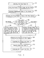
- Fig. 3 is a flow chart showing the control method of the first preferred embodiment.
- Fig. 4 is a circuit block diagram showing the backlight module according to the second embodiment of the present invention.
- Fig. 5 is a flow chart showing the control method of the second embodiment.
- Fig. 6 is a graph illustrating the third embodiment according to the present invention of the backlight module having a longer lifetime, which employs an output brightness of a second light source set to compensate a brightness loss of a first light source set, so as to maintain the light sources within a predetermined range.
- Fig. 7 is schematic diagram illustrating the third embodiment, in which the first light source set is not co-planar with the second light source set, and a substrate on which the first and the second light source sets are assembled can be adjusted in corporation with the space of the second light source set.
- Fig. 8 is a flow chart showing the control method of the third embodiment.
- Fig. 9 is a circuit block diagram showing the backlight module according to the fourth embodiment of the present invention.
- Fig. 10 is a flow chart showing the control method of the fourth embodiment.
- Driving Light Source Sets by Turns According to Predetermined Time Interval
- a backlight module 100 includes a control unit 12, a power supply unit 10, an input unit 14, a memory unit 13, a backlight driving unit 11, a first light source set 151, and a second light source set 152.
- the control unit 12 is connected to the power supply unit 10, the backlight driving unit 11, a memory unit 13, and the input unit 14.
- the control unit 12 includes a timer 121 for timing the period of power supply provided by the power supplying unit 10.
- the power supplying unit 10 is adapted for supplying power to the backlight driving unit 11.
- the backlight driving unit 11 is electrically connected to the power supply unit 10, the control unit 12, the first light source set 151 and the second light source set 152.
- the backlight driving unit 11 is controlled by the control unit 12 to generate a driving command to light on/off the first light source set 151 and the second light source set 152.
- the backlight driving unit 11 may be composed of a plurality of backlight drivers for driving the first light source 151 and the second light source set 152, respectively.
- the first and the second light source sets 151, 152 are both electrically connected to the backlight driving unit 11, and are turned on/off by turns according to the driving command.
- Each light source set includes a plurality of light sources, which may be cold cathode fluorescent lamps (CCFL), or light emitting diodes (LED).
- the first and the second light sources 151, 152 can be disposed at a bottom or a side of a display panel (not shown) according to the type of the backlight module, e.g., direct type backlight or side
- the input unit 14 serving as an interface for users to input a predetermined value of a time interval t and the predetermined value is stored in the memory unit 13 by the control unit 12.
- the time interval t is a predetermined value, and is not limited to be inputted from the input unit 14, while it can also be a default value of a system of the backlight module.
- the first light source set 151 and the second light source set 152 are lighted on by turns according to the time interval t.
- the control unit 12 detects a first-time power on (step 301), and then the timer 121 starts to time the period of power supplying (step 302).
- a predetermined value of the time interval t is retrieved from the memory unit 13 (step 303).
- the control unit 12 When the control unit 12 detects the timing result as multiple of the time interval t (step 304), then it is to determine the timing result as an odd or even multiple of the time interval t (step 305). If the timing result is an odd multiple of the time interval t, the control unit 12 controls the backlight driving unit 11 to generate the driving command to light on the first light source set 151 and light off the second light source set 152 (step 306). If the timing result is an even multiple of the time interval t, the control unit 12 controls the light driving unit 11 to generate the driving command to light on the second light source set 152 and light off the first light source set 151 (step 307).
- the control unit 12 detects that the power supply unit 10 stops supplying power (step 308), the timer 121 then stops timing (step 309).
- the timer 121 continues the timing in the step 311, and then the step 304 is performed, and so forth.
- the first light source set 151 and the second light source set 152 are lighted on/off by turns with to the time interval t. Therefore, the lifetime of the backlight module 100 can be increased up to about two times.
- Driving Light Source sets by Turns According to Times of Power on
- a backlight module 120 according to the second embodiment of the present invention are similar to those of the first embodiment, which can be understood by referring to the description of Fig. 2 and is not repeated herein.
- control unit 12 of the second embodiment further includes a counter 122 for counting the number of times of the power on as the timer 121 in the first embodiment. Then, the control unit 12 is to determine the counting result as an odd or even number, and to turn on/off the light source sets by turns, thus increasing the lifetime of the backlight module 120.
- Fig. 5 is a flow chart showing a control method of the second embodiment. Referring to Fig. 5 , there is described the steps of the control method as following.
- the control unit 12 detects the first-time power on (step 501).
- the counter 122 starts to count the number of times of power on (step 502). Then, it is to determine that the counting result is an odd or even number (step 503). If the counting result is an odd number, the backlight driving unit 11 is controlled to generate the driving command to light on the first light source set 151 and light off the second light source 152 (step 504). If the counting result is an even number, the backlight driving unit 11 is controlled to generate the driving command to light on the second light source set 152 and light off the first light source set (step 505). Until a next-time power on is detected (step 506), the counter 122 continues to count (step 507), and then the step 503 is performed, and so forth.
- the first light source set 151 and the second light source set 152 are lighted on/off by turns according to the number of times of power on, which may be an odd or even number, thus increasing the lifetime of the backlight module 100 can be prolonged.
- a backlight module according to the third embodiment of the present invention are the same as those of the first embodiment, which can be understood by referring to the description of Fig. 2 and is not repeated herein.
- the third embodiment of the present invention is to turn on/off the light source sets according to a predetermined decay period T.
- the decay period T defined herein is an estimation period that brightness of the light source sets decays from original to a predetermined degree. It should be noted that as different light sources are selected, the corresponding decay periods T are also different. An example is illustrated in the following.
- Fig. 6 is a graph showing a brightness decay curve of the light source, in which the x-coordinate represents time with unit of year, and the y-coordinate represents brightness of the light source with percentage, wherein the origin point represents that the brightness of the light source is 100% when it is lighted on at the first time.
- Each light source has a certain lifetime, and therefore the brightness thereof may decay as time goes by.
- a decay period T is set previously. If the timing result does not reach the decay period T, the first light source set 151 is used as a main light source (curve 61).
- the second light source set 152 is used as an auxiliary displaying light source for compensating the brightness loss of the first light source set 151, so as to maintain brightness of the light sources within a predetermined range (curve 62).
- the percentage that the second light source set 152 compensates the first light source 151 can be varied according to the practical application. According to an aspect of the present invention, when compensating, the brightness of the second light source set 152 is slowly and gradually increased for compensation to avoid a sudden increase of the displaying brightness, and when the first light source set 151 can not work, the second light source set 152 becomes the main displaying light source.
- the third embodiment employs a second light source set 152 for compensating brightness loss of the first light source set 151, by which the backlight module 100 can maintain at a suitable brightness for a longer time, so that the backlight module 100 may have a longer lifetime.
- the second light source set 152 may have light sources (decay curve 63), whose maximum brightness is lower than that of the first light source set 151, in order to avoid a sudden increase of the displaying brightness.
- the first light source 151 is not co-planar with the second light source 152.
- a back plate 16 on which the first light source set 151 and the second light source set 152 are assembled can be adjusted according to the height of the first and the second light source sets 151 and 152, to make the two light source sets 151 and 152 have equivalent operation frequency. Therefore, it can be prevented that the two light source sets 151 and 152 may interfere with each other, thus improving the displaying performance.
- the number of light sources of the second light source set 152 can be less than that of light sources of the first light source set 151.
- the number of the light sources of the first light source set 151 may not be equal to that of the light sources of the second light source set 152.
- a first-time power on of the backlight module 100 is detected (step 701). Then, the timer 121 starts to timing the period of power supplying (step 702). Next, a predetermined value of the decay period T is retrieved (step 703). Afterward, it is determined that whether the accumulated time reaches the decay period T (step 704). If the accumulated time does not reach the decay period T, the backlight driving unit 11 is controlled to generate the driving command to light on the first light source set 151 and light off the second light source set 152 (step 705).
- the backlight driving unit 11 is controlled to generate the driving command to light on the first and the second light source sets 151 and 152 simultaneously, and to make the second light source set 152 compensate the displaying brightness of the first light source set 151 within a predetermined brightness range (step 706).
- step 707 When it is detected that the power supplying is stopped (step 707), the timer 121 stops timing (step 708), and only when a next-time power on is detected (step 709), the counter 121 continues timing (step 710), and then the step 704 is performed, and so forth.
- the third embodiment employs the second light source set 152 to compensate the brightness loss of the first light source set 151 when the first light source 151 reaches the decay period T, thus maintaining the light sources within a predetermined range. According, the lifetime of the backlight module 100 may be increased.
- a backlight module 140 in the fourth embodiment of the present invention, most components of a backlight module 140 are the same as those of the first embodiment. Therefore, similar components, i.e., the power supply unit 10, the backlight driving unit 11, the control unit 12, the first light source set 151, and the second light source set 152 can be referred to description of Fig. 2 , and are not described herein.
- the backlight module 100 further comprises a brightness detecting unit 18 in this embodiment.
- the brightness detecting unit 18 is electrically connected to the control unit 12 for detecting the brightness of the light source sets 151 and 152 and outputting a detected brightness to the control unit 12.
- the detected brightness is used as a reference for generating the driving command with the backlight driving unit 11.
- the control unit 12 determines whether the brightness is enough according to the detected brightness, thus determining whether to use the second light source set 152 to compensate the brightness loss of the first light source set 151 or not. Accordingly, the backlight module may have a longer lifetime.
- the operation principle can be understood by referring to description of Fig. 6 .
- the control method includes the following steps. First, the brightness detecting unit 18 detects brightness when the backlight module 140 is powered on (step 801). Then, the control unit 12 determines whether the detected brightness is lower than a predetermined value (step 802). If the detected brightness is not lower than the predetermined value, then the backlight driving unit 11 generates the driving command to light on the first light source set 151 and light off the second light source set 152 (step 803).
- the backlight driving unit 11 If the detected brightness is lower than the predetermined value, then the backlight driving unit 11 generates the driving command to light on the first and the second light source sets 151 and 152 simultaneously, and to make the second light source set 152 compensate the brightness of the first light source set 151 within a predetermined brightness range (step 804) until the operation ends.
- the backlight module of the present invention is to turn on/off light source sets by turns according to a predetermined time interval or the number of power on, to increase the lifetime of the backlight module.
- the second light source set may compensate the brightness loss of the first light source set according to a decay period or a detected brightness detected by a brightness detecting unit to maintain the brightness within a predetermined range, thus increasing the lifetime of the backlight module.
Landscapes
- Physics & Mathematics (AREA)
- General Physics & Mathematics (AREA)
- Optics & Photonics (AREA)
- Control Of Indicators Other Than Cathode Ray Tubes (AREA)
- Liquid Crystal (AREA)
- Circuit Arrangement For Electric Light Sources In General (AREA)
Abstract
A backlight module (100) including a control unit (12), a backlight driving unit (11), a first light source set (151), and a second light source set (152) is provided. The backlight driving unit (11) is controlled by the control unit (12) to generate a driving command to light on/off the light source sets. Therefore, the first (151) and second (152) light source set can be lighted on or off by turns according to a predetermined value, e.g., a time interval, times of power on operations. Otherwise, the second light source set (152) may be used to compensate a brightness loss of the first light sources set (151) when the displaying brightness is not enough, so as to maintain the displaying brightness within a predetermined range. Therefore, a longer lifetime of the backlight module can be obtained.
Description
- This application claims the priority benefit of Taiwan application serial no.
95111501, filed March 31, 2006 - The present invention relates to a backlight module, and particularly to a backlight module having a longer lifetime.
- Referring to
Fig. 1 , aconventional backlight module 9 includes a plurality oflight sources 91, abacklight driving unit 92 and apower supply unit 93. Thelight sources 91 are cold cathode fluorescent lamp (CCFL) tubes, and thebacklight driving unit 92 is coupled between thepower supply unit 93 and thelight sources 91. - The
power supply unit 93 provides power and drives thelight sources 91 in conjunction with thebacklight driving unit 92. Then, the light emitted from thelight sources 91 is projected onto a display panel (now shown), thus generating enough displaying brightness. - However, the brightness of the light sources may decrease with time. Typically, a light source is considered as not suitable for use when its brightness is decreased to a value of 50% of the maximum brightness thereof. Therefore, it is currently an important issue to extend the lifetime of the backlight module.
- One of the conventional solutions is to lower the current of the light sources.
However, this may lower the brightness and the light adjustment range thereof. Another conventional solution is to increase the number of the light sources. However, more the number of light sources generate more heat, and heat accumulation may also decrease the lifetimes of other components around the light sources. - The present invention provides a backlight module to increase the lifetime of the backlight module.
- The backlight module of the present invention includes a control unit, a backlight driving unit, a first light source set, and a second light source set.
- The control unit is adapted for controlling and coordinating the each component. The backlight driving unit is electrically connected to and controlled by the control unit to generate a driving command. The first light source set is electrically connected to and controlled by the backlight driving unit to light on/off. The second light source set is electrically connected to and controlled by the backlight driving unit to light on/off.
- The control unit controls the backlight driving unit to generate the driving command according to a predetermined value to drive the first and the second light source sets by turns for achieving a longer lifetime.
- In another back light module of the present invention, the backlight module includes a control unit, a backlight driving unit, a first light source set, and a second light source set.
- The control unit is adapted for controlling and coordinating the other components. The backlight driving unit is electrically connected to and controlled by the control unit to generate a driving command instructing the light source sets to power on/off. The first light source set is electrically connected to and controlled by the backlight driving unit to light on/off. The second light source set is electrically connected to and controlled by the backlight driving unit to light on/off.
- The backlight driving unit drives the first light source set, and the control unit determines whether to light on the second light source set or not according to a predetermined value simultaneouly, in order to compensate a brightness loss of the first light source set, thus maintaining a brightness of the backlight module within a predetermined range.
- Other objectives, features and advantages of the present invention will be further understood from the further technology features disclosed by the embodiments of the present invention wherein there are shown and described preferred embodiments of this invention, simply by way of illustration of modes best suited to carry out the invention.
- The accompanying drawings are included to provide a further understanding of the invention, and are incorporated in and constitute a part of this specification. The drawings illustrate embodiments of the invention and, together with the description, serve to explain the principles of the invention.
-
Fig. 1 is a circuit block diagram showing a conventional direct type LCD device. -
Fig. 2 is a circuit block diagram showing the backlight module according to the first and third embodiment of the present invention. -
Fig. 3 is a flow chart showing the control method of the first preferred embodiment. -
Fig. 4 is a circuit block diagram showing the backlight module according to the second embodiment of the present invention. -
Fig. 5 is a flow chart showing the control method of the second embodiment. -
Fig. 6 is a graph illustrating the third embodiment according to the present invention of the backlight module having a longer lifetime, which employs an output brightness of a second light source set to compensate a brightness loss of a first light source set, so as to maintain the light sources within a predetermined range. -
Fig. 7 is schematic diagram illustrating the third embodiment, in which the first light source set is not co-planar with the second light source set, and a substrate on which the first and the second light source sets are assembled can be adjusted in corporation with the space of the second light source set. -
Fig. 8 is a flow chart showing the control method of the third embodiment. -
Fig. 9 is a circuit block diagram showing the backlight module according to the fourth embodiment of the present invention. -
Fig. 10 is a flow chart showing the control method of the fourth embodiment. - Reference will now be made in detail to the present preferred embodiments of the invention, examples of which are illustrated in the accompanying drawings. Wherever possible, the same reference numbers are used in the drawings and the description to refer to the same or like parts.
- Referring to
Fig. 2 , abacklight module 100 according to the first embodiment of the present invention includes acontrol unit 12, apower supply unit 10, aninput unit 14, amemory unit 13, abacklight driving unit 11, a firstlight source set 151, and a second light source set 152. - The
control unit 12 is connected to thepower supply unit 10, thebacklight driving unit 11, amemory unit 13, and theinput unit 14. Thecontrol unit 12 includes atimer 121 for timing the period of power supply provided by thepower supplying unit 10. Thepower supplying unit 10 is adapted for supplying power to thebacklight driving unit 11. - The
backlight driving unit 11 is electrically connected to thepower supply unit 10, thecontrol unit 12, the first light source set 151 and the second light source set 152. Thebacklight driving unit 11 is controlled by thecontrol unit 12 to generate a driving command to light on/off the firstlight source set 151 and the second light source set 152. Thebacklight driving unit 11 may be composed of a plurality of backlight drivers for driving thefirst light source 151 and the second light source set 152, respectively. The first and the secondlight source sets backlight driving unit 11, and are turned on/off by turns according to the driving command. Each light source set includes a plurality of light sources, which may be cold cathode fluorescent lamps (CCFL), or light emitting diodes (LED). The first and thesecond light sources - The
input unit 14 serving as an interface for users to input a predetermined value of a time interval t and the predetermined value is stored in thememory unit 13 by thecontrol unit 12. The time interval t is a predetermined value, and is not limited to be inputted from theinput unit 14, while it can also be a default value of a system of the backlight module. The first light source set 151 and the secondlight source set 152 are lighted on by turns according to the time interval t. - Referring to
Fig. 3 , first, thecontrol unit 12 detects a first-time power on (step 301), and then thetimer 121 starts to time the period of power supplying (step 302). Next, a predetermined value of the time interval t is retrieved from the memory unit 13 (step 303). - When the
control unit 12 detects the timing result as multiple of the time interval t (step 304), then it is to determine the timing result as an odd or even multiple of the time interval t (step 305). If the timing result is an odd multiple of the time interval t, thecontrol unit 12 controls thebacklight driving unit 11 to generate the driving command to light on the first light source set 151 and light off the second light source set 152 (step 306). If the timing result is an even multiple of the time interval t, thecontrol unit 12 controls thelight driving unit 11 to generate the driving command to light on the second light source set 152 and light off the first light source set 151 (step 307). - When the
control unit 12 detects that thepower supply unit 10 stops supplying power (step 308), thetimer 121 then stops timing (step 309). When a next-time power on is detected (step 310), thetimer 121 continues the timing in thestep 311, and then thestep 304 is performed, and so forth. - In summary, the first light source set 151 and the second light source set 152 are lighted on/off by turns with to the time interval t. Therefore, the lifetime of the
backlight module 100 can be increased up to about two times. - Referring to
Fig. 4 , the components of abacklight module 120 according to the second embodiment of the present invention are similar to those of the first embodiment, which can be understood by referring to the description ofFig. 2 and is not repeated herein. - The difference between them is that the
control unit 12 of the second embodiment further includes acounter 122 for counting the number of times of the power on as thetimer 121 in the first embodiment. Then, thecontrol unit 12 is to determine the counting result as an odd or even number, and to turn on/off the light source sets by turns, thus increasing the lifetime of thebacklight module 120. -
Fig. 5 is a flow chart showing a control method of the second embodiment. Referring toFig. 5 , there is described the steps of the control method as following. First, thecontrol unit 12 detects the first-time power on (step 501). Next, thecounter 122 starts to count the number of times of power on (step 502). Then, it is to determine that the counting result is an odd or even number (step 503). If the counting result is an odd number, thebacklight driving unit 11 is controlled to generate the driving command to light on the first light source set 151 and light off the second light source 152 (step 504). If the counting result is an even number, thebacklight driving unit 11 is controlled to generate the driving command to light on the second light source set 152 and light off the first light source set (step 505). Until a next-time power on is detected (step 506), thecounter 122 continues to count (step 507), and then thestep 503 is performed, and so forth. - In the second embodiment, the first light source set 151 and the second light source set 152 are lighted on/off by turns according to the number of times of power on, which may be an odd or even number, thus increasing the lifetime of the
backlight module 100 can be prolonged. - Referring to
Fig. 2 again, the components of a backlight module according to the third embodiment of the present invention are the same as those of the first embodiment, which can be understood by referring to the description ofFig. 2 and is not repeated herein. - However, the third embodiment of the present invention is to turn on/off the light source sets according to a predetermined decay period T. The decay period T defined herein is an estimation period that brightness of the light source sets decays from original to a predetermined degree. It should be noted that as different light sources are selected, the corresponding decay periods T are also different. An example is illustrated in the following.
-
Fig. 6 is a graph showing a brightness decay curve of the light source, in which the x-coordinate represents time with unit of year, and the y-coordinate represents brightness of the light source with percentage, wherein the origin point represents that the brightness of the light source is 100% when it is lighted on at the first time. Each light source has a certain lifetime, and therefore the brightness thereof may decay as time goes by. In this embodiment, a decay period T is set previously. If the timing result does not reach the decay period T, the first light source set 151 is used as a main light source (curve 61). If the timing result reaches the decay period T, the second light source set 152 is used as an auxiliary displaying light source for compensating the brightness loss of the first light source set 151, so as to maintain brightness of the light sources within a predetermined range (curve 62). The percentage that the second light source set 152 compensates the firstlight source 151 can be varied according to the practical application. According to an aspect of the present invention, when compensating, the brightness of the second light source set 152 is slowly and gradually increased for compensation to avoid a sudden increase of the displaying brightness, and when the first light source set 151 can not work, the second light source set 152 becomes the main displaying light source. The third embodiment employs a second light source set 152 for compensating brightness loss of the first light source set 151, by which thebacklight module 100 can maintain at a suitable brightness for a longer time, so that thebacklight module 100 may have a longer lifetime. - When the decay period t of the light source set 151 is reached, the first light source set 151 is lighted off, and the second light source set 152 is turned on and serves as a main light source. The second light source set 152 may have light sources (decay curve 63), whose maximum brightness is lower than that of the first light source set 151, in order to avoid a sudden increase of the displaying brightness.
- Referring to
Fig. 7 , in the third embodiment, the firstlight source 151 is not co-planar with the secondlight source 152. Aback plate 16 on which the first light source set 151 and the second light source set 152 are assembled can be adjusted according to the height of the first and the second light source sets 151 and 152, to make the two light source sets 151 and 152 have equivalent operation frequency. Therefore, it can be prevented that the two light source sets 151 and 152 may interfere with each other, thus improving the displaying performance. - Besides, since the second light source set 152 is used for compensating the brightness light loss of the first light source set 151, the number of light sources of the second light source set 152 can be less than that of light sources of the first light source set 151. The number of the light sources of the first light source set 151 may not be equal to that of the light sources of the second light source set 152.
- Then, referring to
Figs. 2 and8 , the control method of the third embodiment is described as following. First, a first-time power on of thebacklight module 100 is detected (step 701). Then, thetimer 121 starts to timing the period of power supplying (step 702). Next, a predetermined value of the decay period T is retrieved (step 703). Afterward, it is determined that whether the accumulated time reaches the decay period T (step 704). If the accumulated time does not reach the decay period T, thebacklight driving unit 11 is controlled to generate the driving command to light on the first light source set 151 and light off the second light source set 152 (step 705). If the accumulated time reaches the decay period T, thebacklight driving unit 11 is controlled to generate the driving command to light on the first and the second light source sets 151 and 152 simultaneously, and to make the second light source set 152 compensate the displaying brightness of the first light source set 151 within a predetermined brightness range (step 706). - When it is detected that the power supplying is stopped (step 707), the
timer 121 stops timing (step 708), and only when a next-time power on is detected (step 709), thecounter 121 continues timing (step 710), and then thestep 704 is performed, and so forth. - In summary, the third embodiment employs the second light source set 152 to compensate the brightness loss of the first light source set 151 when the first
light source 151 reaches the decay period T, thus maintaining the light sources within a predetermined range. According, the lifetime of thebacklight module 100 may be increased. - Referring to
Fig. 9 , in the fourth embodiment of the present invention, most components of a backlight module 140 are the same as those of the first embodiment. Therefore, similar components, i.e., thepower supply unit 10, thebacklight driving unit 11, thecontrol unit 12, the first light source set 151, and the second light source set 152 can be referred to description ofFig. 2 , and are not described herein. - However, the difference between them is that the
backlight module 100 further comprises a brightness detecting unit 18 in this embodiment. The brightness detecting unit 18 is electrically connected to thecontrol unit 12 for detecting the brightness of the light source sets 151 and 152 and outputting a detected brightness to thecontrol unit 12. The detected brightness is used as a reference for generating the driving command with thebacklight driving unit 11. Thecontrol unit 12 determines whether the brightness is enough according to the detected brightness, thus determining whether to use the second light source set 152 to compensate the brightness loss of the first light source set 151 or not. Accordingly, the backlight module may have a longer lifetime. The operation principle can be understood by referring to description ofFig. 6 . - Referring to
Figs 9 and 10 , the control method includes the following steps. First, the brightness detecting unit 18 detects brightness when the backlight module 140 is powered on (step 801). Then, thecontrol unit 12 determines whether the detected brightness is lower than a predetermined value (step 802). If the detected brightness is not lower than the predetermined value, then thebacklight driving unit 11 generates the driving command to light on the first light source set 151 and light off the second light source set 152 (step 803). If the detected brightness is lower than the predetermined value, then thebacklight driving unit 11 generates the driving command to light on the first and the second light source sets 151 and 152 simultaneously, and to make the second light source set 152 compensate the brightness of the first light source set 151 within a predetermined brightness range (step 804) until the operation ends. - In summary, the backlight module of the present invention is to turn on/off light source sets by turns according to a predetermined time interval or the number of power on, to increase the lifetime of the backlight module. Otherwise, the second light source set may compensate the brightness loss of the first light source set according to a decay period or a detected brightness detected by a brightness detecting unit to maintain the brightness within a predetermined range, thus increasing the lifetime of the backlight module.
- The foregoing description of the preferred embodiment of the invention has been presented for purposes of illustration and description. It is not intended to be exhaustive or to limit the invention to the precise form or to exemplary embodiments disclosed. Accordingly, the foregoing description should be regarded as illustrative rather than restrictive. Obviously, many modifications and variations will be apparent to practitioners skilled in this art. The embodiments are chosen and described in order to best explain the principles of the invention and its best mode practical application, thereby to enable persons skilled in the art to understand the invention for various embodiments and with various modifications as are suited to the particular use or implementation contemplated. It is intended that the scope of the invention be defined by the claims appended hereto and their equivalents in which all terms are meant in their broadest reasonable sense unless otherwise indicated. Therefore, the term "the invention", "the present invention" or the like is not necessary limited the claim scope to a specific embodiment, and the reference to particularly preferred exemplary embodiments of the invention does not imply a limitation on the invention, and no such limitation is to be inferred. The invention is limited only by the spirit and scope of the appended claims. The abstract of the disclosure is provided to comply with the rules requiring an abstract, which will allow a searcher to quickly ascertain the subject matter of the technical disclosure of any patent issued from this disclosure. It is submitted with the understanding that it will not be used to interpret or limit the scope or meaning of the claims. Any advantages and benefits described may not apply to all embodiments of the invention. It should be appreciated that variations may be made in the embodiments described by persons skilled in the art without departing from the scope of the present invention as defined by the following claims. Moreover, no element and component in the present disclosure is intended to be dedicated to the public regardless of whether the element or component is explicitly recited in the following claims.
Claims (11)
- A backlight module, comprising:a control unit;a backlight driving unit, electrically connected to the control unit, wherein the backlight driving unit is controlled by the control unit to generate a driving command;a first light source set, electrically connected to the backlight driving unit, wherein the first light source set is turned on/off by the driving command; anda second light source set, electrically connected to the backlight driving unit,wherein the second light source set is turned on/off by the driving command;
wherein the control unit controls the backlight driving unit to generate the driving command according to a predetermined value, in order to drive the first light source set and the second light source by turns. - The backlight module according to claim 1, wherein the predetermined value is a time interval, and the control unit comprises a timer for timing the period of power supplying , if a timing result is an odd multiple of the time interval, the backlight driving unit is controlled to generate the driving command to light on the first light source set and light off the second light source set, and if the counting result is an even multiple of the time interval, the backlight driving unit is controlled to generate the driving command to light on the second light source set and light off the first light source set.
- The backlight module according to claim 2 further comprising a memory unit and an input unit, the memory unit and the input unit being electrically connected to the control unit, the input unit serving as an interface for users to input the predetermined value of the time interval, and the predetermined value being stored in the memory unit by the control unit.
- The backlight module according to claim 1, wherein the predetermined value is a counting result, the control unit comprises a counter, and the counter counts the number of times of power on to obtain the counting result, if the counting result is an odd number, the backlight driving unit is controlled to generate the driving command to light on the first light source set and light off the second light source set, and if the counting result is an even number, the backlight driving unit is controlled to generate the driving command to light on the second light source set and light off the first light source set.
- The backlight module according to claim 1, wherein the backlight driving unit comprises a plurality of backlight drivers for driving the first light source set and the second light source set, respectively.
- A backlight module, comprising:a control unit;a backlight driving unit, electrically connected to the control unit, wherein the backlight driving unit is controlled by the control unit to generate a driving command;a first light source set, electrically connected to the backlight driving unit; anda second light source set, electrically connected to the backlight driving unit;wherein the backlight driving unit drives the first light source set, and the control unit determines whether to light on the second light source set or not according to a predetermined value simultaneouly, in order to compensate a brightness loss of the first light source set, thus maintaining a brightness of the backlight module within a predetermined range.
- The backlight module according to claim 6, wherein a number of light sources of the first light source set is not equal to a number of light sources of the second light source set.
- The backlight module according to claim 6, wherein the predetermined value is an decay period that a brightness of the first light source set decreases to a predetermined degree, the control unit comprises a timer for timing the period of power supplying, if the timing result does not reach the decay period, the backlight driving unit is controlled to generate the driving command to light on the first light source set and light off the second light source set, and if the timing result reaches the decay period, the backlight driving unit is controlled to generate the driving command to light on the first light source set and the second light source set simultaneously, and to make the second light source set compensate the brightness of the first light source set in a predetermined brightness displaying range.
- The backlight module according to claim 6, wherein the first light source set is not co-planar with the second light source set.
- The backlight module according to claim 6 further comprising a brightness detecting unit electrically connected to the control unit, for detecting a brightness of the light source sets and outputting a detected brightness value which is provided to the control unit as the predetermined value.
- The backlight module according to claim 10, wherein the control unit determines whether the detected brightness detected by the brightness detecting unit is lower than the predetermined value, if the detected brightness is not lower than the predetermined brightness value, the backlight driving unit is controlled to generate the driving command to light on the first light source set and light off the second light source set, and if the detected brightness is lower than the predetermined brightness, the backlight driving unit is controlled to generate the driving command to light on the first light source set and the second light source set simultaneously, and to make the second light source set compensate the brightness of the first light source set in the predetermined brightness displaying range.
Applications Claiming Priority (1)
| Application Number | Priority Date | Filing Date | Title |
|---|---|---|---|
| CNA2007100856604A CN101261388A (en) | 2007-03-06 | 2007-03-06 | Backlight device and control method thereof |
Publications (1)
| Publication Number | Publication Date |
|---|---|
| EP1967874A1 true EP1967874A1 (en) | 2008-09-10 |
Family
ID=38566149
Family Applications (1)
| Application Number | Title | Priority Date | Filing Date |
|---|---|---|---|
| EP07015206A Withdrawn EP1967874A1 (en) | 2007-03-06 | 2007-08-02 | Backlight module |
Country Status (2)
| Country | Link |
|---|---|
| EP (1) | EP1967874A1 (en) |
| CN (1) | CN101261388A (en) |
Cited By (3)
| Publication number | Priority date | Publication date | Assignee | Title |
|---|---|---|---|---|
| TWI407396B (en) * | 2008-09-17 | 2013-09-01 | Himax Media Solutions Inc | System and method for compensating backlight luminance decay |
| CN106067292A (en) * | 2016-08-04 | 2016-11-02 | 刘超 | A kind of backlight source driving circuit and display device |
| US10002574B2 (en) | 2015-02-15 | 2018-06-19 | Boe Technology Group Co., Ltd. | Method, apparatus for display compensation and display device |
Families Citing this family (5)
| Publication number | Priority date | Publication date | Assignee | Title |
|---|---|---|---|---|
| WO2011052256A1 (en) * | 2009-10-30 | 2011-05-05 | シャープ株式会社 | Light source apparatus and display apparatus |
| JP5619683B2 (en) * | 2011-06-15 | 2014-11-05 | シャープ株式会社 | Display device and image forming apparatus |
| CN106960660B (en) * | 2017-05-15 | 2018-11-13 | 盐城华旭光电技术有限公司 | A kind of liquid crystal display device and backlight lamp control method |
| CN110083003B (en) * | 2019-04-22 | 2021-10-22 | 苏州佳世达光电有限公司 | Projector with a light source |
| CN115457905B (en) * | 2022-10-21 | 2023-06-27 | 深圳市升宏光电科技有限公司 | Self-adaptive dimming compensation method, device and system for LED display screen and electronic equipment |
Citations (6)
| Publication number | Priority date | Publication date | Assignee | Title |
|---|---|---|---|---|
| DE19538893A1 (en) * | 1995-10-19 | 1997-04-24 | Bosch Gmbh Robert | Lighting fixture with a diffuser |
| US20020024803A1 (en) * | 2000-08-31 | 2002-02-28 | Masaya Adachi | Plane-like lighting units and display equipment provided therewith |
| WO2003026358A1 (en) * | 2001-09-17 | 2003-03-27 | Color Kinetics Incorporated | Light emitting diode based products |
| US6556258B1 (en) * | 1998-04-30 | 2003-04-29 | Casio Computer Co., Ltd. | Display device using ambient light a lighting panel |
| EP1341149A2 (en) * | 2002-03-01 | 2003-09-03 | Fujitsu Display Technologies Corporation | Fluorescent tube dimming system for the back light of a liquid crystal display |
| US20050128374A1 (en) * | 2003-02-24 | 2005-06-16 | Sony Corp. | Backlight, backlight drive device and display device |
-
2007
- 2007-03-06 CN CNA2007100856604A patent/CN101261388A/en active Pending
- 2007-08-02 EP EP07015206A patent/EP1967874A1/en not_active Withdrawn
Patent Citations (6)
| Publication number | Priority date | Publication date | Assignee | Title |
|---|---|---|---|---|
| DE19538893A1 (en) * | 1995-10-19 | 1997-04-24 | Bosch Gmbh Robert | Lighting fixture with a diffuser |
| US6556258B1 (en) * | 1998-04-30 | 2003-04-29 | Casio Computer Co., Ltd. | Display device using ambient light a lighting panel |
| US20020024803A1 (en) * | 2000-08-31 | 2002-02-28 | Masaya Adachi | Plane-like lighting units and display equipment provided therewith |
| WO2003026358A1 (en) * | 2001-09-17 | 2003-03-27 | Color Kinetics Incorporated | Light emitting diode based products |
| EP1341149A2 (en) * | 2002-03-01 | 2003-09-03 | Fujitsu Display Technologies Corporation | Fluorescent tube dimming system for the back light of a liquid crystal display |
| US20050128374A1 (en) * | 2003-02-24 | 2005-06-16 | Sony Corp. | Backlight, backlight drive device and display device |
Cited By (3)
| Publication number | Priority date | Publication date | Assignee | Title |
|---|---|---|---|---|
| TWI407396B (en) * | 2008-09-17 | 2013-09-01 | Himax Media Solutions Inc | System and method for compensating backlight luminance decay |
| US10002574B2 (en) | 2015-02-15 | 2018-06-19 | Boe Technology Group Co., Ltd. | Method, apparatus for display compensation and display device |
| CN106067292A (en) * | 2016-08-04 | 2016-11-02 | 刘超 | A kind of backlight source driving circuit and display device |
Also Published As
| Publication number | Publication date |
|---|---|
| CN101261388A (en) | 2008-09-10 |
Similar Documents
| Publication | Publication Date | Title |
|---|---|---|
| US20070229448A1 (en) | Backlight module | |
| US20100020108A1 (en) | Method and apparatus for driving a backlight assembly | |
| CN101231824B (en) | Pulse width modulation dimming control method and display apparatus having pulse width modulation dimming control function | |
| US6977642B2 (en) | Back light and liquid crystal display | |
| KR20130133519A (en) | Backlight driver of liquid crystal display device and method for driving the same | |
| JP2002107692A (en) | Backlight device for liquid crystal display | |
| CN106571120B (en) | Display and backlight controller and display system using the same | |
| JP3398734B2 (en) | Inverter circuit for driving LCD backlight | |
| US7151345B2 (en) | Method and apparatus for controlling visual enhancement of luminent devices | |
| CN101261388A (en) | Backlight device and control method thereof | |
| US7589479B2 (en) | Backlight driving apparatus of liquid crystal display and method for driving backlight driving apparatus | |
| EP2420991A1 (en) | Method and apparatus for common use of power supply and display apparatus using the same | |
| CN100490601C (en) | Apparatus of driving light source for display device | |
| CN114267302B (en) | Control method, dimming controller and display device | |
| US20070222400A1 (en) | Method and apparatus for equalizing current in a fluorescent lamp array | |
| EP1683397A2 (en) | Method and apparatus for controlling visual enhancement of lighting devices | |
| JP4516599B2 (en) | AC power supply | |
| KR20050047464A (en) | Dimming control method and lighting system employing the same | |
| JP2010003455A (en) | Backlight unit and liquid crystal display device | |
| KR101403683B1 (en) | Method for driving the back-light and display apparatus using the same | |
| JP4419501B2 (en) | Liquid crystal display | |
| US7414609B2 (en) | Method of driving lamp and driving circuit therefor | |
| JP2005116399A (en) | Control device for lighting backlight lamp and display device provided with it | |
| JP2006018270A (en) | Liquid crystal display | |
| JPH06167695A (en) | Contrast correcting device of liquid crystal display device |
Legal Events
| Date | Code | Title | Description |
|---|---|---|---|
| PUAI | Public reference made under article 153(3) epc to a published international application that has entered the european phase |
Free format text: ORIGINAL CODE: 0009012 |
|
| AK | Designated contracting states |
Kind code of ref document: A1 Designated state(s): AT BE BG CH CY CZ DE DK EE ES FI FR GB GR HU IE IS IT LI LT LU LV MC MT NL PL PT RO SE SI SK TR |
|
| AX | Request for extension of the european patent |
Extension state: AL BA HR MK RS |
|
| AKX | Designation fees paid | ||
| STAA | Information on the status of an ep patent application or granted ep patent |
Free format text: STATUS: THE APPLICATION IS DEEMED TO BE WITHDRAWN |
|
| 18D | Application deemed to be withdrawn |
Effective date: 20090311 |
|
| REG | Reference to a national code |
Ref country code: DE Ref legal event code: 8566 |