EP1967732A1 - Electric compressor - Google Patents
Electric compressor Download PDFInfo
- Publication number
- EP1967732A1 EP1967732A1 EP06843390A EP06843390A EP1967732A1 EP 1967732 A1 EP1967732 A1 EP 1967732A1 EP 06843390 A EP06843390 A EP 06843390A EP 06843390 A EP06843390 A EP 06843390A EP 1967732 A1 EP1967732 A1 EP 1967732A1
- Authority
- EP
- European Patent Office
- Prior art keywords
- side coupler
- compressor
- housing
- connection section
- electric
- Prior art date
- Legal status (The legal status is an assumption and is not a legal conclusion. Google has not performed a legal analysis and makes no representation as to the accuracy of the status listed.)
- Withdrawn
Links
- 230000007246 mechanism Effects 0.000 claims description 44
- 230000006835 compression Effects 0.000 claims description 43
- 238000007906 compression Methods 0.000 claims description 43
- 238000003825 pressing Methods 0.000 claims description 6
- 238000009413 insulation Methods 0.000 claims description 4
- 229920005989 resin Polymers 0.000 description 16
- 239000011347 resin Substances 0.000 description 16
- 238000000034 method Methods 0.000 description 9
- 238000000465 moulding Methods 0.000 description 9
- 239000003507 refrigerant Substances 0.000 description 8
- 238000002347 injection Methods 0.000 description 7
- 239000007924 injection Substances 0.000 description 7
- 210000000078 claw Anatomy 0.000 description 5
- 239000003822 epoxy resin Substances 0.000 description 4
- 239000012530 fluid Substances 0.000 description 4
- 229920000647 polyepoxide Polymers 0.000 description 4
- 238000002360 preparation method Methods 0.000 description 4
- 238000005057 refrigeration Methods 0.000 description 4
- 230000008878 coupling Effects 0.000 description 3
- 238000010168 coupling process Methods 0.000 description 3
- 238000005859 coupling reaction Methods 0.000 description 3
- 238000004891 communication Methods 0.000 description 2
- 230000003247 decreasing effect Effects 0.000 description 2
- 230000007613 environmental effect Effects 0.000 description 2
- 239000004593 Epoxy Substances 0.000 description 1
- 230000005540 biological transmission Effects 0.000 description 1
- 238000010586 diagram Methods 0.000 description 1
- 230000000694 effects Effects 0.000 description 1
- 238000004519 manufacturing process Methods 0.000 description 1
- 239000002184 metal Substances 0.000 description 1
- 238000000926 separation method Methods 0.000 description 1
Images



Classifications
-
- F—MECHANICAL ENGINEERING; LIGHTING; HEATING; WEAPONS; BLASTING
- F04—POSITIVE - DISPLACEMENT MACHINES FOR LIQUIDS; PUMPS FOR LIQUIDS OR ELASTIC FLUIDS
- F04C—ROTARY-PISTON, OR OSCILLATING-PISTON, POSITIVE-DISPLACEMENT MACHINES FOR LIQUIDS; ROTARY-PISTON, OR OSCILLATING-PISTON, POSITIVE-DISPLACEMENT PUMPS
- F04C23/00—Combinations of two or more pumps, each being of rotary-piston or oscillating-piston type, specially adapted for elastic fluids; Pumping installations specially adapted for elastic fluids; Multi-stage pumps specially adapted for elastic fluids
- F04C23/008—Hermetic pumps
-
- H—ELECTRICITY
- H01—ELECTRIC ELEMENTS
- H01R—ELECTRICALLY-CONDUCTIVE CONNECTIONS; STRUCTURAL ASSOCIATIONS OF A PLURALITY OF MUTUALLY-INSULATED ELECTRICAL CONNECTING ELEMENTS; COUPLING DEVICES; CURRENT COLLECTORS
- H01R33/00—Coupling devices specially adapted for supporting apparatus and having one part acting as a holder providing support and electrical connection via a counterpart which is structurally associated with the apparatus, e.g. lamp holders; Separate parts thereof
- H01R33/97—Holders with separate means to prevent loosening of the coupling or unauthorised removal of apparatus held
- H01R33/973—Holders with separate means to prevent loosening of the coupling or unauthorised removal of apparatus held for bayonet type coupling devices
-
- H—ELECTRICITY
- H02—GENERATION; CONVERSION OR DISTRIBUTION OF ELECTRIC POWER
- H02K—DYNAMO-ELECTRIC MACHINES
- H02K5/00—Casings; Enclosures; Supports
- H02K5/04—Casings or enclosures characterised by the shape, form or construction thereof
- H02K5/22—Auxiliary parts of casings not covered by groups H02K5/06-H02K5/20, e.g. shaped to form connection boxes or terminal boxes
- H02K5/225—Terminal boxes or connection arrangements
-
- F—MECHANICAL ENGINEERING; LIGHTING; HEATING; WEAPONS; BLASTING
- F04—POSITIVE - DISPLACEMENT MACHINES FOR LIQUIDS; PUMPS FOR LIQUIDS OR ELASTIC FLUIDS
- F04C—ROTARY-PISTON, OR OSCILLATING-PISTON, POSITIVE-DISPLACEMENT MACHINES FOR LIQUIDS; ROTARY-PISTON, OR OSCILLATING-PISTON, POSITIVE-DISPLACEMENT PUMPS
- F04C18/00—Rotary-piston pumps specially adapted for elastic fluids
- F04C18/02—Rotary-piston pumps specially adapted for elastic fluids of arcuate-engagement type, i.e. with circular translatory movement of co-operating members, each member having the same number of teeth or tooth-equivalents
- F04C18/0207—Rotary-piston pumps specially adapted for elastic fluids of arcuate-engagement type, i.e. with circular translatory movement of co-operating members, each member having the same number of teeth or tooth-equivalents both members having co-operating elements in spiral form
- F04C18/0215—Rotary-piston pumps specially adapted for elastic fluids of arcuate-engagement type, i.e. with circular translatory movement of co-operating members, each member having the same number of teeth or tooth-equivalents both members having co-operating elements in spiral form where only one member is moving
-
- F—MECHANICAL ENGINEERING; LIGHTING; HEATING; WEAPONS; BLASTING
- F04—POSITIVE - DISPLACEMENT MACHINES FOR LIQUIDS; PUMPS FOR LIQUIDS OR ELASTIC FLUIDS
- F04C—ROTARY-PISTON, OR OSCILLATING-PISTON, POSITIVE-DISPLACEMENT MACHINES FOR LIQUIDS; ROTARY-PISTON, OR OSCILLATING-PISTON, POSITIVE-DISPLACEMENT PUMPS
- F04C2240/00—Components
- F04C2240/80—Other components
- F04C2240/803—Electric connectors or cables; Fittings therefor
-
- H—ELECTRICITY
- H02—GENERATION; CONVERSION OR DISTRIBUTION OF ELECTRIC POWER
- H02K—DYNAMO-ELECTRIC MACHINES
- H02K7/00—Arrangements for handling mechanical energy structurally associated with dynamo-electric machines, e.g. structural association with mechanical driving motors or auxiliary dynamo-electric machines
- H02K7/14—Structural association with mechanical loads, e.g. with hand-held machine tools or fans
Definitions
- the terminal connection section can be easily formed by engaging the respective couplers with one another, as compared with the aforementioned case having the injection and molding process of epoxy resin, the resin injection and molding process can be omitted, the preparation and the curing time for the resin become unnecessary, and the productivity can be improved.
Landscapes
- Engineering & Computer Science (AREA)
- Power Engineering (AREA)
- Mechanical Engineering (AREA)
- General Engineering & Computer Science (AREA)
- Applications Or Details Of Rotary Compressors (AREA)
- Compressor (AREA)
- Rotary Pumps (AREA)
- Motor Or Generator Frames (AREA)
- Connection Of Motors, Electrical Generators, Mechanical Devices, And The Like (AREA)
Abstract
Description
- The present invention relates to an electric compressor having a built-in electric motor for driving the compressor, and specifically, to a structure of a terminal connection section for the motor in the electric compressor including a hybrid compressor which is suitable for a refrigeration system for vehicles, etc.
- In an electric compressor having a build-in electric motor for driving the compressor, especially in an electric compressor used in a refrigeration system for vehicles, etc., because usually a high-voltage motor is used, from the viewpoint of safety and the like, a structure is required for insulating between the portions of a motor terminal part and the connection section thereof and the portions of a motor housing part and a compressor housing part (that is, a body portion), thereby removing a fear of leak. In such an electric compressor, usually, a connection section between an external terminal for power supply to the built-in electric motor and the end of a wire from a stator of the electric motor is provided, and a structure is frequently employed wherein the connection section is stored in the compressor housing, in particular, in a projected hollow portion extending outward.
- Further, even in an electric compressor having a high-voltage motor used in a refrigeration system for vehicles and the like, the above-described connection section is frequently designed similarly in a compressor for general household electric equipment, and in the structure, a terminal connection section is held only by the force of a spring provided to a terminal, and therefore, generally no particular measures for vibration resistance are taken. For example, a terminal and a coupler for a compressor for general household electric equipment are used and the terminal connection section is merely pressed by a spring force, and in most cases, the terminal connection section is not fixed by fixing means like bolts. Therefore, if a great load beyond the spring force is applied, there is a possibility that breakage of the terminal connection section or momentary electrical interruption (a phenomenon that by momentary separation, an electrical connection is interrupted momentarily) may occur. Particularly, in an electric compressor mounted on a vehicle to which an external force due to vibration tends to be applied, such a problem liable to occur. However, since such a structure is simple, it is good in productivity and cost.
- On the other hand, as a structure for improving vibration resistance of a motor terminal connection section, for example, as shown in
Fig. 4 , a structure is also known wherein aresin 103 such as epoxy is injected around a connection section between terminals of an external terminal forpower supply 101 and a terminal provided on aterminal end 102 from a stator, and whereby the connection section is formed by molding. Acompressor housing 104 is insulated from the terminals by thisresin 103. In this structure, because the portion around the terminals is molded by the resin, although the possibility of breakage due to vibration becomes less, since coefficient of linear expansion differs between terminal (made of metal) and resin, the connection section may be deformed in a direction in which the terminals are broken, depending upon the temperature therearound. Further, although the cost for forming the connection section is low because of its simple structure, since it needs time for curing the resin in the line for production, the productivity is low. - Such problems with respect to the connection section exist not only in a simple electric compressor built in with an electric motor for driving its compression mechanism, but also in a hybrid compressor having a built-in electric motor and another external drive source different therefrom (for example, an engine for running a vehicle) as drive sources for compression mechanisms similarly.
- For example, as a hybrid compressor used in a refrigeration system for vehicles and the like, a hybrid compressor is proposed wherein a first scroll-type compression mechanism driven only by a prime mover for a vehicle and a second scroll-type compression mechanism driven only by a built-in electric motor are integrally incorporated at a condition of the fixed scrolls of both compression mechanisms back to back (Patent document 1). In such a hybrid compressor, it becomes possible to operate each compression mechanism solely or both compression mechanisms simultaneously, and it becomes possible to obtain an optimum discharge performance depending on current requirements. Even in such a hybrid compressor, there exist the above-described problems on the terminal connection section for the built-in electric motor. Patent document 1:
JP-A-2003-161257 - Where, in order to solve the above-described problems, although it has not been disclosed yet, an electric compressor is also proposed by the applicant of the present application wherein the vibration resistance of the terminal connection section for a motor is improved by providing a vibration resistant means, thereby preventing breakage and momentary electrical interruption at the terminal connection section and ensuring good productivity (Patent document 2). Patent document 2:
JP-A-2004-373156 - Accordingly, an object of the present invention is to provide an electric compressor having a built-in electric motor which can ensure a good productivity, and can improve vibration resistance of its terminal connection section for a motor, thereby preventing occurrence of breakage and momentary electrical interruption at the terminal connection section.
- To achieve the above-described object, an electric compressor according to the present invention has a built-in electric motor for driving the compressor and in which a connection section between an external terminal for power supply to the electric motor and the end of a wire from a stator of the electric motor is stored in a compressor housing, and the electric compressor is characterized in that the connection section is formed from a housing side coupler engaged with the compressor housing, a power supply-external terminal side coupler engaged with the housing side coupler, and a stator side coupler for holding the end of the wire from the stator, fitted to the power supply-external terminal side coupler, and engaged with the housing side coupler. In such a structure, since the terminal connection section can be easily formed by engaging the respective couplers with one another, as compared with the aforementioned case having the injection and molding process of epoxy resin, the resin injection and molding process can be omitted, the preparation and the curing time for the resin becomes unnecessary, and the productivity can be improved.
- To achieve the above-described object, an electric compressor according to the present invention has a built-in electric motor for driving the compressor and in which a connection section between an external terminal for power supply to the electric motor and the end of a wire from a stator of the electric motor is stored in a compressor housing, and the electric compressor is characterized in that the connection section is formed from a housing side coupler engaged with the compressor housing, a power supply-external terminal side coupler engaged with the housing side coupler, and a stator side coupler for holding the end of the wire from the stator, fitted to the power supply-external terminal side coupler, and engaged with the housing side coupler. In such a structure, since the terminal connection section can be easily formed by engaging the respective couplers with one another, as compared with the aforementioned case having the injection and molding process of epoxy resin, the resin injection and molding process can be omitted, the preparation and the curing time for the resin become unnecessary, and the productivity can be improved.
- It is preferred that a vibration resistant means for mechanically preventing at least one of wire breakage, momentary electrical interruption and breakage of an insulation member ascribed to vibration is provided at a position of the connection section. Further, by employing such a vibration resistance improving structure for the terminal connection section, breakage or momentary electrical interruption of the terminal connection section ascribed to vibration applied from outside of the compressor, and further, damage to an insulation member therearound, can be effectively prevented or suppressed, and even in a usage environmental condition applied with vibration, a stable connection state can be maintained.
- As the above-described vibration resistant means, a structure having an O-ring interposed between the housing side coupler and the housing may be employed.
- Further, as the above-described vibration resistant means, means having an elastic member capable of pressing the power supply-external terminal side coupler toward the inside of the compressor may be employed. Further, as the elastic member, for example, a wave washer can be used. Further, it may be structured wherein a flat washer is interposed between this wave washer and the above-described tab housing.
- The above-described connection section may be formed in a projected hollow portion which is formed on the housing in that the electric motor is stored and the stator is fixed and which extends outward. This projected hollow portion can be structure to be substantially closed against outside of the compressor.
- The vibration resistance improving structure for the terminal connection section according to the present invention can be applied to any type electric compressor as long as it has a built-in electric motor, and the structure can be applied also to a so-called hybrid compressor. For example, the structure can be applied to a case where the electric compressor is a hybrid compressor in which a first compression mechanism driven only by a first drive source different from the built-in electric motor and a second compression mechanism driven only by the built-in electric motor provided as a second drive source are provided in parallel and into which both compression mechanisms are incorporated integrally.
- In such a hybrid compressor, for example, a structure may be employed wherein the first and second compression mechanisms are scroll-type compression mechanisms, and the fixed scrolls of both compression mechanisms are disposed back to back. These fixed scrolls disposed back to back may be formed from an integral fixed scroll member. Further, as the above-described first drive source, a prime mover for a vehicle, for example, an engine for running a vehicle or an electric motor different from the above-described built-in electric motor can be used.
- In such an electric compressor according to the present invention, breakage or momentary electrical interruption of the terminal connection section ascribed to vibration applied from outside of the compressor, and further, damage to an insulation member therearound, can be effectively prevented or suppressed, and even in an environmental condition applied with vibration, a stable connection state can be maintained. Further, as compared with the aforementioned case having the injection and molding process of epoxy resin, because the resin injection and molding process can be omitted, the preparation and the curing time for the resin become unnecessary, and the productivity can be improved.
-
- [
Fig. 1] Fig. 1 is a vertical sectional view of a hybrid compressor as an electric compressor according to an embodiment of the present invention. - [
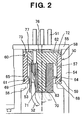
Fig. 2] Fig. 2 is an enlarged vertical sectional view of a terminal connection section of the hybrid compressor depicted inFig. 1 . - [
Fig. 3] Fig. 3 is a process diagram for forming a terminal connection section of the hybrid compressor depicted inFig. 1 . - [
Fig. 4] Fig. 4 is a vertical sectional view of a conventional terminal connection section injected and molded with resin. -
- 1: hybrid compressor
- 2: first compression mechanism
- 3: second compression mechanism
- 10, 30: fixed scroll
- 11, 31: movable scroll
- 12, 32: operational space
- 13, 33: drive shaft
- 14: pulley
- 15: electromagnetic clutch
- 16, 34: ball coupling
- 17: casing
- 18: suction port
- 19: suction path
- 20, 40: suction chamber
- 21, 41: discharge hole
- 22, 42: discharge path
- 23: discharge port
- 35: electric motor
- 36: rotor
- 37: stator
- 38: stator housing
- 39: communication path
- 43: fixed scroll member
- 50: terminal section
- 51: external terminal for power supply
- 52: wire
- 53: connection section
- 54: projected hollow portion
- 55: hermetic seal
- 56: engaging portion
- 57: housing side coupler
- 58, 59: groove
- 60, 61: 0-ring
- 62: power supply-external terminal side coupler
- 63: stator side coupler
- 64, 65: claw
- 66, 67: groove
- 68, 69: engaging portion
- 70: supporting portion
- 71: hollow portion
- 72, 73: claw
- 74, 75: engaging portion
- 76: wave washer
- 77: flat washer
- Hereinafter, a desirable embodiment of the electric compressor according to the present invention will be explained referring to figures.
Fig. 1 depicts an electric compressor according to an embodiment of the present invention, in particular, shows a case where the present invention is applied to a hybrid compressor.Fig. 2 depicts a structure of a terminal connection section of a built-in electric motor in the hybrid compressor depicted inFig. 1 , however, this structure shown inFig. 2 can be applied not only to a hybrid compressor, but also to an electric compressor having only a built-in electric motor as a drive source. - First, the hybrid compressor depicted in
Fig. 1 will be explained. Hybrid compressor 1 is formed as a scroll type compressor, and has afirst compression mechanism 2 and asecond compression mechanism 3.First compression mechanism 2 has a fixedscroll 10, amovable scroll 11 forming a plurality of pairs of operational spaces (fluid pockets) 12 by engaging with fixedscroll 10, adrive shaft 13 drivingmovable scroll 11 at an orbital movement by engaging withmovable scroll 11, anelectromagnetic clutch 15 for an on-off operation of the transmission of a driving force between apulley 14, to which the driving force from a prime mover for running a vehicle (not shown) provided as a first drive source is transmitted, and thedrive shaft 13, aball coupling 16 for preventing the rotation ofmovable scroll 11, and asuction port 18 formed on acasing 17. The fluid to be compressed (for example, refrigerant gas) sucked fromsuction port 18 into asuction chamber 20 through asuction path 19 is taken into operational spaces 12, the operational spaces 12 are moved toward the center of fixedscroll 10 while the volumes of the operational spaces 12 are decreased, and by this operation, the refrigerant gas in the operational spaces 12 is compressed. Adischarge hole 21 is formed on the central portion of fixedscroll 10, and the compressed refrigerant gas is discharged to a high-pressure side of an external refrigerant circuit through thedischarge hole 21, adischarge path 22 and adischarge port 23. - On the other hand,
second compression mechanism 3 has a fixedscroll 30, amovable scroll 31 forming a plurality of pairs of operational spaces (fluid pockets) 32 by engaging with fixedscroll 30, adrive shaft 33 drivingmovable scroll 31 at an orbital movement by engaging withmovable scroll 31, and aball coupling 34 for preventing the rotation ofmovable scroll 31. Anelectric motor 35 is incorporated in order to drive thedrive shaft 33 of thissecond compression mechanism 3.Electric motor 35 has arotor 36 fixed to driveshaft 33 and astator 37, thestator 37 is fixed to astator housing 38 or astator housing 38 which is formed as a part of the compressor housing, and the whole ofelectric motor 35 is contained in thestator housing 38. In thissecond compression mechanism 3, the fluid to be compressed (for example, refrigerant gas) sucked fromsuction port 18 intosuction chamber 20 offirst compression mechanism 2 is sucked into asuction chamber 40 ofsecond compression mechanism 3 through acommunication path 39, the gas is taken intooperational spaces 32, theoperational spaces 32 are moved toward the center of fixedscroll 30 while the volumes of theoperational spaces 32 are decreased, and by this operation, the refrigerant gas in theoperational spaces 32 is compressed. Adischarge hole 41 is formed on the central portion of fixedscroll 30, and the compressed refrigerant gas is discharged to the high-pressure side of the external refrigerant circuit through thedischarge hole 41 and a discharge path 42. - In this embodiment, fixed
scroll 10 offirst compression mechanism 2 and fixedscroll 30 ofsecond compression mechanism 3 are disposed back to back, and both fixedscrolls scroll member 43. - When only
first compression mechanism 2 of hybrid compressor 1 is operated, an electric power is not supplied toelectric motor 35 for drivingsecond compression mechanism 3, and theelectric motor 35 is not rotated. Therefore,second compression mechanism 3 does not operate. When the hybrid compressor 1 is driven only byelectric motor 35, theelectric motor 35 is turned to be on and rotated, the rotation of theelectric motor 35 is transmitted to driveshaft 33 ofsecond compression mechanism 3, and the orbital movement ofmovable scroll 31 is performed by thedrive shaft 33. At that time,electromagnetic clutch 15 offirst compression mechanism 2 is not excited, and the rotation of the prime mover for running a vehicle as a first drive source is not transmitted to thefirst compression mechanism 2. Therefore,first compression mechanism 2 does not operate. When both first andsecond compression mechanisms movable scroll 11 offirst compression mechanism 2 as well aselectric motor 35 is turned to be on and the driving force thereof is transmitted tomovable scroll 31 ofsecond compression mechanism 3. - In hybrid compressor 1 thus constructed,
terminal section 50 ofelectric motor 35 is disposed at an upper portion of the hybrid compressor 1 which is in a mounted condition. In the detailed structure of thisterminal section 50 is formed, as depicted inFigs. 2 and3 .Terminal section 50 has aconnection section 53 between an external terminal forpower supply 51 forelectric motor 35 and the end of awire 52 fromstator 37 ofelectric motor 35.Connection section 53 is disposed in a projectedhollow portion 54 which is formed onstator housing 38 and extends outward, and external terminal forpower supply 51 is attached to ahermetic seal 55 which substantially can close this projectedhollow portion 54. - In this embodiment, an engaging
portion 56 is provided on the inner wall of projectedhollow portion 54, and a cylindricalhousing side coupler 57 is engaged with the engagingportion 56.Grooves housing side coupler 57, and O-rings grooves terminal side coupler 62 is engaged withhousing side coupler 57. Astator side coupler 63, which holdswire 52 fromstator 37 and which is engaged withhousing side coupler 57, is fitted to power supply-externalterminal side coupler 62. The above-describedrespective couplers respective couplers - In this embodiment, the above-described connection section can be formed as follows. First,
housing side coupler 57 is inserted into projectedhollow portion 54. At that time, O-rings grooves housing side coupler 57. One end portion ofhousing side coupler 57 inserted into projectedhollow portion 54 is engaged with engagingportion 56 provided on the inner wall of projectedhollow portion 54, and located at a predetermined position. Further, the positional alignment betweenclaws stator side coupler 63 andgrooves housing side coupler 57 is carried out, and at this state,stator side coupler 63 is inserted from one end side (from lower side inFig. 2 ) of housing side coupler 57 (Fig. 3(A) ). Next,stator side coupler 63 is rotated by 90 degrees in the arrow direction (Fig. 3(B) ). By this,claws stator side coupler 63 are fitted to and engaged withengaging portions housing side coupler 57. Then, a supportingportion 70 of power supply-externalterminal side coupler 62 is inserted into ahollow portion 71 ofstator side coupler 63 from the upper side of projected hollow portion 54 (the upper side inFig. 2 ), andclaws terminal side coupler 62 are engaged withengaging portions Fig. 3(C) ). Furthermore, awave washer 76 is mounted on the upper portion of power supply-externalterminal side coupler 62, and projectedhollow portion 54 is sealed byhermetic seal 55. - In this embodiment, as described above, since
housing side coupler 57 is engaged with projected hollow portion 54 (compressor housing) andfurther connection section 53 can be easily formed only by engaging the respective couplers with each other, as compared with the aforementioned case having an epoxy resin injecting and molding process, the resin injection and molding process can be omitted, the preparation and the curing time for the resin become unnecessary, and the productivity can be improved. Further, in this embodiment, because the couplers are formed from resins so that they can be elastically deformed, respectively, the workability for assembly can be improved. - Further, in this embodiment, as the vibration resistant means for
connection section 53, the following various mechanisms are employed. First, O-rings housing side coupler 57 and projectedhollow portion 54. These O-rings - Further,
wave washer 76 is provided as an elastic member capable of pressinghousing side coupler 57 toward the inside of the compressor housing, in this embodiment, toward the inside of projectedhollow portion 54 ofstator housing 38. This elastic member may be a member other thanwave washer 76, which exhibits a pressing force, for example, another spring member.Housing side coupler 57 is abutted to engagingportion 56 formed in projectedhollow portion 54, and held by the pressing force ofwave washer 76 againsthermetic seal 55. By providing thiswave washer 76, it becomes possible to exhibit a vibration resistant function in the vertical direction ofhousing side coupler 57. It is preferred that aflat washer 77 is interposed between thiswave washer 76 andhousing side coupler 57, in order to prevent the surface ofhousing side coupler 57 from being deformed by the pressing force ofwave washer 76. - Thus, by providing at least one of the above-described respective vibration resistant means, the vibration resistance for the motor terminal connection section can be improved, and occurrence of breakage or momentary electrical interruption of the terminal connection section can be prevented or suppressed.
- The present invention can be applied to any electric compressor incorporating an electric motor for driving a compression mechanism, in particular, can be applied also to an electric compressor of a hybrid compressor in which the respective compression mechanisms are driven by a built-in electric motor and another drive source different therefrom.
Claims (12)
- An electric compressor having a built-in electric motor for driving said compressor and in which a connection section between an external terminal for power supply to said electric motor and the end of a wire from a stator of said electric motor is stored in a compressor housing, characterized in that said connection section is formed from a housing side coupler engaged with said compressor housing, a power supply-external terminal side coupler engaged with said housing side coupler, and a stator side coupler for holding the end of said wire from said stator, fitted to said power supply-external terminal side coupler, and engaged with said housing side coupler.
- The electric compressor according to claim 1, wherein at least one of said housing side coupler, said power supply-external terminal side coupler and said stator side coupler is formed capable of being elastically deformed.
- The electric compressor according to claim 1, wherein a vibration resistant means for mechanically preventing at least one of wire breakage, momentary electrical interruption and breakage of an insulation member ascribed to vibration is provided at a position of said connection section and/or around said connection section.
- The electric compressor according to claim 3, wherein said vibration resistant means has an O-ring interposed between said housing side coupler and said housing.
- The electric compressor according to claim 3, wherein said vibration resistant means has an elastic member capable of pressing said power supply-external terminal side coupler toward the inside of said compressor.
- The electric compressor according to claim 5, wherein said elastic member is a wave washer.
- The electric compressor according to claim 5, wherein said connection section is formed in a projected hollow portion which is formed on said compressor housing in that said electric motor is stored and said stator is fixed and which extends outward.
- The electric compressor according to claim 7, wherein said projected hollow portion is substantially closed against outside of said compressor.
- The electric compressor according to claim 1, wherein said electric compressor is a hybrid compressor in which a first compression mechanism driven only by a first drive source different from said built-in electric motor and a second compression mechanism driven only by said electric motor provided as a second drive source are provided in parallel and into which both compression mechanisms are incorporated integrally.
- The electric compressor according to claim 9, wherein said first and second compression mechanisms are scroll-type compression mechanisms, and the fixed scrolls of said both compression mechanisms are disposed back to back.
- The electric compressor according to claim 10, wherein said fixed scrolls disposed back to back are formed from an integral fixed scroll member.
- The electric compressor according to claim 9, wherein said first drive source is a prime mover for a vehicle.
Applications Claiming Priority (2)
| Application Number | Priority Date | Filing Date | Title |
|---|---|---|---|
| JP2005377875A JP4549968B2 (en) | 2005-12-28 | 2005-12-28 | Electric compressor |
| PCT/JP2006/326008 WO2007074852A1 (en) | 2005-12-28 | 2006-12-27 | Electric compressor |
Publications (2)
| Publication Number | Publication Date |
|---|---|
| EP1967732A1 true EP1967732A1 (en) | 2008-09-10 |
| EP1967732A4 EP1967732A4 (en) | 2017-01-25 |
Family
ID=38218073
Family Applications (1)
| Application Number | Title | Priority Date | Filing Date |
|---|---|---|---|
| EP06843390.3A Withdrawn EP1967732A4 (en) | 2005-12-28 | 2006-12-27 | Electric compressor |
Country Status (5)
| Country | Link |
|---|---|
| US (1) | US8231365B2 (en) |
| EP (1) | EP1967732A4 (en) |
| JP (1) | JP4549968B2 (en) |
| CN (1) | CN101346547B (en) |
| WO (1) | WO2007074852A1 (en) |
Cited By (3)
| Publication number | Priority date | Publication date | Assignee | Title |
|---|---|---|---|---|
| FR2973604A1 (en) * | 2011-03-31 | 2012-10-05 | Valeo Thermal Sys Japan Co | Device for fixing rectilinear metallic rigid rod on wall of casing of electric compressor in air-conditioning unit of e.g. hybrid car, has flexible projection defining housing to receive lock that exerts force on projection |
| US10485128B2 (en) | 2012-07-27 | 2019-11-19 | Emerson Climate Technologies, Inc. | Compressor protection module |
| EP3736407A1 (en) * | 2019-05-09 | 2020-11-11 | LG Electronics Inc. | Electric compressor |
Families Citing this family (6)
| Publication number | Priority date | Publication date | Assignee | Title |
|---|---|---|---|---|
| US8939734B2 (en) * | 2007-08-28 | 2015-01-27 | Emerson Climate Technologies, Inc. | Molded plug for a compressor |
| JP5308650B2 (en) * | 2007-10-23 | 2013-10-09 | サンデン株式会社 | Electric compressor terminal device |
| JP5109642B2 (en) * | 2007-12-18 | 2012-12-26 | 株式会社豊田自動織機 | Electric compressor |
| US8939735B2 (en) * | 2009-03-27 | 2015-01-27 | Emerson Climate Technologies, Inc. | Compressor plug assembly |
| JP2015208164A (en) * | 2014-04-22 | 2015-11-19 | サンデンホールディングス株式会社 | electric compressor |
| DE102015114192A1 (en) * | 2015-08-26 | 2017-03-02 | Ebm-Papst Mulfingen Gmbh & Co. Kg | Connection system for plug positioning |
Family Cites Families (17)
| Publication number | Priority date | Publication date | Assignee | Title |
|---|---|---|---|---|
| US2684401A (en) * | 1951-11-05 | 1954-07-20 | Electro Snap Switch & Mfg Co | Sealtight conduit connector |
| US3457867A (en) * | 1968-01-25 | 1969-07-29 | Red Jacket Mfg Co | Fluid pumping system |
| AT314008B (en) * | 1970-09-25 | 1974-03-11 | Vibro Meter Ag | Cable connector |
| JPS5937862U (en) * | 1982-08-31 | 1984-03-09 | 株式会社東芝 | compressor terminal protection box |
| JPS59110896A (en) * | 1982-12-15 | 1984-06-26 | Ebara Corp | Submersible motor pump |
| US4836794A (en) * | 1988-08-05 | 1989-06-06 | Kern Engineering & Mfg. Corp. | EMI and environmentally protected connector cap |
| JPH08219060A (en) * | 1995-02-17 | 1996-08-27 | Mitsubishi Heavy Ind Ltd | Hermetic compressor |
| JP2002155862A (en) * | 2000-11-22 | 2002-05-31 | Toyota Industries Corp | Compressor |
| JP2002276550A (en) * | 2001-03-14 | 2002-09-25 | Matsushita Electric Ind Co Ltd | Method for connecting compressor with built-in motor to external wiring, connectors used for the same, compressor with built-in motor using them |
| JP4044341B2 (en) * | 2001-09-14 | 2008-02-06 | サンデン株式会社 | Hybrid compressor |
| AU2003200332B2 (en) * | 2002-02-08 | 2005-11-17 | Sanden Corporation | Hybrid compressor |
| JP3823920B2 (en) * | 2002-12-27 | 2006-09-20 | 三菱電機株式会社 | Electro-hydraulic power steering device |
| JP2004270614A (en) * | 2003-03-11 | 2004-09-30 | Sanden Corp | Electric compressor |
| JP4063253B2 (en) * | 2003-06-11 | 2008-03-19 | 株式会社デンソー | Hermetic electric compressor |
| US7197892B2 (en) * | 2003-06-11 | 2007-04-03 | Denso Corporation | Encapsulated electrically driven compressor |
| JP4046018B2 (en) * | 2003-06-12 | 2008-02-13 | 住友電装株式会社 | connector |
| JP2005207328A (en) * | 2004-01-23 | 2005-08-04 | Toyota Industries Corp | Compressor |
-
2005
- 2005-12-28 JP JP2005377875A patent/JP4549968B2/en not_active Expired - Fee Related
-
2006
- 2006-12-27 US US12/159,775 patent/US8231365B2/en not_active Expired - Fee Related
- 2006-12-27 EP EP06843390.3A patent/EP1967732A4/en not_active Withdrawn
- 2006-12-27 CN CN2006800487779A patent/CN101346547B/en not_active Expired - Fee Related
- 2006-12-27 WO PCT/JP2006/326008 patent/WO2007074852A1/en not_active Ceased
Non-Patent Citations (1)
| Title |
|---|
| See references of WO2007074852A1 * |
Cited By (3)
| Publication number | Priority date | Publication date | Assignee | Title |
|---|---|---|---|---|
| FR2973604A1 (en) * | 2011-03-31 | 2012-10-05 | Valeo Thermal Sys Japan Co | Device for fixing rectilinear metallic rigid rod on wall of casing of electric compressor in air-conditioning unit of e.g. hybrid car, has flexible projection defining housing to receive lock that exerts force on projection |
| US10485128B2 (en) | 2012-07-27 | 2019-11-19 | Emerson Climate Technologies, Inc. | Compressor protection module |
| EP3736407A1 (en) * | 2019-05-09 | 2020-11-11 | LG Electronics Inc. | Electric compressor |
Also Published As
| Publication number | Publication date |
|---|---|
| US8231365B2 (en) | 2012-07-31 |
| EP1967732A4 (en) | 2017-01-25 |
| JP4549968B2 (en) | 2010-09-22 |
| US20090269221A1 (en) | 2009-10-29 |
| CN101346547B (en) | 2012-06-27 |
| JP2007177718A (en) | 2007-07-12 |
| WO2007074852A1 (en) | 2007-07-05 |
| CN101346547A (en) | 2009-01-14 |
Similar Documents
| Publication | Publication Date | Title |
|---|---|---|
| US7982348B2 (en) | Electric wire holding structure for electric compressor and electric wire holding method for electric compressor | |
| US9394905B2 (en) | Motor-driven compressor including a shield to block electromagnetic noise | |
| US20190052144A1 (en) | Compressor | |
| US7806712B2 (en) | Electric compressor | |
| WO2014091821A1 (en) | Electric compressor and method for assembling same | |
| CA2610060C (en) | Electric compressor | |
| US10107293B2 (en) | Electric compressor | |
| US8231365B2 (en) | Electric compressor | |
| EP4365449B1 (en) | Electric compressor | |
| EP1867874B1 (en) | Electric motor-driven compressor | |
| US7344400B2 (en) | Terminal connection structure of motor incorporated within a compressor | |
| EP2230404A1 (en) | Terminal device for electric compressor | |
| EP2221477A1 (en) | Electric compressor terminal device | |
| US20100247353A1 (en) | Terminal device for electric compressor | |
| JP5053523B2 (en) | Electric compressor | |
| US20100247346A1 (en) | Terminal device for electric compressor | |
| JP2007315222A (en) | Electric compressor |
Legal Events
| Date | Code | Title | Description |
|---|---|---|---|
| PUAI | Public reference made under article 153(3) epc to a published international application that has entered the european phase |
Free format text: ORIGINAL CODE: 0009012 |
|
| 17P | Request for examination filed |
Effective date: 20080623 |
|
| AK | Designated contracting states |
Kind code of ref document: A1 Designated state(s): DE FR |
|
| DAX | Request for extension of the european patent (deleted) | ||
| RBV | Designated contracting states (corrected) |
Designated state(s): DE FR |
|
| RAP1 | Party data changed (applicant data changed or rights of an application transferred) |
Owner name: SANDEN HOLDINGS CORPORATION |
|
| RA4 | Supplementary search report drawn up and despatched (corrected) |
Effective date: 20161222 |
|
| RIC1 | Information provided on ipc code assigned before grant |
Ipc: F04C 29/00 20060101ALI20161216BHEP Ipc: F25B 31/02 20060101ALI20161216BHEP Ipc: F25B 1/04 20060101ALI20161216BHEP Ipc: F04B 39/00 20060101AFI20161216BHEP Ipc: H02K 5/22 20060101ALI20161216BHEP Ipc: H01R 33/97 20060101ALI20161216BHEP Ipc: F04C 18/02 20060101ALI20161216BHEP Ipc: H02K 7/14 20060101ALI20161216BHEP Ipc: F04C 23/00 20060101ALI20161216BHEP |
|
| STAA | Information on the status of an ep patent application or granted ep patent |
Free format text: STATUS: THE APPLICATION HAS BEEN WITHDRAWN |
|
| 18W | Application withdrawn |
Effective date: 20170217 |