EP1967711A1 - Exhaust emission control device - Google Patents
Exhaust emission control device Download PDFInfo
- Publication number
- EP1967711A1 EP1967711A1 EP06843258A EP06843258A EP1967711A1 EP 1967711 A1 EP1967711 A1 EP 1967711A1 EP 06843258 A EP06843258 A EP 06843258A EP 06843258 A EP06843258 A EP 06843258A EP 1967711 A1 EP1967711 A1 EP 1967711A1
- Authority
- EP
- European Patent Office
- Prior art keywords
- oxidation catalyst
- catalyst
- heater
- reformer
- control device
- Prior art date
- Legal status (The legal status is an assumption and is not a legal conclusion. Google has not performed a legal analysis and makes no representation as to the accuracy of the status listed.)
- Withdrawn
Links
Images


Classifications
-
- F—MECHANICAL ENGINEERING; LIGHTING; HEATING; WEAPONS; BLASTING
- F01—MACHINES OR ENGINES IN GENERAL; ENGINE PLANTS IN GENERAL; STEAM ENGINES
- F01N—GAS-FLOW SILENCERS OR EXHAUST APPARATUS FOR MACHINES OR ENGINES IN GENERAL; GAS-FLOW SILENCERS OR EXHAUST APPARATUS FOR INTERNAL-COMBUSTION ENGINES
- F01N3/00—Exhaust or silencing apparatus having means for purifying, rendering innocuous, or otherwise treating exhaust
- F01N3/08—Exhaust or silencing apparatus having means for purifying, rendering innocuous, or otherwise treating exhaust for rendering innocuous
- F01N3/0807—Exhaust or silencing apparatus having means for purifying, rendering innocuous, or otherwise treating exhaust for rendering innocuous by using absorbents or adsorbents
-
- B—PERFORMING OPERATIONS; TRANSPORTING
- B01—PHYSICAL OR CHEMICAL PROCESSES OR APPARATUS IN GENERAL
- B01D—SEPARATION
- B01D53/00—Separation of gases or vapours; Recovering vapours of volatile solvents from gases; Chemical or biological purification of waste gases, e.g. engine exhaust gases, smoke, fumes, flue gases, aerosols
- B01D53/34—Chemical or biological purification of waste gases
- B01D53/92—Chemical or biological purification of waste gases of engine exhaust gases
- B01D53/94—Chemical or biological purification of waste gases of engine exhaust gases by catalytic processes
- B01D53/9404—Removing only nitrogen compounds
- B01D53/9409—Nitrogen oxides
- B01D53/9431—Processes characterised by a specific device
-
- F—MECHANICAL ENGINEERING; LIGHTING; HEATING; WEAPONS; BLASTING
- F01—MACHINES OR ENGINES IN GENERAL; ENGINE PLANTS IN GENERAL; STEAM ENGINES
- F01N—GAS-FLOW SILENCERS OR EXHAUST APPARATUS FOR MACHINES OR ENGINES IN GENERAL; GAS-FLOW SILENCERS OR EXHAUST APPARATUS FOR INTERNAL-COMBUSTION ENGINES
- F01N13/00—Exhaust or silencing apparatus characterised by constructional features
- F01N13/009—Exhaust or silencing apparatus characterised by constructional features having two or more separate purifying devices arranged in series
-
- F—MECHANICAL ENGINEERING; LIGHTING; HEATING; WEAPONS; BLASTING
- F01—MACHINES OR ENGINES IN GENERAL; ENGINE PLANTS IN GENERAL; STEAM ENGINES
- F01N—GAS-FLOW SILENCERS OR EXHAUST APPARATUS FOR MACHINES OR ENGINES IN GENERAL; GAS-FLOW SILENCERS OR EXHAUST APPARATUS FOR INTERNAL-COMBUSTION ENGINES
- F01N13/00—Exhaust or silencing apparatus characterised by constructional features
- F01N13/009—Exhaust or silencing apparatus characterised by constructional features having two or more separate purifying devices arranged in series
- F01N13/0097—Exhaust or silencing apparatus characterised by constructional features having two or more separate purifying devices arranged in series the purifying devices are arranged in a single housing
-
- F—MECHANICAL ENGINEERING; LIGHTING; HEATING; WEAPONS; BLASTING
- F01—MACHINES OR ENGINES IN GENERAL; ENGINE PLANTS IN GENERAL; STEAM ENGINES
- F01N—GAS-FLOW SILENCERS OR EXHAUST APPARATUS FOR MACHINES OR ENGINES IN GENERAL; GAS-FLOW SILENCERS OR EXHAUST APPARATUS FOR INTERNAL-COMBUSTION ENGINES
- F01N3/00—Exhaust or silencing apparatus having means for purifying, rendering innocuous, or otherwise treating exhaust
- F01N3/08—Exhaust or silencing apparatus having means for purifying, rendering innocuous, or otherwise treating exhaust for rendering innocuous
- F01N3/0807—Exhaust or silencing apparatus having means for purifying, rendering innocuous, or otherwise treating exhaust for rendering innocuous by using absorbents or adsorbents
- F01N3/0814—Exhaust or silencing apparatus having means for purifying, rendering innocuous, or otherwise treating exhaust for rendering innocuous by using absorbents or adsorbents combined with catalytic converters, e.g. NOx absorption/storage reduction catalysts
-
- F—MECHANICAL ENGINEERING; LIGHTING; HEATING; WEAPONS; BLASTING
- F01—MACHINES OR ENGINES IN GENERAL; ENGINE PLANTS IN GENERAL; STEAM ENGINES
- F01N—GAS-FLOW SILENCERS OR EXHAUST APPARATUS FOR MACHINES OR ENGINES IN GENERAL; GAS-FLOW SILENCERS OR EXHAUST APPARATUS FOR INTERNAL-COMBUSTION ENGINES
- F01N3/00—Exhaust or silencing apparatus having means for purifying, rendering innocuous, or otherwise treating exhaust
- F01N3/08—Exhaust or silencing apparatus having means for purifying, rendering innocuous, or otherwise treating exhaust for rendering innocuous
- F01N3/10—Exhaust or silencing apparatus having means for purifying, rendering innocuous, or otherwise treating exhaust for rendering innocuous by thermal or catalytic conversion of noxious components of exhaust
- F01N3/24—Exhaust or silencing apparatus having means for purifying, rendering innocuous, or otherwise treating exhaust for rendering innocuous by thermal or catalytic conversion of noxious components of exhaust characterised by constructional aspects of converting apparatus
- F01N3/28—Construction of catalytic reactors
-
- F—MECHANICAL ENGINEERING; LIGHTING; HEATING; WEAPONS; BLASTING
- F01—MACHINES OR ENGINES IN GENERAL; ENGINE PLANTS IN GENERAL; STEAM ENGINES
- F01N—GAS-FLOW SILENCERS OR EXHAUST APPARATUS FOR MACHINES OR ENGINES IN GENERAL; GAS-FLOW SILENCERS OR EXHAUST APPARATUS FOR INTERNAL-COMBUSTION ENGINES
- F01N3/00—Exhaust or silencing apparatus having means for purifying, rendering innocuous, or otherwise treating exhaust
- F01N3/08—Exhaust or silencing apparatus having means for purifying, rendering innocuous, or otherwise treating exhaust for rendering innocuous
- F01N3/10—Exhaust or silencing apparatus having means for purifying, rendering innocuous, or otherwise treating exhaust for rendering innocuous by thermal or catalytic conversion of noxious components of exhaust
- F01N3/24—Exhaust or silencing apparatus having means for purifying, rendering innocuous, or otherwise treating exhaust for rendering innocuous by thermal or catalytic conversion of noxious components of exhaust characterised by constructional aspects of converting apparatus
- F01N3/28—Construction of catalytic reactors
- F01N3/2803—Construction of catalytic reactors characterised by structure, by material or by manufacturing of catalyst support
- F01N3/2807—Metal other than sintered metal
- F01N3/281—Metallic honeycomb monoliths made of stacked or rolled sheets, foils or plates
-
- B—PERFORMING OPERATIONS; TRANSPORTING
- B01—PHYSICAL OR CHEMICAL PROCESSES OR APPARATUS IN GENERAL
- B01D—SEPARATION
- B01D2255/00—Catalysts
- B01D2255/90—Physical characteristics of catalysts
- B01D2255/91—NOx-storage component incorporated in the catalyst
-
- F—MECHANICAL ENGINEERING; LIGHTING; HEATING; WEAPONS; BLASTING
- F01—MACHINES OR ENGINES IN GENERAL; ENGINE PLANTS IN GENERAL; STEAM ENGINES
- F01N—GAS-FLOW SILENCERS OR EXHAUST APPARATUS FOR MACHINES OR ENGINES IN GENERAL; GAS-FLOW SILENCERS OR EXHAUST APPARATUS FOR INTERNAL-COMBUSTION ENGINES
- F01N2240/00—Combination or association of two or more different exhaust treating devices, or of at least one such device with an auxiliary device, not covered by indexing codes F01N2230/00 or F01N2250/00, one of the devices being
- F01N2240/30—Combination or association of two or more different exhaust treating devices, or of at least one such device with an auxiliary device, not covered by indexing codes F01N2230/00 or F01N2250/00, one of the devices being a fuel reformer
-
- F—MECHANICAL ENGINEERING; LIGHTING; HEATING; WEAPONS; BLASTING
- F01—MACHINES OR ENGINES IN GENERAL; ENGINE PLANTS IN GENERAL; STEAM ENGINES
- F01N—GAS-FLOW SILENCERS OR EXHAUST APPARATUS FOR MACHINES OR ENGINES IN GENERAL; GAS-FLOW SILENCERS OR EXHAUST APPARATUS FOR INTERNAL-COMBUSTION ENGINES
- F01N2610/00—Adding substances to exhaust gases
- F01N2610/03—Adding substances to exhaust gases the substance being hydrocarbons, e.g. engine fuel
-
- Y—GENERAL TAGGING OF NEW TECHNOLOGICAL DEVELOPMENTS; GENERAL TAGGING OF CROSS-SECTIONAL TECHNOLOGIES SPANNING OVER SEVERAL SECTIONS OF THE IPC; TECHNICAL SUBJECTS COVERED BY FORMER USPC CROSS-REFERENCE ART COLLECTIONS [XRACs] AND DIGESTS
- Y02—TECHNOLOGIES OR APPLICATIONS FOR MITIGATION OR ADAPTATION AGAINST CLIMATE CHANGE
- Y02T—CLIMATE CHANGE MITIGATION TECHNOLOGIES RELATED TO TRANSPORTATION
- Y02T10/00—Road transport of goods or passengers
- Y02T10/10—Internal combustion engine [ICE] based vehicles
- Y02T10/12—Improving ICE efficiencies
Definitions
- the present invention relates to an exhaust emission control device.
- Exhaust gas from a diesel engine has heretofore been purified by a catalyst incorporated in an exhaust pipe through which the exhaust gas flows.
- a catalyst incorporated in an exhaust pipe through which the exhaust gas flows.
- a NO x -absorption reduction catalyst which has a property of oxidizing NO x in the exhaust gas to temporarily absorb the same in the form of nitrate when an air/fuel ratio of the exhaust gas is lean, and conducting decomposition into NO x for reduction and purification thereof with the assistance of unburned HC and CO when the oxygen concentration in the exhaust gas is lowered.
- NO x -absorption reduction catalyst having the above-mentioned property is, for example, a catalyst made from alumina and carrying platinum and barium or a catalyst made from alumina and carrying platinum and potassium.
- lowering the operational air/fuel ratio in the engine can lower the O 2 concentration and increase the reduction components such as unburned HC and CO in the exhaust gas for facilitation of decomposition and discharge of NO x .
- a NO x -absorption reduction catalyst in an exhaust emission control device for a diesel engine, it is difficult to operate the engine with rich air/fuel ratio.
- NO x in a driving condition that a combustion temperature (about 220-250°C) necessary for reaction of HC with O 2 (combustion) cannot be obtained on the NO x -absorption reduction catalyst (for example, in driving at reduced speed on city roads often congested with traffic), NO x cannot be efficiently decomposed and discharged from the reduction catalyst and the regeneration of the reduction catalyst does not efficiently progress, disadvantageously resulting in decrease of recovery ratio of NO x -absorption sites occupied in volume of the catalyst to deteriorate absorption capacity.
- the invention was made in view of the above and has its object to provide an exhaust emission control device which can effectively regenerate a NO x -absorption reduction catalyst even in a relatively low temperature region to improve NO x reduction ratio while minimizing deterioration of fuel economy,.
- the invention is directed to an exhaust gas emission control device comprising a reformer incorporated in a gas pipe through which exhaust gas from an engine flows, said reformer having a fuel adding device, a heater and a reforming catalyst, and a NO x -absorption reduction catalyst arranged downstream of the reformer.
- NO x can be efficiently decomposed and discharged from the NO x -absorption reduction catalyst, so that regeneration of the NO x -absorption reduction catalyst effectively progresses, resulting in increase of recovery ratio of NO x -absorption sites occupied in volume of the catalyst to prevent deterioration of absorption capacity and of fuel economy, leading to attainment of practical application.
- the heater in the reformer may be constituted by an anterior oxidation catalyst unit with oxidation catalyst having heating function being evenly arranged.
- the anterior oxidation catalyst unit may be a membrane metal heater comprising a strip-like metal membrane coated with oxidation catalyst and capable of temperature raising through application of current so as to serve as oxidation catalyst with heating function and an insulating alumina tape as oxidation catalyst, the metal membrane and the insulating tape being wound together spirally in an overlapping manner.
- the anterior oxidation catalyst unit may be a wire mesh heater comprising wire sheets coated with oxidation catalyst and capable of temperature raising through application of current so as to serve as oxidation catalyst with heating function and insulating alumina meshes as oxidation catalyst, the wire sheet and the insulating mesh being laminated alternately and plurally in a direction of flow of the exhaust gas.
- the heater in the reformer may comprise an anterior oxidation catalyst unit with a centrally arranged oxidation catalyst with heating function, a mixer being arranged between the anterior oxidation catalyst unit and the reforming catalyst.
- An exhaust emission control device has excellent effects that a NO x -absorption reduction catalyst can be effectively regenerated even in a relatively low temperature region to improve NO x reduction ratio while minimizing the deterioration of fuel economy.
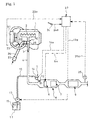
- Fig. 1 shows an embodiment of the invention.
- a reformer 8 having a fuel adding device 5, a heater 6 and a reforming catalyst 7.
- a NO x -absorption reduction catalyst 9 is arranged downstream of the reformer.
- the fuel adding device 5 in the reformer 8 comprises an injection nozzle 10 arranged on the entry side of the heater 6 and connected via a fuel supply pipe 12 to a fuel tank 11.
- Fuel 15 such as light oil may be added as reducing agent to the entry side of the heater 6 via the injection nozzle 10 by driving a supply pump 13, which is incorporated in the fuel supply pipe 12, and opening an addition valve 14.
- the heater 6 in the reformer 8 is constituted by an anterior oxidation catalyst unit with evenly arranged oxidation catalyst with heating function.
- the heater 6 may be, for example, a membrane metal heater 18 as shown in Fig. 2 which comprises a strip-like metal membrane 16 coated with oxidation catalyst and capable of temperature raising through application of current so as to serve as oxidation catalyst with heating function and an insulating alumina tape 17 as oxidation catalyst, the metal membrane and the insulating tape being wound together spirally in an overlapping manner.
- it may be a wire mesh heater 20 as shown in Fig.
- the reforming catalyst 7 in the reformer 8 serves to decompose the HC component, which is produced due to fuel addition by the fuel adding device 5, into H 2 and CO in the exhaust gas 3.
- This kind of reforming catalyst 7 may comprise, for example, an oxide such as alumina or silica or a complex oxide such as zeolite as a carrier carrying for example Pd, Pt or Rh as active metal.
- a controller 22 serving as engine control computer (ECU: Electronic Control Unit)
- current driving conditions are determined by a revolution speed signal 23a from a revolution speed sensor 23 which detects revolution speed of the diesel engine 1, a load signal 24a from an accelerator sensor 24 which detects a step-in angle of an accelerator pedal and a temperature signal 25a from a temperature sensor 25 which detects temperature of the exhaust gas 3 having passed through the reformer 8 and NO x -absorption reduction catalyst 9.
- an amount of fuel 15 to be added by the fuel adding device 5, time of current application to the heater 6 and the like are determined so that the controller 22 outputs a drive command signal 13a to the supply pump 13, an opening/closing command signal 14a to the addition valve 14 and a current application command signal 6a to the heater 6.
- the fuel 15 is injected via the injection nozzle 10 in the fuel adding device 5 and is passed through the heater 6 to produce concentrated HC gas and raise the exhaust gas 3 to a temperature (about 300°C) required for action of the reforming catalyst 7.
- the HC gas is guided together with the exhaust gas 3 to the reforming catalyst 7 and reacts with O 2 coexisting in the ambient atmosphere to raise the ambient temperature and consumes O 2 ; thereafter, the HC gas is decomposed into highly reactive H 2 and CO which are introduced into the posterior NO x -absorption reduction catalyst 9 for regeneration of the same.
- reference numeral 26 denotes a suction pipe for the diesel engine 1 having an air cleaner 27 at its upstream end.
- Incorporated in the suction pipe 26 downstream thereof is a compressor 29 driven by a turbine 28 which in turn is incorporated in the exhaust pipe 4 on a discharge side of the exhaust manifold 2.
- the turbine 28 and the compressor 29 constitutes a turbocharger 30.
- Incorporated in the suction pipe 26 downstream of the compressor 29 is an intercooler 31.
- the fuel 15 is added as reducing agent via the injection nozzle 10 of the fuel adding device 5 to the entry side of the heater 6 such as the membrane metal heater 18 (see Fig. 2 ) or the wire mesh heater 20 (see Fig. 3 ) with oxidation catalyst floor temperature being raised through application of current so that the fuel 15 is heated by the heater 6 to produce concentrated HC gas while the exhaust gas 3 is raised to a temperature (about 300°C) required for the action of the reforming catalyst 7; the HC gas is guided together with the exhaust gas 3 to the reforming catalyst 7 and reacts with O 2 coexisting in the ambient atmosphere.
- the heater 6 such as the membrane metal heater 18 (see Fig. 2 ) or the wire mesh heater 20 (see Fig. 3 ) with oxidation catalyst floor temperature being raised through application of current so that the fuel 15 is heated by the heater 6 to produce concentrated HC gas while the exhaust gas 3 is raised to a temperature (about 300°C) required for the action of the reforming catalyst 7; the HC gas is guided together with the exhaust gas 3 to the
- the HC gas is decomposed into high reactive H 2 and CO which are guide to the posterior NO x -absorption reduction catalyst 9 and on the surface of the reduction catalyst 9 NO x is efficiently reduced into N 2 even at a temperature lower than a conventional combustion temperature in fuel addition.
- the heater 6 are constituted by the anterior oxidation catalyst unit solely with oxidation catalysts having heating function, the whole of the anterior oxidation catalyst unit must be raised to a temperature required for action thereof, which would require greater electricity.
- the heater 6 is constituted by an anterior oxidation catalyst unit with the evenly arranged oxidation catalyst or catalysts with heating function such as the membrane metal heater 18 (see Fig. 2 ) or the wire mesh heater 20 (see Fig.
- the membrane metal heater 18 may be formed by spirally winding the single strip-like metal membrane 16 and plural insulating alumina tapes 17 in an overlapping manner; or the wire mesh heater 20 may be formed by laminating the single wire sheet 19 and the plural insulating alumina meshes 19' alternately and plurally.
- the reason why the reforming catalyst 7 is made to have no heating function is that if the reforming catalyst 7 were of heating function, then the temperature on the entry side of the reforming catalyst 7 might not be sufficiently raised and would bring abut wasteful portions as catalyst.
- the anterior oxidation catalyst unit is arranged upstream of the reforming catalyst 7, so that the whole including the entry side of the reforming catalyst 7 can be increased in temperature and bring about no wasteful portions.
- Fig. 4 shows a further embodiment of the invention in which parts similar to those in Fig. 1 are represented by the same reference numerals.
- a heater 6 in a reformer 8 is constituted by an anterior oxidation catalyst unit 33 having centrally arranged oxidation catalyst 32 with heating function, a mixer 34 being arranged between the anterior oxidation catalyst unit 33 and a reforming catalyst 7.
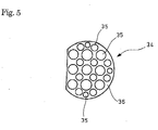
- the mixer 34 is constituted, for example, by a plurality of disks 36 arranged in a direction of flow of the exhaust gas 3, each disk being partly cut out and having a number of through holes 35 with different diameters as shown in Fig. 5 .
- the exhaust gas 3 is raised to a temperature (about 300°C) required for action of the reforming catalyst 7 and the HC gas is guided together with the exhaust gas 3 to the reforming catalyst 7 and reacts with O 2 coexisting with the ambient atmosphere.
- the HC gas is decomposed into highly reactive H 2 and CO which are guided to a posterior NO x absorption reduction catalyst 9 and, on the surface of the NO x -absorption reduction catalyst 9, NO x is effectively reduced into N 2 even at a temperature lower than a conventional combustion temperature in fuel addition.
- the heater 6 is constituted by the anterior oxidation catalyst unit 33 with the centrally arranged oxidation catalyst 32 with heating function, so that by centralizing the electricity to the centrally arranged oxidation catalyst 32 with heating function, the temperature enough for starting the oxidization of the fuel 15 can be maintained on the oxidation catalyst 32 with heating function by electricity less than that of the Fig. 1 embodiment, so that the NO x -absorption reduction catalyst 9 can be efficiently regenerated through a minimum level of current application to the heater 6.
- the NO x -absorption reduction catalyst can be efficiently regenerated even in a relatively low temperature region to improve the NO x reduction ratio while minimizing the deterioration of fuel economy.
Landscapes
- Engineering & Computer Science (AREA)
- Chemical & Material Sciences (AREA)
- Chemical Kinetics & Catalysis (AREA)
- Combustion & Propulsion (AREA)
- General Engineering & Computer Science (AREA)
- Mechanical Engineering (AREA)
- Health & Medical Sciences (AREA)
- Toxicology (AREA)
- Biomedical Technology (AREA)
- Environmental & Geological Engineering (AREA)
- Analytical Chemistry (AREA)
- General Chemical & Material Sciences (AREA)
- Oil, Petroleum & Natural Gas (AREA)
- Exhaust Gas After Treatment (AREA)
- Exhaust Gas Treatment By Means Of Catalyst (AREA)
Abstract
Description
- The present invention relates to an exhaust emission control device.
- Exhaust gas from a diesel engine has heretofore been purified by a catalyst incorporated in an exhaust pipe through which the exhaust gas flows. Known as this kind of catalyst is a NOx-absorption reduction catalyst which has a property of oxidizing NOx in the exhaust gas to temporarily absorb the same in the form of nitrate when an air/fuel ratio of the exhaust gas is lean, and conducting decomposition into NOx for reduction and purification thereof with the assistance of unburned HC and CO when the oxygen concentration in the exhaust gas is lowered.
- Known as this kind of NOx-absorption reduction catalyst having the above-mentioned property is, for example, a catalyst made from alumina and carrying platinum and barium or a catalyst made from alumina and carrying platinum and potassium.
- Since no further NOx can be absorbed once an absorbed NOx amount increases into saturation in the NOx-absorption reduction catalyst, it is periodically required to lower the O2 concentration in the exhaust gas flowing to the NOx-absorption reduction catalyst to decompose and discharge NOx.
- For example, in application to a gasoline engine, lowering the operational air/fuel ratio in the engine (operating the engine with rich air/fuel ratio) can lower the O2 concentration and increase the reduction components such as unburned HC and CO in the exhaust gas for facilitation of decomposition and discharge of NOx. However, in use of a NOx-absorption reduction catalyst in an exhaust emission control device for a diesel engine, it is difficult to operate the engine with rich air/fuel ratio.
- Thus, it has been necessary that fuel (HC) is added to the exhaust gas upstream of a NOx-absorption reduction catalyst, the added fuel being reacted as reducing agent with O2 on the reduction catalyst so as to lower the O2 concentration in the exhaust gas (see, for example, Reference 1).
- [Reference 1]
JP 2000-356127A - However, in such fuel addition upstream of a NOx-absorption reduction catalyst, part of HC produced due to evaporation of the added fuel reacts with O2 (combustion) in the exhaust gas on the NOx-absorption reduction catalyst, and decomposition and discharge of NOx are started after the O2 concentration becomes substantially zero in an ambient atmosphere around the NOx-absorption reduction catalyst. Thus, in a driving condition that a combustion temperature (about 220-250°C) necessary for reaction of HC with O2 (combustion) cannot be obtained on the NOx-absorption reduction catalyst (for example, in driving at reduced speed on city roads often congested with traffic), NOx cannot be efficiently decomposed and discharged from the reduction catalyst and the regeneration of the reduction catalyst does not efficiently progress, disadvantageously resulting in decrease of recovery ratio of NOx-absorption sites occupied in volume of the catalyst to deteriorate absorption capacity.
- Temperature raise control to the engine and/or increase in amount of fuel to be added so as to overcome the problem will, however, bring about substantial deterioration of fuel economy, resulting in difficulty in practical application.
- The invention was made in view of the above and has its object to provide an exhaust emission control device which can effectively regenerate a NOx-absorption reduction catalyst even in a relatively low temperature region to improve NOx reduction ratio while minimizing deterioration of fuel economy,.
- The invention is directed to an exhaust gas emission control device comprising a reformer incorporated in a gas pipe through which exhaust gas from an engine flows, said reformer having a fuel adding device, a heater and a reforming catalyst, and a NOx-absorption reduction catalyst arranged downstream of the reformer.
- The above-mentioned means can obtain the following workings or operations.
- With the exhaust gas from the engine being delivered via the exhaust pipe to the reformer, fuel is added as reducing agent by the fuel adding device on an entry side of the heater. Thus, the fuel is heated by the heater to produce concentrated HC gas with the exhaust gas being raised to a temperature required for action of the reforming catalyst. The HC gas is guided together with the exhaust gas to the reforming catalyst. After it reacts with O2 coexisting in the ambient atmosphere to raise the ambient temperature and O2 is consumed, the HC gas is decomposed into highly reactive H2 and CO which are guided to a posterior NOx-absorption reduction catalyst and, on a surface of the NOx-absorption reduction catalyst, NOx is effectively reduced into N2 even at a temperature lower than a conventional combustion temperature in fuel addition.
- As a result, even in a driving condition that a reaction temperature necessary for reaction of HC with O2 (combustion) cannot be obtained on the NOx-absorption reduction catalyst (for example, in driving at reduced speed on city roads often congested with traffic), by operating the reformer with a minimum level of electricity and without temperature raise control to the engine nor increase in amount of fuel to be added, NOx can be efficiently decomposed and discharged from the NOx-absorption reduction catalyst, so that regeneration of the NOx-absorption reduction catalyst effectively progresses, resulting in increase of recovery ratio of NOx-absorption sites occupied in volume of the catalyst to prevent deterioration of absorption capacity and of fuel economy, leading to attainment of practical application.
- In the exhaust emission control device, the heater in the reformer may be constituted by an anterior oxidation catalyst unit with oxidation catalyst having heating function being evenly arranged.
- The anterior oxidation catalyst unit may be a membrane metal heater comprising a strip-like metal membrane coated with oxidation catalyst and capable of temperature raising through application of current so as to serve as oxidation catalyst with heating function and an insulating alumina tape as oxidation catalyst, the metal membrane and the insulating tape being wound together spirally in an overlapping manner.
- Alternatively, the anterior oxidation catalyst unit may be a wire mesh heater comprising wire sheets coated with oxidation catalyst and capable of temperature raising through application of current so as to serve as oxidation catalyst with heating function and insulating alumina meshes as oxidation catalyst, the wire sheet and the insulating mesh being laminated alternately and plurally in a direction of flow of the exhaust gas.
- In the exhaust emission control device, the heater in the reformer may comprise an anterior oxidation catalyst unit with a centrally arranged oxidation catalyst with heating function, a mixer being arranged between the anterior oxidation catalyst unit and the reforming catalyst.
- An exhaust emission control device according to the invention has excellent effects that a NOx-absorption reduction catalyst can be effectively regenerated even in a relatively low temperature region to improve NOx reduction ratio while minimizing the deterioration of fuel economy.
-
-
Fig. 1 is a schematic view showing an embodiment of the invention; -
Fig. 2 is a perspective view showing a membrane metal heater as heater in the embodiment of the invention; -
Fig. 3 is a perspective view showing a wire mesh heater as heater in the embodiment of the invention; -
Fig. 4 is a schematic view showing a further embodiment of the invention; and -
Fig. 5 is a front view showing a mixer in the further embodiment of the invention. -
- 1
- diesel engine (engine)
- 3
- exhaust gas
- 4
- exhaust pipe
- 5
- fuel adding device
- 6
- heater
- 7
- reforming catalyst
- 8
- reformer
- 9
- NOx-absorption reduction catalyst
- 15
- fuel
- 16
- metal membrane
- 17
- insulating alumina tape
- 18
- membrane metal heater
- 19
- wire sheet
- 19'
- insulating alumina mesh
- 20
- wire mesh heater
- 32
- oxidation catalyst with heating function
- 33
- anterior oxidation catalyst unit
- 34
- mixer
- Next, embodiments of the invention will be described in conjunction with the drawings.
-
Fig. 1 shows an embodiment of the invention. Incorporated in an exhaust pipe 4 through which exhaust gas 3 discharged from adiesel engine 1 via anexhaust manifold 2 flows is areformer 8 having a fuel adding device 5, aheater 6 and a reformingcatalyst 7. A NOx-absorption reduction catalyst 9 is arranged downstream of the reformer. - The fuel adding device 5 in the
reformer 8 comprises an injection nozzle 10 arranged on the entry side of theheater 6 and connected via afuel supply pipe 12 to afuel tank 11.Fuel 15 such as light oil may be added as reducing agent to the entry side of theheater 6 via the injection nozzle 10 by driving asupply pump 13, which is incorporated in thefuel supply pipe 12, and opening anaddition valve 14. - The
heater 6 in thereformer 8 is constituted by an anterior oxidation catalyst unit with evenly arranged oxidation catalyst with heating function. Theheater 6 may be, for example, amembrane metal heater 18 as shown inFig. 2 which comprises a strip-like metal membrane 16 coated with oxidation catalyst and capable of temperature raising through application of current so as to serve as oxidation catalyst with heating function and an insulatingalumina tape 17 as oxidation catalyst, the metal membrane and the insulating tape being wound together spirally in an overlapping manner. Alternatively, it may be awire mesh heater 20 as shown inFig. 3 which compriseswire sheets 19 coated with oxidation catalyst and capable of temperature raising through application of current so as to serve as oxidation catalysts with heating function and insulating alumina meshes 19' as oxidation catalysts, the wire sheet and the insulating alumina mesh being laminated alternately and plurally in a direction of flow of the exhaust gas 3. - The reforming
catalyst 7 in thereformer 8 serves to decompose the HC component, which is produced due to fuel addition by the fuel adding device 5, into H2 and CO in the exhaust gas 3. This kind of reformingcatalyst 7 may comprise, for example, an oxide such as alumina or silica or a complex oxide such as zeolite as a carrier carrying for example Pd, Pt or Rh as active metal. - In a
controller 22 serving as engine control computer (ECU: Electronic Control Unit), current driving conditions are determined by arevolution speed signal 23a from arevolution speed sensor 23 which detects revolution speed of thediesel engine 1, aload signal 24a from anaccelerator sensor 24 which detects a step-in angle of an accelerator pedal and atemperature signal 25a from atemperature sensor 25 which detects temperature of the exhaust gas 3 having passed through thereformer 8 and NOx-absorption reduction catalyst 9. On the basis of the current driving conditions thus determined, an amount offuel 15 to be added by the fuel adding device 5, time of current application to theheater 6 and the like are determined so that thecontroller 22 outputs adrive command signal 13a to thesupply pump 13, an opening/closing command signal 14a to theaddition valve 14 and a current application command signal 6a to theheater 6. Thus, thefuel 15 is injected via the injection nozzle 10 in the fuel adding device 5 and is passed through theheater 6 to produce concentrated HC gas and raise the exhaust gas 3 to a temperature (about 300°C) required for action of the reformingcatalyst 7. Then, the HC gas is guided together with the exhaust gas 3 to the reformingcatalyst 7 and reacts with O2 coexisting in the ambient atmosphere to raise the ambient temperature and consumes O2; thereafter, the HC gas is decomposed into highly reactive H2 and CO which are introduced into the posterior NOx-absorption reduction catalyst 9 for regeneration of the same. - In
Fig. 1 ,reference numeral 26 denotes a suction pipe for thediesel engine 1 having anair cleaner 27 at its upstream end. Incorporated in thesuction pipe 26 downstream thereof is acompressor 29 driven by aturbine 28 which in turn is incorporated in the exhaust pipe 4 on a discharge side of theexhaust manifold 2. Theturbine 28 and thecompressor 29 constitutes aturbocharger 30. Incorporated in thesuction pipe 26 downstream of thecompressor 29 is an intercooler 31. - Next, mode of working or operation of the above embodiment will be described.
- With the exhaust gas 3 from the
diesel engine 1 being delivered via the exhaust pipe 4 to thereformer 8, thefuel 15 is added as reducing agent via the injection nozzle 10 of the fuel adding device 5 to the entry side of theheater 6 such as the membrane metal heater 18 (seeFig. 2 ) or the wire mesh heater 20 (seeFig. 3 ) with oxidation catalyst floor temperature being raised through application of current so that thefuel 15 is heated by theheater 6 to produce concentrated HC gas while the exhaust gas 3 is raised to a temperature (about 300°C) required for the action of the reformingcatalyst 7; the HC gas is guided together with the exhaust gas 3 to the reformingcatalyst 7 and reacts with O2 coexisting in the ambient atmosphere. Thus, after the ambient temperature is raised and O2 is consumed, the HC gas is decomposed into high reactive H2 and CO which are guide to the posterior NOx-absorption reduction catalyst 9 and on the surface of the reduction catalyst 9 NOx is efficiently reduced into N2 even at a temperature lower than a conventional combustion temperature in fuel addition. - If the
heater 6 were constituted by the anterior oxidation catalyst unit solely with oxidation catalysts having heating function, the whole of the anterior oxidation catalyst unit must be raised to a temperature required for action thereof, which would require greater electricity. In view of the fact that a percentage of thefuel 15 required to be oxidized by the anterior oxidation catalyst unit is about 40% or less, in the embodiment, theheater 6 is constituted by an anterior oxidation catalyst unit with the evenly arranged oxidation catalyst or catalysts with heating function such as the membrane metal heater 18 (seeFig. 2 ) or the wire mesh heater 20 (seeFig. 3 ), so that by applying electricity on the evenly arranged oxidation catalyst or catalysts with heating function, temperature required for starting of oxidizing thefuel 15 can be maintained on the oxidation catalysts with heating function by means of less electric power, thereby attaining effective regeneration of the NOx-absorption reduction catalyst 9 with less application of current to theheater 6. Depending upon the percentage of thefuel 15 to be oxidized by the anterior oxidation catalyst unit, themembrane metal heater 18 may be formed by spirally winding the single strip-like metal membrane 16 and plural insulatingalumina tapes 17 in an overlapping manner; or thewire mesh heater 20 may be formed by laminating thesingle wire sheet 19 and the plural insulating alumina meshes 19' alternately and plurally. - The reason why the reforming
catalyst 7 is made to have no heating function is that if the reformingcatalyst 7 were of heating function, then the temperature on the entry side of the reformingcatalyst 7 might not be sufficiently raised and would bring abut wasteful portions as catalyst. In the embodiment, the anterior oxidation catalyst unit is arranged upstream of the reformingcatalyst 7, so that the whole including the entry side of the reformingcatalyst 7 can be increased in temperature and bring about no wasteful portions. - As a result, even in a driving condition at lower load region that a combustion temperature (about 220-250°C) necessary for reaction of HC with O2 (combustion) cannot be obtained on the NOx-absorption reduction catalyst 9 (for example, in driving at reduced speed on city roads often congested with traffic), by operating the
reformer 8 with a minimum level of electricity and without temperature raise control to thediesel engine 1 nor increase in amount of fuel to be added, NOx can be efficiently decomposed and discharged from the NOx-absorption reduction catalyst 9, so that regeneration of the NOx-absorption reduction catalyst 9 effectively progresses, resulting in increase of recovery ratio of NOx-absorption sites occupied in volume of the catalyst to prevent deterioration of absorption capacity and of fuel economy, leading to attainment of practical application. - Thus, while minimizing the deterioration of fuel economy, regeneration of the NOx absorption reduction catalyst can be efficiently conducted even in a relatively low temperature region to improve NOx reduction ratio.
-
Fig. 4 shows a further embodiment of the invention in which parts similar to those inFig. 1 are represented by the same reference numerals. With a fundamental structure being the same as that inFig. 1 , it is characterized in that, as shown inFig. 4 , aheater 6 in areformer 8 is constituted by an anterioroxidation catalyst unit 33 having centrally arrangedoxidation catalyst 32 with heating function, amixer 34 being arranged between the anterioroxidation catalyst unit 33 and a reformingcatalyst 7. - The
mixer 34 is constituted, for example, by a plurality ofdisks 36 arranged in a direction of flow of the exhaust gas 3, each disk being partly cut out and having a number of throughholes 35 with different diameters as shown inFig. 5 . - In the embodiment shown in
Figs. 4 and5 , with exhaust gas 3 from adiesel engine 1 being delivered via an exhaust pipe 4 to thereformer 8,fuel 15 is added as reducing agent via an injection nozzle 10 of a fuel adding device 10 on an entry side of theheater 6 which is constituted by theanterior oxidation catalyst 33 with the centrally arrangedoxidation catalyst 32 with heating function with oxidation catalyst floor temperature being locally raised by through application of current. Then, thefuel 15 is locally heated by theoxidation catalyst 32 with heating function to produce concentrated HC gas and is stirred for mixing by themixer 34. As a result, just like theFig. 1 embodiment, the exhaust gas 3 is raised to a temperature (about 300°C) required for action of the reformingcatalyst 7 and the HC gas is guided together with the exhaust gas 3 to the reformingcatalyst 7 and reacts with O2 coexisting with the ambient atmosphere. After the ambient temperature is raised and O2 is consumed, the HC gas is decomposed into highly reactive H2 and CO which are guided to a posterior NOx absorption reduction catalyst 9 and, on the surface of the NOx-absorption reduction catalyst 9, NOx is effectively reduced into N2 even at a temperature lower than a conventional combustion temperature in fuel addition. - In the embodiment shown in
Fig. 4 , theheater 6 is constituted by the anterioroxidation catalyst unit 33 with the centrally arrangedoxidation catalyst 32 with heating function, so that by centralizing the electricity to the centrally arrangedoxidation catalyst 32 with heating function, the temperature enough for starting the oxidization of thefuel 15 can be maintained on theoxidation catalyst 32 with heating function by electricity less than that of theFig. 1 embodiment, so that the NOx-absorption reduction catalyst 9 can be efficiently regenerated through a minimum level of current application to theheater 6. - As a result, just like the embodiment shown in
Fig. 1 , even in a driving condition in a lower load region that a combustion temperature (about 220-250°C) necessary for reaction of HC with O2 (combustion) cannot be obtained on the NOx-absorption reduction catalyst 9 (for example, in driving at reduced speed on city roads often congested with traffic), by operating thereformer 8 with a minimum level of electricity and without temperature raise control to thediesel engine 1 nor increase in amount of fuel to be added, NOx can be efficiently decomposed and discharged from the NOx-absorption reduction catalyst 9, so that regeneration of the NOx absorption reduction catalyst 9 effectively progresses, resulting in increase of recovery ratio of NOx absorption sites occupied in volume of the catalyst to prevent deterioration of absorption capacity and of fuel economy, leading to attainment of practical application. - Thus, also in the embodiment shown in
Fig. 4 , just like the embodiment shown inFig. 1 , the NOx-absorption reduction catalyst can be efficiently regenerated even in a relatively low temperature region to improve the NOx reduction ratio while minimizing the deterioration of fuel economy. - It is to be understood that an exhaust emission control device according to the invention is not limited to the above embodiments and that various changes and modifications may be made without departing from the scope of the invention.
Claims (5)
- An exhaust emission control device comprising a reformer(8) incorporated in an exhaust pipe(4) through which exhaust gas from an engine(1) flows, said reformer(8) having a fuel adding device(5), a heater(6) and a reforming catalyst(7), and a NOx-absorption reduction catalyst(9) arranged downstream of the reformer.
- An exhaust emission control device as claimed in claim 1, wherein the heater(6) in the reformer is constituted by an anterior oxidation catalyst unit with oxidation catalyst having heating function being evenly arranged.
- An exhaust emission control device as claimed in claim 2, wherein the anterior oxidation catalyst unit is a membrane metal heater(18) comprising a strip-like metal membrane(16) coated with oxidation catalyst and capable of temperature raising through application of current so as to serve as oxidation catalyst with heating function and an insulating alumina tape(17) as oxidation catalyst, the metal membrane and the insulating tape being wound together spirally in an overlapping manner.
- An exhaust emission control device as claimed in claim 2, wherein the anterior oxidation catalyst unit is a wire mesh heater(20) comprising wire sheets(19) coated with oxidation catalyst and capable of temperature raising through application of current so as to serve as oxidation catalyst with heating function and insulating alumina meshes(19') as oxidation catalyst, the wire sheet and the insulating mesh(19') being laminated alternately and plurally in a direction of flow of the exhaust gas.
- An exhaust emission control device as claimed in claim 1, wherein the heater(6) in the reformer comprises an anterior oxidation catalyst(32) unit with centrally arranged oxidation catalyst with heating function, a mixer(34) being arranged between said anterior oxidation catalyst unit(32) and the reforming catalyst(7).
Applications Claiming Priority (2)
| Application Number | Priority Date | Filing Date | Title |
|---|---|---|---|
| JP2005375719A JP2007177672A (en) | 2005-12-27 | 2005-12-27 | Exhaust purification device |
| PCT/JP2006/325874 WO2007077817A1 (en) | 2005-12-27 | 2006-12-26 | Exhaust purifying apparatus |
Publications (2)
| Publication Number | Publication Date |
|---|---|
| EP1967711A1 true EP1967711A1 (en) | 2008-09-10 |
| EP1967711A4 EP1967711A4 (en) | 2009-09-16 |
Family
ID=38228170
Family Applications (1)
| Application Number | Title | Priority Date | Filing Date |
|---|---|---|---|
| EP06843258A Withdrawn EP1967711A4 (en) | 2005-12-27 | 2006-12-26 | Exhaust emission control device |
Country Status (4)
| Country | Link |
|---|---|
| US (1) | US20090266061A1 (en) |
| EP (1) | EP1967711A4 (en) |
| JP (1) | JP2007177672A (en) |
| WO (1) | WO2007077817A1 (en) |
Cited By (2)
| Publication number | Priority date | Publication date | Assignee | Title |
|---|---|---|---|---|
| WO2010098677A3 (en) * | 2009-02-27 | 2011-05-05 | Energy Conversion Technology As | Exhaust gas cleaning apparatus and method for cleaning an exhaust gas |
| EP2598741A4 (en) * | 2010-07-26 | 2014-06-25 | Westport Power Inc | Fuel processor with mounting manifold |
Families Citing this family (16)
| Publication number | Priority date | Publication date | Assignee | Title |
|---|---|---|---|---|
| US7610751B2 (en) * | 2006-07-21 | 2009-11-03 | Eaton Corporation | Fuel injection before turbocharger |
| JP2009024654A (en) * | 2007-07-23 | 2009-02-05 | Bosch Corp | Exhaust emission control device for internal combustion engine, mixer plate, mixer unit, and press molding device for mixer plate |
| WO2009128407A1 (en) * | 2008-04-17 | 2009-10-22 | トヨタ自動車株式会社 | Exhaust purifying system for internal combustion engine |
| CN102016253B (en) * | 2008-05-02 | 2013-12-04 | 丰田自动车株式会社 | Catalyst unit of internal combustion engine and exhaust purification system |
| DE102008046630A1 (en) * | 2008-09-10 | 2010-03-11 | Emitec Gesellschaft Für Emissionstechnologie Mbh | Modular tank system for a liquid reducing agent with a sump element |
| JP5557560B2 (en) * | 2010-03-09 | 2014-07-23 | 日野自動車株式会社 | Exhaust purification device control method |
| EP2484876B8 (en) * | 2010-12-06 | 2016-09-14 | Toyota Jidosha Kabushiki Kaisha | Exhaust gas purification method for internal combustion engine |
| JP2012154241A (en) * | 2011-01-26 | 2012-08-16 | Hino Motors Ltd | On-board ammonia production device and method for producing ammonia on-board |
| JP2011252498A (en) * | 2011-07-24 | 2011-12-15 | Bosch Corp | Exhaust purifying apparatus of internal combustion engine, mixer plate, and mixer unit, and press molding apparatus for mixer plate |
| DE102017106766A1 (en) * | 2016-03-31 | 2017-10-05 | Johnson Matthey Public Limited Company | Exhaust gas element for NOx storage catalytic converter and SCR systems |
| US20180291785A1 (en) * | 2017-03-31 | 2018-10-11 | Ngk Spark Plug Co., Ltd. | Catalyst apparatus for internal combustion engine |
| WO2019191528A1 (en) * | 2018-03-29 | 2019-10-03 | Emissol Llc | METHODS AND DEVICES FOR CONTROLLING UREA MIXERS TO REDUCE NOx EMISSION FROM COMBUSTION ENGINES |
| KR102727900B1 (en) * | 2019-05-02 | 2024-11-07 | 현대자동차주식회사 | Exhaust system for vehicle |
| JP7299798B2 (en) * | 2019-08-27 | 2023-06-28 | 株式会社Subaru | reformed fuel feeder |
| CN111997799A (en) * | 2020-08-24 | 2020-11-27 | 哈尔滨工程大学 | A network heating reforming device system with self-adjusting temperature function |
| CN114699944B (en) * | 2022-02-18 | 2023-05-23 | 潍柴动力股份有限公司 | Steel wool mixer and diesel engine tail gas aftertreatment device with same |
Family Cites Families (12)
| Publication number | Priority date | Publication date | Assignee | Title |
|---|---|---|---|---|
| JP2990797B2 (en) * | 1990-11-30 | 1999-12-13 | 株式会社デンソー | Honeycomb heater |
| US5232671A (en) * | 1992-01-27 | 1993-08-03 | W. R. Grace & Co.-Conn. | Core for a catalytic converter |
| EP0677649B1 (en) * | 1994-04-14 | 1997-08-27 | W.R. Grace & Co.-Conn. | Core element useful in a combined electrically heatable and light-off-converter |
| JPH11130405A (en) * | 1997-10-28 | 1999-05-18 | Ngk Insulators Ltd | Reforming reaction device, catalyst device, heat generation / catalyst used for them, and method of operating reforming reaction device |
| JP2002349246A (en) * | 2001-05-25 | 2002-12-04 | Nippon Steel Chem Co Ltd | Apparatus and method for removing fine particles from exhaust gas |
| US7165393B2 (en) * | 2001-12-03 | 2007-01-23 | Catalytica Energy Systems, Inc. | System and methods for improved emission control of internal combustion engines |
| WO2004046514A1 (en) * | 2002-11-15 | 2004-06-03 | Catalytica Energy Systems, Inc. | Devices and methods for reduction of nox emissions from lean burn engines |
| JP2004237135A (en) * | 2003-02-03 | 2004-08-26 | Nissan Motor Co Ltd | Catalytic element and exhaust gas purification device using the same |
| JP4567968B2 (en) * | 2003-12-25 | 2010-10-27 | トヨタ自動車株式会社 | Exhaust gas purification device and exhaust gas purification method |
| DE102004018393A1 (en) * | 2004-04-16 | 2005-11-03 | Daimlerchrysler Ag | System for treating engine exhaust gas includes pretreatment elements that are mounted in the inlet region of a filter and/or catalyst and comprise divergent metal cones with parallel passages through them |
| US20050274107A1 (en) * | 2004-06-14 | 2005-12-15 | Ke Liu | Reforming unvaporized, atomized hydrocarbon fuel |
| US6955042B1 (en) * | 2004-06-30 | 2005-10-18 | Hydrogensource Llc | CPO regenerated lean NOx trap with no moving parts |
-
2005
- 2005-12-27 JP JP2005375719A patent/JP2007177672A/en active Pending
-
2006
- 2006-12-26 WO PCT/JP2006/325874 patent/WO2007077817A1/en not_active Ceased
- 2006-12-26 US US12/158,705 patent/US20090266061A1/en not_active Abandoned
- 2006-12-26 EP EP06843258A patent/EP1967711A4/en not_active Withdrawn
Cited By (3)
| Publication number | Priority date | Publication date | Assignee | Title |
|---|---|---|---|---|
| WO2010098677A3 (en) * | 2009-02-27 | 2011-05-05 | Energy Conversion Technology As | Exhaust gas cleaning apparatus and method for cleaning an exhaust gas |
| CN102439361A (en) * | 2009-02-27 | 2012-05-02 | 酷焰技术有限公司 | Exhaust gas cleaning apparatus and method for cleaning an exhaust gas |
| EP2598741A4 (en) * | 2010-07-26 | 2014-06-25 | Westport Power Inc | Fuel processor with mounting manifold |
Also Published As
| Publication number | Publication date |
|---|---|
| WO2007077817A1 (en) | 2007-07-12 |
| JP2007177672A (en) | 2007-07-12 |
| EP1967711A4 (en) | 2009-09-16 |
| US20090266061A1 (en) | 2009-10-29 |
Similar Documents
| Publication | Publication Date | Title |
|---|---|---|
| US20090266061A1 (en) | Exhaust emission control device | |
| KR101921885B1 (en) | METHOD FOR REGENERATING NOx STORAGE CATALYTIC CONVERTERS OF DIESEL ENGINES WITH LOW-PRESSURE EGR | |
| US8713916B2 (en) | NOx purification system and method for control of NOx purification system | |
| US20150275722A1 (en) | Device and method for regenerating a particulate filter arranged in the exhaust section of an internal combustion engine | |
| US6651424B1 (en) | Catalyst systems | |
| JPH10238336A (en) | Exhaust gas purification device for internal combustion engine | |
| US11125173B2 (en) | Exhaust gas purification system for vehicle and method of controlling the same | |
| KR20200095297A (en) | After treatment system and after treatment method for lean-burn engine | |
| JP2007332881A (en) | Exhaust gas purification apparatus and exhaust gas purification method using the same | |
| JP4686547B2 (en) | Engine-driven vehicle with exhaust gas purification | |
| JP2006242020A (en) | Exhaust purification device | |
| JP3353650B2 (en) | Catalyst poisoning regeneration equipment for internal combustion engines | |
| JP4556364B2 (en) | Exhaust gas purification device for internal combustion engine | |
| US8857159B2 (en) | Systems and methods for reducing NOx breakthrough | |
| JP2005256632A (en) | Exhaust emission control system | |
| JP2006037768A (en) | Exhaust purification device | |
| JP2001140630A (en) | Exhaust gas purification device for internal combustion engine | |
| JP2007075707A (en) | Exhaust purification device | |
| JP3815236B2 (en) | Exhaust gas purification system and exhaust gas purification method | |
| JP3266100B2 (en) | Exhaust gas purification device for internal combustion engine | |
| JP2005233065A (en) | Exhaust purification equipment | |
| JP4326723B2 (en) | Exhaust gas purification device for internal combustion engine | |
| JP2008291672A (en) | Exhaust emission control device for engine | |
| JP2005256634A (en) | Exhaust emission control system | |
| JP2002303127A (en) | Exhaust gas purification system |
Legal Events
| Date | Code | Title | Description |
|---|---|---|---|
| PUAI | Public reference made under article 153(3) epc to a published international application that has entered the european phase |
Free format text: ORIGINAL CODE: 0009012 |
|
| 17P | Request for examination filed |
Effective date: 20080627 |
|
| AK | Designated contracting states |
Kind code of ref document: A1 Designated state(s): DE |
|
| DAX | Request for extension of the european patent (deleted) | ||
| RBV | Designated contracting states (corrected) |
Designated state(s): DE |
|
| A4 | Supplementary search report drawn up and despatched |
Effective date: 20090814 |
|
| RIC1 | Information provided on ipc code assigned before grant |
Ipc: F01N 3/20 20060101ALI20090810BHEP Ipc: F01N 3/36 20060101ALI20090810BHEP Ipc: F01N 3/08 20060101AFI20090810BHEP Ipc: B01D 53/94 20060101ALI20090810BHEP Ipc: F01N 3/28 20060101ALI20090810BHEP |
|
| STAA | Information on the status of an ep patent application or granted ep patent |
Free format text: STATUS: THE APPLICATION IS DEEMED TO BE WITHDRAWN |
|
| 18D | Application deemed to be withdrawn |
Effective date: 20091112 |