EP1967693A2 - Splitter fairing repair - Google Patents
Splitter fairing repair Download PDFInfo
- Publication number
- EP1967693A2 EP1967693A2 EP08250741A EP08250741A EP1967693A2 EP 1967693 A2 EP1967693 A2 EP 1967693A2 EP 08250741 A EP08250741 A EP 08250741A EP 08250741 A EP08250741 A EP 08250741A EP 1967693 A2 EP1967693 A2 EP 1967693A2
- Authority
- EP
- European Patent Office
- Prior art keywords
- original
- forward portion
- replacement ring
- splitter fairing
- fairing
- Prior art date
- Legal status (The legal status is an assumption and is not a legal conclusion. Google has not performed a legal analysis and makes no representation as to the accuracy of the status listed.)
- Withdrawn
Links
- 230000008439 repair process Effects 0.000 title claims description 18
- 239000000463 material Substances 0.000 claims abstract description 13
- 230000007547 defect Effects 0.000 claims abstract description 11
- 238000000034 method Methods 0.000 claims description 24
- 238000003466 welding Methods 0.000 claims description 17
- 238000003754 machining Methods 0.000 claims description 8
- 238000010894 electron beam technology Methods 0.000 claims description 5
- WFKWXMTUELFFGS-UHFFFAOYSA-N tungsten Chemical compound [W] WFKWXMTUELFFGS-UHFFFAOYSA-N 0.000 claims description 2
- 229910052721 tungsten Inorganic materials 0.000 claims description 2
- 239000010937 tungsten Substances 0.000 claims description 2
- 238000007689 inspection Methods 0.000 description 10
- 238000002485 combustion reaction Methods 0.000 description 4
- 239000012530 fluid Substances 0.000 description 3
- 238000005259 measurement Methods 0.000 description 2
- 229910052751 metal Inorganic materials 0.000 description 2
- 239000002184 metal Substances 0.000 description 2
- 238000004381 surface treatment Methods 0.000 description 2
- 238000011179 visual inspection Methods 0.000 description 2
- 230000001154 acute effect Effects 0.000 description 1
- 229910052782 aluminium Inorganic materials 0.000 description 1
- XAGFODPZIPBFFR-UHFFFAOYSA-N aluminium Chemical compound [Al] XAGFODPZIPBFFR-UHFFFAOYSA-N 0.000 description 1
- 230000003466 anti-cipated effect Effects 0.000 description 1
- 239000011248 coating agent Substances 0.000 description 1
- 238000000576 coating method Methods 0.000 description 1
- 238000001816 cooling Methods 0.000 description 1
- 238000013461 design Methods 0.000 description 1
- 239000000945 filler Substances 0.000 description 1
- 238000005242 forging Methods 0.000 description 1
- 239000000446 fuel Substances 0.000 description 1
- 238000010438 heat treatment Methods 0.000 description 1
- 238000010348 incorporation Methods 0.000 description 1
- 238000003698 laser cutting Methods 0.000 description 1
- 238000012423 maintenance Methods 0.000 description 1
- 230000003068 static effect Effects 0.000 description 1
Images



Classifications
-
- B—PERFORMING OPERATIONS; TRANSPORTING
- B23—MACHINE TOOLS; METAL-WORKING NOT OTHERWISE PROVIDED FOR
- B23P—METAL-WORKING NOT OTHERWISE PROVIDED FOR; COMBINED OPERATIONS; UNIVERSAL MACHINE TOOLS
- B23P6/00—Restoring or reconditioning objects
- B23P6/002—Repairing turbine components, e.g. moving or stationary blades, rotors
- B23P6/005—Repairing turbine components, e.g. moving or stationary blades, rotors using only replacement pieces of a particular form
-
- F—MECHANICAL ENGINEERING; LIGHTING; HEATING; WEAPONS; BLASTING
- F01—MACHINES OR ENGINES IN GENERAL; ENGINE PLANTS IN GENERAL; STEAM ENGINES
- F01D—NON-POSITIVE DISPLACEMENT MACHINES OR ENGINES, e.g. STEAM TURBINES
- F01D5/00—Blades; Blade-carrying members; Heating, heat-insulating, cooling or antivibration means on the blades or the members
- F01D5/005—Repairing methods or devices
-
- F—MECHANICAL ENGINEERING; LIGHTING; HEATING; WEAPONS; BLASTING
- F01—MACHINES OR ENGINES IN GENERAL; ENGINE PLANTS IN GENERAL; STEAM ENGINES
- F01D—NON-POSITIVE DISPLACEMENT MACHINES OR ENGINES, e.g. STEAM TURBINES
- F01D9/00—Stators
- F01D9/02—Nozzles; Nozzle boxes; Stator blades; Guide conduits, e.g. individual nozzles
- F01D9/04—Nozzles; Nozzle boxes; Stator blades; Guide conduits, e.g. individual nozzles forming ring or sector
-
- F—MECHANICAL ENGINEERING; LIGHTING; HEATING; WEAPONS; BLASTING
- F02—COMBUSTION ENGINES; HOT-GAS OR COMBUSTION-PRODUCT ENGINE PLANTS
- F02C—GAS-TURBINE PLANTS; AIR INTAKES FOR JET-PROPULSION PLANTS; CONTROLLING FUEL SUPPLY IN AIR-BREATHING JET-PROPULSION PLANTS
- F02C7/00—Features, components parts, details or accessories, not provided for in, or of interest apart form groups F02C1/00 - F02C6/00; Air intakes for jet-propulsion plants
- F02C7/04—Air intakes for gas-turbine plants or jet-propulsion plants
-
- F—MECHANICAL ENGINEERING; LIGHTING; HEATING; WEAPONS; BLASTING
- F02—COMBUSTION ENGINES; HOT-GAS OR COMBUSTION-PRODUCT ENGINE PLANTS
- F02K—JET-PROPULSION PLANTS
- F02K3/00—Plants including a gas turbine driving a compressor or a ducted fan
- F02K3/02—Plants including a gas turbine driving a compressor or a ducted fan in which part of the working fluid by-passes the turbine and combustion chamber
- F02K3/04—Plants including a gas turbine driving a compressor or a ducted fan in which part of the working fluid by-passes the turbine and combustion chamber the plant including ducted fans, i.e. fans with high volume, low pressure outputs, for augmenting the jet thrust, e.g. of double-flow type
- F02K3/06—Plants including a gas turbine driving a compressor or a ducted fan in which part of the working fluid by-passes the turbine and combustion chamber the plant including ducted fans, i.e. fans with high volume, low pressure outputs, for augmenting the jet thrust, e.g. of double-flow type with front fan
-
- F—MECHANICAL ENGINEERING; LIGHTING; HEATING; WEAPONS; BLASTING
- F05—INDEXING SCHEMES RELATING TO ENGINES OR PUMPS IN VARIOUS SUBCLASSES OF CLASSES F01-F04
- F05D—INDEXING SCHEME FOR ASPECTS RELATING TO NON-POSITIVE-DISPLACEMENT MACHINES OR ENGINES, GAS-TURBINES OR JET-PROPULSION PLANTS
- F05D2230/00—Manufacture
- F05D2230/20—Manufacture essentially without removing material
- F05D2230/23—Manufacture essentially without removing material by permanently joining parts together
- F05D2230/232—Manufacture essentially without removing material by permanently joining parts together by welding
-
- F—MECHANICAL ENGINEERING; LIGHTING; HEATING; WEAPONS; BLASTING
- F05—INDEXING SCHEMES RELATING TO ENGINES OR PUMPS IN VARIOUS SUBCLASSES OF CLASSES F01-F04
- F05D—INDEXING SCHEME FOR ASPECTS RELATING TO NON-POSITIVE-DISPLACEMENT MACHINES OR ENGINES, GAS-TURBINES OR JET-PROPULSION PLANTS
- F05D2230/00—Manufacture
- F05D2230/80—Repairing, retrofitting or upgrading methods
-
- Y—GENERAL TAGGING OF NEW TECHNOLOGICAL DEVELOPMENTS; GENERAL TAGGING OF CROSS-SECTIONAL TECHNOLOGIES SPANNING OVER SEVERAL SECTIONS OF THE IPC; TECHNICAL SUBJECTS COVERED BY FORMER USPC CROSS-REFERENCE ART COLLECTIONS [XRACs] AND DIGESTS
- Y10—TECHNICAL SUBJECTS COVERED BY FORMER USPC
- Y10T—TECHNICAL SUBJECTS COVERED BY FORMER US CLASSIFICATION
- Y10T29/00—Metal working
- Y10T29/49—Method of mechanical manufacture
- Y10T29/49718—Repairing
- Y10T29/49721—Repairing with disassembling
- Y10T29/49723—Repairing with disassembling including reconditioning of part
- Y10T29/49725—Repairing with disassembling including reconditioning of part by shaping
- Y10T29/49726—Removing material
- Y10T29/49728—Removing material and by a metallurgical operation, e.g., welding, diffusion bonding, casting
Definitions
- the present invention relates to the repair of turbine engine components, and in particular but not exclusively to the repair of the front portion of a splitter fairing section located at the front of the low pressure compressor.
- the splitter fairing supports the first stage stators of the low pressure compressor. Particularly, the front hook section as an engagement groove for the airseal on the splitter fairing can become worn. The inner flange of the hook becomes damaged, and must be repaired so that the part can function as originally anticipated.
- a defect in a splitter fairing of a turbine engine is repaired.
- a forward portion of the splitter fairing, the forward portion comprising an inner flange and outer surface that create a channel, is removed.
- An original portion of the splitter fairing is salvaged.
- a replacement ring is welded to the original portion. Material from the replacement ring is removed to obtain a profile with essentially the same profile for the inner flange, outer surface, and channel as the original dimensions of the splitter fairing before the defect occurred.
- a defect in a generally cylindrical component turbine engine component is repaired.
- the component is removed from the engine, and a generally hook-shaped forward portion of the component is removed.
- a replacement ring having minimum dimensions equal to the maximum height and width of the removed forward portion is welded to the original portion. Material from the replacement ring is removed to obtain a new hook-shaped forward portion with essentially the same profile as the generally hook-shaped forward portion of the component prior to the defect.
- FIG. 1 is a cross-sectional view of a gas turbine engine 10.
- Engine 10 has an inlet fan 12, a compressor section 14, a combustion section 16, and a turbine section 18.
- Compressor section 14 has a low pressure compressor 20 and a high pressure compressor 22. Air is taken in through fan inlet 12 and a portion is directed to the compressor section 14. The air is then compressed by a series of rotating blades and static vanes in the compressor section. The compressed air is mixed with fuel, and then ignited in the combustion section 16. The combustion exhaust is then directed towards the turbine section 18, which is also comprised of blades and vanes. The blades extract kinetic energy from the exhaust to turn a shaft 24, which provides power output for the engine.
- splitter fairing 26 directs a portion to the low pressure compressor 20.
- the rest of the air flows through a bypass duct 27.
- the air from bypass duct 27 will be bled off through an opening 28 to be used for cooling the components of the high pressure compressor 22, combustion section 16, and turbine section 18.
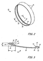
- FIG. 2 is a perspective view of splitter fairing 26 of a turbine engine 10.
- Splitter fairing 26 is generally cylindrical or frustaconical in shape and includes a forward portion 30, a body 32, and an aft portion 34 containing several apertures 36.
- Splitter fairing 26 is typically constructed from aluminum or similar light weight metal, including AL 6061.
- Splitter fairing 26 is a forged component of turbine engine 10; forging assures structural strength for the part.
- Splitter fairing 26 operates in an environment of minimally enhanced temperatures, typically operating at just slightly above ambient temperature.
- Forward portion 30 contains a front edge 38, which is used to direct the flow of fluids.
- Front edge 38 is forged in an acute angle, and may contain a rounded fillet to facilitate smooth air flow.
- Aft portion 34 is used to connect the splitter fairing 26 to the inner casing of the turbine engine 10.
- Apertures 36 are fastener holes for securing the splitter fairing 26 within the turbine engine 10.
- FIG. 3 is a cross-sectional view of splitter fairing 26 taken along line 3-3 illustrated in FIG. 2 .
- the aft portion 34 is illustrated as being thicker than the adjacent body 32. The additional thickness provides support for the apertures 36.
- Aperture 36 contains a hole 40 and a countersink 42. Countersink 42 allows for placing a fastener into the aperture 36 while keeping a flush surface along the splitter fairing 26. A smooth surface promotes fluid flow through the bypass duct 27.
- Aft portion 34 also contains an inner surface 44 perpendicular to the hole 40.
- Forward portion 30 has a hook shape with an inner flange 46 and an outer edge 48.
- the space between the inner flange 46 and outer edge 48 is used to attach low pressure compressor components.
- Forward portion 30 has general dimensions of height h and width w.
- an aft edge 50 of the inner flange 46 contains damage that must be remedied.
- splitting fairing 26 is removed from turbine engine 10. Forward portion 30 of the splitter fairing 26 is then removed along a line 49 by a process such as laser cutting or machining, or similar material removal methods known in the art. The cut is made along a line such as line 49. The angle of the cut is derived from the geometry of a replacement piece that will be attached to the remaining portion of splitter fairing 26.
- FIG. 4 is a perspective view of the splitter fairing 26 with the forward portion 30 removed, leaving an original portion 54, which contains the majority of body 32 and aft portion 34 with the apertures 36. Also illustrated is a replacement ring 56.
- Replacement ring 56 is constructed from the same or similar material as the original portion 54, such as AL 6061. Replacement ring may be a forged part.
- FIG. 5 is a cross-sectional view of the original portion 54 of splitter fairing 26 joined to replacement ring 56.
- Replacement ring 56 has a height H and width W, which are greater than the dimensions h and w of the original forward portion 30.
- Replacement ring 56 is welded to the original portion 54.
- FIG. 6 is a cross-sectional view of a repaired forward portion 30 of the splitter fairing 26.
- Replacement ring 56 has been machined down to obtain the original dimensions for the forward portion 30, including the inner flange 46 and outer edge 48. The machining also creates a channel 60 which allows for the attachment of low pressure compressor components to the splitter fairing 26.
- Inner flange 46 contains a round fillet on aft edge 50, which promotes fluid flow past the surface.
- the splitter fairing 26 is removed from the turbine engine.
- the damage is located during regular maintenance and inspection of the engine.
- the damaged section forward section is removed by machining or a similar process. Measurements are taken and recorded for the average wall thickness, inner diameter, and overall axial height to cut-off. Material removal is kept to a minimum.
- the cut plane location illustrated in FIG. 3 is placed to accommodate a second section replacement, should one be necessary in the future.
- the fairing is cleaned and the surfaces are prepped for welding by machining the original portion to a bright metal condition. Measurements are taken and recorded for the average wall thickness, inner diameter, and overall axial height to cut-off.
- a locally manufactured replacement ring is fabricated.
- the replacement ring is welded to the original portion by a welding process such electron beam (EB) welding, plasma arc welding (PAW), or gas tungsten arc welding (GTAW).
- EB electron beam
- PAW plasma arc welding
- GTAW gas tungsten arc welding
- the replacement ring is cleaned after machining, and nondestructive inspection, such as Fluorescent Penetrant Inspection (FPI) is performed on the replacement ring and original portion to assure no defects are present prior to welding.
- FPI Fluorescent Penetrant Inspection
- the weld is performed. After welding, a visual inspection of the weld joint is done to assess is any re-welding operations that must be performed. If re-welding is required, no more than 25% of the length of the weld should be redone. If more that 25% of the length required rewelding, the repair process should be started again.
- NDI nondestructive inspection
- FPI flourescent penetrant inspection
- ultrasonic inspection ultrasonic inspection
- x ray inspection etc.
- the replacement ring and adjacent weld are machined to meet the original tolerances of the part.
- the machining assures incorporation of critical design features present in the original section of the part.
- the original hole and perpendicular edge can be used as datum points for determining the amount of material to remove.
- the attaching weld must be flush to 0.010 inch (0.254 mm) above adjacent parent material.
- the original surface treatment on the part is removed, and a new surface treatment is applied.
- the part is again cleaned.
- the part is measured to assure all dimensions are within tolerances. The part is then ultimately returned to the engine.
- the current repair will not degrade the fatigue life of the part, and thus the life of the part is renewed with the forward section replacement.
- the fatigue life of the repaired part with the replacement ring and original section is substantially restored to that of the original part.
- the repair eliminates the need for replacement with a new part, which is more costly that utilizing the aforementioned repair.
Landscapes
- Engineering & Computer Science (AREA)
- Mechanical Engineering (AREA)
- General Engineering & Computer Science (AREA)
- Chemical & Material Sciences (AREA)
- Combustion & Propulsion (AREA)
- Laser Beam Processing (AREA)
- Turbine Rotor Nozzle Sealing (AREA)
- Arc Welding In General (AREA)
Abstract

Description
- The present invention relates to the repair of turbine engine components, and in particular but not exclusively to the repair of the front portion of a splitter fairing section located at the front of the low pressure compressor.
- During operation of a turbine engine, the engine components can be damaged. Engine operating stresses frequently lead to fatigue cracks or similar defects in gas turbine engines parts. Repairs must be done to the defects caused during normal operation. One part that may require repair is the splitter fairing. The splitter fairing supports the first stage stators of the low pressure compressor. Particularly, the front hook section as an engagement groove for the airseal on the splitter fairing can become worn. The inner flange of the hook becomes damaged, and must be repaired so that the part can function as originally anticipated.
- Traditional repair techniques, such as weld build up or plasma coating of the groove, are difficult to perform. Also, such repairs impose a debit to the structural capability, which will produce a repair with properties inferior to the original part. Currently, there is no known repair for the splitter fairing of an engine that assures the part will be restored to serviceable condition and airworthiness standards. The entire part is replaced. Replacement is done to assure part integrity. However, the cost associated with replacement is large. What is absent in the art is a repair that eliminates the need for total part replacement.
- In one embodiment, a defect in a splitter fairing of a turbine engine is repaired. A forward portion of the splitter fairing, the forward portion comprising an inner flange and outer surface that create a channel, is removed. An original portion of the splitter fairing is salvaged. A replacement ring is welded to the original portion. Material from the replacement ring is removed to obtain a profile with essentially the same profile for the inner flange, outer surface, and channel as the original dimensions of the splitter fairing before the defect occurred.
- In another embodiment, a defect in a generally cylindrical component turbine engine component is repaired. The component is removed from the engine, and a generally hook-shaped forward portion of the component is removed. A replacement ring having minimum dimensions equal to the maximum height and width of the removed forward portion is welded to the original portion. Material from the replacement ring is removed to obtain a new hook-shaped forward portion with essentially the same profile as the generally hook-shaped forward portion of the component prior to the defect.
-
-
FIG. 1 is a cross-sectional view of a gas turbine engine. -
FIG. 2 is a perspective view of a splitter fairing of a turbine engine. -
FIG. 3 is a cross-sectional view of the splitter fairing taken along line 3-3 illustrated inFIG. 2 . -
FIG. 4 is a perspective view of the splitter fairing with a front portion removed, along with a replacement ring. -
FIG. 5 is a cross-sectional view of the remaining portion of the front splitter fairing joined to the replacement ring. -
FIG. 6 is a cross-sectional view of the repaired portion of the splitter fairing ring. -
FIG. 1 is a cross-sectional view of agas turbine engine 10.Engine 10 has aninlet fan 12, acompressor section 14, acombustion section 16, and aturbine section 18.Compressor section 14 has alow pressure compressor 20 and ahigh pressure compressor 22. Air is taken in throughfan inlet 12 and a portion is directed to thecompressor section 14. The air is then compressed by a series of rotating blades and static vanes in the compressor section. The compressed air is mixed with fuel, and then ignited in thecombustion section 16. The combustion exhaust is then directed towards theturbine section 18, which is also comprised of blades and vanes. The blades extract kinetic energy from the exhaust to turn ashaft 24, which provides power output for the engine. - After air enters the
fan inlet 12, splitter fairing 26 directs a portion to thelow pressure compressor 20. The rest of the air flows through abypass duct 27. The air frombypass duct 27 will be bled off through anopening 28 to be used for cooling the components of thehigh pressure compressor 22,combustion section 16, andturbine section 18. -
FIG. 2 is a perspective view ofsplitter fairing 26 of aturbine engine 10.Splitter fairing 26 is generally cylindrical or frustaconical in shape and includes aforward portion 30, abody 32, and anaft portion 34 containingseveral apertures 36.Splitter fairing 26 is typically constructed from aluminum or similar light weight metal, including AL 6061.Splitter fairing 26 is a forged component ofturbine engine 10; forging assures structural strength for the part. Splitterfairing 26 operates in an environment of minimally enhanced temperatures, typically operating at just slightly above ambient temperature. -
Forward portion 30 contains afront edge 38, which is used to direct the flow of fluids.Front edge 38 is forged in an acute angle, and may contain a rounded fillet to facilitate smooth air flow.Aft portion 34 is used to connect thesplitter fairing 26 to the inner casing of theturbine engine 10.Apertures 36 are fastener holes for securing thesplitter fairing 26 within theturbine engine 10. -
FIG. 3 is a cross-sectional view ofsplitter fairing 26 taken along line 3-3 illustrated inFIG. 2 . In this view, theaft portion 34 is illustrated as being thicker than theadjacent body 32. The additional thickness provides support for theapertures 36. Aperture 36 contains ahole 40 and acountersink 42. Countersink 42 allows for placing a fastener into theaperture 36 while keeping a flush surface along thesplitter fairing 26. A smooth surface promotes fluid flow through thebypass duct 27.Aft portion 34 also contains aninner surface 44 perpendicular to thehole 40. -
Forward portion 30 has a hook shape with aninner flange 46 and anouter edge 48. The space between theinner flange 46 andouter edge 48 is used to attach low pressure compressor components.Forward portion 30 has general dimensions of height h and width w. In the embodiment illustrated, anaft edge 50 of theinner flange 46 contains damage that must be remedied. - To initiate the repair, the splitting fairing 26 is removed from
turbine engine 10.Forward portion 30 of the splitter fairing 26 is then removed along a line 49 by a process such as laser cutting or machining, or similar material removal methods known in the art. The cut is made along a line such as line 49. The angle of the cut is derived from the geometry of a replacement piece that will be attached to the remaining portion of splitter fairing 26. -
FIG. 4 is a perspective view of the splitter fairing 26 with theforward portion 30 removed, leaving anoriginal portion 54, which contains the majority ofbody 32 andaft portion 34 with theapertures 36. Also illustrated is areplacement ring 56.Replacement ring 56 is constructed from the same or similar material as theoriginal portion 54, such as AL 6061. Replacement ring may be a forged part. -
FIG. 5 is a cross-sectional view of theoriginal portion 54 of splitter fairing 26 joined toreplacement ring 56.Replacement ring 56 has a height H and width W, which are greater than the dimensions h and w of theoriginal forward portion 30.Replacement ring 56 is welded to theoriginal portion 54. -
FIG. 6 is a cross-sectional view of a repairedforward portion 30 of thesplitter fairing 26.Replacement ring 56 has been machined down to obtain the original dimensions for theforward portion 30, including theinner flange 46 andouter edge 48. The machining also creates achannel 60 which allows for the attachment of low pressure compressor components to thesplitter fairing 26.Inner flange 46 contains a round fillet onaft edge 50, which promotes fluid flow past the surface. - To summarize the repair process, the splitter fairing 26 is removed from the turbine engine. The damage is located during regular maintenance and inspection of the engine. The damaged section forward section is removed by machining or a similar process. Measurements are taken and recorded for the average wall thickness, inner diameter, and overall axial height to cut-off. Material removal is kept to a minimum. The cut plane location illustrated in
FIG. 3 is placed to accommodate a second section replacement, should one be necessary in the future. - Next, the fairing is cleaned and the surfaces are prepped for welding by machining the original portion to a bright metal condition. Measurements are taken and recorded for the average wall thickness, inner diameter, and overall axial height to cut-off.
- A locally manufactured replacement ring is fabricated. The replacement ring is welded to the original portion by a welding process such electron beam (EB) welding, plasma arc welding (PAW), or gas tungsten arc welding (GTAW). If the EB procedure is to be performed, the locally fabricated replacement ring is machined ensuring a proper EB joint fit-up of 0.003 inch (0.076 mm) maximum gap. Similarly, if PAW procedure is to be performed, the replacement ring is fabricated to ensure a proper PAW joint fit. If GTAW is performed, additional filler material may be required.
- The replacement ring is cleaned after machining, and nondestructive inspection, such as Fluorescent Penetrant Inspection (FPI) is performed on the replacement ring and original portion to assure no defects are present prior to welding. The weld is performed. After welding, a visual inspection of the weld joint is done to assess is any re-welding operations that must be performed. If re-welding is required, no more than 25% of the length of the weld should be redone. If more that 25% of the length required rewelding, the repair process should be started again.
- A further inspection is done after the initial visual inspection. Known nondestructive inspection (NDI) techniques, such as flourescent penetrant inspection (FPI), eddy current inspection, ultrasonic inspection and x ray inspection, etc. can be used. After inspection, the part is stress-relieved if needed. Also, heat treatment may be applied to the completed part.
- Next, the replacement ring and adjacent weld are machined to meet the original tolerances of the part. The machining assures incorporation of critical design features present in the original section of the part. The original hole and perpendicular edge can be used as datum points for determining the amount of material to remove. The attaching weld must be flush to 0.010 inch (0.254 mm) above adjacent parent material. The original surface treatment on the part is removed, and a new surface treatment is applied. The part is again cleaned. Finally, the part is measured to assure all dimensions are within tolerances. The part is then ultimately returned to the engine.
- The current repair will not degrade the fatigue life of the part, and thus the life of the part is renewed with the forward section replacement. The fatigue life of the repaired part with the replacement ring and original section is substantially restored to that of the original part. The repair eliminates the need for replacement with a new part, which is more costly that utilizing the aforementioned repair.
- Although the present invention has been described with reference to preferred embodiments, workers skilled in the art will recognize that changes may be made in form and detail without departing from the scope of the invention.
Claims (11)
- A method of repairing a defect in a splitter fairing (26) of a turbine engine (10), the method comprising:removing a forward portion (30) of the splitter fairing (26), the forward portion (30) comprising an inner flange (46) and outer surface that create a channel, wherein an original portion (54) of the splitter fairing (26) is salvaged;welding a replacement ring (56) to the original portion (54), the replacement ring (56) having minimum dimensions equal to the maximum height and width of the removed forward portion (30);removing material from the replacement ring (56) to obtain a profile with essentially the same profile for the inner flange, outer surface, and channel as the original specifications for the splitter fairing (26).
- The method of claim 1 wherein the original portion (54) of the splitter fairing (26) contains a series of apertures (36) that are generally perpendicular to an outer surface of an aft portion (34) of the splitter fairing (26).
- The method of claim 2 further comprising:using the apertures (36) and adjacent outer surfaces as datum points for the machining process.
- A method of repairing a defect in a generally cylindrical component (26) of a turbine engine (10), the component containing a generally hook-shaped forward portion (30), the method comprising:removing the component (26) from the engine;removing the forward portion (30) of the component (26), leaving an original portion (54) of the component intact;welding a replacement ring (56) to the original portion (54), the replacement ring (56) having minimum dimensions equal to the maximum height and width of the removed forward portion (30);removing material from the replacement ring (54) to obtain a new hook-shaped forward portion with essentially the same profile as the generally hook-shaped forward portion (30) as detailed by the original part specifications.
- The method of any preceding claim wherein the replacement ring (56) contains similar metallurgical properties to the base material.
- The method of any of claims 1 to 4 wherein the replacement ring (56) contains essentially the same metallurgical properties as the base material.
- The method of any preceding claim wherein the welding process used is electron beam welding.
- The method of any of claims 1 to 6 wherein the welding process used is plasma arc welding.
- The method of any of claims 1 to 6 wherein the welding process used is gas tungsten arc welding
- The method of any preceding claim further comprising:inspecting the repair to assure the repair has essentially the same dimensions as the original component.
- The method of any preceding claim wherein removing the forward portion (30) is done by machining.
Applications Claiming Priority (1)
| Application Number | Priority Date | Filing Date | Title |
|---|---|---|---|
| US11/714,750 US20080216300A1 (en) | 2007-03-06 | 2007-03-06 | Splitter fairing repair |
Publications (2)
| Publication Number | Publication Date |
|---|---|
| EP1967693A2 true EP1967693A2 (en) | 2008-09-10 |
| EP1967693A3 EP1967693A3 (en) | 2012-01-18 |
Family
ID=39363977
Family Applications (1)
| Application Number | Title | Priority Date | Filing Date |
|---|---|---|---|
| EP08250741A Withdrawn EP1967693A3 (en) | 2007-03-06 | 2008-03-05 | Splitter fairing repair |
Country Status (3)
| Country | Link |
|---|---|
| US (1) | US20080216300A1 (en) |
| EP (1) | EP1967693A3 (en) |
| SG (1) | SG145680A1 (en) |
Cited By (3)
| Publication number | Priority date | Publication date | Assignee | Title |
|---|---|---|---|---|
| EP2039882A3 (en) * | 2007-09-12 | 2012-03-14 | United Technologies Corporation | Methods for performing gas turbine engine casing repairs and repaired cases |
| EP2472070A3 (en) * | 2010-12-30 | 2014-06-04 | Rolls-Royce Corporation | Methods of manufacturing a gas turbine engine case and corresponding case |
| EP3361060A1 (en) * | 2017-02-13 | 2018-08-15 | General Electric Technology GmbH | Cooling systems for cavities between inner and outer casings |
Families Citing this family (28)
| Publication number | Priority date | Publication date | Assignee | Title |
|---|---|---|---|---|
| DE102008060489A1 (en) * | 2008-12-05 | 2010-06-10 | Rolls-Royce Deutschland Ltd & Co Kg | Flow divider for a fan engine |
| US8563079B2 (en) * | 2009-06-08 | 2013-10-22 | United Technologies Corporation | Plastic welding using fiber reinforcement materials |
| US8987632B2 (en) * | 2009-10-09 | 2015-03-24 | The United States Of America As Represented By The Administrator Of The National Aeronautics And Space Administration | Modification of surface energy via direct laser ablative surface patterning |
| US9278374B2 (en) | 2012-06-08 | 2016-03-08 | The United States Of America As Represented By The Administrator Of The National Aeronautics And Space Administration | Modified surface having low adhesion properties to mitigate insect residue adhesion |
| US9903224B2 (en) | 2012-12-29 | 2018-02-27 | United Technologies Corporation | Scupper channelling in gas turbine modules |
| WO2014105619A1 (en) | 2012-12-29 | 2014-07-03 | United Technologies Corporation | Multi-function boss for a turbine exhaust case |
| US10240532B2 (en) | 2012-12-29 | 2019-03-26 | United Technologies Corporation | Frame junction cooling holes |
| EP2938868B1 (en) | 2012-12-29 | 2019-08-07 | United Technologies Corporation | Flow diverter assembly |
| WO2014105800A1 (en) | 2012-12-29 | 2014-07-03 | United Technologies Corporation | Gas turbine seal assembly and seal support |
| US10053998B2 (en) | 2012-12-29 | 2018-08-21 | United Technologies Corporation | Multi-purpose gas turbine seal support and assembly |
| WO2014105599A1 (en) | 2012-12-29 | 2014-07-03 | United Technologies Corporation | Heat shield for cooling a strut |
| WO2014137444A2 (en) | 2012-12-29 | 2014-09-12 | United Technologies Corporation | Multi-ply finger seal |
| WO2014105100A1 (en) | 2012-12-29 | 2014-07-03 | United Technologies Corporation | Bumper for seals in a turbine exhaust case |
| WO2014105616A1 (en) | 2012-12-29 | 2014-07-03 | United Technologies Corporation | Turbine exhaust case architecture |
| JP6271582B2 (en) | 2012-12-29 | 2018-01-31 | ユナイテッド テクノロジーズ コーポレイションUnited Technologies Corporation | Gas turbine seal assembly and seal support |
| WO2014105603A1 (en) | 2012-12-29 | 2014-07-03 | United Technologies Corporation | Multi-piece heat shield |
| WO2014105602A1 (en) | 2012-12-29 | 2014-07-03 | United Technologies Corporation | Heat shield for a casing |
| DE112013006258B4 (en) | 2012-12-29 | 2026-01-15 | RTX Corporation (n.d.Ges.d. Staates Delaware) | Turbine frame arrangement and method for providing a turbine frame arrangement |
| WO2014105604A1 (en) | 2012-12-29 | 2014-07-03 | United Technologies Corporation | Angled cut to direct radiative heat load |
| WO2014105657A1 (en) | 2012-12-29 | 2014-07-03 | United Technologies Corporation | Mount with deflectable tabs |
| EP2938863B1 (en) | 2012-12-29 | 2019-09-25 | United Technologies Corporation | Mechanical linkage for segmented heat shield |
| EP2938836B1 (en) | 2012-12-29 | 2020-02-05 | United Technologies Corporation | Seal support disk and assembly |
| JP6249499B2 (en) | 2012-12-31 | 2017-12-20 | ユナイテッド テクノロジーズ コーポレイションUnited Technologies Corporation | Multi-piece frame for turbine exhaust case |
| WO2014105716A1 (en) | 2012-12-31 | 2014-07-03 | United Technologies Corporation | Turbine exhaust case multi-piece frame |
| EP2938860B1 (en) | 2012-12-31 | 2018-08-29 | United Technologies Corporation | Turbine exhaust case multi-piece frame |
| US10330011B2 (en) | 2013-03-11 | 2019-06-25 | United Technologies Corporation | Bench aft sub-assembly for turbine exhaust case fairing |
| US10233780B2 (en) | 2013-07-11 | 2019-03-19 | United Technologies Corporation | Flange partial section replacement repair |
| GB201705734D0 (en) * | 2017-04-10 | 2017-05-24 | Rolls Royce Plc | Flow splitter |
Family Cites Families (14)
| Publication number | Priority date | Publication date | Assignee | Title |
|---|---|---|---|---|
| US3449816A (en) * | 1967-04-24 | 1969-06-17 | Dwain K Swick | Method of repairing screw-in precombustion chamber type openings in cylinder heads |
| US5205465A (en) * | 1990-09-19 | 1993-04-27 | United Technologies Corporation | Method for replacing worn airseal lands on engine compressor or turbine disks |
| US6301780B1 (en) * | 1998-09-16 | 2001-10-16 | Positech International, Inc. | Method for recording an aviation oil cooler |
| US6128820A (en) * | 1998-10-20 | 2000-10-10 | General Electric Co. | Method of repairing damaged turbine rotor wheels using differentially controlled temperatures |
| US6607114B2 (en) * | 2001-10-12 | 2003-08-19 | General Electric Company | Weld fixture and method for repairing annular components |
| US6892931B2 (en) * | 2002-12-27 | 2005-05-17 | General Electric Company | Methods for replacing portions of turbine shroud supports |
| US6779268B1 (en) * | 2003-05-13 | 2004-08-24 | General Electric Company | Outer and inner cowl-wire wrap to one piece cowl conversion |
| US20050102835A1 (en) * | 2003-11-14 | 2005-05-19 | Trewiler Gary E. | Method for repairing gas turbine rotor blades |
| US20050172485A1 (en) * | 2004-02-10 | 2005-08-11 | Ramsay Mussen | Method of repair for cast article |
| US6969826B2 (en) * | 2004-04-08 | 2005-11-29 | General Electric Company | Welding process |
| FR2871399B1 (en) * | 2004-06-15 | 2006-09-22 | Snecma Moteurs Sa | PROCESS FOR REPAIRING A DAWN ELEMENT |
| US7546684B2 (en) * | 2004-07-27 | 2009-06-16 | General Electric Company | Method for repair and replacement of combustor liner panel |
| US7278829B2 (en) * | 2005-02-09 | 2007-10-09 | General Electric Company | Gas turbine blade having a monocrystalline airfoil with a repair squealer tip, and repair method |
| US7850173B2 (en) * | 2006-08-31 | 2010-12-14 | Pratt & Whitney Canada Corp. | Repairable labyrinth seal |
-
2007
- 2007-03-06 US US11/714,750 patent/US20080216300A1/en not_active Abandoned
-
2008
- 2008-03-05 EP EP08250741A patent/EP1967693A3/en not_active Withdrawn
- 2008-03-05 SG SG200801852-5A patent/SG145680A1/en unknown
Cited By (4)
| Publication number | Priority date | Publication date | Assignee | Title |
|---|---|---|---|---|
| EP2039882A3 (en) * | 2007-09-12 | 2012-03-14 | United Technologies Corporation | Methods for performing gas turbine engine casing repairs and repaired cases |
| US9765622B2 (en) | 2007-09-12 | 2017-09-19 | United Technologies Corporation | Methods for performing gas turbine engine casing repairs and repaired cases |
| EP2472070A3 (en) * | 2010-12-30 | 2014-06-04 | Rolls-Royce Corporation | Methods of manufacturing a gas turbine engine case and corresponding case |
| EP3361060A1 (en) * | 2017-02-13 | 2018-08-15 | General Electric Technology GmbH | Cooling systems for cavities between inner and outer casings |
Also Published As
| Publication number | Publication date |
|---|---|
| US20080216300A1 (en) | 2008-09-11 |
| EP1967693A3 (en) | 2012-01-18 |
| SG145680A1 (en) | 2008-09-29 |
Similar Documents
| Publication | Publication Date | Title |
|---|---|---|
| EP1967693A2 (en) | Splitter fairing repair | |
| US7959409B2 (en) | Repaired vane assemblies and methods of repairing vane assemblies | |
| US6416278B1 (en) | Turbine nozzle segment and method of repairing same | |
| US6793457B2 (en) | Fabricated repair of cast nozzle | |
| US7858897B2 (en) | Insert weld repair | |
| US7980813B2 (en) | Fan outlet guide vane shroud insert repair | |
| US8257039B2 (en) | Gas turbine engine case with replaced flange and method of repairing the same using cold metal transfer | |
| US20170009584A1 (en) | Systems and Methods for Turbine Blade Repair | |
| EP2116691A2 (en) | Method for repairing a gas turbine engine component | |
| CN110234837A (en) | The method for repairing integral blade disk | |
| US9694440B2 (en) | Support collar geometry for linear friction welding | |
| US6892931B2 (en) | Methods for replacing portions of turbine shroud supports | |
| US20170167263A1 (en) | Systems and methods for deep tip crack repair | |
| JP2005201242A (en) | How to repair a gas turbine rotor blade | |
| US7837437B2 (en) | Turbine nozzle segment and repair method | |
| JP2006170204A (en) | Turbine nozzle segment and repair method thereof | |
| US20180126499A1 (en) | Threaded coupon for repair of superalloy part | |
| EP1564371A2 (en) | Method of repair for cast article | |
| NL2002340C2 (en) | Method for repairing a cooled turbine nozzle segment. | |
| US10563533B2 (en) | Repair or remanufacture of blade outer air seals for a gas turbine engine |
Legal Events
| Date | Code | Title | Description |
|---|---|---|---|
| PUAI | Public reference made under article 153(3) epc to a published international application that has entered the european phase |
Free format text: ORIGINAL CODE: 0009012 |
|
| AK | Designated contracting states |
Kind code of ref document: A2 Designated state(s): AT BE BG CH CY CZ DE DK EE ES FI FR GB GR HR HU IE IS IT LI LT LU LV MC MT NL NO PL PT RO SE SI SK TR |
|
| AX | Request for extension of the european patent |
Extension state: AL BA MK RS |
|
| PUAL | Search report despatched |
Free format text: ORIGINAL CODE: 0009013 |
|
| AK | Designated contracting states |
Kind code of ref document: A3 Designated state(s): AT BE BG CH CY CZ DE DK EE ES FI FR GB GR HR HU IE IS IT LI LT LU LV MC MT NL NO PL PT RO SE SI SK TR |
|
| AX | Request for extension of the european patent |
Extension state: AL BA MK RS |
|
| RIC1 | Information provided on ipc code assigned before grant |
Ipc: F02K 3/06 20060101ALI20111215BHEP Ipc: F01D 5/00 20060101AFI20111215BHEP |
|
| 17P | Request for examination filed |
Effective date: 20120718 |
|
| AKX | Designation fees paid |
Designated state(s): DE GB |
|
| STAA | Information on the status of an ep patent application or granted ep patent |
Free format text: STATUS: THE APPLICATION HAS BEEN WITHDRAWN |
|
| 18W | Application withdrawn |
Effective date: 20150113 |