EP1967399A1 - A connector device for an AC condenser and a vehicle - Google Patents
A connector device for an AC condenser and a vehicle Download PDFInfo
- Publication number
- EP1967399A1 EP1967399A1 EP08102241A EP08102241A EP1967399A1 EP 1967399 A1 EP1967399 A1 EP 1967399A1 EP 08102241 A EP08102241 A EP 08102241A EP 08102241 A EP08102241 A EP 08102241A EP 1967399 A1 EP1967399 A1 EP 1967399A1
- Authority
- EP
- European Patent Office
- Prior art keywords
- charge
- connector
- discharge
- bloc
- condenser
- Prior art date
- Legal status (The legal status is an assumption and is not a legal conclusion. Google has not performed a legal analysis and makes no representation as to the accuracy of the status listed.)
- Granted
Links
Images

Classifications
-
- B—PERFORMING OPERATIONS; TRANSPORTING
- B60—VEHICLES IN GENERAL
- B60H—ARRANGEMENTS OF HEATING, COOLING, VENTILATING OR OTHER AIR-TREATING DEVICES SPECIALLY ADAPTED FOR PASSENGER OR GOODS SPACES OF VEHICLES
- B60H1/00—Heating, cooling or ventilating devices
- B60H1/00321—Heat exchangers for air-conditioning devices
- B60H1/00328—Heat exchangers for air-conditioning devices of the liquid-air type
-
- F—MECHANICAL ENGINEERING; LIGHTING; HEATING; WEAPONS; BLASTING
- F28—HEAT EXCHANGE IN GENERAL
- F28F—DETAILS OF HEAT-EXCHANGE AND HEAT-TRANSFER APPARATUS, OF GENERAL APPLICATION
- F28F9/00—Casings; Header boxes; Auxiliary supports for elements; Auxiliary members within casings
- F28F9/02—Header boxes; End plates
- F28F9/0246—Arrangements for connecting header boxes with flow lines
-
- B—PERFORMING OPERATIONS; TRANSPORTING
- B60—VEHICLES IN GENERAL
- B60H—ARRANGEMENTS OF HEATING, COOLING, VENTILATING OR OTHER AIR-TREATING DEVICES SPECIALLY ADAPTED FOR PASSENGER OR GOODS SPACES OF VEHICLES
- B60H1/00—Heating, cooling or ventilating devices
- B60H1/00321—Heat exchangers for air-conditioning devices
- B60H1/00335—Heat exchangers for air-conditioning devices of the gas-air type
-
- B—PERFORMING OPERATIONS; TRANSPORTING
- B60—VEHICLES IN GENERAL
- B60H—ARRANGEMENTS OF HEATING, COOLING, VENTILATING OR OTHER AIR-TREATING DEVICES SPECIALLY ADAPTED FOR PASSENGER OR GOODS SPACES OF VEHICLES
- B60H1/00—Heating, cooling or ventilating devices
- B60H1/32—Cooling devices
- B60H1/3204—Cooling devices using compression
- B60H1/3227—Cooling devices using compression characterised by the arrangement or the type of heat exchanger, e.g. condenser, evaporator
-
- B—PERFORMING OPERATIONS; TRANSPORTING
- B60—VEHICLES IN GENERAL
- B60H—ARRANGEMENTS OF HEATING, COOLING, VENTILATING OR OTHER AIR-TREATING DEVICES SPECIALLY ADAPTED FOR PASSENGER OR GOODS SPACES OF VEHICLES
- B60H1/00—Heating, cooling or ventilating devices
- B60H1/32—Cooling devices
- B60H1/3204—Cooling devices using compression
- B60H1/3229—Cooling devices using compression characterised by constructional features, e.g. housings, mountings, conversion systems
-
- F—MECHANICAL ENGINEERING; LIGHTING; HEATING; WEAPONS; BLASTING
- F25—REFRIGERATION OR COOLING; COMBINED HEATING AND REFRIGERATION SYSTEMS; HEAT PUMP SYSTEMS; MANUFACTURE OR STORAGE OF ICE; LIQUEFACTION SOLIDIFICATION OF GASES
- F25B—REFRIGERATION MACHINES, PLANTS OR SYSTEMS; COMBINED HEATING AND REFRIGERATION SYSTEMS; HEAT PUMP SYSTEMS
- F25B2339/00—Details of evaporators; Details of condensers
- F25B2339/04—Details of condensers
- F25B2339/044—Condensers with an integrated receiver
- F25B2339/0442—Condensers with an integrated receiver characterised by the mechanical fixation of the receiver to the header
-
- F—MECHANICAL ENGINEERING; LIGHTING; HEATING; WEAPONS; BLASTING
- F25—REFRIGERATION OR COOLING; COMBINED HEATING AND REFRIGERATION SYSTEMS; HEAT PUMP SYSTEMS; MANUFACTURE OR STORAGE OF ICE; LIQUEFACTION SOLIDIFICATION OF GASES
- F25B—REFRIGERATION MACHINES, PLANTS OR SYSTEMS; COMBINED HEATING AND REFRIGERATION SYSTEMS; HEAT PUMP SYSTEMS
- F25B39/00—Evaporators; Condensers
- F25B39/04—Condensers
Definitions
- the present invention relates to a connector device according to the introductory portion of the attached claim 1.
- the invention also relates to a vehicle according to the attached claim 9.
- a condenser of the vehicle AC system is normally positioned in the front of the vehicle, behind a vehicle front cover.
- the condenser is provided with a charge connection and a discharge connection and a connector bloc receiving a charge pipe and a discharge pipe.
- a problem is the piping leading to and from the connector bloc.
- Today these pipes run to and from the connector bloc practically vertically and then further to the vehicle cabin and to the AC system compressor. This may cause wear of the pipes, which are partly of plastic or rubber, against the vehicle, the truck, front panel covering the condenser etc as well as unwanted vibrations, the space available behind the front panel being extremely limited in most trucks.
- the object of the present invention is to provide a solution to the problems described above and to provide a better total lay-out of the actual AC arrangement.
- the object of the present invention is obtained by means of a device and a vehicle according to claims 1 and 9, respectively.
- FIG. 1 showing a view over an AC condenser arrangement
- 1 designates an AC condenser, preferably having a flat and substantially rectangular configuration and being provided with a connection header 2 at a vertical side 3, a connector device 4 according to the invention being provided with and comprising a connector bloc 5 for transferring a charge gas flow 6 of a charge pipe 7, indicated by an arrow 6', to the condenser via an inlet opening 8 and an outlet opening 9, fig. 3 , of the connector bloc.
- the charge pipe 7 is a part of a piping running from a compressor 10, indicated in fig. 1 .
- the connector bloc is further for transferring a discharge liquid flow 11, indicated by an arrow 11', from the condenser via an inlet opening 12 and an outlet opening 13, fig. 3 , of the connector bloc to a discharge pipe 14, the discharge running to the vehicle cabin 15, indicated in fig. 1 .
- the charge pipe inlet opening 8 and the discharge pipe outlet opening 13 and the respective connecting pipe parts 8', 13', respectively, running thereto are arranged substantially in one plane substantially parallel to the main extension plane 16 of the condenser, the discharge outlet opening 13 being positioned between the charge inlet opening 8 and the condenser header.
- the connector bloc is arranged so that the charge gas flow 6 crosses the discharge liquid flow 11 in the connector bloc, without, of course, the two flows interfering with each other.
- the connector bloc comprises a charge channel 17, fig. 3 and 4 , running between the charge inlet opening and the charge outlet opening and a discharge channel 18 running between the discharge inlet opening and the discharge outlet opening, the discharge channel preferably running substantially straight through the connector bloc. Further, at least an outlet portion 17' of the charge channel runs in a direction crossing the discharge channel 18 direction.
- the charge inlet opening and the discharge outlet opening are positioned on top of the connector bloc, as can be seen in eg fig. 1 .
- the connector block is brazed to the condenser header, thereby connecting the charge outlet opening to the header.
- the discharge inlet opening of the connector bloc is connected to the header by means of a connection pipe 19, as can be seen in fig. 1 .
- connection piece 20 designates a connection piece preferably provided with and carrying two pre-formed, preferably metallic, connection pipe pieces 21, 22 for connecting the charge gas flow 6 with the charge inlet opening of the connector bloc and the discharge liquid flow 11 with the discharge outlet opening of the connector bloc respectively.
- connection piece 20 is releasably fixed to the connector bloc with one fastening element, preferably a nut or a bolt, not shown.
- the charge connection pipe piece comprises of least one bend 21' to make the pipe make a substantially 90° turn away from the condenser in relation to a pipe part 8' running to the charge inlet of the connector bloc.
- connection device has according to the invention been designed to extend in a substantially flat configuration substantially parallel to the main extension plane of the condenser, one of the main features being that the charge and discharge pipes do not cross each other but crossing of the charge gas flow and the discharge liquid flow occurs inside the connector bloc, which is provided with two separate channels 17, 18, which crosses each other without interfering with each other in the connector bloc and so that the charge flow is linked from the connector bloc side, turned from the condenser header, to the connector bloc side being turned to the condenser header and thus is directly connectable to the header and preferably to the header upper portion, which is normally the proper input for the charge gas flow into the condenser.
- the invention provides a solution to the problems described in the introductory portion of the present application.
- connection piece solution makes it possible to fasten the connection piece with only one fastening element and to amend the design of the connection pipe pieces using the same connector bloc.
Landscapes
- Engineering & Computer Science (AREA)
- Physics & Mathematics (AREA)
- Thermal Sciences (AREA)
- Mechanical Engineering (AREA)
- General Engineering & Computer Science (AREA)
- Air-Conditioning For Vehicles (AREA)
Abstract
Description
- The present invention relates to a connector device according to the introductory portion of the attached
claim 1. - The invention also relates to a vehicle according to the attached
claim 9. - In a vehicle, eg a truck, a condenser of the vehicle AC system is normally positioned in the front of the vehicle, behind a vehicle front cover.
- For charging and discharging, the condenser is provided with a charge connection and a discharge connection and a connector bloc receiving a charge pipe and a discharge pipe.
- A problem is the piping leading to and from the connector bloc. Today these pipes run to and from the connector bloc practically vertically and then further to the vehicle cabin and to the AC system compressor. This may cause wear of the pipes, which are partly of plastic or rubber, against the vehicle, the truck, front panel covering the condenser etc as well as unwanted vibrations, the space available behind the front panel being extremely limited in most trucks.
- Further, this normally causes the need of considerable pipe lengths between, inter alia, the connector bloc and the compressor due to the compressor location, this piping consuming space in an unwanted way.
- To solve these problems in view of the general lay-out of the condenser/connector bloc/compressor-arrangement it would be desirable to lead the pipe running between the connector bloc and the compressor sideways from the connector bloc and then further backwards in the longitudinal direction of the vehicle to the compressor. This pipe would then have to cross the other pipe to get to the condenser, which is however not possible due to lack of space between the connector bloc, the pipes and the front panel.
- The object of the present invention is to provide a solution to the problems described above and to provide a better total lay-out of the actual AC arrangement.
- The object of the present invention is obtained by means of a device and a vehicle according to
claims - Further advantages are obtained by what is specified in the dependent claims.
- A better understanding of the invention should be had from the following detailed description read in conjunction with the attached drawings, in which
-
Fig. 1 schematically shows in a perspective view an AC condenser arrangement provided with a first embodiment of a connector device according to the present invention, -
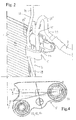
Fig. 2 schematically shows a connector device according tofig. 1 in more detail, -
Fig. 3 schematically shows a front view of a connector bloc according to the present invention and -
Fig. 4 schematically shows a view from above infig. 3 of the connector bloc according to the invention. - In
fig. 1 , showing a view over an AC condenser arrangement, 1 designates an AC condenser, preferably having a flat and substantially rectangular configuration and being provided with aconnection header 2 at avertical side 3, a connector device 4 according to the invention being provided with and comprising a connector bloc 5 for transferring a charge gas flow 6 of a charge pipe 7, indicated by an arrow 6', to the condenser via aninlet opening 8 and anoutlet opening 9,fig. 3 , of the connector bloc. The charge pipe 7 is a part of a piping running from acompressor 10, indicated infig. 1 . The connector bloc is further for transferring a discharge liquid flow 11, indicated by an arrow 11', from the condenser via aninlet opening 12 and an outlet opening 13,fig. 3 , of the connector bloc to adischarge pipe 14, the discharge running to thevehicle cabin 15, indicated infig. 1 . - The charge pipe inlet opening 8 and the discharge pipe outlet opening 13 and the respective connecting pipe parts 8', 13', respectively, running thereto are arranged substantially in one plane substantially parallel to the main extension plane 16 of the condenser, the discharge outlet opening 13 being positioned between the charge inlet opening 8 and the condenser header.
- According to the invention the connector bloc is arranged so that the charge gas flow 6 crosses the discharge liquid flow 11 in the connector bloc, without, of course, the two flows interfering with each other.
- According to preferred embodiments the connector bloc comprises a
charge channel 17,fig. 3 and4 , running between the charge inlet opening and the charge outlet opening and adischarge channel 18 running between the discharge inlet opening and the discharge outlet opening, the discharge channel preferably running substantially straight through the connector bloc. Further, at least an outlet portion 17' of the charge channel runs in a direction crossing thedischarge channel 18 direction. - Further, according to preferred embodiments the charge inlet opening and the discharge outlet opening are positioned on top of the connector bloc, as can be seen in eg
fig. 1 . - Preferred is that the connector block is brazed to the condenser header, thereby connecting the charge outlet opening to the header.
- Also preferred is that the discharge inlet opening of the connector bloc is connected to the header by means of a
connection pipe 19, as can be seen infig. 1 . - 20 designates a connection piece preferably provided with and carrying two pre-formed, preferably metallic,
connection pipe pieces - According to preferred embodiments the
connection piece 20 is releasably fixed to the connector bloc with one fastening element, preferably a nut or a bolt, not shown. - Preferred is also that the charge connection pipe piece comprises of least one bend 21' to make the pipe make a substantially 90° turn away from the condenser in relation to a pipe part 8' running to the charge inlet of the connector bloc.
- The function of the connector device should to a considerable and sufficient extent have been made clear from the description given above.
- Thus, in order to meet the demands that the lack of space in the front of the vehicle behind the front cover put on the connection arrangement for the AC condenser, the connection device has according to the invention been designed to extend in a substantially flat configuration substantially parallel to the main extension plane of the condenser, one of the main features being that the charge and discharge pipes do not cross each other but crossing of the charge gas flow and the discharge liquid flow occurs inside the connector bloc, which is provided with two
separate channels - The invention provides a solution to the problems described in the introductory portion of the present application.
- According to the normal lay-out of the condenser arrangement it is advantageous to draw the piping from the compressor in the longitudinal direction of the vehicle and then sideways to the connector block to forward the charge gas flow to the condenser. This is made possible by means of the present invention in spite of an extreme lack of space in the front behind the front cover, the lack of space being, inter alia, due to the vehicle motor location, which is not easy to amend but rather impossible under the circumstances.
- The specific embodiment shown offers other advantages. Thus, the connection piece solution makes it possible to fasten the connection piece with only one fastening element and to amend the design of the connection pipe pieces using the same connector bloc.
- Above, the invention has been described in association with preferred embodiments and examples.
- Of course, further embodiments as well as minor amendments and complementary additions may be imagined.
- Thus, embodiments may be imagined, in which the charge pipe runs to the side of the connector bloc and hereby to the connector bloc side being turned from the condenser and the header and, thus, runs substantially perpendicular to the header main extension direction. This configuration is adapted to a charge piping running from the compressor in the longitudinal direction of the vehicle and then sideways to the connector bloc.
- The invention should not be considered to be limited to the embodiments shown but may be varied within the scope of the appended claims.
Claims (9)
- A connector device for an AC condenser comprising a connection header and a connector bloc for transferring a charge gas flow of a charge pipe to the condenser via an inlet opening and an outlet opening of the connector bloc and for transferring a discharge liquid flow from the condenser via an inlet opening and an outlet opening to a discharge pipe, the charge inlet opening and the discharge outlet opening and the respective connecting pipe parts running thereto being arranged substantially in one plane substantially parallel to the main extension plane of the condenser, the discharge outlet opening being positioned between the charge inlet opening and the condenser header, characterized in that the connector bloc (5) is arranged so that the charge gas flow (6) crosses the discharge liquid flow (11) in the connector bloc.
- A device according to claim 1, wherein the charge inlet opening (8) and the discharge outlet opening (13) are positioned on top of the connector bloc.
- A device according to claim 1 or 2, wherein the connector bloc comprises a charge channel (17) running between the charge inlet opening (8) and the charge outlet opening (9) and a discharge channel running between the discharge inlet opening (12) and the discharge outlet opening (13), the discharge channel (18) running substantially straight through the connector bloc, at least an outlet portion (17') of the charge channel running in a direction crossing the discharge channel direction.
- A device according to claim 1, 2 or 3, wherein the connector bloc is brazed to the header (2) thereby connecting the charge outlet opening to the header.
- A device according to claim 1, 2, 3 or 4, wherein the discharge inlet opening (12) of the connector bloc is connected to the header by means of a connection pipe (19).
- A device according to claim 1, 2, 3, 4 or 5, wherein a connection piece is provided carrying two pre-formed, preferably metallic, connection pipe pieces (21, 22) for connecting the charge gas flow with the charge inlet opening of the connector bloc and the discharge liquid flow (11) with the discharge outlet opening of the connector bloc, respectively.
- A device according to claim 6, wherein the connection piece is releaseably fixed to the connector bloc with one fastening element, preferably a nut or a bolt.
- A device according to claim 6, wherein the charge connection pipe piece comprises at least one bend (21') to make the pipe make a substantially 90° turn away from the condenser in relation to a pipe part (18') running to the charge inlet opening of the connector bloc.
- A vehicle, preferably a truck, characterized in that it comprises a connector device according to anyone of claims 1-8.
Applications Claiming Priority (1)
| Application Number | Priority Date | Filing Date | Title |
|---|---|---|---|
| SE0700565A SE530935C2 (en) | 2007-03-08 | 2007-03-08 | Connection device for an AC condenser and a vehicle |
Publications (2)
| Publication Number | Publication Date |
|---|---|
| EP1967399A1 true EP1967399A1 (en) | 2008-09-10 |
| EP1967399B1 EP1967399B1 (en) | 2009-12-23 |
Family
ID=39462044
Family Applications (1)
| Application Number | Title | Priority Date | Filing Date |
|---|---|---|---|
| EP08102241A Active EP1967399B1 (en) | 2007-03-08 | 2008-03-04 | A connector device for an AC condenser and a vehicle |
Country Status (4)
| Country | Link |
|---|---|
| EP (1) | EP1967399B1 (en) |
| AT (1) | ATE452782T1 (en) |
| DE (1) | DE602008000426D1 (en) |
| SE (1) | SE530935C2 (en) |
Citations (4)
| Publication number | Priority date | Publication date | Assignee | Title |
|---|---|---|---|---|
| GB1219149A (en) * | 1967-04-24 | 1971-01-13 | Ferodo Sa | Improvements in and relating to connectors for heat exchangers |
| EP1158261A2 (en) * | 2000-05-22 | 2001-11-28 | Showa Denko Kabushiki Kaisha | Piping structure for heat exchanger, piping joint block for heat, exchanger and heat exchanger with said joint block |
| EP1577627A1 (en) * | 2004-03-18 | 2005-09-21 | BEHR Lorraine S.A.R.L. | Heat exchanger, in particular condenser for vehicle air conditioner |
| JP2005351611A (en) * | 2004-05-10 | 2005-12-22 | Showa Denko Kk | Heat exchanger and refrigerant circulation section connection structure in refrigeration cycle |
-
2007
- 2007-03-08 SE SE0700565A patent/SE530935C2/en unknown
-
2008
- 2008-03-04 DE DE602008000426T patent/DE602008000426D1/en active Active
- 2008-03-04 EP EP08102241A patent/EP1967399B1/en active Active
- 2008-03-04 AT AT08102241T patent/ATE452782T1/en not_active IP Right Cessation
Patent Citations (4)
| Publication number | Priority date | Publication date | Assignee | Title |
|---|---|---|---|---|
| GB1219149A (en) * | 1967-04-24 | 1971-01-13 | Ferodo Sa | Improvements in and relating to connectors for heat exchangers |
| EP1158261A2 (en) * | 2000-05-22 | 2001-11-28 | Showa Denko Kabushiki Kaisha | Piping structure for heat exchanger, piping joint block for heat, exchanger and heat exchanger with said joint block |
| EP1577627A1 (en) * | 2004-03-18 | 2005-09-21 | BEHR Lorraine S.A.R.L. | Heat exchanger, in particular condenser for vehicle air conditioner |
| JP2005351611A (en) * | 2004-05-10 | 2005-12-22 | Showa Denko Kk | Heat exchanger and refrigerant circulation section connection structure in refrigeration cycle |
Also Published As
| Publication number | Publication date |
|---|---|
| DE602008000426D1 (en) | 2010-02-04 |
| EP1967399B1 (en) | 2009-12-23 |
| ATE452782T1 (en) | 2010-01-15 |
| SE0700565L (en) | 2008-09-09 |
| SE530935C2 (en) | 2008-10-28 |
Similar Documents
| Publication | Publication Date | Title |
|---|---|---|
| US7976097B2 (en) | Cowl structure of vehicle | |
| CN103835785B (en) | Silencer for motor vehicles | |
| US10589598B2 (en) | Integrated condenser and compressor system | |
| US20090151327A1 (en) | Turbocharger and cylinder head | |
| US20180156104A1 (en) | Intercooler having a condensate collector | |
| US11724222B2 (en) | Compact vehicle filter head | |
| US8459961B2 (en) | Multistage compressor unit with cooling device | |
| US11059346B2 (en) | Air conditioner | |
| US20140166142A1 (en) | Compensator of an exhaust gas aftertreatment system | |
| EP1967399B1 (en) | A connector device for an AC condenser and a vehicle | |
| CN102235275B (en) | With the air cleaner of the resonator of loading relief opening | |
| CN101678736B (en) | Blower for a motor vehicle | |
| US20090283174A1 (en) | Fuel reclamation device | |
| DE102005037521A1 (en) | Engine mount for vehicle e.g. commercial vehicle, has cooling unit suction line arranged such that part of mount is formed as hollow body, and plugging pipe and hose connections arranged at upper and lower ends of mount, respectively | |
| JP5233304B2 (en) | Intake device for fuel cell system | |
| ATE428587T1 (en) | VEHICLE AIR CONDITIONING | |
| CN204986033U (en) | Pipe fixing pipe clamp | |
| CN215057720U (en) | Water inlet pipe of water pump with integrated water return function | |
| CN203876535U (en) | Air outlet and return system of evaporator box assembly of vehicle-mounted air conditioner | |
| CN101498262B (en) | Fuel tank for engine system of machine | |
| CN215153786U (en) | Special cold and warm air duct for truck | |
| EP3303969B1 (en) | Combination of a heat exchanger and at least two connection elements which can be connected alternatively to the heat exchanger | |
| CN218208346U (en) | Double-connection surface air conditioner pipeline high-pressure plate | |
| CN218760179U (en) | Air inlet system of heavy truck | |
| CN115750160A (en) | Compact air intake system and vehicle |
Legal Events
| Date | Code | Title | Description |
|---|---|---|---|
| PUAI | Public reference made under article 153(3) epc to a published international application that has entered the european phase |
Free format text: ORIGINAL CODE: 0009012 |
|
| AK | Designated contracting states |
Kind code of ref document: A1 Designated state(s): AT BE BG CH CY CZ DE DK EE ES FI FR GB GR HR HU IE IS IT LI LT LU LV MC MT NL NO PL PT RO SE SI SK TR |
|
| AX | Request for extension of the european patent |
Extension state: AL BA MK RS |
|
| 17P | Request for examination filed |
Effective date: 20090310 |
|
| 17Q | First examination report despatched |
Effective date: 20090414 |
|
| AKX | Designation fees paid |
Designated state(s): AT BE BG CH CY CZ DE DK EE ES FI FR GB GR HR HU IE IS IT LI LT LU LV MC MT NL NO PL PT RO SE SI SK TR |
|
| GRAP | Despatch of communication of intention to grant a patent |
Free format text: ORIGINAL CODE: EPIDOSNIGR1 |
|
| GRAS | Grant fee paid |
Free format text: ORIGINAL CODE: EPIDOSNIGR3 |
|
| GRAA | (expected) grant |
Free format text: ORIGINAL CODE: 0009210 |
|
| AK | Designated contracting states |
Kind code of ref document: B1 Designated state(s): AT BE BG CH CY CZ DE DK EE ES FI FR GB GR HR HU IE IS IT LI LT LU LV MC MT NL NO PL PT RO SE SI SK TR |
|
| REG | Reference to a national code |
Ref country code: GB Ref legal event code: FG4D |
|
| REG | Reference to a national code |
Ref country code: CH Ref legal event code: EP |
|
| REG | Reference to a national code |
Ref country code: IE Ref legal event code: FG4D |
|
| REF | Corresponds to: |
Ref document number: 602008000426 Country of ref document: DE Date of ref document: 20100204 Kind code of ref document: P |
|
| REG | Reference to a national code |
Ref country code: NL Ref legal event code: VDEP Effective date: 20091223 |
|
| PG25 | Lapsed in a contracting state [announced via postgrant information from national office to epo] |
Ref country code: SE Free format text: LAPSE BECAUSE OF FAILURE TO SUBMIT A TRANSLATION OF THE DESCRIPTION OR TO PAY THE FEE WITHIN THE PRESCRIBED TIME-LIMIT Effective date: 20091223 Ref country code: NO Free format text: LAPSE BECAUSE OF FAILURE TO SUBMIT A TRANSLATION OF THE DESCRIPTION OR TO PAY THE FEE WITHIN THE PRESCRIBED TIME-LIMIT Effective date: 20100323 Ref country code: FI Free format text: LAPSE BECAUSE OF FAILURE TO SUBMIT A TRANSLATION OF THE DESCRIPTION OR TO PAY THE FEE WITHIN THE PRESCRIBED TIME-LIMIT Effective date: 20091223 Ref country code: LT Free format text: LAPSE BECAUSE OF FAILURE TO SUBMIT A TRANSLATION OF THE DESCRIPTION OR TO PAY THE FEE WITHIN THE PRESCRIBED TIME-LIMIT Effective date: 20091223 |
|
| LTIE | Lt: invalidation of european patent or patent extension |
Effective date: 20091223 |
|
| PG25 | Lapsed in a contracting state [announced via postgrant information from national office to epo] |
Ref country code: LV Free format text: LAPSE BECAUSE OF FAILURE TO SUBMIT A TRANSLATION OF THE DESCRIPTION OR TO PAY THE FEE WITHIN THE PRESCRIBED TIME-LIMIT Effective date: 20091223 Ref country code: PL Free format text: LAPSE BECAUSE OF FAILURE TO SUBMIT A TRANSLATION OF THE DESCRIPTION OR TO PAY THE FEE WITHIN THE PRESCRIBED TIME-LIMIT Effective date: 20091223 Ref country code: SI Free format text: LAPSE BECAUSE OF FAILURE TO SUBMIT A TRANSLATION OF THE DESCRIPTION OR TO PAY THE FEE WITHIN THE PRESCRIBED TIME-LIMIT Effective date: 20091223 Ref country code: HR Free format text: LAPSE BECAUSE OF FAILURE TO SUBMIT A TRANSLATION OF THE DESCRIPTION OR TO PAY THE FEE WITHIN THE PRESCRIBED TIME-LIMIT Effective date: 20091223 |
|
| PG25 | Lapsed in a contracting state [announced via postgrant information from national office to epo] |
Ref country code: AT Free format text: LAPSE BECAUSE OF FAILURE TO SUBMIT A TRANSLATION OF THE DESCRIPTION OR TO PAY THE FEE WITHIN THE PRESCRIBED TIME-LIMIT Effective date: 20091223 |
|
| PG25 | Lapsed in a contracting state [announced via postgrant information from national office to epo] |
Ref country code: EE Free format text: LAPSE BECAUSE OF FAILURE TO SUBMIT A TRANSLATION OF THE DESCRIPTION OR TO PAY THE FEE WITHIN THE PRESCRIBED TIME-LIMIT Effective date: 20091223 Ref country code: IS Free format text: LAPSE BECAUSE OF FAILURE TO SUBMIT A TRANSLATION OF THE DESCRIPTION OR TO PAY THE FEE WITHIN THE PRESCRIBED TIME-LIMIT Effective date: 20100423 Ref country code: ES Free format text: LAPSE BECAUSE OF FAILURE TO SUBMIT A TRANSLATION OF THE DESCRIPTION OR TO PAY THE FEE WITHIN THE PRESCRIBED TIME-LIMIT Effective date: 20100403 Ref country code: RO Free format text: LAPSE BECAUSE OF FAILURE TO SUBMIT A TRANSLATION OF THE DESCRIPTION OR TO PAY THE FEE WITHIN THE PRESCRIBED TIME-LIMIT Effective date: 20091223 Ref country code: NL Free format text: LAPSE BECAUSE OF FAILURE TO SUBMIT A TRANSLATION OF THE DESCRIPTION OR TO PAY THE FEE WITHIN THE PRESCRIBED TIME-LIMIT Effective date: 20091223 Ref country code: BG Free format text: LAPSE BECAUSE OF FAILURE TO SUBMIT A TRANSLATION OF THE DESCRIPTION OR TO PAY THE FEE WITHIN THE PRESCRIBED TIME-LIMIT Effective date: 20100323 |
|
| PG25 | Lapsed in a contracting state [announced via postgrant information from national office to epo] |
Ref country code: CZ Free format text: LAPSE BECAUSE OF FAILURE TO SUBMIT A TRANSLATION OF THE DESCRIPTION OR TO PAY THE FEE WITHIN THE PRESCRIBED TIME-LIMIT Effective date: 20091223 Ref country code: BE Free format text: LAPSE BECAUSE OF FAILURE TO SUBMIT A TRANSLATION OF THE DESCRIPTION OR TO PAY THE FEE WITHIN THE PRESCRIBED TIME-LIMIT Effective date: 20091223 Ref country code: SK Free format text: LAPSE BECAUSE OF FAILURE TO SUBMIT A TRANSLATION OF THE DESCRIPTION OR TO PAY THE FEE WITHIN THE PRESCRIBED TIME-LIMIT Effective date: 20091223 |
|
| PG25 | Lapsed in a contracting state [announced via postgrant information from national office to epo] |
Ref country code: CY Free format text: LAPSE BECAUSE OF FAILURE TO SUBMIT A TRANSLATION OF THE DESCRIPTION OR TO PAY THE FEE WITHIN THE PRESCRIBED TIME-LIMIT Effective date: 20091223 Ref country code: MC Free format text: LAPSE BECAUSE OF NON-PAYMENT OF DUE FEES Effective date: 20100331 Ref country code: GR Free format text: LAPSE BECAUSE OF FAILURE TO SUBMIT A TRANSLATION OF THE DESCRIPTION OR TO PAY THE FEE WITHIN THE PRESCRIBED TIME-LIMIT Effective date: 20100324 |
|
| PLBE | No opposition filed within time limit |
Free format text: ORIGINAL CODE: 0009261 |
|
| STAA | Information on the status of an ep patent application or granted ep patent |
Free format text: STATUS: NO OPPOSITION FILED WITHIN TIME LIMIT |
|
| 26N | No opposition filed |
Effective date: 20100924 |
|
| PG25 | Lapsed in a contracting state [announced via postgrant information from national office to epo] |
Ref country code: DK Free format text: LAPSE BECAUSE OF FAILURE TO SUBMIT A TRANSLATION OF THE DESCRIPTION OR TO PAY THE FEE WITHIN THE PRESCRIBED TIME-LIMIT Effective date: 20091223 Ref country code: IE Free format text: LAPSE BECAUSE OF NON-PAYMENT OF DUE FEES Effective date: 20100304 |
|
| PG25 | Lapsed in a contracting state [announced via postgrant information from national office to epo] |
Ref country code: IT Free format text: LAPSE BECAUSE OF FAILURE TO SUBMIT A TRANSLATION OF THE DESCRIPTION OR TO PAY THE FEE WITHIN THE PRESCRIBED TIME-LIMIT Effective date: 20091223 |
|
| PG25 | Lapsed in a contracting state [announced via postgrant information from national office to epo] |
Ref country code: MT Free format text: LAPSE BECAUSE OF FAILURE TO SUBMIT A TRANSLATION OF THE DESCRIPTION OR TO PAY THE FEE WITHIN THE PRESCRIBED TIME-LIMIT Effective date: 20091223 |
|
| PG25 | Lapsed in a contracting state [announced via postgrant information from national office to epo] |
Ref country code: LU Free format text: LAPSE BECAUSE OF NON-PAYMENT OF DUE FEES Effective date: 20100304 Ref country code: HU Free format text: LAPSE BECAUSE OF FAILURE TO SUBMIT A TRANSLATION OF THE DESCRIPTION OR TO PAY THE FEE WITHIN THE PRESCRIBED TIME-LIMIT Effective date: 20100624 Ref country code: PT Free format text: LAPSE BECAUSE OF FAILURE TO SUBMIT A TRANSLATION OF THE DESCRIPTION OR TO PAY THE FEE WITHIN THE PRESCRIBED TIME-LIMIT Effective date: 20100523 |
|
| PG25 | Lapsed in a contracting state [announced via postgrant information from national office to epo] |
Ref country code: TR Free format text: LAPSE BECAUSE OF FAILURE TO SUBMIT A TRANSLATION OF THE DESCRIPTION OR TO PAY THE FEE WITHIN THE PRESCRIBED TIME-LIMIT Effective date: 20091223 |
|
| REG | Reference to a national code |
Ref country code: CH Ref legal event code: PL |
|
| PG25 | Lapsed in a contracting state [announced via postgrant information from national office to epo] |
Ref country code: CH Free format text: LAPSE BECAUSE OF NON-PAYMENT OF DUE FEES Effective date: 20120331 Ref country code: LI Free format text: LAPSE BECAUSE OF NON-PAYMENT OF DUE FEES Effective date: 20120331 |
|
| REG | Reference to a national code |
Ref country code: FR Ref legal event code: PLFP Year of fee payment: 9 |
|
| REG | Reference to a national code |
Ref country code: FR Ref legal event code: PLFP Year of fee payment: 10 |
|
| REG | Reference to a national code |
Ref country code: FR Ref legal event code: PLFP Year of fee payment: 11 |
|
| PGFP | Annual fee paid to national office [announced via postgrant information from national office to epo] |
Ref country code: GB Payment date: 20180228 Year of fee payment: 11 |
|
| PGFP | Annual fee paid to national office [announced via postgrant information from national office to epo] |
Ref country code: FR Payment date: 20180223 Year of fee payment: 11 |
|
| GBPC | Gb: european patent ceased through non-payment of renewal fee |
Effective date: 20190304 |
|
| PG25 | Lapsed in a contracting state [announced via postgrant information from national office to epo] |
Ref country code: GB Free format text: LAPSE BECAUSE OF NON-PAYMENT OF DUE FEES Effective date: 20190304 |
|
| PG25 | Lapsed in a contracting state [announced via postgrant information from national office to epo] |
Ref country code: FR Free format text: LAPSE BECAUSE OF NON-PAYMENT OF DUE FEES Effective date: 20190331 |
|
| PGFP | Annual fee paid to national office [announced via postgrant information from national office to epo] |
Ref country code: DE Payment date: 20260204 Year of fee payment: 19 |