EP1967119A2 - Cleaning tool - Google Patents
Cleaning tool Download PDFInfo
- Publication number
- EP1967119A2 EP1967119A2 EP08152334A EP08152334A EP1967119A2 EP 1967119 A2 EP1967119 A2 EP 1967119A2 EP 08152334 A EP08152334 A EP 08152334A EP 08152334 A EP08152334 A EP 08152334A EP 1967119 A2 EP1967119 A2 EP 1967119A2
- Authority
- EP
- European Patent Office
- Prior art keywords
- cleaning element
- cleaning
- holding
- holding elements
- holder
- Prior art date
- Legal status (The legal status is an assumption and is not a legal conclusion. Google has not performed a legal analysis and makes no representation as to the accuracy of the status listed.)
- Granted
Links
- 238000004140 cleaning Methods 0.000 title claims abstract description 260
- 239000000835 fiber Substances 0.000 claims description 75
- 239000004745 nonwoven fabric Substances 0.000 claims description 18
- 238000010276 construction Methods 0.000 description 12
- 239000000428 dust Substances 0.000 description 9
- 230000004927 fusion Effects 0.000 description 9
- -1 polyethylene Polymers 0.000 description 9
- 230000000694 effects Effects 0.000 description 8
- 238000000034 method Methods 0.000 description 8
- 239000004698 Polyethylene Substances 0.000 description 7
- 229920000573 polyethylene Polymers 0.000 description 7
- 230000007246 mechanism Effects 0.000 description 6
- 239000004743 Polypropylene Substances 0.000 description 5
- 239000004744 fabric Substances 0.000 description 5
- 229920001155 polypropylene Polymers 0.000 description 5
- 229920001169 thermoplastic Polymers 0.000 description 5
- 239000004416 thermosoftening plastic Substances 0.000 description 5
- 239000005020 polyethylene terephthalate Substances 0.000 description 3
- 229920000139 polyethylene terephthalate Polymers 0.000 description 3
- 238000003780 insertion Methods 0.000 description 2
- 230000037431 insertion Effects 0.000 description 2
- 238000002844 melting Methods 0.000 description 2
- 230000008018 melting Effects 0.000 description 2
- 239000011347 resin Substances 0.000 description 2
- 229920005989 resin Polymers 0.000 description 2
- 239000000126 substance Substances 0.000 description 2
- 238000005406 washing Methods 0.000 description 2
- JOYRKODLDBILNP-UHFFFAOYSA-N Ethyl urethane Chemical compound CCOC(N)=O JOYRKODLDBILNP-UHFFFAOYSA-N 0.000 description 1
- 239000004677 Nylon Substances 0.000 description 1
- 229920000297 Rayon Polymers 0.000 description 1
- 238000007664 blowing Methods 0.000 description 1
- 238000002788 crimping Methods 0.000 description 1
- 230000001419 dependent effect Effects 0.000 description 1
- 230000002708 enhancing effect Effects 0.000 description 1
- 239000013305 flexible fiber Substances 0.000 description 1
- 238000010438 heat treatment Methods 0.000 description 1
- 239000000463 material Substances 0.000 description 1
- 229920001778 nylon Polymers 0.000 description 1
- 238000004080 punching Methods 0.000 description 1
- 239000002964 rayon Substances 0.000 description 1
- 230000000717 retained effect Effects 0.000 description 1
- 239000004753 textile Substances 0.000 description 1
- 239000002759 woven fabric Substances 0.000 description 1
Images




Classifications
-
- A—HUMAN NECESSITIES
- A47—FURNITURE; DOMESTIC ARTICLES OR APPLIANCES; COFFEE MILLS; SPICE MILLS; SUCTION CLEANERS IN GENERAL
- A47L—DOMESTIC WASHING OR CLEANING; SUCTION CLEANERS IN GENERAL
- A47L13/00—Implements for cleaning floors, carpets, furniture, walls, or wall coverings
- A47L13/10—Scrubbing; Scouring; Cleaning; Polishing
- A47L13/20—Mops
- A47L13/24—Frames for mops; Mop heads
-
- A—HUMAN NECESSITIES
- A47—FURNITURE; DOMESTIC ARTICLES OR APPLIANCES; COFFEE MILLS; SPICE MILLS; SUCTION CLEANERS IN GENERAL
- A47L—DOMESTIC WASHING OR CLEANING; SUCTION CLEANERS IN GENERAL
- A47L13/00—Implements for cleaning floors, carpets, furniture, walls, or wall coverings
- A47L13/10—Scrubbing; Scouring; Cleaning; Polishing
- A47L13/38—Other dusting implements
-
- A—HUMAN NECESSITIES
- A47—FURNITURE; DOMESTIC ARTICLES OR APPLIANCES; COFFEE MILLS; SPICE MILLS; SUCTION CLEANERS IN GENERAL
- A47L—DOMESTIC WASHING OR CLEANING; SUCTION CLEANERS IN GENERAL
- A47L13/00—Implements for cleaning floors, carpets, furniture, walls, or wall coverings
- A47L13/10—Scrubbing; Scouring; Cleaning; Polishing
- A47L13/20—Mops
-
- A—HUMAN NECESSITIES
- A47—FURNITURE; DOMESTIC ARTICLES OR APPLIANCES; COFFEE MILLS; SPICE MILLS; SUCTION CLEANERS IN GENERAL
- A47L—DOMESTIC WASHING OR CLEANING; SUCTION CLEANERS IN GENERAL
- A47L13/00—Implements for cleaning floors, carpets, furniture, walls, or wall coverings
- A47L13/10—Scrubbing; Scouring; Cleaning; Polishing
- A47L13/42—Details
- A47L13/46—Securing scouring or polishing cloths or sponges to the handles by gripping means, tongs, or the like
-
- B—PERFORMING OPERATIONS; TRANSPORTING
- B25—HAND TOOLS; PORTABLE POWER-DRIVEN TOOLS; MANIPULATORS
- B25G—HANDLES FOR HAND IMPLEMENTS
- B25G3/00—Attaching handles to the implements
- B25G3/02—Socket, tang, or like fixings
- B25G3/12—Locking and securing devices
- B25G3/24—Locking and securing devices comprising clamping or contracting means acting transversely on the handle or socket
Definitions
- the present invention relates to a cleaning tool, and more particularly to a cleaning tool having a cleaning element for wiping a region to be cleaned.
- Japanese non-examined laid-open Patent Publication No. 9-154791 discloses a cleaning tool having cleaning fabric and a holder that detachably holds the cleaning fabric inserted into a holding region of the cleaning fabric.
- This cleaning tool is capable of wiping a region to be cleaned by using the cleaning fabric held via the holder.
- it is required to provide an effective technique for enhancing its cleaning effect.
- the present invention seeks to provide an effective technique for realizing a higher cleaning effect in a cleaning tool having a cleaning element for wiping a region to be cleaned.
- a cleaning tool according to the invention is used for wiping a region to be cleaned and includes at least a cleaning element holder and a cleaning element.
- the cleaning element holder is an elongate member.
- the cleaning element is designed to be attached to the elongate cleaning element holder.
- the cleaning element holder has a grip to be held by a user and two holding elements extending parallel in a longitudinal direction from the grip.
- the holding elements are designed to be inserted into an insert region of the cleaning element to thereby hold the cleaning element.
- the insert region may be formed by a single insert portion extending elongate or by a plurality of insert portions extending discontinuously.
- the two holding elements of the cleaning element holder can be rotated in parallel toward each other around a longitudinal axis of the cleaning element holder on a rotation axis disposed between the holding elements.
- the cross-sectional shape of the cleaning element can be changed in a direction perpendicular to the longitudinal direction of the cleaning element holder.
- the parallel state widely embraces the state in which the holding elements extend substantially in the same direction, and the state in which the holding elements extend parallel to each other at least either before or after rotation.
- the rotation axis of the holding elements may be configured as separate rotation axes provided on the respective holding elements, or as a single rotation axis common to the two holding elements.
- the sectional shape of the cleaning element can be changed according to the shape of the region to be cleaned or other similar factors by rotating the two holding elements inserted into the insert region as necessary toward each other on the rotation axis.
- the cleaning element can be used in a suitable form.
- the cleaning face is created over the entire face of the cleaning element around the cleaning element holder, and the volume of the cleaning element is increased. Therefore, dust can be trapped on the entire face of the cleaning element, so that the cleaning effect can be enhanced.
- the cleaning face is created over the entire face of the cleaning element, the user can use the cleaning tool without being concerned about the position of the cleaning face of the cleaning element during cleaning operation, so that the operability is improved.
- the two holding elements comprise plate-like members extending parallel to each other on the same plane.
- Each of the plate-like members has a support surface for supporting the cleaning element when the plate-like member is inserted into the insert region, and the plate-like member can be rotated on the rotation axis such that the support surfaces of the plate-like members face each other.
- the sectional shape of the cleaning element can be changed according to the shape of the region to be cleaned or other similar factors by rotating the plate-like members inserted into the insert region as necessary toward each other on the rotation axis.
- the cleaning element can be used in a suitable form.
- the cleaning element includes a fiber assembly having a plurality of fibers extending in a predetermined direction, and a base sheet and a holding sheet which are both formed of sheet-type nonwoven fabric.
- the base sheet and the holding sheet are stacked in layer and bonded together to thereby form the insert region.
- the fiber assembly is further overlaid on the side of the base sheet opposite the holding sheet.
- the holding elements of the cleaning element holder which are inserted into the insert region can be rotated toward each other such that the holding sheet is positioned on the internal side of the cleaning element.
- the cleaning element surrounds the holding element such that the fiber assembly side of the cleaning element forms the external surface of the cleaning element.
- the cleaning element according to this invention may be of a disposable type designed for single use, a disposable type designed for multiple use which can be used several times, while holding dust which has been removed from the region to be cleaned on a brush portion, or a reusable type which can be reused by washing.
- the cleaning element in a cleaning tool having a cleaning element for wiping a region to be cleaned, particularly by provision of the construction in which the cross-sectional shape of the cleaning element can be changed in a direction perpendicular to the longitudinal direction of the cleaning element holder through rotation of two holding elements inserted into the insert region of the cleaning element, the cleaning element can be used in a suitable form. Therefore, the cleaning effect of the cleaning element can be enhanced.
- the cleaning element preferably provides means to permit rotation of the holding elements around a longitudinal axis of the cleaning element holder.
- the unattached cleaning element is preferably substantially planar and the insert region is preferably shaped to allow the holding elements, once inserted, to lie in the plane of the cleaning element. Means may be provided to lock the holding elements in their rotational position.
- the cleaning element has only two holding elements.
- Objects to be cleaned with the cleaning tool 100 includes regions to be cleaned (floors, walls, windows, ceilings, external walls, furniture, clothes, curtains, bedding, lighting, home electric appliances, etc.) inside and outside of houses, apartments, buildings, factories, vehicles, etc. and regions of human body parts to be cleaned. These regions to be cleaned may be either flat or curved, uneven or stepped.
- FIG. 1 shows the cleaning tool 100 according to this embodiment in perspective view, in a state disassembled into a cleaning element 110 and a cleaning element holder 120.
- the cleaning tool 100 comprises the cleaning element 110 and the cleaning element holder 120.
- the cleaning element 110 has a function of removing dirt on the region to be cleaned.
- the cleaning element 110 is available in a sheet-like form, and in use, it is loosened such that its volume is increased.
- the cleaning element 110 is a sheet element having a rectangular shape in plan view and extending in a predetermined longitudinal direction (the direction of the length), which will be explained in more detail below.
- the cleaning element 110 includes a cleaning element body 111 and a holding sheet 112 stacked and fusion bonded together at a fusion bonded part 113 and fusion bonded parts 114 which are parallel to each other.
- a pair of right and left spaces demarcated by the fusion bonded parts 113, 114 form insert regions 115 into which holding portions (holding plates 132 of a holder body 130 which is described below) of the cleaning element holder 120 are inserted.
- the insert regions 115 are configured to have adequate size (insertion width and insertion depth) to receive the holding plates 132 of the holder body 130.
- the cleaning element 110 is a feature that corresponds to the "cleaning element" according to this invention.
- the cleaning element 110 may also have a square or other shape in plan view as necessary.
- the insert regions 115 are the features that correspond to the "insert region" according to this invention.
- Each of the insert regions 115 may be formed by a single insert portion extending elongate or by a plurality of insert portions extending discontinuously.
- the cleaning element holder 120 is removably attached to the cleaning element 110.
- the cleaning element holder 120 is an elongate member including the holder body 130 and the handle 140 connected to each other.
- the cleaning element holder 120 is a feature that corresponds to the "cleaning element holder" according to this invention.
- the handle 140 includes a handle body 141 extending in an elongate form and a connection 141a disposed between the handle body 141 and the holder body 130.
- the handle body 141 is a portion to be held by a user.
- the handle body 141 and the holder body 130 are fixedly connected at the connection 141a.
- the handle 140 and the handle body 141 here form the "grip" according to this invention.
- the holder body 130 has a function of detachably holding the cleaning element 110.
- the holder body 130 includes a pair of right and left holding plates 132 and a retaining plate 134 which are formed on a base 131 of the handle 140.
- the holding plates 132 extend forward in the longitudinal direction from the base 131 and parallel with a predetermined spacing therebetween on the same plane. In other words, the holder body 130 has a bifurcated form.
- Each of the holding plates 132 has a constant width in the longitudinal direction or is tapered.
- the two holding plates 132 here form the "two holding elements" and the "plate-like members" according to this invention.
- the holding plates 132 can have an appropriately selected sectional shape such as a circular or polygonal section forming a rod-like shape.
- each of the projections 133 has an elliptic contour projecting outward from the holding plate 132 and has a convexly curved projecting surface. Further, an opening or hollow portion 133a is formed in the central portion of the projection 133.
- the retaining plate 134 extends forward between the pair holding plates 132 and is convexly curved downward. The retaining plate 134 further has an engagement lug (not shown) on the underside.
- the holding plates 132 can be inserted into the associated insert regions 115 and have a function of holding the cleaning element 110 in the inserted state.
- the holding plates 132 are fitted in the associated insert regions 115 by close sliding contact, so that the cleaning element 110 is securely attached to the holding plate 132.
- the retaining plate 134 presses the cleaning element 110 from above, and the engagement lug (not shown) formed on the underside of the retaining plate 134 serves as a stopper for preventing the cleaning element 110 from coming off.
- the cleaning element 110 is reliably retained by the holder body 130.
- each of the holding plates 132 has a hinge 131 a on the base 131 side and can rotate via the hinge 131a in the directions shown by the double-headed arrow in FIG. 1 , or toward and away from the other.
- the hinges 131a are rotation axes provided between the holding plates 132 and are the features that correspond to the "rotation axis" according to this invention.
- FIG. 2 refers to this rotation of the holding plates 132.
- FIG. 2 is a perspective view showing the cleaning element holder 120 of FIG. 1 in a holding plate unfolded state and in a holding plate folded state. As shown, the cleaning element holder 120 can be changed between the holding plate unfolded state in which the holding plates 132 are unfolded, and the holding plate folded state in which the holding plates 132 are folded toward each other via the hinges 131a.
- the user folds the holding plates 132 inward via the hinges 131a.
- the holding plates 132 are rotated such that the upper surfaces of the holding plates 132 face each other.
- the upper surfaces of the holding plates 132 are designed as a support surface (which is a feature that corresponds to the "support surface” according to this invention) for supporting the cleaning element 110 from below when the holding plates 132 are inserted into the insert regions 115.
- a rotary lever 150 is used to lock the rotational position of the holding plates 132.
- the rotary lever 150 is a ring-like member disposed in such a manner as to encircle the connection 141 a.
- the rotary lever 150 can be rotated forward and rearward (in the directions shown by the double-headed arrow in FIG. 1 ) on a predetermined pivot point (not shown) provided on the connection 141a. Further, the rotary lever 150 can be locked in forward and rearward rotational positions by respective appropriate locking mechanisms. Therefore, when the rotary lever 150 is rotated to the forward rotational position in the folded state of the holding plates 132, the rotary lever 150 is set in the forward rotational position in which the rotary lever 150 encircles the rear end side of the holding plates 132. As a result, the folded holding plates 132 are pressed in a cramping manner from outside by the inner surface of the rotary lever 150 and thus locked in the rotational position.
- the user turns the rotary lever 150 from the forward rotational position to the rearward rotational position, so that the lock of the rotational position of the holding plates 132 is released. Thereafter, the user unfolds the folded holding plates 132 outward via the hinges 131a.
- the cleaning element holder 120 may have an appropriately selected structure, such as a structure in which the holder body 130 and the handle 140 (the handle body 141 and the connection 141a) are separately formed and designed to be assembled together, a structure in which the holder body 130 and the handle 140 are integrally formed, and a structure in which two of the holder body 130, the handle 140 and the connection 141a are integrally formed.
- FIG. 3 is a perspective view of a layered part 110a of the cleaning element 110 of FIG. 1 which is shown separated into component elements.
- the holding sheet 112 is overlaid on the cleaning element body 111 on the cleaning side (which is also referred to as the "lower region side” or the "back").
- the cleaning element body 111 has a cleaning side sheet 111c, a fiber assembly 111b and a base sheet 111a placed one on the other in this order from the cleaning side (lower region side).
- the holding sheet 112 and the base sheet 111a are overlaid on the side of the fiber assembly 111b opposite the cleaning side sheet 111c (lower region side sheet) and form an upper region side sheet.
- the base sheet 111a, the fiber assembly 111b and the cleaning side sheet 111c which form the cleaning element body 111 have the same rectangular sheet-like form in plan view and extend in a longitudinal direction of the cleaning element 110.
- the fiber assembly 111b and the cleaning side sheet 111c form a brush-like part having a dirt removing function, which is also referred to as the "brush portion".
- the cleaning element 110 may be of a disposable type designed for single use, a disposable type designed for multiple use which can be used several times, while holding dust which has been removed from the region to be cleaned on the brush portion, or a reusable type which can be reused by washing.
- the cleaning element body 111 of the cleaning element 110 is described as a structure having the base sheet 111a, the fiber assembly 111b and the cleaning side sheet 111c stacked in layer, but may be constructed as a structure having an additional fiber layer and/or sheet.
- the holding sheet 112, the base sheet 111a and the cleaning side sheet 111c have a plurality of zigzag strips (strip portions) extending in a direction perpendicular to (ie crossing) the longitudinal direction of the cleaning element 110.
- the holding sheet 112 comprises a plurality of strips 112a arranged in parallel and extending in a direction crossing the longitudinal direction of the cleaning element 110.
- the base sheet 111a comprises a plurality of strips 111d arranged in parallel and extending in a direction crossing the longitudinal direction of the cleaning element 110.
- the cleaning side sheet 111c comprises a plurality of strips 111e arranged in parallel and extending in a direction crossing the longitudinal direction of the cleaning element 110.
- the base sheet 111a, the cleaning side sheet 111c and the holding sheet 112 can typically be formed of sheet-type nonwoven fabric comprising thermal melting fibers (thermoplastic fibers) and thus referred to as nonwoven fabric sheet.
- the base sheet 111a and the holding sheet 112 herein form the "sheet-type nonwoven fabric" according to this invention.
- the nonwoven fabric has a sheet-like configuration formed by fixing or entangling fibers by mechanical, chemical or heat treatment.
- the nonwoven fabric partly includes thermoplastic fibers and thus can be fusion bonded. Further, the nonwoven fabric has a plurality of strips.
- the thermal melting fibers include polyethylene, polypropylene and polyethylene terephthalate.
- the nonwoven fabric may be manufactured by through-air bonding, spun bonding, thermal bonding, spun lacing, point bonding, melt blowing, stitch bonding, chemical bonding, needle punching or other similar processes.
- This nonwoven fabric is a feature that corresponds to the "nonwoven fabric" according to this invention.
- a nonwoven fabric having higher rigidity In order to enhance the dust wiping function, it is preferred to use a nonwoven fabric having higher rigidity.
- a material to be worked into strips such as urethane, sponge, woven fabric, net and split cloth, may be used.
- the fiber assembly 111b is a single fiber structure formed by fibers, a fiber structure having fibers aligned in the length direction and/or the radial direction (twist yarn, spun yarn, yarn to which a plurality of filaments are partially connected), or an assembly of the fiber structures.
- the fiber assembly 111b partially includes thermoplastic fibers and can be fusion bonded.
- the fibers forming the fiber assembly 111b are elements of yarn, textile or the like and defined as being thin and flexible fibers having a substantially longer length compared with the thickness. Typically, a long continuous fiber is defined as a filament and a short fiber as a staple.
- the proximal ends of the fibers of the fiber assembly 111b are bonded at the fusion bonded parts 113 and 114.
- the fibers of the fiber assembly 111b each have one end fixed at the fusion bonded parts and the other free end (distal end) on the opposite side.
- the fibers of the fiber assembly 111b extend in a direction crossing the longitudinal direction of the cleaning element 110 (or the fiber assembly 111b).
- the fiber assembly 111b extending in a direction crossing the longitudinal direction of the cleaning element 110 is a feature that corresponds to the "fiber assembly comprising a plurality of fibers extending in the predetermined direction" according to this embodiment.
- the fiber assembly 111b is also referred to as the "fiber bundle" having a plurality of fibers in a bundle.
- the fiber assembly 111b comprises three fiber layers, but it may comprise one or more fiber layers as necessary.
- the fiber assembly 111b has a planar structure having a predetermined flat or curved region and has a three-dimensional form having a certain thickness or has a thin sheet-like form.
- the "fiber assembly” is typically formed of polyethylene (PE), polypropylene (PP), polyethylene terephthalate (PET), nylon, rayon or the like.
- PET polyethylene terephthalate
- nylon rayon or the like.
- an assembly of filaments formed by opening a tow is frequently used as the fiber assembly.
- the fiber assembly comprises conjugated fibers having a core of polypropylene (PP) or polyethylene (PE) and a core covering sheath of polyethylene (PE).
- the filaments of the fiber assembly are preferred to have a fineness of 1 to 50 dtex, more preferably 2 to 10 dtex.
- the individual fiber assembly may contain fibers of substantially the same fineness or of different finenesses.
- the fiber assembly includes fibers having higher rigidity or fibers having higher fineness. It is further preferred that the fiber assembly has crimped fibers.
- the crimped fibers are fibers subjected to a predetermined crimping process and easily entangled with each other. With the fibers being crimped, the fiber assembly becomes bulkier than before the holder is attached thereto, and dust can be easily captured by the crimped portions. This structure can be realized especially by using crimped fibers opened from a tow.
- flat yarns or split yarns may also be employed.
- the flat yarns are prepared by slitting a film into tapes and by stretching the tapes in the longitudinal direction.
- the split yarns are prepared by splitting a thermoplastic film resin in the direction perpendicular to the orientation direction of the resin so that the film is fibrillated and interconnected into a net shape.
- a nonwoven fabric which is bulky and has low fiber density, such as a through-air bonded nonwoven fabric, may be employed to form the fiber assembly.
- the kinds and numbers of the component parts of the cleaning element 110 are not limited to those described in the above-described example, and can be selected as necessary.
- FIG. 4 schematically shows the cleaning element 110 in the holding plate unfolded state and in the holding plate folded state of the holding plates 132 in this embodiment.
- the cleaning element holder 120 is set in the holding plate unfolded state as shown in FIG. 2 . Then, the holding plates 132 of the holder body 130 are inserted into the insert regions 115 of the cleaning element 110. Thus, the cleaning element 110 and the cleaning element holder 120 are attached to each other. At this time, preferably, in order to enhance the cleaning effect, the cleaning element 110 is fluffed as necessary so that the volume of the cleaning element 110 is increased.
- the cleaning element 110 is set in first cleaning mode as shown in FIG. 4 . In the first cleaning mode, the lower surface of the cleaning element forms the cleaning face of the cleaning element 110 to be used for wiping.
- the cleaning element holder 120 can be changed from the holding plate unfolded state to the holding plate folded state.
- the holding plates 132 inserted into the insert regions 115 can be rotated in parallel toward each other around the longitudinal axis of the holder body 130 on the hinges 131a disposed between the holding plates 132 such that the holding sheet 112 is positioned on the internal side of the cleaning element.
- the sectional shape of the cleaning element 110 can be changed in the direction crossing the longitudinal direction of the holder body 130; as shown, the cross-sectional shape of the cleaning element is changeable in the direction perpendicular to the longitudinal direction of the holder body.
- the parallel state widely embraces the state in which the holding plates 132 extend substantially in the same direction, and the state in which the holding plates 132 extend parallel to each other at least either before or after rotation.
- the rotation axis of the holding plates 132 may be configured as separate rotation axes like the hinges 131a which are separately provided on the respective holding plates 132, or as a single rotation axis common to the two holding plates 132.
- the cleaning element 110 is set in second cleaning mode as shown in FIG. 4 .
- the cleaning element 110 surrounds the holding plates 132 such that the fiber assembly 111b side of the cleaning element 110 forms the external surface of the cleaning element.
- the cleaning element 110 entirely surrounds the holding plates 132, so that the cleaning face of the cleaning element 110 to be used for wiping is formed substantially by the entire external surface of the cleaning element 110.
- the volume of the sheet-type cleaning element 110 can be increased, and dust can be trapped on the entire face of the cleaning element.
- the user can use the cleaning tool without being concerned about the position of the cleaning face of the cleaning element during cleaning operation. Therefore, the cleaning effect can be enhanced.
- the holding plates 132 of the cleaning element holder 120 are set in the holding plate unfolded state and the holding plate folded state as shown in FIG. 4 .
- Cleaning element holders having a construction which is different from that of the cleaning element holder 120 in the above-described embodiment can be appropriately used instead.
- Other embodiments of the "cleaning element holder" according to this invention are now described with reference to FIGS, 5 and 6 .
- FTGS. 5 and 6 parts identical to those in the above embodiment shown in FIG. 2 are given like numerals as in the first embodiment and will not be described.
- FIG. 5 is a perspective view showing a cleaning element holder 220 of a different embodiment in a holding plate unfolded state and in a holding plate folded state.
- the cleaning element holder 220 substantially has the same construction as the cleaning element holder 120 except for a slide button 250 which is used in place of the rotary lever 150.
- the slide button 250 is a cylindrical member disposed in such a manner as to encircle the connection 141a.
- the slide button 250 can be slid forward and rearward (in the directions shown by the double-headed arrow in FIG. 1 ). Further, the slide button 250 can be locked in forward and rearward slide positions by respective appropriate locking mechanisms.
- the slide button 250 When the slide button 250 is slid to the forward slide position in the folded state of the holding plates 132, the slide button 250 is set in the forward slide position in which the slide button 250 encircles the rear end side of the holding plates 132. As a result, the folded holding plates 132 are pressed in a cramping manner from outside by the inner surface of the slide button 250 and thus locked in the slide position.
- the user In order to change the cleaning element holder 220 from the holding plate folded state to the holding plate unfolded state, first, the user moves the slide button 250 from the forward slide position to the rearward slide position, so that the lock of the rotational position of the holding plates 132 is released. Thereafter, the user unfolds the folded holding plates 132 outward via the hinges 131a.
- the cleaning element holder 220 having such a construction can also be changed between the holding plate folded state and the holding plate unfolded state, so that the cleaning element 110 can be set in the first and second cleaning modes as shown in FIG. 4 .
- the cleaning effect can also be enhanced.
- FTG. 6 is a perspective view showing a cleaning element holder 320 of a different embodiment in a holding plate unfolded state and in a holding plate folded state.
- the cleaning element holder 320 substantially has the same construction as the cleaning element holders 120 and 220 except for a gear mechanism 350 which is used in place of the rotary lever 150 or the slide button 250.
- the gear mechanism 350 includes a pair of right and left rotary gears 351, 352 having gear teeth on the outer periphery and rotatably disposed in engagement with each other.
- the rotary gear 351 is engaged with a gear groove (not shown) formed in one of the holding plates 132, and the rotary gear 352 is engaged with a gear groove (not shown) formed in the other holding plate 132.
- the holding plates 132 When a lug 132a of the one holding plate 132 or a lug 132b of the other holding plate 132 is rotated inward, the holding plates 132 are folded toward each other via the hinges 131a and set in the holding plate folded state, while being kept in engagement with the rotary gears 351, 352 at the lugs 132a, 132b. Further, the folded holding plates 132 are locked in the rotational position by the resistance of gear engagement of the rotary gears 351, 352 and an appropriate lock mechanism for locking the lugs 132a, 132b to each other.
- the cleaning element holder 320 when the user turns the lug 132a or 132b of the cleaning holder 320 outward in the holding plate folded state, the holding plates 132 are unfolded away from each other via the hinges 131a and set in the holding plate unfolded state, while being kept in engagement with the rotary gears 351, 352 at the lugs 132a, 132b.
- the cleaning element holder 320 having such a construction can also be changed between the holding plate folded state and the holding plate unfolded state, so that the cleaning element 110 can be set in the first and second cleaning modes as shown in FIG. 4 .
- the cleaning effect can also be enhanced.
- the cleaning element 110 is described as being formed by the sheet-type nonwoven fabric and the fiber assembly. According to the invention, however, the cleaning element may alternatively be formed only by sheet-type nonwoven fabric.
- both of the holding plates 132 can be moved with respect to the grip in the form of the handle body 141, either together or independently. According to the invention, however, it may also be constructed such that either one of the holding plates 132 can be moved with respect to the handle body 141, with the other holding plate being non-moveable. Whilst the present invention is described as having two holding elements (the holding plates), more may be provided, so long as two of them are rotatable in parallel towards each other.
Landscapes
- Engineering & Computer Science (AREA)
- Mechanical Engineering (AREA)
- Cleaning Implements For Floors, Carpets, Furniture, Walls, And The Like (AREA)
- Workshop Equipment, Work Benches, Supports, Or Storage Means (AREA)
Abstract
Description
- The present invention relates to a cleaning tool, and more particularly to a cleaning tool having a cleaning element for wiping a region to be cleaned.
- Various types of cleaning tools are known with a sheet-type cleaning element for wiping a region to be cleaned. For example, Japanese non-examined laid-open Patent Publication No.
9-154791 - Accordingly, the present invention seeks to provide an effective technique for realizing a higher cleaning effect in a cleaning tool having a cleaning element for wiping a region to be cleaned.
- This can be achieved by the features of the claimed invention. The present invention provides the cleaning tool of independent claim 1. The dependent claims specify preferred but optional features. A cleaning tool according to the invention is used for wiping a region to be cleaned and includes at least a cleaning element holder and a cleaning element. The cleaning element holder is an elongate member. The cleaning element is designed to be attached to the elongate cleaning element holder.
The cleaning element holder has a grip to be held by a user and two holding elements extending parallel in a longitudinal direction from the grip. The holding elements are designed to be inserted into an insert region of the cleaning element to thereby hold the cleaning element. The insert region may be formed by a single insert portion extending elongate or by a plurality of insert portions extending discontinuously. - The two holding elements of the cleaning element holder can be rotated in parallel toward each other around a longitudinal axis of the cleaning element holder on a rotation axis disposed between the holding elements. Thus, through the rotation of the two holding elements inserted into the insert region, the cross-sectional shape of the cleaning element can be changed in a direction perpendicular to the longitudinal direction of the cleaning element holder. In order to realize the "parallel" state of the holding elements here, it is only necessary to create the state in which the two holding elements are arranged in parallel to each other. Thus, the parallel state widely embraces the state in which the holding elements extend substantially in the same direction, and the state in which the holding elements extend parallel to each other at least either before or after rotation. Further, the rotation axis of the holding elements may be configured as separate rotation axes provided on the respective holding elements, or as a single rotation axis common to the two holding elements.
- With such a construction of the cleaning tool according to this invention, the sectional shape of the cleaning element can be changed according to the shape of the region to be cleaned or other similar factors by rotating the two holding elements inserted into the insert region as necessary toward each other on the rotation axis. Thus, the cleaning element can be used in a suitable form. In this case, the cleaning face is created over the entire face of the cleaning element around the cleaning element holder, and the volume of the cleaning element is increased. Therefore, dust can be trapped on the entire face of the cleaning element, so that the cleaning effect can be enhanced. Further, as the cleaning face is created over the entire face of the cleaning element, the user can use the cleaning tool without being concerned about the position of the cleaning face of the cleaning element during cleaning operation, so that the operability is improved.
- In a preferred embodiment of the cleaning element according to this invention, the two holding elements comprise plate-like members extending parallel to each other on the same plane. Each of the plate-like members has a support surface for supporting the cleaning element when the plate-like member is inserted into the insert region, and the plate-like member can be rotated on the rotation axis such that the support surfaces of the plate-like members face each other. With such a construction, the sectional shape of the cleaning element can be changed according to the shape of the region to be cleaned or other similar factors by rotating the plate-like members inserted into the insert region as necessary toward each other on the rotation axis. Thus, the cleaning element can be used in a suitable form.
- In a further preferred embodiment of the cleaning element according to this invention, the cleaning element includes a fiber assembly having a plurality of fibers extending in a predetermined direction, and a base sheet and a holding sheet which are both formed of sheet-type nonwoven fabric. The base sheet and the holding sheet are stacked in layer and bonded together to thereby form the insert region. The fiber assembly is further overlaid on the side of the base sheet opposite the holding sheet. Further, the holding elements of the cleaning element holder which are inserted into the insert region can be rotated toward each other such that the holding sheet is positioned on the internal side of the cleaning element. As a result, the cleaning element surrounds the holding element such that the fiber assembly side of the cleaning element forms the external surface of the cleaning element.
- With such a construction of the cleaning tool according to this invention, a cleaning face is created by the fiber assembly over the entire face of the cleaning element around the cleaning element holder. Therefore, dust can be trapped by the fiber assembly on the entire face of the cleaning element.
- Further, the cleaning element according to this invention may be of a disposable type designed for single use, a disposable type designed for multiple use which can be used several times, while holding dust which has been removed from the region to be cleaned on a brush portion, or a reusable type which can be reused by washing.
- As described above, according to this invention, in a cleaning tool having a cleaning element for wiping a region to be cleaned, particularly by provision of the construction in which the cross-sectional shape of the cleaning element can be changed in a direction perpendicular to the longitudinal direction of the cleaning element holder through rotation of two holding elements inserted into the insert region of the cleaning element, the cleaning element can be used in a suitable form. Therefore, the cleaning effect of the cleaning element can be enhanced.
The cleaning element preferably provides means to permit rotation of the holding elements around a longitudinal axis of the cleaning element holder. Also, the unattached cleaning element is preferably substantially planar and the insert region is preferably shaped to allow the holding elements, once inserted, to lie in the plane of the cleaning element. Means may be provided to lock the holding elements in their rotational position. In a preferred embodiment, the cleaning element has only two holding elements. - Other objects, features and advantages of the present invention will be readily understood after reading the following detailed description together with the accompanying drawings and the claims.
Embodiments of the present invention will now be described, by way of example only, with reference to the accompanying diagrammatic drawings. -
-
FIG. 1 is a perspective view showing acleaning tool 100 according to an embodiment of the present invention, in a disassembled state into acleaning element 110 and acleaning element holder 120. -
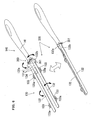
FIG. 2 is a perspective view showing thecleaning element holder 120 ofFIG. 1 in a holding plate unfolded state and in a holding plate folded state. -
FIG. 3 is a perspective view of thecleaning element 110 ofFIG. 1 which is shown separated into component elements. -
FIG. 4 is a schematic view showing thecleaning element 110 when holdingplates 132 are in the holding plate unfolded state and in the holding plate folded state. -
FIG. 5 is a perspective view showing acleaning element holder 220 in the holding plate unfolded state and in the holding plate folded state. -
FIG. 6 is a perspective view showing acleaning element holder 320 in the holding plate unfolded state and in the holding plate folded state. - Each of the additional features and method steps disclosed above and below may be utilized separately or in conjunction with other features and method steps to provide improved cleaning tools and methods for using such cleaning tools and devices utilized therein. Representative examples of the invention, which examples utilized many of these additional features and method steps in conjunction, will now be described in detail with reference to the drawings. This detailed description is merely intended to teach a person skilled in the art further details for practicing preferred aspects of the present teachings and is not intended to limit the scope of the invention. Only the claims define the scope of the claimed invention. Therefore, combinations of features and steps disclosed within the following detailed description may not be necessary to practice the invention in the broadest sense, and are instead taught merely to particularly describe some representative examples of the invention, which detailed description will now be given with reference to the accompanying drawings.
- A representative embodiment of the present invention is now described with reference to the drawings. First, the structure of a
cleaning tool 100 according to this embodiment is explained with reference toFIGS. 1 to 3 . Objects to be cleaned with thecleaning tool 100 includes regions to be cleaned (floors, walls, windows, ceilings, external walls, furniture, clothes, curtains, bedding, lighting, home electric appliances, etc.) inside and outside of houses, apartments, buildings, factories, vehicles, etc. and regions of human body parts to be cleaned. These regions to be cleaned may be either flat or curved, uneven or stepped. -
FIG. 1 shows thecleaning tool 100 according to this embodiment in perspective view, in a state disassembled into acleaning element 110 and acleaning element holder 120. As shown inFIG. 1 , thecleaning tool 100 comprises thecleaning element 110 and thecleaning element holder 120. - The
cleaning element 110 has a function of removing dirt on the region to be cleaned. Thecleaning element 110 is available in a sheet-like form, and in use, it is loosened such that its volume is increased. As shown inFIG. 1 , thecleaning element 110 is a sheet element having a rectangular shape in plan view and extending in a predetermined longitudinal direction (the direction of the length), which will be explained in more detail below. Thecleaning element 110 includes acleaning element body 111 and a holdingsheet 112 stacked and fusion bonded together at a fusion bondedpart 113 and fusion bondedparts 114 which are parallel to each other. A pair of right and left spaces demarcated by the fusion bondedparts form insert regions 115 into which holding portions (holdingplates 132 of aholder body 130 which is described below) of thecleaning element holder 120 are inserted. Theinsert regions 115 are configured to have adequate size (insertion width and insertion depth) to receive the holdingplates 132 of theholder body 130. Thecleaning element 110 is a feature that corresponds to the "cleaning element" according to this invention. Thecleaning element 110 may also have a square or other shape in plan view as necessary. Further, theinsert regions 115 are the features that correspond to the "insert region" according to this invention. Each of theinsert regions 115 may be formed by a single insert portion extending elongate or by a plurality of insert portions extending discontinuously. - The
cleaning element holder 120 is removably attached to thecleaning element 110. Thecleaning element holder 120 is an elongate member including theholder body 130 and thehandle 140 connected to each other. Thecleaning element holder 120 is a feature that corresponds to the "cleaning element holder" according to this invention. Thehandle 140 includes ahandle body 141 extending in an elongate form and a connection 141a disposed between thehandle body 141 and theholder body 130. Thehandle body 141 is a portion to be held by a user. Thehandle body 141 and theholder body 130 are fixedly connected at the connection 141a. Thehandle 140 and thehandle body 141 here form the "grip" according to this invention. - The
holder body 130 has a function of detachably holding thecleaning element 110. Theholder body 130 includes a pair of right and left holdingplates 132 and a retainingplate 134 which are formed on abase 131 of thehandle 140. The holdingplates 132 extend forward in the longitudinal direction from thebase 131 and parallel with a predetermined spacing therebetween on the same plane. In other words, theholder body 130 has a bifurcated form. Each of the holdingplates 132 has a constant width in the longitudinal direction or is tapered. The two holdingplates 132 here form the "two holding elements" and the "plate-like members" according to this invention. The holdingplates 132 can have an appropriately selected sectional shape such as a circular or polygonal section forming a rod-like shape. - Further, two
projections 133 are formed on the front and rear portions of the outer edge of each of the holdingplates 132. Each of theprojections 133 has an elliptic contour projecting outward from the holdingplate 132 and has a convexly curved projecting surface. Further, an opening orhollow portion 133a is formed in the central portion of theprojection 133. The retainingplate 134 extends forward between thepair holding plates 132 and is convexly curved downward. The retainingplate 134 further has an engagement lug (not shown) on the underside. - The holding
plates 132 can be inserted into the associatedinsert regions 115 and have a function of holding thecleaning element 110 in the inserted state. In the inserted state, the holdingplates 132 are fitted in the associatedinsert regions 115 by close sliding contact, so that thecleaning element 110 is securely attached to the holdingplate 132. Further, in the inserted state, the retainingplate 134 presses thecleaning element 110 from above, and the engagement lug (not shown) formed on the underside of the retainingplate 134 serves as a stopper for preventing thecleaning element 110 from coming off. Thus, in the inserted state in which the holdingplates 132 are inserted into theinsert regions 115 of thecleaning element 110, thecleaning element 110 is reliably retained by theholder body 130. - Further, in this embodiment, each of the holding
plates 132 has ahinge 131 a on the base 131 side and can rotate via thehinge 131a in the directions shown by the double-headed arrow inFIG. 1 , or toward and away from the other. Thehinges 131a are rotation axes provided between the holdingplates 132 and are the features that correspond to the "rotation axis" according to this invention.FIG. 2 refers to this rotation of the holdingplates 132.FIG. 2 is a perspective view showing thecleaning element holder 120 ofFIG. 1 in a holding plate unfolded state and in a holding plate folded state. As shown, thecleaning element holder 120 can be changed between the holding plate unfolded state in which the holdingplates 132 are unfolded, and the holding plate folded state in which the holdingplates 132 are folded toward each other via thehinges 131a. - In order to change the
cleaning element holder 120 from the holding plate unfolded state to the holding plate folded state, the user folds the holdingplates 132 inward via thehinges 131a. At this time, the holdingplates 132 are rotated such that the upper surfaces of the holdingplates 132 face each other. The upper surfaces of the holdingplates 132 are designed as a support surface (which is a feature that corresponds to the "support surface" according to this invention) for supporting thecleaning element 110 from below when the holdingplates 132 are inserted into theinsert regions 115. In this holding plate folded state, arotary lever 150 is used to lock the rotational position of the holdingplates 132. Therotary lever 150 is a ring-like member disposed in such a manner as to encircle the connection 141 a. Therotary lever 150 can be rotated forward and rearward (in the directions shown by the double-headed arrow inFIG. 1 ) on a predetermined pivot point (not shown) provided on the connection 141a. Further, therotary lever 150 can be locked in forward and rearward rotational positions by respective appropriate locking mechanisms. Therefore, when therotary lever 150 is rotated to the forward rotational position in the folded state of the holdingplates 132, therotary lever 150 is set in the forward rotational position in which therotary lever 150 encircles the rear end side of the holdingplates 132. As a result, the folded holdingplates 132 are pressed in a cramping manner from outside by the inner surface of therotary lever 150 and thus locked in the rotational position. - In order to change the
cleaning element holder 120 from the holding plate folded state to the holding plate unfolded state, first, the user turns therotary lever 150 from the forward rotational position to the rearward rotational position, so that the lock of the rotational position of the holdingplates 132 is released. Thereafter, the user unfolds the folded holdingplates 132 outward via thehinges 131a. - The
cleaning element holder 120 may have an appropriately selected structure, such as a structure in which theholder body 130 and the handle 140 (thehandle body 141 and the connection 141a) are separately formed and designed to be assembled together, a structure in which theholder body 130 and thehandle 140 are integrally formed, and a structure in which two of theholder body 130, thehandle 140 and the connection 141a are integrally formed. - Referring to
FIG. 3 , the structure of thecleaning element 110 is specifically described.FIG. 3 is a perspective view of a layered part 110a of thecleaning element 110 ofFIG. 1 which is shown separated into component elements. - As shown in FTG. 3, in the
cleaning element 110 of this embodiment, the holdingsheet 112 is overlaid on thecleaning element body 111 on the cleaning side (which is also referred to as the "lower region side" or the "back"). Further, thecleaning element body 111 has acleaning side sheet 111c, afiber assembly 111b and abase sheet 111a placed one on the other in this order from the cleaning side (lower region side). In this case, the holdingsheet 112 and thebase sheet 111a are overlaid on the side of thefiber assembly 111b opposite thecleaning side sheet 111c (lower region side sheet) and form an upper region side sheet. - The
base sheet 111a, thefiber assembly 111b and thecleaning side sheet 111c which form thecleaning element body 111 have the same rectangular sheet-like form in plan view and extend in a longitudinal direction of thecleaning element 110. Thefiber assembly 111b and thecleaning side sheet 111c form a brush-like part having a dirt removing function, which is also referred to as the "brush portion". Thecleaning element 110 may be of a disposable type designed for single use, a disposable type designed for multiple use which can be used several times, while holding dust which has been removed from the region to be cleaned on the brush portion, or a reusable type which can be reused by washing. Further, in this embodiment, thecleaning element body 111 of thecleaning element 110 is described as a structure having thebase sheet 111a, thefiber assembly 111b and thecleaning side sheet 111c stacked in layer, but may be constructed as a structure having an additional fiber layer and/or sheet. - The holding
sheet 112, thebase sheet 111a and thecleaning side sheet 111c have a plurality of zigzag strips (strip portions) extending in a direction perpendicular to (ie crossing) the longitudinal direction of thecleaning element 110. Specifically, the holdingsheet 112 comprises a plurality ofstrips 112a arranged in parallel and extending in a direction crossing the longitudinal direction of thecleaning element 110. Thebase sheet 111a comprises a plurality ofstrips 111d arranged in parallel and extending in a direction crossing the longitudinal direction of thecleaning element 110. Thecleaning side sheet 111c comprises a plurality ofstrips 111e arranged in parallel and extending in a direction crossing the longitudinal direction of thecleaning element 110. An improved structure which can easily trap dust and thus has a higher cleaning function can be realized by the zigzag strips of the sheets. The strips may have the same kind or different kinds of shape appropriately selected from various shapes, such as zigzag, linear and curved shapes. - The construction of the nonwoven fabric forming the above-described
base sheet 111a, cleaningside sheet 111c and holdingsheet 112 and the construction of thefiber assembly 111b are now explained in detail. - The
base sheet 111a, thecleaning side sheet 111c and the holdingsheet 112 can typically be formed of sheet-type nonwoven fabric comprising thermal melting fibers (thermoplastic fibers) and thus referred to as nonwoven fabric sheet. Thebase sheet 111a and the holdingsheet 112 herein form the "sheet-type nonwoven fabric" according to this invention. The nonwoven fabric has a sheet-like configuration formed by fixing or entangling fibers by mechanical, chemical or heat treatment. The nonwoven fabric partly includes thermoplastic fibers and thus can be fusion bonded. Further, the nonwoven fabric has a plurality of strips. Examples of the thermal melting fibers (thermoplastic fibers) include polyethylene, polypropylene and polyethylene terephthalate. The nonwoven fabric may be manufactured by through-air bonding, spun bonding, thermal bonding, spun lacing, point bonding, melt blowing, stitch bonding, chemical bonding, needle punching or other similar processes. This nonwoven fabric is a feature that corresponds to the "nonwoven fabric" according to this invention. In order to enhance the dust wiping function, it is preferred to use a nonwoven fabric having higher rigidity. Further, as an alternative to or in addition to the nonwoven fabric, a material to be worked into strips, such as urethane, sponge, woven fabric, net and split cloth, may be used. - The
fiber assembly 111b is a single fiber structure formed by fibers, a fiber structure having fibers aligned in the length direction and/or the radial direction (twist yarn, spun yarn, yarn to which a plurality of filaments are partially connected), or an assembly of the fiber structures. Thefiber assembly 111b partially includes thermoplastic fibers and can be fusion bonded. The fibers forming thefiber assembly 111b are elements of yarn, textile or the like and defined as being thin and flexible fibers having a substantially longer length compared with the thickness. Typically, a long continuous fiber is defined as a filament and a short fiber as a staple. The proximal ends of the fibers of thefiber assembly 111b are bonded at the fusion bondedparts fiber assembly 111b each have one end fixed at the fusion bonded parts and the other free end (distal end) on the opposite side. The fibers of thefiber assembly 111b extend in a direction crossing the longitudinal direction of the cleaning element 110 (or thefiber assembly 111b). Thefiber assembly 111b extending in a direction crossing the longitudinal direction of thecleaning element 110 is a feature that corresponds to the "fiber assembly comprising a plurality of fibers extending in the predetermined direction" according to this embodiment. Thefiber assembly 111b is also referred to as the "fiber bundle" having a plurality of fibers in a bundle. - In the representative example shown in
FIG. 3 , thefiber assembly 111b comprises three fiber layers, but it may comprise one or more fiber layers as necessary. Preferably, thefiber assembly 111b has a planar structure having a predetermined flat or curved region and has a three-dimensional form having a certain thickness or has a thin sheet-like form. The "fiber assembly" is typically formed of polyethylene (PE), polypropylene (PP), polyethylene terephthalate (PET), nylon, rayon or the like. In practical use, an assembly of filaments formed by opening a tow is frequently used as the fiber assembly. It is particularly preferable that the fiber assembly comprises conjugated fibers having a core of polypropylene (PP) or polyethylene (PE) and a core covering sheath of polyethylene (PE). Further, the filaments of the fiber assembly are preferred to have a fineness of 1 to 50 dtex, more preferably 2 to 10 dtex. The individual fiber assembly may contain fibers of substantially the same fineness or of different finenesses. - Further, in order to enhance the dust wiping function, it is preferred to use a fiber assembly including fibers having higher rigidity or fibers having higher fineness. It is further preferred that the fiber assembly has crimped fibers. Here, the crimped fibers are fibers subjected to a predetermined crimping process and easily entangled with each other. With the fibers being crimped, the fiber assembly becomes bulkier than before the holder is attached thereto, and dust can be easily captured by the crimped portions. This structure can be realized especially by using crimped fibers opened from a tow.
- For the fiber assembly, flat yarns or split yarns may also be employed. The flat yarns are prepared by slitting a film into tapes and by stretching the tapes in the longitudinal direction. The split yarns are prepared by splitting a thermoplastic film resin in the direction perpendicular to the orientation direction of the resin so that the film is fibrillated and interconnected into a net shape. Alternatively, a nonwoven fabric which is bulky and has low fiber density, such as a through-air bonded nonwoven fabric, may be employed to form the fiber assembly.
- The kinds and numbers of the component parts of the
cleaning element 110 are not limited to those described in the above-described example, and can be selected as necessary. - Operation of the
cleaning tool 100 having the above-described construction is described with reference toFIGS. 2 and4. FIG. 4 schematically shows thecleaning element 110 in the holding plate unfolded state and in the holding plate folded state of the holdingplates 132 in this embodiment. - In using the
cleaning tool 100 to wipe a region to be cleaned, in order to attach thecleaning element 110 and thecleaning element holder 120 to each other, first, thecleaning element holder 120 is set in the holding plate unfolded state as shown inFIG. 2 . Then, the holdingplates 132 of theholder body 130 are inserted into theinsert regions 115 of thecleaning element 110. Thus, thecleaning element 110 and thecleaning element holder 120 are attached to each other. At this time, preferably, in order to enhance the cleaning effect, thecleaning element 110 is fluffed as necessary so that the volume of thecleaning element 110 is increased. In the holding plate unfolded state of thecleaning element holder 120, thecleaning element 110 is set in first cleaning mode as shown inFIG. 4 . In the first cleaning mode, the lower surface of the cleaning element forms the cleaning face of thecleaning element 110 to be used for wiping. - Further, by rotating the holding
plates 132 inserted into theinsert regions 115 and therotary lever 150, thecleaning element holder 120 can be changed from the holding plate unfolded state to the holding plate folded state. At this time, the holdingplates 132 inserted into theinsert regions 115 can be rotated in parallel toward each other around the longitudinal axis of theholder body 130 on thehinges 131a disposed between the holdingplates 132 such that the holdingsheet 112 is positioned on the internal side of the cleaning element. Through this rotation, the sectional shape of thecleaning element 110 can be changed in the direction crossing the longitudinal direction of theholder body 130; as shown, the cross-sectional shape of the cleaning element is changeable in the direction perpendicular to the longitudinal direction of the holder body. Further, in order to realize the "parallel" state of the holdingplates 132 here, it is only necessary to create the state in which the two holdingplates 132 are arranged in parallel to each other. Thus, the parallel state widely embraces the state in which the holdingplates 132 extend substantially in the same direction, and the state in which the holdingplates 132 extend parallel to each other at least either before or after rotation. Further, the rotation axis of the holdingplates 132 may be configured as separate rotation axes like thehinges 131a which are separately provided on therespective holding plates 132, or as a single rotation axis common to the two holdingplates 132. - In the holding plate folded state of the
cleaning element holder 120, thecleaning element 110 is set in second cleaning mode as shown inFIG. 4 . In the second cleaning mode, thecleaning element 110 surrounds the holdingplates 132 such that thefiber assembly 111b side of thecleaning element 110 forms the external surface of the cleaning element. Thus, thecleaning element 110 entirely surrounds the holdingplates 132, so that the cleaning face of thecleaning element 110 to be used for wiping is formed substantially by the entire external surface of thecleaning element 110. As a result, the volume of the sheet-type cleaning element 110 can be increased, and dust can be trapped on the entire face of the cleaning element. Further, the user can use the cleaning tool without being concerned about the position of the cleaning face of the cleaning element during cleaning operation. Therefore, the cleaning effect can be enhanced. - The present invention is not limited to the embodiment as described above, but rather, may be added to, changed, replaced with alternatives or otherwise modified. For example, the following provisions can be made in application of this embodiment.
- In this invention, the holding
plates 132 of thecleaning element holder 120 are set in the holding plate unfolded state and the holding plate folded state as shown inFIG. 4 . Cleaning element holders having a construction which is different from that of thecleaning element holder 120 in the above-described embodiment can be appropriately used instead. Other embodiments of the "cleaning element holder" according to this invention are now described with reference toFIGS, 5 and6 . In FTGS. 5 and 6, parts identical to those in the above embodiment shown inFIG. 2 are given like numerals as in the first embodiment and will not be described. -
FIG. 5 is a perspective view showing acleaning element holder 220 of a different embodiment in a holding plate unfolded state and in a holding plate folded state. Thecleaning element holder 220 substantially has the same construction as thecleaning element holder 120 except for aslide button 250 which is used in place of therotary lever 150. Theslide button 250 is a cylindrical member disposed in such a manner as to encircle the connection 141a. Theslide button 250 can be slid forward and rearward (in the directions shown by the double-headed arrow inFIG. 1 ). Further, theslide button 250 can be locked in forward and rearward slide positions by respective appropriate locking mechanisms. - When the
slide button 250 is slid to the forward slide position in the folded state of the holdingplates 132, theslide button 250 is set in the forward slide position in which theslide button 250 encircles the rear end side of the holdingplates 132. As a result, the folded holdingplates 132 are pressed in a cramping manner from outside by the inner surface of theslide button 250 and thus locked in the slide position. In order to change thecleaning element holder 220 from the holding plate folded state to the holding plate unfolded state, first, the user moves theslide button 250 from the forward slide position to the rearward slide position, so that the lock of the rotational position of the holdingplates 132 is released. Thereafter, the user unfolds the folded holdingplates 132 outward via thehinges 131a. Like thecleaning element holder 120, thecleaning element holder 220 having such a construction can also be changed between the holding plate folded state and the holding plate unfolded state, so that thecleaning element 110 can be set in the first and second cleaning modes as shown inFIG. 4 . Thus, the cleaning effect can also be enhanced. - FTG. 6 is a perspective view showing a
cleaning element holder 320 of a different embodiment in a holding plate unfolded state and in a holding plate folded state. Thecleaning element holder 320 substantially has the same construction as thecleaning element holders gear mechanism 350 which is used in place of therotary lever 150 or theslide button 250. Thegear mechanism 350 includes a pair of right and left rotary gears 351, 352 having gear teeth on the outer periphery and rotatably disposed in engagement with each other. Therotary gear 351 is engaged with a gear groove (not shown) formed in one of the holdingplates 132, and the rotary gear 352 is engaged with a gear groove (not shown) formed in the other holdingplate 132. - When a
lug 132a of the oneholding plate 132 or alug 132b of the other holdingplate 132 is rotated inward, the holdingplates 132 are folded toward each other via thehinges 131a and set in the holding plate folded state, while being kept in engagement with the rotary gears 351, 352 at thelugs plates 132 are locked in the rotational position by the resistance of gear engagement of the rotary gears 351, 352 and an appropriate lock mechanism for locking thelugs lug cleaning holder 320 outward in the holding plate folded state, the holdingplates 132 are unfolded away from each other via thehinges 131a and set in the holding plate unfolded state, while being kept in engagement with the rotary gears 351, 352 at thelugs cleaning element holders cleaning element holder 320 having such a construction can also be changed between the holding plate folded state and the holding plate unfolded state, so that thecleaning element 110 can be set in the first and second cleaning modes as shown inFIG. 4 . Thus, the cleaning effect can also be enhanced. - In the above embodiments, the
cleaning element 110 is described as being formed by the sheet-type nonwoven fabric and the fiber assembly. According to the invention, however, the cleaning element may alternatively be formed only by sheet-type nonwoven fabric. - Further, in the above-embodiments, both of the holding
plates 132 can be moved with respect to the grip in the form of thehandle body 141, either together or independently. According to the invention, however, it may also be constructed such that either one of the holdingplates 132 can be moved with respect to thehandle body 141, with the other holding plate being non-moveable.
Whilst the present invention is described as having two holding elements (the holding plates), more may be provided, so long as two of them are rotatable in parallel towards each other. -
- 100
- cleaning tool
- 110
- cleaning element
- 110a
- layered part
- 111
- cleaning element body
- 111a
- base sheet
- 111b
- fiber assembly
- 111c
- cleaning side sheet
- 111d,
- 111e strip
- 112
- holding sheet
- 112a
- strip
- 113, 114
- fusion bonded part
- 115
- insert region
- 120, 220, 320
- cleaning element holder
- 130
- holder body
- 131
- base
- 131
- a hinge
- 132
- holding plate
- 132a, 132b
- lug
- 133
- projection
- 133
- hollow portion
- 134
- retaining plate
- 140
- handle
- 141
- handle body
- 141a
- connection
- 150
- rotary lever
- 250
- slide button
- 350
- gear mechanism
- 351
- rotary gear
Claims (7)
- A cleaning tool (100) for wiping a region to be cleaned, comprising:an elongate cleaning element holder (120), anda cleaning element (110) to be attached to the cleaning element holder, wherein:the cleaning element holder has a grip (130, 141) to be held by a user and two holding elements (132) extending parallel in a longitudinal direction from the grip, the holding elements being adapted to be inserted into an insert region (115) of the cleaning element to thereby hold the cleaning element,characterized in that the two holding elements of the cleaning element holder are rotatable in parallel towards each other around a longitudinal axis of the cleaning element holder on a rotation axis (131 a) disposed between the holding elements, whereby, through the rotation of the two holding elements inserted into the insert region, the sectional shape of the cleaning element is changeable in a direction crossing the longitudinal direction of the cleaning element holder.
- A cleaning tool as claimed in claim 1, wherein the two holding elements comprise plate-like members extending parallel to each other on the same plane, each of the plate-like members having a support surface for supporting the cleaning element when the plate-like member is inserted into the insert region, and the plate-like member being rotatable on the rotation axis such that the support surfaces of the plate-like members face each other.
- A cleaning tool as claimed in claim 1 or 2, wherein:the cleaning element (110) includes a fiber assembly (111 b) having a plurality of fibers extending in a predetermined direction, and a base sheet (111a) and a holding sheet (112) which are both formed of sheet-type nonwoven fabric, the base sheet and the holding sheet being stacked in layer and bonded together to thereby form the insert region (115), and the fiber assembly being further overlaid on the side of the base sheet opposite the holding sheet, and whereinthe holding elements (132) of the cleaning element holder which are inserted into the insert region are rotatable towards each other such that the holding sheet is positioned on the internal side of the cleaning element, whereby the cleaning element surrounds the holding element such that the fiber assembly side of the cleaning element forms the external surface of the cleaning element.
- . A cleaning tool as claimed in any preceding claim, wherein means (131a) are provided to permit rotation of the holding elements around a longitudinal axis of the cleaning element holder.
- . A cleaning tool as claimed in any preceding claim, wherein the unattached cleaning element is substantially planar and the insert region is shaped to allow the holding elements, once inserted, to lie in the plane of the cleaning element.
- . A cleaning tool as claimed in any preceding claim, wherein means are provided to lock the holding elements in their rotational position.
- . A cleaning tool as claimed in any preceding claim, wherein the cleaning element holder has only two holding elements.
Applications Claiming Priority (1)
| Application Number | Priority Date | Filing Date | Title |
|---|---|---|---|
| JP2007054929A JP4934464B2 (en) | 2007-03-05 | 2007-03-05 | Cleaning tool |
Publications (3)
| Publication Number | Publication Date |
|---|---|
| EP1967119A2 true EP1967119A2 (en) | 2008-09-10 |
| EP1967119A3 EP1967119A3 (en) | 2011-12-07 |
| EP1967119B1 EP1967119B1 (en) | 2013-04-17 |
Family
ID=39387228
Family Applications (1)
| Application Number | Title | Priority Date | Filing Date |
|---|---|---|---|
| EP08152334.2A Not-in-force EP1967119B1 (en) | 2007-03-05 | 2008-03-05 | Cleaning tool |
Country Status (7)
| Country | Link |
|---|---|
| US (1) | US8156603B2 (en) |
| EP (1) | EP1967119B1 (en) |
| JP (1) | JP4934464B2 (en) |
| KR (1) | KR101447624B1 (en) |
| CN (1) | CN101259003B (en) |
| CA (1) | CA2623046A1 (en) |
| MX (1) | MX2008003124A (en) |
Cited By (2)
| Publication number | Priority date | Publication date | Assignee | Title |
|---|---|---|---|---|
| EP2954825A4 (en) * | 2013-02-07 | 2016-09-07 | Unicharm Corp | CLEANING TOOL |
| EP3269285A4 (en) * | 2015-03-12 | 2018-05-30 | Uni-Charm Corporation | Cleaning sheet and cleaning instrument |
Families Citing this family (24)
| Publication number | Priority date | Publication date | Assignee | Title |
|---|---|---|---|---|
| JP5271787B2 (en) * | 2009-04-22 | 2013-08-21 | 株式会社ニトムズ | Cleaning device |
| JP5436042B2 (en) * | 2009-05-21 | 2014-03-05 | ユニ・チャーム株式会社 | Cleaning body holder, cleaning tool |
| USD685151S1 (en) * | 2010-04-06 | 2013-06-25 | The Procter & Gamble Company | Handle for holding a cleaning device |
| USD674979S1 (en) * | 2010-08-11 | 2013-01-22 | The Procter & Gamble Company | Telescoping handle |
| CN103371779B (en) * | 2012-04-23 | 2015-12-16 | 杨雅菁 | Dust removal handle that can be automatically folded in half to become longer or shorter |
| US9386899B2 (en) * | 2013-01-23 | 2016-07-12 | Ya-Ching Yang | Foldable duster |
| JP5484622B1 (en) * | 2013-02-07 | 2014-05-07 | ユニ・チャーム株式会社 | Cleaning tool |
| JP6239827B2 (en) * | 2013-02-07 | 2017-11-29 | ユニ・チャーム株式会社 | Cleaning tool |
| USD720903S1 (en) * | 2013-08-08 | 2015-01-06 | Ez Products Of South Florida, L.L.C. | Duster handle |
| CA3076704C (en) * | 2015-01-16 | 2022-03-15 | Ecolab Usa Inc. | Tool assembly comprising universal handle and interchangeable tool heads |
| USD782765S1 (en) * | 2015-03-04 | 2017-03-28 | Nice-Pak Products, Inc. | Cleaning device |
| USD905366S1 (en) * | 2018-01-05 | 2020-12-15 | The Procter & Gamble Company | Handle for holding a cleaning device |
| PL3530171T3 (en) | 2018-02-23 | 2021-10-18 | Eurofilters Holding N.V. | Holding plate with sealing element |
| CN109487350A (en) * | 2018-10-19 | 2019-03-19 | 山东超亚刷丝有限公司 | A method of plastotype manufacture screw thread brush filament is squeezed by heating to monofilament |
| JP7213794B2 (en) * | 2019-03-08 | 2023-01-27 | ユニ・チャーム株式会社 | cleaning sheet |
| WO2020183923A1 (en) * | 2019-03-08 | 2020-09-17 | ユニ・チャーム株式会社 | Cleaning sheet |
| JP7275021B2 (en) * | 2019-03-08 | 2023-05-17 | ユニ・チャーム株式会社 | cleaning sheet |
| WO2020183922A1 (en) * | 2019-03-08 | 2020-09-17 | ユニ・チャーム株式会社 | Cleaning sheet |
| KR102123527B1 (en) | 2019-04-04 | 2020-06-17 | (주)광진상사 | Cleaning tool |
| KR102148684B1 (en) | 2019-04-04 | 2020-08-27 | 황성철 | Cleaning tool |
| PL3838095T3 (en) * | 2019-12-20 | 2023-01-09 | Eurofilters Holding N.V. | Holding plate for a vacuum cleaner filter bag |
| USD1046353S1 (en) * | 2022-03-22 | 2024-10-08 | Michael Clare | Golf glove drying device |
| USD1063271S1 (en) * | 2023-05-15 | 2025-02-18 | Kangduole Co., Ltd. | Handle for a cleaning article |
| USD1089919S1 (en) * | 2023-11-07 | 2025-08-19 | Daniel Noriega | Flexible duster handle |
Citations (1)
| Publication number | Priority date | Publication date | Assignee | Title |
|---|---|---|---|---|
| JPH09154791A (en) | 1995-12-08 | 1997-06-17 | Kao Corp | Cleaning cloth and cleaning tool |
Family Cites Families (10)
| Publication number | Priority date | Publication date | Assignee | Title |
|---|---|---|---|---|
| DK134992D0 (en) * | 1992-11-05 | 1992-11-05 | Dit International Hq A S | HOLDER |
| CN1184922C (en) * | 2000-07-10 | 2005-01-19 | 尤妮佳股份有限公司 | Cleaning article |
| IL152340A (en) * | 2001-02-23 | 2007-12-03 | Yoshinori Tanaka | Cleaning article |
| JP2005161051A (en) * | 2003-12-03 | 2005-06-23 | Oimo Industrial Co Ltd | Hand mop |
| US6978509B2 (en) * | 2004-02-06 | 2005-12-27 | Pai Yung Lin | Cleansing device having cleansing fibers |
| JP4785369B2 (en) | 2004-11-16 | 2011-10-05 | ユニ・チャーム株式会社 | Cleaning goods |
| TWM272500U (en) * | 2004-12-22 | 2005-08-11 | Rock Tone Entpr Co Ltd | Dust removal whisk structure |
| JP3683266B1 (en) * | 2005-03-14 | 2005-08-17 | ユニ・チャーム株式会社 | Cleaning goods |
| US20060260082A1 (en) * | 2005-05-20 | 2006-11-23 | The Procter & Gamble Company | Cleaning implement |
| TW200706146A (en) * | 2005-08-12 | 2007-02-16 | Ya-Jing Yang | Duster |
-
2007
- 2007-03-05 JP JP2007054929A patent/JP4934464B2/en not_active Expired - Fee Related
-
2008
- 2008-02-29 CA CA002623046A patent/CA2623046A1/en not_active Abandoned
- 2008-03-04 KR KR1020080020097A patent/KR101447624B1/en not_active Expired - Fee Related
- 2008-03-05 US US12/042,469 patent/US8156603B2/en not_active Expired - Fee Related
- 2008-03-05 EP EP08152334.2A patent/EP1967119B1/en not_active Not-in-force
- 2008-03-05 MX MX2008003124A patent/MX2008003124A/en active IP Right Grant
- 2008-03-05 CN CN2008100827593A patent/CN101259003B/en not_active Expired - Fee Related
Patent Citations (1)
| Publication number | Priority date | Publication date | Assignee | Title |
|---|---|---|---|---|
| JPH09154791A (en) | 1995-12-08 | 1997-06-17 | Kao Corp | Cleaning cloth and cleaning tool |
Cited By (3)
| Publication number | Priority date | Publication date | Assignee | Title |
|---|---|---|---|---|
| EP2954825A4 (en) * | 2013-02-07 | 2016-09-07 | Unicharm Corp | CLEANING TOOL |
| US10383503B2 (en) | 2013-02-07 | 2019-08-20 | Unicharm Corporation | Cleaning tool |
| EP3269285A4 (en) * | 2015-03-12 | 2018-05-30 | Uni-Charm Corporation | Cleaning sheet and cleaning instrument |
Also Published As
| Publication number | Publication date |
|---|---|
| KR20080081836A (en) | 2008-09-10 |
| JP2008212431A (en) | 2008-09-18 |
| CN101259003B (en) | 2013-06-05 |
| KR101447624B1 (en) | 2014-10-06 |
| CN101259003A (en) | 2008-09-10 |
| MX2008003124A (en) | 2009-02-25 |
| CA2623046A1 (en) | 2008-09-05 |
| US20080216261A1 (en) | 2008-09-11 |
| EP1967119A3 (en) | 2011-12-07 |
| JP4934464B2 (en) | 2012-05-16 |
| EP1967119B1 (en) | 2013-04-17 |
| US8156603B2 (en) | 2012-04-17 |
Similar Documents
| Publication | Publication Date | Title |
|---|---|---|
| EP1967119B1 (en) | Cleaning tool | |
| EP2255713B1 (en) | Cleaning element and cleaning tool | |
| EP1974646B1 (en) | Cleaning element and cleaning tool | |
| EP2080470B1 (en) | Cleaning body and cleaning tool | |
| EP1974648B1 (en) | Cleaning element and cleaning tool | |
| EP1982627B1 (en) | Cleaning body and cleaning tool | |
| EP1967118B1 (en) | Cleaning tool | |
| EP1967120B1 (en) | Cleaning tool and cleaning element | |
| EP2277428A1 (en) | Cleaner | |
| EP1967117B1 (en) | Cleaning tool and cleaning element |
Legal Events
| Date | Code | Title | Description |
|---|---|---|---|
| PUAI | Public reference made under article 153(3) epc to a published international application that has entered the european phase |
Free format text: ORIGINAL CODE: 0009012 |
|
| AK | Designated contracting states |
Kind code of ref document: A2 Designated state(s): AT BE BG CH CY CZ DE DK EE ES FI FR GB GR HR HU IE IS IT LI LT LU LV MC MT NL NO PL PT RO SE SI SK TR |
|
| AX | Request for extension of the european patent |
Extension state: AL BA MK RS |
|
| PUAL | Search report despatched |
Free format text: ORIGINAL CODE: 0009013 |
|
| AK | Designated contracting states |
Kind code of ref document: A3 Designated state(s): AT BE BG CH CY CZ DE DK EE ES FI FR GB GR HR HU IE IS IT LI LT LU LV MC MT NL NO PL PT RO SE SI SK TR |
|
| AX | Request for extension of the european patent |
Extension state: AL BA MK RS |
|
| RIC1 | Information provided on ipc code assigned before grant |
Ipc: A47L 13/46 20060101ALI20111031BHEP Ipc: A47L 13/38 20060101AFI20111031BHEP Ipc: B25G 3/24 20060101ALI20111031BHEP |
|
| 17P | Request for examination filed |
Effective date: 20120530 |
|
| AKX | Designation fees paid |
Designated state(s): AT BE BG CH CY CZ DE DK EE ES FI FR GB GR HR HU IE IS IT LI LT LU LV MC MT NL NO PL PT RO SE SI SK TR |
|
| RIC1 | Information provided on ipc code assigned before grant |
Ipc: A47L 13/38 20060101AFI20120801BHEP Ipc: A47L 13/46 20060101ALI20120801BHEP Ipc: B25G 3/24 20060101ALI20120801BHEP |
|
| GRAP | Despatch of communication of intention to grant a patent |
Free format text: ORIGINAL CODE: EPIDOSNIGR1 |
|
| GRAS | Grant fee paid |
Free format text: ORIGINAL CODE: EPIDOSNIGR3 |
|
| GRAA | (expected) grant |
Free format text: ORIGINAL CODE: 0009210 |
|
| AK | Designated contracting states |
Kind code of ref document: B1 Designated state(s): AT BE BG CH CY CZ DE DK EE ES FI FR GB GR HR HU IE IS IT LI LT LU LV MC MT NL NO PL PT RO SE SI SK TR |
|
| REG | Reference to a national code |
Ref country code: GB Ref legal event code: FG4D |
|
| REG | Reference to a national code |
Ref country code: CH Ref legal event code: EP |
|
| REG | Reference to a national code |
Ref country code: IE Ref legal event code: FG4D |
|
| REG | Reference to a national code |
Ref country code: AT Ref legal event code: REF Ref document number: 606731 Country of ref document: AT Kind code of ref document: T Effective date: 20130515 |
|
| REG | Reference to a national code |
Ref country code: DE Ref legal event code: R096 Ref document number: 602008023838 Country of ref document: DE Effective date: 20130613 |
|
| REG | Reference to a national code |
Ref country code: AT Ref legal event code: MK05 Ref document number: 606731 Country of ref document: AT Kind code of ref document: T Effective date: 20130417 |
|
| REG | Reference to a national code |
Ref country code: LT Ref legal event code: MG4D |
|
| REG | Reference to a national code |
Ref country code: NL Ref legal event code: VDEP Effective date: 20130417 |
|
| PG25 | Lapsed in a contracting state [announced via postgrant information from national office to epo] |
Ref country code: GR Free format text: LAPSE BECAUSE OF FAILURE TO SUBMIT A TRANSLATION OF THE DESCRIPTION OR TO PAY THE FEE WITHIN THE PRESCRIBED TIME-LIMIT Effective date: 20130718 Ref country code: IS Free format text: LAPSE BECAUSE OF FAILURE TO SUBMIT A TRANSLATION OF THE DESCRIPTION OR TO PAY THE FEE WITHIN THE PRESCRIBED TIME-LIMIT Effective date: 20130817 Ref country code: SE Free format text: LAPSE BECAUSE OF FAILURE TO SUBMIT A TRANSLATION OF THE DESCRIPTION OR TO PAY THE FEE WITHIN THE PRESCRIBED TIME-LIMIT Effective date: 20130417 Ref country code: ES Free format text: LAPSE BECAUSE OF FAILURE TO SUBMIT A TRANSLATION OF THE DESCRIPTION OR TO PAY THE FEE WITHIN THE PRESCRIBED TIME-LIMIT Effective date: 20130728 Ref country code: AT Free format text: LAPSE BECAUSE OF FAILURE TO SUBMIT A TRANSLATION OF THE DESCRIPTION OR TO PAY THE FEE WITHIN THE PRESCRIBED TIME-LIMIT Effective date: 20130417 Ref country code: BE Free format text: LAPSE BECAUSE OF FAILURE TO SUBMIT A TRANSLATION OF THE DESCRIPTION OR TO PAY THE FEE WITHIN THE PRESCRIBED TIME-LIMIT Effective date: 20130417 Ref country code: PT Free format text: LAPSE BECAUSE OF FAILURE TO SUBMIT A TRANSLATION OF THE DESCRIPTION OR TO PAY THE FEE WITHIN THE PRESCRIBED TIME-LIMIT Effective date: 20130819 Ref country code: FI Free format text: LAPSE BECAUSE OF FAILURE TO SUBMIT A TRANSLATION OF THE DESCRIPTION OR TO PAY THE FEE WITHIN THE PRESCRIBED TIME-LIMIT Effective date: 20130417 Ref country code: NO Free format text: LAPSE BECAUSE OF FAILURE TO SUBMIT A TRANSLATION OF THE DESCRIPTION OR TO PAY THE FEE WITHIN THE PRESCRIBED TIME-LIMIT Effective date: 20130717 Ref country code: LT Free format text: LAPSE BECAUSE OF FAILURE TO SUBMIT A TRANSLATION OF THE DESCRIPTION OR TO PAY THE FEE WITHIN THE PRESCRIBED TIME-LIMIT Effective date: 20130417 Ref country code: SI Free format text: LAPSE BECAUSE OF FAILURE TO SUBMIT A TRANSLATION OF THE DESCRIPTION OR TO PAY THE FEE WITHIN THE PRESCRIBED TIME-LIMIT Effective date: 20130417 |
|
| PG25 | Lapsed in a contracting state [announced via postgrant information from national office to epo] |
Ref country code: CY Free format text: LAPSE BECAUSE OF FAILURE TO SUBMIT A TRANSLATION OF THE DESCRIPTION OR TO PAY THE FEE WITHIN THE PRESCRIBED TIME-LIMIT Effective date: 20130417 Ref country code: PL Free format text: LAPSE BECAUSE OF FAILURE TO SUBMIT A TRANSLATION OF THE DESCRIPTION OR TO PAY THE FEE WITHIN THE PRESCRIBED TIME-LIMIT Effective date: 20130417 Ref country code: BG Free format text: LAPSE BECAUSE OF FAILURE TO SUBMIT A TRANSLATION OF THE DESCRIPTION OR TO PAY THE FEE WITHIN THE PRESCRIBED TIME-LIMIT Effective date: 20130717 Ref country code: HR Free format text: LAPSE BECAUSE OF FAILURE TO SUBMIT A TRANSLATION OF THE DESCRIPTION OR TO PAY THE FEE WITHIN THE PRESCRIBED TIME-LIMIT Effective date: 20130417 Ref country code: LV Free format text: LAPSE BECAUSE OF FAILURE TO SUBMIT A TRANSLATION OF THE DESCRIPTION OR TO PAY THE FEE WITHIN THE PRESCRIBED TIME-LIMIT Effective date: 20130417 |
|
| PG25 | Lapsed in a contracting state [announced via postgrant information from national office to epo] |
Ref country code: CZ Free format text: LAPSE BECAUSE OF FAILURE TO SUBMIT A TRANSLATION OF THE DESCRIPTION OR TO PAY THE FEE WITHIN THE PRESCRIBED TIME-LIMIT Effective date: 20130417 Ref country code: SK Free format text: LAPSE BECAUSE OF FAILURE TO SUBMIT A TRANSLATION OF THE DESCRIPTION OR TO PAY THE FEE WITHIN THE PRESCRIBED TIME-LIMIT Effective date: 20130417 Ref country code: DK Free format text: LAPSE BECAUSE OF FAILURE TO SUBMIT A TRANSLATION OF THE DESCRIPTION OR TO PAY THE FEE WITHIN THE PRESCRIBED TIME-LIMIT Effective date: 20130417 Ref country code: EE Free format text: LAPSE BECAUSE OF FAILURE TO SUBMIT A TRANSLATION OF THE DESCRIPTION OR TO PAY THE FEE WITHIN THE PRESCRIBED TIME-LIMIT Effective date: 20130417 |
|
| PLBE | No opposition filed within time limit |
Free format text: ORIGINAL CODE: 0009261 |
|
| STAA | Information on the status of an ep patent application or granted ep patent |
Free format text: STATUS: NO OPPOSITION FILED WITHIN TIME LIMIT |
|
| PG25 | Lapsed in a contracting state [announced via postgrant information from national office to epo] |
Ref country code: NL Free format text: LAPSE BECAUSE OF FAILURE TO SUBMIT A TRANSLATION OF THE DESCRIPTION OR TO PAY THE FEE WITHIN THE PRESCRIBED TIME-LIMIT Effective date: 20130417 Ref country code: RO Free format text: LAPSE BECAUSE OF FAILURE TO SUBMIT A TRANSLATION OF THE DESCRIPTION OR TO PAY THE FEE WITHIN THE PRESCRIBED TIME-LIMIT Effective date: 20130417 Ref country code: IT Free format text: LAPSE BECAUSE OF FAILURE TO SUBMIT A TRANSLATION OF THE DESCRIPTION OR TO PAY THE FEE WITHIN THE PRESCRIBED TIME-LIMIT Effective date: 20130417 |
|
| 26N | No opposition filed |
Effective date: 20140120 |
|
| REG | Reference to a national code |
Ref country code: DE Ref legal event code: R097 Ref document number: 602008023838 Country of ref document: DE Effective date: 20140120 |
|
| PGFP | Annual fee paid to national office [announced via postgrant information from national office to epo] |
Ref country code: GB Payment date: 20140226 Year of fee payment: 7 |
|
| PGFP | Annual fee paid to national office [announced via postgrant information from national office to epo] |
Ref country code: FR Payment date: 20140328 Year of fee payment: 7 Ref country code: DE Payment date: 20140520 Year of fee payment: 7 |
|
| PG25 | Lapsed in a contracting state [announced via postgrant information from national office to epo] |
Ref country code: LU Free format text: LAPSE BECAUSE OF FAILURE TO SUBMIT A TRANSLATION OF THE DESCRIPTION OR TO PAY THE FEE WITHIN THE PRESCRIBED TIME-LIMIT Effective date: 20140305 |
|
| REG | Reference to a national code |
Ref country code: CH Ref legal event code: PL |
|
| REG | Reference to a national code |
Ref country code: IE Ref legal event code: MM4A |
|
| PG25 | Lapsed in a contracting state [announced via postgrant information from national office to epo] |
Ref country code: CH Free format text: LAPSE BECAUSE OF NON-PAYMENT OF DUE FEES Effective date: 20140331 Ref country code: IE Free format text: LAPSE BECAUSE OF NON-PAYMENT OF DUE FEES Effective date: 20140305 Ref country code: LI Free format text: LAPSE BECAUSE OF NON-PAYMENT OF DUE FEES Effective date: 20140331 |
|
| REG | Reference to a national code |
Ref country code: DE Ref legal event code: R119 Ref document number: 602008023838 Country of ref document: DE |
|
| GBPC | Gb: european patent ceased through non-payment of renewal fee |
Effective date: 20150305 |
|
| REG | Reference to a national code |
Ref country code: FR Ref legal event code: ST Effective date: 20151130 |
|
| PG25 | Lapsed in a contracting state [announced via postgrant information from national office to epo] |
Ref country code: DE Free format text: LAPSE BECAUSE OF NON-PAYMENT OF DUE FEES Effective date: 20151001 Ref country code: GB Free format text: LAPSE BECAUSE OF NON-PAYMENT OF DUE FEES Effective date: 20150305 |
|
| PG25 | Lapsed in a contracting state [announced via postgrant information from national office to epo] |
Ref country code: MT Free format text: LAPSE BECAUSE OF FAILURE TO SUBMIT A TRANSLATION OF THE DESCRIPTION OR TO PAY THE FEE WITHIN THE PRESCRIBED TIME-LIMIT Effective date: 20130417 Ref country code: FR Free format text: LAPSE BECAUSE OF NON-PAYMENT OF DUE FEES Effective date: 20150331 |
|
| PG25 | Lapsed in a contracting state [announced via postgrant information from national office to epo] |
Ref country code: MC Free format text: LAPSE BECAUSE OF FAILURE TO SUBMIT A TRANSLATION OF THE DESCRIPTION OR TO PAY THE FEE WITHIN THE PRESCRIBED TIME-LIMIT Effective date: 20130417 |
|
| PG25 | Lapsed in a contracting state [announced via postgrant information from national office to epo] |
Ref country code: TR Free format text: LAPSE BECAUSE OF FAILURE TO SUBMIT A TRANSLATION OF THE DESCRIPTION OR TO PAY THE FEE WITHIN THE PRESCRIBED TIME-LIMIT Effective date: 20130417 Ref country code: HU Free format text: LAPSE BECAUSE OF FAILURE TO SUBMIT A TRANSLATION OF THE DESCRIPTION OR TO PAY THE FEE WITHIN THE PRESCRIBED TIME-LIMIT; INVALID AB INITIO Effective date: 20080305 |