EP1965284A1 - Electronic device controlled by an detachable remote control - Google Patents
Electronic device controlled by an detachable remote control Download PDFInfo
- Publication number
- EP1965284A1 EP1965284A1 EP07004350A EP07004350A EP1965284A1 EP 1965284 A1 EP1965284 A1 EP 1965284A1 EP 07004350 A EP07004350 A EP 07004350A EP 07004350 A EP07004350 A EP 07004350A EP 1965284 A1 EP1965284 A1 EP 1965284A1
- Authority
- EP
- European Patent Office
- Prior art keywords
- remote control
- electronic device
- control unit
- main unit
- receptacle
- Prior art date
- Legal status (The legal status is an assumption and is not a legal conclusion. Google has not performed a legal analysis and makes no representation as to the accuracy of the status listed.)
- Granted
Links
Images


Classifications
-
- H—ELECTRICITY
- H01—ELECTRIC ELEMENTS
- H01H—ELECTRIC SWITCHES; RELAYS; SELECTORS; EMERGENCY PROTECTIVE DEVICES
- H01H9/00—Details of switching devices, not covered by groups H01H1/00 - H01H7/00
- H01H9/02—Bases, casings, or covers
- H01H9/0214—Hand-held casings
- H01H9/0235—Hand-held casings specially adapted for remote control, e.g. of audio or video apparatus
-
- G—PHYSICS
- G06—COMPUTING OR CALCULATING; COUNTING
- G06F—ELECTRIC DIGITAL DATA PROCESSING
- G06F1/00—Details not covered by groups G06F3/00 - G06F13/00 and G06F21/00
- G06F1/16—Constructional details or arrangements
- G06F1/1613—Constructional details or arrangements for portable computers
- G06F1/1632—External expansion units, e.g. docking stations
-
- H—ELECTRICITY
- H04—ELECTRIC COMMUNICATION TECHNIQUE
- H04B—TRANSMISSION
- H04B1/00—Details of transmission systems, not covered by a single one of groups H04B3/00 - H04B13/00; Details of transmission systems not characterised by the medium used for transmission
- H04B1/06—Receivers
- H04B1/16—Circuits
- H04B1/20—Circuits for coupling gramophone pick-up, recorder output, or microphone to receiver
- H04B1/202—Circuits for coupling gramophone pick-up, recorder output, or microphone to receiver by remote control
Definitions
- the present invention relates to an electronic device and particularly to an electronic device which can be controlled by an detachable remote control.
- the present invention is based on the finding that the previously mentioned object can be achieved by an electronic device having a main unit and a remote control unit, wherein the remote control unit can be used as a normal remote control unit having a wireless transmission when the remote control unit is positioned outside the receptacle and which can be plugged into the electronic device, namely the main unit that it controls, so that it becomes an integral part of the HMI. Therefore, the remote control unit according to the present invention provides the possibility that it can be used as a conventional remote control unit whereas due to the possibility that it can be plugged into the main unit of the electronic device a forgetting or loosing of the remote control unit when packing the electronic device into a transportation bag can also be reduced.
- the missing remote control unit will be easily detected by the user seeing the receptacle empty.
- the remote control unit is plugged into the main unit and is still controlling the operation of the main unit (respectively the data processor) it is also possible to reduce the number of components of the electronic device as the control input means only have to be provided once, namely on the remote control unit.
- the present invention provides the advantage that it firstly significantly simplifies the handling of the electronic device as the possibility of loosing the remote controller unit can be reduced and secondly it reduces the production costs of the electronic due to the reduced number of necessary components.
- an electronic device comprising:
- said remote control unit and said main unit each have a connector which is adapted for transferring said control signal from said control unit to said main unit such that in the second operation mode both connectors are directely in contact with each other.
- said remote control unit can be adapted to transfer the control unit in the second operation mode wirelessly from the remote control unit to the main unit.
- said remote control unit is configured for unidirectionally transfering signals, especially said control signal, to said main unit.
- Such a construction of the remote control unit provides the advantage of a very simple constructed remote control unit as no receiver for signals from the main unit has to be provided in the remote control unit.
- the main unit has further input means, wherein the data processor is configured for processing the data in response to the control signal received from the remote control unit which was actuated for achieving a first predetermined result wherein said predetermined result cannot be achieved when further input means of the main unit are achieved.
- buttons of operating elements provided on the remote control unit for controlling a predetermined feature of the electronic device need not to be provided on the main unit itself. If, by way of example, a button is provided on the remote control unit for controlling the sound level of the electronic device, no input means need to be provided on the main unit for controlling the sound level.
- the system can also be configured in such a way that for some key features of the electronic device input means may be provided on the remote control unit and on the main unit.
- the number of the two-fold provision of operating elements on the main unit and on the remote control unit should be minimized.
- the means are only provided on the main unit or on the remote control unit.
- the main unit can be dimensioned to be portable, which provides the advantage that especially mobile devices like organizers, note books, laptops, MP3-players, etc. can benefit from the advantage of not loosing the remote control unit during packing the electronic device in a transportation bag.
- the main unit and the control unit can be adapted to be connectable in a snap-fit engangement in said receptacle.
- This provides a secure lock of the remote control unit in the receptacle which, however, can be opened easily when the remote control unit is to be used outside the receptacle in the first operation mode.
- An alternative solution to the snap-fit engagement is a hook-and-loop connection in a plug-in connector in/on said receptacle and the remote control unit.
- the main unit can have a flat main surface, wherein the control unit can be adapted to fit into said receptacle such that a surface of said remote control unit flushly abuts (or borders) to said main surface of said main unit.
- said receptacle can be formed in a faceplate and one side surface of said main unit. This makes the input means of the remote control unit easily accessible when the electronic device is in the second operation mode.
- said receptacle can be located in said main surface and two side surfaces of the main unit perpendicular to said main surface. This provides the advantage that the remote control unit can be easily detached from the main unit as the remote control unit can, for example, be stripped-off in two directions sideways from the receptacle, which is located in the faceplate of the main unit.
- said remote control unit is formed such that it also flushly abuts (or borders) to said side surface of said main unit. This also provides the advantage that the remote control unit does not detach from the main unit during transport of the electronic device (for example in a transportation bag) and additionally that a user of the electronic device does not strike against the remote control unit during usage of the electronic device in the second operation mode.
- said input means of said remote control unit can comprise at least one button and/or one scroll wheel. This enables a very comfortable handling of the input means by the user of the electronic device either in the first or second operation mode.
- said input means of said remote control unit can be the only means for receiving control actions by a user of said electronic device. This makes sure that the cost reduction effect of only providing one set of input means can be achieved and that a user of the electronic device is not confused which input means for control actions is to be used.
- said data processor can be configured for processing and displaying images and/or outputting sound.
- Such an electronic device can especially make use of the previously described advantages as for such electronic devices a detachable remote control unit is especially in danger to get lost after a use of the electronic device (for example in a conference). This is especially true if the apparatus is a TV, a DVD player, a home stereo system, a presentation equipement, a navigation system or a note book.
- said remote control unit has an accumulator and means for wirelessly receiving charging power for said accumulator and wherein said main unit is configured for inductively providing charging power to the accumulator of the remote control unit.
- a method for operating an electronic device comprising:
- the main unit 10 has a main body 11 in which the receptacle 12 is formed.
- the main body 11 has, according to the embodiment shown in Fig. 1a , a flat front plate 13 (also denoted as faceplate), in which, for example, a screen 14 for displaying images is implemented.
- the receptacle 12 is formed in an outer area of the main unit 10 as shown in Fig. 1a such that it borders to three outer surfaces of the main unit 10, namely the faceplate 13 and two side faces 15 and 16 which are perpendicular to each other and also to the faceplate 13.
- the receptacle 12 can be formed such that it has an elevation 17 near one side face 15 which has less a distance to the faceplate 13 than a cavity 18 which is located in larger distance from a said side face 15.
- the elevation 17 prevents a sideways falling-out of the remote control unit 20 from the receptacle 12 in direction to side face 15.
- the remote control unit 20 should have a shape which preferably fits well into said receptacle 12.
- the lock of the remote control unit 20 in the receptacle 12 can be achieved by an exact fit of the receptacle 12 with the remote control unit 20 such that a snap-fit engagement can be realized.
- further engagement means like a hook-and-loop fastener or a plug-in connection in the receptacle 12 or on the remote control unit 20 (not shown in Fig. 1a ).
- the receptacle 12 can be formed just in the faceplate 13 and one side face 16.
- a sidewise falling out of the remote control unit 20 from the receptacle 12 can strongly be prevented but also the flexibility of handling the remote control unit 20 is reduced as only a stripping off of the remote control unit 20 in the direction to the one side face 16 is possible.
- the remote control unit 20 can comprise input means such as buttons 22, an on/off-switch 24 or a scrolling-wheel 26. These input means are intended for accepting control actions input to the remote control unit 20 by a user of the electronic device. Such control actions can, for example, be the on/off-switching of the main unit 10, respectively a data processor (not shown in Fig. 1a ) in the main unit, the selection of an item from a scroll-down menu 10 (which is also not shown in Fig. 1a ) using this scrolling-wheel 26 and selecting the selected item by pressing one of the depicted buttons 22. Then the remote control unit gererates a control signal 19 and (preferably) wirelessly transfers this signal to the main unit 10.
- input means such as buttons 22, an on/off-switch 24 or a scrolling-wheel 26.
- buttons 22 can have different functionalities as it is commonly known, for example, for TV remote control units or DVD remote control units. However, this functionality of the buttons 22, the on/off switch 24 and the score 9-wheeled 26 are only for exemplary purposes and shall not be considered to limit the scope of usage of these input means.
- the scrolling-wheel 26 can be provided on the remote control unit 20 in such a way that it is accessible only when the remote control unit is used detached from the main unit 10.
- the scrolling-wheel cannot be activated or, in other words, is not accessible.
- the electronic device (which is preferably a mobile or portable electronic device) can be unpacked from a transportation bag (in Fig. 1a also not shown) and the remote control unit 20 is stripped off the receptacle 12.
- the main unit 10 is switched on by pressing the on/off-switch 24 of the remote control unit 20.
- Pressing the on/off-switch 24 results in wirelessly transferring another control signal 19 from the remote control unit 20 to the main unit 10 which activates the data processor (not shown in Fig. 1a ) to start processing data in the main unit 10.
- This a processing of data can, for example, be a displaying of images on screen 14 or an outputing of sound via speakers (which are also not shown in Fig. 1a ).
- further data processing operations can be performed in the data processor as for example of performing a navigation calculation, reading of data from storage media, performing image or sound processing steps or the like.
- the data processing step to be performed by the data processor can thereby be controlled by the input means of the remote controlled unit 20, especially by the buttons 22 and the scrolling-wheel 26.
- the control actions are transformed in the remote control action into said control signal 19 which is then transferred to the main unit 10 respectively to the data processor.
- additional input means can also be provided on a said remote control unit 20, which can then also be used for controlling the data processing steps in the data processor of the main unit 10.
- a second operation mode the remote control unit 20 is kept in the receptacle 12 while all the previously mentioned steps of controlling the data processor of the main unit 10 are performed.
- the data transmission from the remote control unit 20 to the main unit 10 can be either performed wirelessly, using the transmitter means of a the remote control unit 20 and the reception means of the main unit 10 as in the first operation mode or alternatively by a plug-in connector which is positioned in or on the receptacle 12 and the remote control unit 20 respectively.
- the second operation mode provides the advantage that the remote control unit 20 has not to be stripped-off from the receptacle 12 when the user is in close proximity to the electronic device.
- a main aspect of the present invention can be seen in the fact that the data processor is mainly controlled via the input means of the remote control unit 20 either in first or in the second operation mode.
- the remote control unit 20 can hereby be either stripped-off from the receptacle 12 (first operation mode) or be kept in the receptacle 12 (second operation mode).
- input means for control actions like further buttons, scrolling-wheels etc. which, preferably, cannot control the same actions which are controlled by the input means of the remote control unit 20. This means that data processing steps which are preformed in response to actions input via the input means of the remote control unit 20 should be only controlled by these input means.
- Such a configuration of the main unit 10 and the remote control unit 20 provides the advantages that, on the one hand, a loss of the remote control unit 20 can be avoided when the electronic device is used in the second operation mode and, on the other hand, a duplication of input means like buttons 22, scrolling-wheels 26 on the main unit 10 as well as on the remote control unit 20 can also be avoided, thus reducing production costs for the electronic device.
- the remote control unit 20 fits into the receptacle 12 such that a surface of the remote control unit 20 flushly borders (or abuts) to the faceplate 13 of the main unit 10 (and preferably also to the side faces 15 and 16) which provides the advantage that the remote control unit 20 shows no extending edges which would lead a user to unintentionally strip-off the remote control unit 20 when operating the electronic device in the the second operation mode, when packing the electronic device into said transportation bag or during the transport of the electronic device in said transportation bag.
- the chance of loosing the remote control unit 20 is again reduced.
- such an embodiment also reduces the possibility that a user of the electronic device gets hurt.
- the power supply of the remote control unit preferably an accumulator
- the power supply of the remote control unit can be inductively charged by a coil in the main unit 10 which provides the advantage that no separate charging of said power supply is necessary and that the charging and can either be performed in the second operation mode or during the transport in the transportation bag without the need of an extra plug-in connection between the main unit and the remote control unit.
- This is not only a very user convenient way of charging the power supply of the remote control unit 20 but also a cost effective approach as no connectors are needed.
- said electronic device 30 has said main unit 10, comprising a data processor and the receptacle 12, as well as said remote control unit 20.
- a first operation mode 32 the electronic device can be operated (respectively controlled) by the remote control unit 20 being exterior to the receptacle 12.
- the control signals resulting from the manually input control actions to the remote control unit 20 are wirelessly transmitted to the main unit thus providing a maximum degree of freedom when moving the remote control unit 20 with respect to the main unit 10.
- the electronic device 30 can be operated in the second operation mode 34 in which the remote control unit 20 is positioned in the receptacle 12.
- the combination of the first and second operation mode provides the high degree of flexibility of the present invention as to reduce the possibility of loosing or forgetting the remote control unit when storing or transporting the electronic device (as the remote control unit is always in the predefined location for it) as well as reducing the production costs of said electronic device due to the fact that no doublication of input means for accepting control actions is needed.
- remote controls are well known for many devices like TVs, DVD players, home stereos etc. Remotes are also known for mobile devices, like mobile navigation systems or DVD players.
- the invention describes a remote control, preferably but not only for mobile devices like navigation systems or DVD players, that can be used in two ways.
- the normal use case is the use as a normal remote controller.
- the remote is locked into the faceplate of the system and becomes part of the fixed, non-remote H in my of the system.
- a scribble of the invention is attached in Figs. 1 and 2 .
- This remote control has several advantage as the overall number of buttons can be reduced, since doubles are not required.
- the remote controller cannot get lost, since it is plugged into the receptacle of the faceplate of the system.
Landscapes
- Engineering & Computer Science (AREA)
- Theoretical Computer Science (AREA)
- Multimedia (AREA)
- Computer Hardware Design (AREA)
- Human Computer Interaction (AREA)
- Physics & Mathematics (AREA)
- General Engineering & Computer Science (AREA)
- General Physics & Mathematics (AREA)
- Computer Networks & Wireless Communication (AREA)
- Signal Processing (AREA)
- Selective Calling Equipment (AREA)
- Details Of Television Systems (AREA)
Abstract
- a main unit (10) having
- a data processor which is configured for processing data in response to a control signal;
- a receptacle (12),
- a remote control unit (20) comprising input means for controlling the electronic device, wherein in a first operating mode, in which the remote control unit (20) is located outside the receptacle (12) of the main unit (10), the remote control unit (20) is configured for providing said control signal (19) via a wireless transmission to said data processor in response to control actions manually input via said input means by a user of the electronic device, and
wherein, in a second operating mode, in which the remote control unit (20) is positioned in said receptacle (12) of the main unit (10), the control signal is also generated in response to control actions manually input via said input means of the remote control unit (20).
Description
- The present invention relates to an electronic device and particularly to an electronic device which can be controlled by an detachable remote control.
- A main problem of electronic devices which can be controlled by remote control units can be seen in the fact that these remote control units often get lost after the remote control unit is used to control the electronic device. Especially in the case the remote control unit is just forgotten when the electronic device, for example a notebook or a DVD player, is packed into the transportation back after usage. Additionally it is sometimes difficult for people to know where to put the remote control unit when the normal HMI (HMI=Human-Machine Interface) of a system is used. Furthermore, another aspect of the state of the art remote control units is that sometimes buttons are provided twice, namely on the main unit as well as on the remote control unit when there should exist the possibility to control the the operation of the main unit also without the remote control unit. This results in high production costs as these numerous number of buttons has to be provided twice.
- Therefore it is the object of the present invention to provide an electronic device as well as a method for operating an electronic device which avoids a forgetting or loosing of the remote control unit and which as well provides the possibility of keeping the production costs low.
- This object is achieved by an electronic device with the features according to claim 1 as well as by a method with the features according to
claim 17. - The present invention is based on the finding that the previously mentioned object can be achieved by an electronic device having a main unit and a remote control unit, wherein the remote control unit can be used as a normal remote control unit having a wireless transmission when the remote control unit is positioned outside the receptacle and which can be plugged into the electronic device, namely the main unit that it controls, so that it becomes an integral part of the HMI. Therefore, the remote control unit according to the present invention provides the possibility that it can be used as a conventional remote control unit whereas due to the possibility that it can be plugged into the main unit of the electronic device a forgetting or loosing of the remote control unit when packing the electronic device into a transportation bag can also be reduced. The missing remote control unit will be easily detected by the user seeing the receptacle empty. In addition, due to an operation mode of the electronic device in which the remote control unit is plugged into the main unit and is still controlling the operation of the main unit (respectively the data processor) it is also possible to reduce the number of components of the electronic device as the control input means only have to be provided once, namely on the remote control unit.
- Thus, the present invention provides the advantage that it firstly significantly simplifies the handling of the electronic device as the possibility of loosing the remote controller unit can be reduced and secondly it reduces the production costs of the electronic due to the reduced number of necessary components.
- According into a first aspect the present invention provides an electronic device comprising:
- a main unit having
- a data processor which is configured for processing data in response to a control signal;
- a receptacle, and
- a remote control unit comprising input means for controlling the electronic device, wherein in a first operating mode, in which the remote control unit is located outside the receptacle of the main unit, the remote control unit is configured for providing said control signal via a wireless transmission to said data processor in response to control actions manually input via said input means by a user of the electronic device, and
- According to a further embodiment of the present invention said remote control unit and said main unit each have a connector which is adapted for transferring said control signal from said control unit to said main unit such that in the second operation mode both connectors are directely in contact with each other. This provides the advantage that the transmission of the control signal can be based on a wire-line transmission which is normally more secure either in terms of robustness against disturbances as well as in terms of protection against unauthorized data sniffing.
- Alternatively, said remote control unit can be adapted to transfer the control unit in the second operation mode wirelessly from the remote control unit to the main unit. This provides the advantage that no additional connector has to be used but the data transmission as in the first operation mode can also be used which, in turn, reduces the production costs of such a electronic device.
- Furthermore, it is also advantageous when said remote control unit is configured for unidirectionally transfering signals, especially said control signal, to said main unit. Such a construction of the remote control unit provides the advantage of a very simple constructed remote control unit as no receiver for signals from the main unit has to be provided in the remote control unit.
- In another embodiment of the present invention the main unit has further input means, wherein the data processor is configured for processing the data in response to the control signal received from the remote control unit which was actuated for achieving a first predetermined result wherein said predetermined result cannot be achieved when further input means of the main unit are achieved. This provides the advantage that only one set of buttons for inputing control actions by the user of the electronic device has to be provided which is located on/in the remote control unit. The main unit can, nevertheless, comprise also input means which, however, can be used for different tasks. Then only the input means (buttons) of a the remote controller unit are used for controlling the data processing of the data processor. In other words, the buttons of operating elements provided on the remote control unit for controlling a predetermined feature of the electronic device need not to be provided on the main unit itself. If, by way of example, a button is provided on the remote control unit for controlling the sound level of the electronic device, no input means need to be provided on the main unit for controlling the sound level. It should be understood that the system can also be configured in such a way that for some key features of the electronic device input means may be provided on the remote control unit and on the main unit. However, according to one aspect of the invention the number of the two-fold provision of operating elements on the main unit and on the remote control unit should be minimized. Preferably, for most of the input means, the means are only provided on the main unit or on the remote control unit.
- Also, the main unit can be dimensioned to be portable, which provides the advantage that especially mobile devices like organizers, note books, laptops, MP3-players, etc. can benefit from the advantage of not loosing the remote control unit during packing the electronic device in a transportation bag.
- Furthermore, the main unit and the control unit can be adapted to be connectable in a snap-fit engangement in said receptacle. This provides a secure lock of the remote control unit in the receptacle which, however, can be opened easily when the remote control unit is to be used outside the receptacle in the first operation mode. An alternative solution to the snap-fit engagement is a hook-and-loop connection in a plug-in connector in/on said receptacle and the remote control unit.
- In another embodiment of the present invention the main unit can have a flat main surface, wherein the control unit can be adapted to fit into said receptacle such that a surface of said remote control unit flushly abuts (or borders) to said main surface of said main unit. This provides the advantage that the chance of the remote control unit breaking out off the receptacle during a transport of the electronic device can be significantly reduced. Additionally, the handling of the electronic device in the second operation mode is easier as the electronic device has less edges on which an user of the electronic device can strike against when using the electronic device.
- In a preferred embodiment said receptacle can be formed in a faceplate and one side surface of said main unit. This makes the input means of the remote control unit easily accessible when the electronic device is in the second operation mode.
- Also, said receptacle can be located in said main surface and two side surfaces of the main unit perpendicular to said main surface. This provides the advantage that the remote control unit can be easily detached from the main unit as the remote control unit can, for example, be stripped-off in two directions sideways from the receptacle, which is located in the faceplate of the main unit.
- According to another embodiment of the present invention said remote control unit is formed such that it also flushly abuts (or borders) to said side surface of said main unit. This also provides the advantage that the remote control unit does not detach from the main unit during transport of the electronic device (for example in a transportation bag) and additionally that a user of the electronic device does not strike against the remote control unit during usage of the electronic device in the second operation mode.
- Furthermore, said input means of said remote control unit can comprise at least one button and/or one scroll wheel. This enables a very comfortable handling of the input means by the user of the electronic device either in the first or second operation mode.
- Additionally, said input means of said remote control unit can be the only means for receiving control actions by a user of said electronic device. This makes sure that the cost reduction effect of only providing one set of input means can be achieved and that a user of the electronic device is not confused which input means for control actions is to be used.
- Furthermore, said data processor can be configured for processing and displaying images and/or outputting sound. Such an electronic device can especially make use of the previously described advantages as for such electronic devices a detachable remote control unit is especially in danger to get lost after a use of the electronic device (for example in a conference). This is especially true if the apparatus is a TV, a DVD player, a home stereo system, a presentation equipement, a navigation system or a note book.
- In another embodiment of the present invention said remote control unit has an accumulator and means for wirelessly receiving charging power for said accumulator and wherein said main unit is configured for inductively providing charging power to the accumulator of the remote control unit. This enables a convenient charging of said accumulator (for example in the second operation mode), especially when in the second operation mode also a wireless transmission of the control signal from the remote control unit to the main unit is used.
- According to a further aspect of the present invention a method for operating an electronic device is provided, wherein the electronic device comprises:
- a main unit having
- a data processor which is configured for processing data in response to a control signal;
- a receptacle,
- a remote control unit comprising input means for controlling the electronic device;
- operating the electronic device in a first operating mode, in which the remote control unit is located outside the receptacle of the main unit, and in which the remote control unit provides said control signal via a wireless transmission to said data processor in response to control actions manually input via said input means by a user of the electronic device, or
- operating the electronic device in a second operating mode, in which the remote control unit is positioned in said receptacle of the main unit and in which the control signal is also generated in response to control actions manually input via said input means of the remote control unit.
- Additional features and advantages of the present invention will become more readily appreciated from the following detailed description of preferred or advantageous embodiments with reference to the accompanying drawings.
-
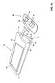
Fig. 1a shows a schematic illustration of an embodiment of the inventive electronic device. -
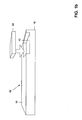
Fig. 1b shows a schematic illustration of another embodiment of the inventive electronic device. -
Fig. 2 shows the usage of the electronic device according to an embodiment of the present invention. -
Fig. 3 shows a flow diagram of a method for operating the electronic device according to an embodiment of the present invention. - First, with reference to
Fig. 1a , an electronic device will be explained which comprises amain unit 10 and aremote control unit 20. Themain unit 10 has amain body 11 in which thereceptacle 12 is formed. Themain body 11 has, according to the embodiment shown inFig. 1a , a flat front plate 13 (also denoted as faceplate), in which, for example, ascreen 14 for displaying images is implemented. Thereceptacle 12 is formed in an outer area of themain unit 10 as shown inFig. 1a such that it borders to three outer surfaces of themain unit 10, namely thefaceplate 13 and two side faces 15 and 16 which are perpendicular to each other and also to thefaceplate 13. Furthermore thereceptacle 12 can be formed such that it has anelevation 17 near oneside face 15 which has less a distance to thefaceplate 13 than acavity 18 which is located in larger distance from a saidside face 15. By such a shape of thereceptacle 20 it is possible that theremote control unit 20 can be securely fixed at themain unit 10 when it is positioned in thereceptacle 12. Expressed in other words theelevation 17 prevents a sideways falling-out of theremote control unit 20 from thereceptacle 12 in direction toside face 15. In this embodiment of theremote control unit 20 should have a shape which preferably fits well into saidreceptacle 12. The lock of theremote control unit 20 in thereceptacle 12 can be achieved by an exact fit of thereceptacle 12 with theremote control unit 20 such that a snap-fit engagement can be realized. Alternatively or in addition it is also possible to provide further engagement means like a hook-and-loop fastener or a plug-in connection in thereceptacle 12 or on the remote control unit 20 (not shown inFig. 1a ). Furthermore, it is possible to magnetically couple theremote control unit 20 to thereceptacle 12. - However, in an alternative embodiment (as shown in
Fig. 1b ) thereceptacle 12 can be formed just in thefaceplate 13 and oneside face 16. In this embodiment a sidewise falling out of theremote control unit 20 from thereceptacle 12 can strongly be prevented but also the flexibility of handling theremote control unit 20 is reduced as only a stripping off of theremote control unit 20 in the direction to the oneside face 16 is possible. - The
remote control unit 20 can comprise input means such asbuttons 22, an on/off-switch 24 or a scrolling-wheel 26. These input means are intended for accepting control actions input to theremote control unit 20 by a user of the electronic device. Such control actions can, for example, be the on/off-switching of themain unit 10, respectively a data processor (not shown inFig. 1a ) in the main unit, the selection of an item from a scroll-down menu 10 (which is also not shown inFig. 1a ) using this scrolling-wheel 26 and selecting the selected item by pressing one of the depictedbuttons 22. Then the remote control unit gererates acontrol signal 19 and (preferably) wirelessly transfers this signal to themain unit 10. Also thebuttons 22 can have different functionalities as it is commonly known, for example, for TV remote control units or DVD remote control units. However, this functionality of thebuttons 22, the on/offswitch 24 and the score 9-wheeled 26 are only for exemplary purposes and shall not be considered to limit the scope of usage of these input means. - As can be seen in
Figure 1b , the scrolling-wheel 26 can be provided on theremote control unit 20 in such a way that it is accessible only when the remote control unit is used detached from themain unit 10. When theremote control unit 20 is arranged in thereceptacle 12, the scrolling-wheel cannot be activated or, in other words, is not accessible. - Summarizing, it is possible to provide input means on the remote control unit in such a way that they are only accessible when the remote control unit is not located inside the receptacle, and that they are not accessible when the remote control unit is positioned in the receptacle.
- The first operation functionality of a the electronic device having said
main unit 10 and saidremote control unit 20 will be described int the following. Firstly, the electronic device (which is preferably a mobile or portable electronic device) can be unpacked from a transportation bag (inFig. 1a also not shown) and theremote control unit 20 is stripped off thereceptacle 12. Following, themain unit 10 is switched on by pressing the on/off-switch 24 of theremote control unit 20. Such steps are roughly depicted in the schematic picture ofFig. 2 . Pressing the on/off-switch 24 results in wirelessly transferring anothercontrol signal 19 from theremote control unit 20 to themain unit 10 which activates the data processor (not shown inFig. 1a ) to start processing data in themain unit 10. This a processing of data can, for example, be a displaying of images onscreen 14 or an outputing of sound via speakers (which are also not shown inFig. 1a ). Alternatively or in addition further data processing operations can be performed in the data processor as for example of performing a navigation calculation, reading of data from storage media, performing image or sound processing steps or the like. The data processing step to be performed by the data processor can thereby be controlled by the input means of the remote controlledunit 20, especially by thebuttons 22 and the scrolling-wheel 26. The control actions are transformed in the remote control action into saidcontrol signal 19 which is then transferred to themain unit 10 respectively to the data processor. However, additional input means can also be provided on a saidremote control unit 20, which can then also be used for controlling the data processing steps in the data processor of themain unit 10. - In a second operation mode the
remote control unit 20 is kept in thereceptacle 12 while all the previously mentioned steps of controlling the data processor of themain unit 10 are performed. In this second operation mode the data transmission from theremote control unit 20 to themain unit 10 can be either performed wirelessly, using the transmitter means of a theremote control unit 20 and the reception means of themain unit 10 as in the first operation mode or alternatively by a plug-in connector which is positioned in or on thereceptacle 12 and theremote control unit 20 respectively. The second operation mode provides the advantage that theremote control unit 20 has not to be stripped-off from thereceptacle 12 when the user is in close proximity to the electronic device. - A main aspect of the present invention can be seen in the fact that the data processor is mainly controlled via the input means of the
remote control unit 20 either in first or in the second operation mode. Theremote control unit 20 can hereby be either stripped-off from the receptacle 12 (first operation mode) or be kept in the receptacle 12 (second operation mode). However, on themain unit 10 there can also be different input means for control actions like further buttons, scrolling-wheels etc. which, preferably, cannot control the same actions which are controlled by the input means of theremote control unit 20. This means that data processing steps which are preformed in response to actions input via the input means of theremote control unit 20 should be only controlled by these input means. Such a configuration of themain unit 10 and theremote control unit 20 provides the advantages that, on the one hand, a loss of theremote control unit 20 can be avoided when the electronic device is used in the second operation mode and, on the other hand, a duplication of input means likebuttons 22, scrolling-wheels 26 on themain unit 10 as well as on theremote control unit 20 can also be avoided, thus reducing production costs for the electronic device. - Furthermore, in another embodiment of the present invention the
remote control unit 20 fits into thereceptacle 12 such that a surface of theremote control unit 20 flushly borders (or abuts) to thefaceplate 13 of the main unit 10 (and preferably also to the side faces 15 and 16) which provides the advantage that theremote control unit 20 shows no extending edges which would lead a user to unintentionally strip-off theremote control unit 20 when operating the electronic device in the the second operation mode, when packing the electronic device into said transportation bag or during the transport of the electronic device in said transportation bag. Thus, the chance of loosing theremote control unit 20 is again reduced. In addition, such an embodiment also reduces the possibility that a user of the electronic device gets hurt. - In another embodiment of the present invention it is also possible that the power supply of the remote control unit, preferably an accumulator, can be inductively charged by a coil in the
main unit 10 which provides the advantage that no separate charging of said power supply is necessary and that the charging and can either be performed in the second operation mode or during the transport in the transportation bag without the need of an extra plug-in connection between the main unit and the remote control unit. This is not only a very user convenient way of charging the power supply of theremote control unit 20 but also a cost effective approach as no connectors are needed. - In another aspect of the present invention a method for operating said electronic device is provided which is more clearly depicted in
Fig. 3 . To be more specific, saidelectronic device 30 has saidmain unit 10, comprising a data processor and thereceptacle 12, as well as saidremote control unit 20. In afirst operation mode 32 the electronic device can be operated (respectively controlled) by theremote control unit 20 being exterior to thereceptacle 12. In this case the control signals resulting from the manually input control actions to theremote control unit 20 are wirelessly transmitted to the main unit thus providing a maximum degree of freedom when moving theremote control unit 20 with respect to themain unit 10. Alternatively, theelectronic device 30 can be operated in thesecond operation mode 34 in which theremote control unit 20 is positioned in thereceptacle 12. Especially the combination of the first and second operation mode provides the high degree of flexibility of the present invention as to reduce the possibility of loosing or forgetting the remote control unit when storing or transporting the electronic device (as the remote control unit is always in the predefined location for it) as well as reducing the production costs of said electronic device due to the fact that no doublication of input means for accepting control actions is needed. - Summarizing it can be stated that remote controls are well known for many devices like TVs, DVD players, home stereos etc. Remotes are also known for mobile devices, like mobile navigation systems or DVD players. The invention describes a remote control, preferably but not only for mobile devices like navigation systems or DVD players, that can be used in two ways. The normal use case is the use as a normal remote controller. In the second use case the remote is locked into the faceplate of the system and becomes part of the fixed, non-remote H in my of the system. A scribble of the invention is attached in
Figs. 1 and2 . This remote control has several advantage as the overall number of buttons can be reduced, since doubles are not required. In the use case "non the remote" the remote controller cannot get lost, since it is plugged into the receptacle of the faceplate of the system.
Claims (17)
- Electronic device comprising:- a main unit (10) having- a data processor which is configured for processing data in response to a control signal;- a receptacle (12),- a remote control unit (20) comprising input means for controlling the electronic device, wherein in a first operating mode, in which the remote control unit (20) is located outside the receptacle (12) of the main unit (10), the remote control unit (20) is configured for providing said control signal (19) via a wireless transmission to said data processor in response to control actions manually input via said input means by a user of the electronic device, andwherein, in a second operating mode, in which the remote control unit (20) is positioned in said receptacle (12) of the main unit (10), the control signal is also generated in response to control actions manually input via said input means of the remote control unit (20).
- Electronic device according to claim 1, characterized in that said remote control unit (20) and said main unit (10) each have a connector which is adapted for transferring said control signal (19) from said remote control unit (20) to said main unit (10) such that in the second operation mode both connectors are directely in contact with each other.
- Electronic device according to claim 1, characterized in that said remote control unit (20) is adapted for transfering the control signal (19) in the second operation mode wirelessly from the remote control unit (20) to the main unit (10).
- Electronic device according to any one of claims 1 to 3, characterized in that said remote control unit (20) is configured for unidirectionally transfering signals, especially said control signal (19), to said main unit (10).
- Electronic device according to any one of claims 1 to 4, characterized in that the main unit (10) has further input means, wherein the data processor is configured for processing the data in response to the control signal received from the remote control unit (20) which was actuated for achieving a first predetermined result wherein said first predetermined result cannot be achieved by actuating said further input means of the main unit (10).
- Electronic device according to any one of claims 1 to 5, characterized in that said main unit (10) is dimensioned to be portable.
- Electronic device according to any one of claims 1 to 6, characterized in that said main unit (10) and the remote control unit (20) are adapted to be connected in a snap-fit engangement in said receptacle (12).
- Electronic device according to any one of claims 1 to 7, characterized in that said main unit (10) has a flat main surface (13), wherein the remote control unit (20) is adapted to fit into said receptacle (12) such that a surface of said remote control unit (20) flushly borders to said main surface (13) of said main unit (14).
- Electronic device according to any one of claims 1 to 8, characterized in that said receptacle (12) is formed in a faceplate (13) and one side surface (16) of said main unit (10).
- Electronic device according to claim 8 or 9, characterized in that said receptacle (12) is located in said faceplate (13) and two side surfaces (15, 16) of the main unit (10) perpendicular to said faceplate (13).
- Electronic device according to claim 10, characterized in that said remote control unit (20) is formed such that it flushly borders to at least one side surface (15, 16) of said main unit (10).
- Electronic device accoding to any one of claims 1 to 11, charactzerized in that said input means (22, 24, 26) of said remote control unit comprises at least one button (22, 24) and/or one scroll wheel (26).
- Electronic device according to any one of claims 1 to 12, charactierized in that said input means of said remote control unit (20) is the only means for receiving control actions by a user of said electronic device.
- Electronic device according to any one of claims 1 to 13, characterized in that said data processor is configured for processing and displaying images and/or outputting sound.
- Electronic device according to claim 14, characterized in that the apparatus is a TV, a DVD player, a home stereo system, a presentation equipement, a navigation system or a note book.
- Electronic device according to any one of claims 1 to 15, characterized in that said remote control unit (20) has an accumulator and means for wirelessly receiving charging power for said accumulator and wherein said main unit (10) is configured for inductively providing charging power for the accumulatior of the remote control unit (20).
- Method for operating an electronic device (30), the electronic device (30) comprising:- a main unit (10) having- a data processor which is configured for processing data in response to a control signal (19);- a receptacle (12),- a remote control unit (20) comprising input means for controlling the electronic device;the method comprising the following steps:operating the electronic device in a first operating mode (32), in which the remote control unit (20) is located outside the receptacle (12) of the main unit (10), and in which the remote control unit (20) provides said control signal (19) via a wireless transmission to said data processor in response to control actions manually input via said input means by a user of the electronic device (30), oroperating the electronic device in a second operating mode (34), in which the remote control unit (20) is positioned in said receptacle (12) of the main unit (10), and in which the control signal (19) is also generated in response to control actions manually input via said input means of the remote control unit (20).
Priority Applications (3)
| Application Number | Priority Date | Filing Date | Title |
|---|---|---|---|
| DE602007001127T DE602007001127D1 (en) | 2007-03-02 | 2007-03-02 | Electronic device controlled by a detachable remote control |
| AT07004350T ATE431585T1 (en) | 2007-03-02 | 2007-03-02 | ELECTRONIC DEVICE CONTROLLED BY A DETACHABLE REMOTE CONTROL |
| EP07004350A EP1965284B1 (en) | 2007-03-02 | 2007-03-02 | Electronic device controlled by an detachable remote control |
Applications Claiming Priority (1)
| Application Number | Priority Date | Filing Date | Title |
|---|---|---|---|
| EP07004350A EP1965284B1 (en) | 2007-03-02 | 2007-03-02 | Electronic device controlled by an detachable remote control |
Publications (2)
| Publication Number | Publication Date |
|---|---|
| EP1965284A1 true EP1965284A1 (en) | 2008-09-03 |
| EP1965284B1 EP1965284B1 (en) | 2009-05-13 |
Family
ID=38030414
Family Applications (1)
| Application Number | Title | Priority Date | Filing Date |
|---|---|---|---|
| EP07004350A Active EP1965284B1 (en) | 2007-03-02 | 2007-03-02 | Electronic device controlled by an detachable remote control |
Country Status (3)
| Country | Link |
|---|---|
| EP (1) | EP1965284B1 (en) |
| AT (1) | ATE431585T1 (en) |
| DE (1) | DE602007001127D1 (en) |
Cited By (1)
| Publication number | Priority date | Publication date | Assignee | Title |
|---|---|---|---|---|
| WO2010133842A1 (en) * | 2009-05-22 | 2010-11-25 | Steritrox Limited | A sterilisation and decontamination device |
Citations (3)
| Publication number | Priority date | Publication date | Assignee | Title |
|---|---|---|---|---|
| US4918439A (en) * | 1987-06-23 | 1990-04-17 | Cl 9, Inc. | Remote control device |
| FR2768975A1 (en) * | 1997-07-25 | 1999-04-02 | E Lead Electronic Co Ltd | AUTOMOBILE ACOUSTIC BLOCK IN WHICH A CELLULAR TELEPHONE MAY BE INTEGRATED |
| DE202005009640U1 (en) * | 2004-08-16 | 2005-10-13 | Mitac Technology Corp. | Mini Remote Control |
-
2007
- 2007-03-02 AT AT07004350T patent/ATE431585T1/en not_active IP Right Cessation
- 2007-03-02 DE DE602007001127T patent/DE602007001127D1/en active Active
- 2007-03-02 EP EP07004350A patent/EP1965284B1/en active Active
Patent Citations (3)
| Publication number | Priority date | Publication date | Assignee | Title |
|---|---|---|---|---|
| US4918439A (en) * | 1987-06-23 | 1990-04-17 | Cl 9, Inc. | Remote control device |
| FR2768975A1 (en) * | 1997-07-25 | 1999-04-02 | E Lead Electronic Co Ltd | AUTOMOBILE ACOUSTIC BLOCK IN WHICH A CELLULAR TELEPHONE MAY BE INTEGRATED |
| DE202005009640U1 (en) * | 2004-08-16 | 2005-10-13 | Mitac Technology Corp. | Mini Remote Control |
Cited By (5)
| Publication number | Priority date | Publication date | Assignee | Title |
|---|---|---|---|---|
| WO2010133842A1 (en) * | 2009-05-22 | 2010-11-25 | Steritrox Limited | A sterilisation and decontamination device |
| CN102458486A (en) * | 2009-05-22 | 2012-05-16 | 斯特里特罗克斯有限公司 | A sterilisation and decontamination device |
| JP2012527279A (en) * | 2009-05-22 | 2012-11-08 | ステリトロックス・リミテッド | Sterilization and decontamination equipment |
| US9072804B2 (en) | 2009-05-22 | 2015-07-07 | Dow Global Technologies, Llc | Sterilisation and decontamination device |
| CN102458486B (en) * | 2009-05-22 | 2015-12-16 | 陶氏环球技术有限责任公司 | Sterilization and cleaning equipment |
Also Published As
| Publication number | Publication date |
|---|---|
| ATE431585T1 (en) | 2009-05-15 |
| DE602007001127D1 (en) | 2009-06-25 |
| EP1965284B1 (en) | 2009-05-13 |
Similar Documents
| Publication | Publication Date | Title |
|---|---|---|
| US20230306829A1 (en) | Systems and methods for protecting retail display merchandise from theft | |
| US8939838B2 (en) | Accessory for playing games with a portable electronic device | |
| US7253765B2 (en) | Detachable remote controller for an electronic entertainment device and method for using the same | |
| CN104919464B (en) | For the method and apparatus of wireless control medical instrument | |
| EP3348316B1 (en) | Accessory device | |
| US20250095461A1 (en) | System and method for calibrating a wireless security range | |
| JP4843514B2 (en) | Wireless transmission device | |
| US9602907B2 (en) | Earbud charging case | |
| EP1958045B1 (en) | System including a hand-held wireless graphical input device and a computer device. | |
| US20150212612A1 (en) | Control System for Augmenting a Portable Touch Screen Device | |
| KR20150007534A (en) | Digital device amd method for controlling the same | |
| CN103109462A (en) | Wearable motion sensing computing interface | |
| CN101938564A (en) | Electronic device with bluetooth headset | |
| JP6187354B2 (en) | Cover for mobile device | |
| US11449115B2 (en) | Method for receiving power from other external device connected to electronic device, on basis of disconnection of external electronic device that is supplying power, and electronic device implementing same | |
| EP1965284B1 (en) | Electronic device controlled by an detachable remote control | |
| KR102279396B1 (en) | Electronic device, input device and method for controlling electronic device using input device | |
| US9030406B2 (en) | Remote control functionality including information from motion sensors | |
| JP2011004164A (en) | Communication equipment, communication aid method and communication aid program | |
| CN111371204A (en) | Charging method and electric energy transfer device | |
| HK40104072A (en) | Mobile wireless audio transmission system and charging/conveying dock | |
| KR20110000221U (en) | Digital camera and camcorder that has the removable LCD screen which can be used as a romote control device. | |
| EP1777946A2 (en) | A remote commander | |
| JP2007324826A (en) | Television broadcast receiver and electronic equipment |
Legal Events
| Date | Code | Title | Description |
|---|---|---|---|
| PUAI | Public reference made under article 153(3) epc to a published international application that has entered the european phase |
Free format text: ORIGINAL CODE: 0009012 |
|
| 17P | Request for examination filed |
Effective date: 20070823 |
|
| AK | Designated contracting states |
Kind code of ref document: A1 Designated state(s): AT BE BG CH CY CZ DE DK EE ES FI FR GB GR HU IE IS IT LI LT LU LV MC MT NL PL PT RO SE SI SK TR |
|
| AX | Request for extension of the european patent |
Extension state: AL BA HR MK RS |
|
| GRAP | Despatch of communication of intention to grant a patent |
Free format text: ORIGINAL CODE: EPIDOSNIGR1 |
|
| GRAS | Grant fee paid |
Free format text: ORIGINAL CODE: EPIDOSNIGR3 |
|
| GRAA | (expected) grant |
Free format text: ORIGINAL CODE: 0009210 |
|
| AKX | Designation fees paid |
Designated state(s): AT BE BG CH CY CZ DE DK EE ES FI FR GB GR HU IE IS IT LI LT LU LV MC MT NL PL PT RO SE SI SK TR |
|
| AK | Designated contracting states |
Kind code of ref document: B1 Designated state(s): AT BE BG CH CY CZ DE DK EE ES FI FR GB GR HU IE IS IT LI LT LU LV MC MT NL PL PT RO SE SI SK TR |
|
| REG | Reference to a national code |
Ref country code: GB Ref legal event code: FG4D |
|
| REG | Reference to a national code |
Ref country code: CH Ref legal event code: EP |
|
| REG | Reference to a national code |
Ref country code: IE Ref legal event code: FG4D |
|
| REF | Corresponds to: |
Ref document number: 602007001127 Country of ref document: DE Date of ref document: 20090625 Kind code of ref document: P |
|
| PG25 | Lapsed in a contracting state [announced via postgrant information from national office to epo] |
Ref country code: PT Free format text: LAPSE BECAUSE OF FAILURE TO SUBMIT A TRANSLATION OF THE DESCRIPTION OR TO PAY THE FEE WITHIN THE PRESCRIBED TIME-LIMIT Effective date: 20090913 Ref country code: AT Free format text: LAPSE BECAUSE OF FAILURE TO SUBMIT A TRANSLATION OF THE DESCRIPTION OR TO PAY THE FEE WITHIN THE PRESCRIBED TIME-LIMIT Effective date: 20090513 Ref country code: LT Free format text: LAPSE BECAUSE OF FAILURE TO SUBMIT A TRANSLATION OF THE DESCRIPTION OR TO PAY THE FEE WITHIN THE PRESCRIBED TIME-LIMIT Effective date: 20090513 Ref country code: FI Free format text: LAPSE BECAUSE OF FAILURE TO SUBMIT A TRANSLATION OF THE DESCRIPTION OR TO PAY THE FEE WITHIN THE PRESCRIBED TIME-LIMIT Effective date: 20090513 Ref country code: ES Free format text: LAPSE BECAUSE OF FAILURE TO SUBMIT A TRANSLATION OF THE DESCRIPTION OR TO PAY THE FEE WITHIN THE PRESCRIBED TIME-LIMIT Effective date: 20090824 |
|
| NLV1 | Nl: lapsed or annulled due to failure to fulfill the requirements of art. 29p and 29m of the patents act | ||
| PG25 | Lapsed in a contracting state [announced via postgrant information from national office to epo] |
Ref country code: PL Free format text: LAPSE BECAUSE OF FAILURE TO SUBMIT A TRANSLATION OF THE DESCRIPTION OR TO PAY THE FEE WITHIN THE PRESCRIBED TIME-LIMIT Effective date: 20090513 Ref country code: NL Free format text: LAPSE BECAUSE OF FAILURE TO SUBMIT A TRANSLATION OF THE DESCRIPTION OR TO PAY THE FEE WITHIN THE PRESCRIBED TIME-LIMIT Effective date: 20090513 Ref country code: IS Free format text: LAPSE BECAUSE OF FAILURE TO SUBMIT A TRANSLATION OF THE DESCRIPTION OR TO PAY THE FEE WITHIN THE PRESCRIBED TIME-LIMIT Effective date: 20090913 Ref country code: SE Free format text: LAPSE BECAUSE OF FAILURE TO SUBMIT A TRANSLATION OF THE DESCRIPTION OR TO PAY THE FEE WITHIN THE PRESCRIBED TIME-LIMIT Effective date: 20090813 Ref country code: SI Free format text: LAPSE BECAUSE OF FAILURE TO SUBMIT A TRANSLATION OF THE DESCRIPTION OR TO PAY THE FEE WITHIN THE PRESCRIBED TIME-LIMIT Effective date: 20090513 Ref country code: LV Free format text: LAPSE BECAUSE OF FAILURE TO SUBMIT A TRANSLATION OF THE DESCRIPTION OR TO PAY THE FEE WITHIN THE PRESCRIBED TIME-LIMIT Effective date: 20090513 |
|
| PG25 | Lapsed in a contracting state [announced via postgrant information from national office to epo] |
Ref country code: EE Free format text: LAPSE BECAUSE OF FAILURE TO SUBMIT A TRANSLATION OF THE DESCRIPTION OR TO PAY THE FEE WITHIN THE PRESCRIBED TIME-LIMIT Effective date: 20090513 Ref country code: DK Free format text: LAPSE BECAUSE OF FAILURE TO SUBMIT A TRANSLATION OF THE DESCRIPTION OR TO PAY THE FEE WITHIN THE PRESCRIBED TIME-LIMIT Effective date: 20090513 Ref country code: CZ Free format text: LAPSE BECAUSE OF FAILURE TO SUBMIT A TRANSLATION OF THE DESCRIPTION OR TO PAY THE FEE WITHIN THE PRESCRIBED TIME-LIMIT Effective date: 20090513 |
|
| PG25 | Lapsed in a contracting state [announced via postgrant information from national office to epo] |
Ref country code: BE Free format text: LAPSE BECAUSE OF FAILURE TO SUBMIT A TRANSLATION OF THE DESCRIPTION OR TO PAY THE FEE WITHIN THE PRESCRIBED TIME-LIMIT Effective date: 20090513 Ref country code: SK Free format text: LAPSE BECAUSE OF FAILURE TO SUBMIT A TRANSLATION OF THE DESCRIPTION OR TO PAY THE FEE WITHIN THE PRESCRIBED TIME-LIMIT Effective date: 20090513 |
|
| PLBE | No opposition filed within time limit |
Free format text: ORIGINAL CODE: 0009261 |
|
| STAA | Information on the status of an ep patent application or granted ep patent |
Free format text: STATUS: NO OPPOSITION FILED WITHIN TIME LIMIT |
|
| PG25 | Lapsed in a contracting state [announced via postgrant information from national office to epo] |
Ref country code: BG Free format text: LAPSE BECAUSE OF FAILURE TO SUBMIT A TRANSLATION OF THE DESCRIPTION OR TO PAY THE FEE WITHIN THE PRESCRIBED TIME-LIMIT Effective date: 20090813 |
|
| 26N | No opposition filed |
Effective date: 20100216 |
|
| PG25 | Lapsed in a contracting state [announced via postgrant information from national office to epo] |
Ref country code: GR Free format text: LAPSE BECAUSE OF FAILURE TO SUBMIT A TRANSLATION OF THE DESCRIPTION OR TO PAY THE FEE WITHIN THE PRESCRIBED TIME-LIMIT Effective date: 20090814 Ref country code: MC Free format text: LAPSE BECAUSE OF NON-PAYMENT OF DUE FEES Effective date: 20100331 |
|
| PG25 | Lapsed in a contracting state [announced via postgrant information from national office to epo] |
Ref country code: IE Free format text: LAPSE BECAUSE OF NON-PAYMENT OF DUE FEES Effective date: 20100302 |
|
| PG25 | Lapsed in a contracting state [announced via postgrant information from national office to epo] |
Ref country code: MT Free format text: LAPSE BECAUSE OF FAILURE TO SUBMIT A TRANSLATION OF THE DESCRIPTION OR TO PAY THE FEE WITHIN THE PRESCRIBED TIME-LIMIT Effective date: 20090513 |
|
| PGRI | Patent reinstated in contracting state [announced from national office to epo] |
Ref country code: IT Effective date: 20110501 |
|
| REG | Reference to a national code |
Ref country code: CH Ref legal event code: PL |
|
| PG25 | Lapsed in a contracting state [announced via postgrant information from national office to epo] |
Ref country code: LI Free format text: LAPSE BECAUSE OF NON-PAYMENT OF DUE FEES Effective date: 20110331 Ref country code: CH Free format text: LAPSE BECAUSE OF NON-PAYMENT OF DUE FEES Effective date: 20110331 |
|
| PG25 | Lapsed in a contracting state [announced via postgrant information from national office to epo] |
Ref country code: CY Free format text: LAPSE BECAUSE OF FAILURE TO SUBMIT A TRANSLATION OF THE DESCRIPTION OR TO PAY THE FEE WITHIN THE PRESCRIBED TIME-LIMIT Effective date: 20090513 |
|
| PG25 | Lapsed in a contracting state [announced via postgrant information from national office to epo] |
Ref country code: HU Free format text: LAPSE BECAUSE OF FAILURE TO SUBMIT A TRANSLATION OF THE DESCRIPTION OR TO PAY THE FEE WITHIN THE PRESCRIBED TIME-LIMIT Effective date: 20091114 Ref country code: LU Free format text: LAPSE BECAUSE OF NON-PAYMENT OF DUE FEES Effective date: 20100302 |
|
| PG25 | Lapsed in a contracting state [announced via postgrant information from national office to epo] |
Ref country code: TR Free format text: LAPSE BECAUSE OF FAILURE TO SUBMIT A TRANSLATION OF THE DESCRIPTION OR TO PAY THE FEE WITHIN THE PRESCRIBED TIME-LIMIT Effective date: 20090513 |
|
| PG25 | Lapsed in a contracting state [announced via postgrant information from national office to epo] |
Ref country code: RO Free format text: LAPSE BECAUSE OF FAILURE TO SUBMIT A TRANSLATION OF THE DESCRIPTION OR TO PAY THE FEE WITHIN THE PRESCRIBED TIME-LIMIT Effective date: 20090513 |
|
| REG | Reference to a national code |
Ref country code: FR Ref legal event code: PLFP Year of fee payment: 9 |
|
| PGFP | Annual fee paid to national office [announced via postgrant information from national office to epo] |
Ref country code: IT Payment date: 20150324 Year of fee payment: 9 |
|
| PGFP | Annual fee paid to national office [announced via postgrant information from national office to epo] |
Ref country code: FR Payment date: 20150317 Year of fee payment: 9 |
|
| REG | Reference to a national code |
Ref country code: FR Ref legal event code: ST Effective date: 20161130 |
|
| PG25 | Lapsed in a contracting state [announced via postgrant information from national office to epo] |
Ref country code: FR Free format text: LAPSE BECAUSE OF NON-PAYMENT OF DUE FEES Effective date: 20160331 |
|
| PG25 | Lapsed in a contracting state [announced via postgrant information from national office to epo] |
Ref country code: IT Free format text: LAPSE BECAUSE OF NON-PAYMENT OF DUE FEES Effective date: 20160302 |
|
| PGFP | Annual fee paid to national office [announced via postgrant information from national office to epo] |
Ref country code: GB Payment date: 20210219 Year of fee payment: 15 |
|
| GBPC | Gb: european patent ceased through non-payment of renewal fee |
Effective date: 20220302 |
|
| PG25 | Lapsed in a contracting state [announced via postgrant information from national office to epo] |
Ref country code: GB Free format text: LAPSE BECAUSE OF NON-PAYMENT OF DUE FEES Effective date: 20220302 |
|
| P01 | Opt-out of the competence of the unified patent court (upc) registered |
Effective date: 20230526 |
|
| PGFP | Annual fee paid to national office [announced via postgrant information from national office to epo] |
Ref country code: DE Payment date: 20260219 Year of fee payment: 20 |