EP1965216A2 - Automatic analyzer - Google Patents
Automatic analyzer Download PDFInfo
- Publication number
- EP1965216A2 EP1965216A2 EP20080003375 EP08003375A EP1965216A2 EP 1965216 A2 EP1965216 A2 EP 1965216A2 EP 20080003375 EP20080003375 EP 20080003375 EP 08003375 A EP08003375 A EP 08003375A EP 1965216 A2 EP1965216 A2 EP 1965216A2
- Authority
- EP
- European Patent Office
- Prior art keywords
- user
- result
- automatic analyzer
- screen
- Prior art date
- Legal status (The legal status is an assumption and is not a legal conclusion. Google has not performed a legal analysis and makes no representation as to the accuracy of the status listed.)
- Granted
Links
Images




Classifications
-
- G—PHYSICS
- G01—MEASURING; TESTING
- G01N—INVESTIGATING OR ANALYSING MATERIALS BY DETERMINING THEIR CHEMICAL OR PHYSICAL PROPERTIES
- G01N35/00—Automatic analysis not limited to methods or materials provided for in any single one of groups G01N1/00 - G01N33/00; Handling materials therefor
- G01N35/00584—Control arrangements for automatic analysers
- G01N35/00722—Communications; Identification
-
- G—PHYSICS
- G01—MEASURING; TESTING
- G01N—INVESTIGATING OR ANALYSING MATERIALS BY DETERMINING THEIR CHEMICAL OR PHYSICAL PROPERTIES
- G01N35/00—Automatic analysis not limited to methods or materials provided for in any single one of groups G01N1/00 - G01N33/00; Handling materials therefor
- G01N35/00584—Control arrangements for automatic analysers
- G01N35/00722—Communications; Identification
- G01N2035/00891—Displaying information to the operator
Definitions
- the present invention relates to an automatic analyzer for performing qualitative/quantitative analysis of biological samples such as blood and urine, and more particularly to an automatic analyzer that includes a display unit for displaying information including the measurement result of biological samples.
- Automatic analyzers which perform qualitative/quantitative analysis of specific components included in biological samples such as blood and urine, are coming into remarkably wide use mainly in large-scale hospitals, and clinical laboratory test centers, in which it is necessary to handle a large number of samples/items in a short period of time. For this reason, the high measurement precision, high repeatability, high throughput per unit time, and low running costs are required for such automatic analyzers.
- automatic analyzers are provided with: a mode in which the measurement result of a biological sample is printed by an actual printer in real time; and a paperless mode in which a printing image is merely displayed on a display unit without actually printing the printing image.
- the output mode used differs for each facility.
- the automatic analyzers have various kinds of maintenance functions of maintaining the performance of the automatic analyzers.
- the automatic analyzers have various kinds of real-time/batch printing functions of printing the result of executed maintenance, a situation of a reagent used for analysis, the result of calibration, precision control data, and the like, if necessary.
- the print output results are summarized, and are then displayed in time series as a printing image on a result display screen.
- an automatic analyzer as disclosed in JP-A-8-211064 is known as this kind of automatic analyzer.
- the conventional automatic analyzer displays various kinds of output results, which are acquired by the automatic analyzer, in time series as one printing image. Therefore, in the present situation, it is not possible to know the result included in each page without actual browsing of each page in succession.
- the output result targeted by a user may be acquired based on the paging operation of the user, which causes a hindrance to quick operation required in the clinical laboratory test.
- the user prints the targeted output result from a result output screen to paper for printing, and then confirms/verifies the measurement result of each sample on the printing paper. Accordingly, in the present situation, the user is forced to input a check indicating whether or not the measurement result has been checked, and a comment if necessary, and then the user files and saves the print if necessary.
- An object of the present invention is to provide an automatic analyzer that is capable of decreasing a load placed on a user who confirms/verifies the measurement result of biological samples, the maintenance execution result, and the like, and that enables the quick clinical laboratory test operation.
- an automatic analyzer for analyzing a biological sample
- the automatic analyzer comprising: a display unit for displaying a list of pieces of information including measurement results of the biological sample; and control means for performing control so that, on each piece of information including the measurement results of the biological sample, information as to when and who has executed verification/confirmation of data can be displayed on the display unit.
- an automatic analyzer may also be provided with a function of enabling a user to add a check indicating whether or not the user has checked the result, the check date, a checker, a comment, and the like, to the measurement result of each biological sample, and the like, on a display unit including a print result screen for displaying the measurement result of the biological sample as a time-series printing image, the measurement result being output by the automatic analyzer.
- the automatic analyzer may also be provided with various functions based on selection of the output result targeted by a user from among all printed results output by the automatic analyzer, on a display unit that includes a screen for displaying a list including a title of printing, the date and time of printing, an operator ID, a range of page, and user's check indicating whether or not the user has checked the measurement result.
- Examples of the various functions include a function of proceeding to a start page of the targeted output result so that the targeted output result is displayed; a function of extracting only the output result targeted by the user so that the targeted output result is displayed; a function of printing only the output result targeted by the user on printing paper by a printer; and a function of enabling a user to save only the output result targeted by the user in an outside medium as a printing image by an external storage device.
- the automatic analyzer may also be provided with a function of, by selecting and registering only print results required for a user among all printed results output by the automatic analyzer, enabling the user to display only a list of the selected print results so that it is easier for the user to search for the print results targeted by the user.
- a user can easily display a targeted result display screen, and can perform on a screen all confirmation/verification work of the measurement result acquired up to that time.
- Fig. 1 is a diagram schematically illustrating a configuration of an automatic analyzer.
- Fig. 4 is a diagram illustrating a processing method for achieving the present invention.
- reference numeral 101 denotes an operation unit.
- the operation unit is a computer that is equipped with peripheral devices including: a keyboard 102 for inputting data; a display unit 103 for displaying data; a printer 104 for printing data; an interface 105 through which a connection to an analyzing unit is made; an internal storage device 106 for storing data; and an external storage device 107 for storing data.
- Reference numeral 108 denotes one or more analyzing units.
- the analyzing unit 108 is connected to the operation unit 101 through the interface 105.
- the analyzing unit 108 executes measurements of biological samples, the maintenance operation, and the like, according to an operation instruction received from the display unit 103.
- the execution operation is totally controlled by the computer 109.
- the result of the executed measurements of the biological samples, the result of the executed maintenance, and the like, are stored in the storage device 106 of the operation unit 101 through the interface 105.
- the measurement result and the maintenance execution result are edited in an actual print format to form print data 403 (a print edit function 402 shown in Fig. 4 ).
- the print data 403 is then displayed on the display unit 103, or printed by the printer 104 (a print function 404).
- Fig. 2 is a diagram illustrating a print result screen, and a menu screen that is displayed from the print result screen.
- the print result screen 201 displays the measurement result of the biological samples, the maintenance execution result, and the like, as a time-series printing image.
- a print result menu screen 203 which is displayed by pressing a menu button 202 of the print result screen 201, displays a list (a display function 405) including all of the printed results output by the automatic analyzer.
- the displayed list includes a title of printing, the date and time of printing, an operator ID, a range of page, and a user's check indicating whether or not a user has checked the result.
- each print data about the title of printing, the date and time of printing, and the range of page is successively collated, followed by being stored in a database as list information.
- a user is allowed to select a plurality of target print results (reference numeral 204). For the selected print results, the user can execute each function by pressing each corresponding button of "Move” 205, "Extract” 206, "Print” 207, or "Save” 208.
- the list displayed on the menu screen can be collated by sorting the fields of the title of printing, the date and time of printing, the operator ID, the range of page, and the user's check (reference numeral 211) .
- the print result menu screen 203 is closed, and then a start page of the print result selected by the user is displayed on the print result screen 201.
- the print result menu screen 203 is closed, and then the print result screen 201 is displayed with only the print result selected by the user extracted (an extraction function 406).
- an extraction radio button 209 of the print result screen 201 is switched to "extracted”. If the screen is returned to a screen with no extraction, the extraction radio button 209 is switched to "not extracted”.
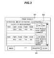
- Fig. 3 is a diagram illustrating a print result screen 301 on which the measurement result of biological samples is displayed through the operation from the print result menu screen 203.
- An area 302 is displayed on the print result screen 301 together with the actual measurement result.
- the area 302 is used to input a check mark indicating whether or not data has been checked, the check date, a checker, a comment, and the like.
- the color of a "Register” button 303 changes to prompt the user to register the data.
- the "Register” button 303 is pressed, the data, which has been inputted by the user up to this time, is collectively registered (reference numeral 408). Then, the color of the "Register” button is returned. As a result of this operation, the print result in question is displayed as "checked" on the print result menu screen 203.
- Fig. 5 is a diagram illustrating a menu setting screen that is displayed by pressing a "Set” button 210 of the print result menu screen shown in Fig. 2 .
- print items are displayed in a candidate list 502.
- An arbitrary print item is moved to a print target list 505 by use of a "Select” button 503.
- an arbitrary print item included in the print target list 505 is excluded from the print target list 505 by use of a "Release” button 504.
- the operation of selection/cancel causes the color of a "Return” button 506 to change and then pressing the "Return” button 506 closes the menu setting screen 501.
- the print result menu screen 203 displays only the print items selected on the menu setting screen 501.
Landscapes
- Physics & Mathematics (AREA)
- Health & Medical Sciences (AREA)
- Life Sciences & Earth Sciences (AREA)
- Chemical & Material Sciences (AREA)
- Analytical Chemistry (AREA)
- Biochemistry (AREA)
- General Health & Medical Sciences (AREA)
- General Physics & Mathematics (AREA)
- Immunology (AREA)
- Pathology (AREA)
- Automatic Analysis And Handling Materials Therefor (AREA)
- Management, Administration, Business Operations System, And Electronic Commerce (AREA)
Abstract
Description
- The present invention relates to an automatic analyzer for performing qualitative/quantitative analysis of biological samples such as blood and urine, and more particularly to an automatic analyzer that includes a display unit for displaying information including the measurement result of biological samples.
- Automatic analyzers, which perform qualitative/quantitative analysis of specific components included in biological samples such as blood and urine, are coming into remarkably wide use mainly in large-scale hospitals, and clinical laboratory test centers, in which it is necessary to handle a large number of samples/items in a short period of time. For this reason, the high measurement precision, high repeatability, high throughput per unit time, and low running costs are required for such automatic analyzers.
- In order to satisfy many user needs, for example, automatic analyzers are provided with: a mode in which the measurement result of a biological sample is printed by an actual printer in real time; and a paperless mode in which a printing image is merely displayed on a display unit without actually printing the printing image. The output mode used differs for each facility.
- In addition, the automatic analyzers have various kinds of maintenance functions of maintaining the performance of the automatic analyzers. Moreover, the automatic analyzers have various kinds of real-time/batch printing functions of printing the result of executed maintenance, a situation of a reagent used for analysis, the result of calibration, precision control data, and the like, if necessary. The print output results are summarized, and are then displayed in time series as a printing image on a result display screen.
- Incidentally, for example, an automatic analyzer as disclosed in
JP-A-8-211064 - The conventional automatic analyzer displays various kinds of output results, which are acquired by the automatic analyzer, in time series as one printing image. Therefore, in the present situation, it is not possible to know the result included in each page without actual browsing of each page in succession.
- Accordingly, the output result targeted by a user may be acquired based on the paging operation of the user, which causes a hindrance to quick operation required in the clinical laboratory test.
- In addition, for the data verification/confirm of the measurement result, the user prints the targeted output result from a result output screen to paper for printing, and then confirms/verifies the measurement result of each sample on the printing paper. Accordingly, in the present situation, the user is forced to input a check indicating whether or not the measurement result has been checked, and a comment if necessary, and then the user files and saves the print if necessary.
- An object of the present invention is to provide an automatic analyzer that is capable of decreasing a load placed on a user who confirms/verifies the measurement result of biological samples, the maintenance execution result, and the like, and that enables the quick clinical laboratory test operation.
- In order to achieve the above-described object, according to one aspect of the present invention, there is provided an automatic analyzer for analyzing a biological sample, the automatic analyzer comprising: a display unit for displaying a list of pieces of information including measurement results of the biological sample; and control means for performing control so that, on each piece of information including the measurement results of the biological sample, information as to when and who has executed verification/confirmation of data can be displayed on the display unit.
- In addition, an automatic analyzer may also be provided with a function of enabling a user to add a check indicating whether or not the user has checked the result, the check date, a checker, a comment, and the like, to the measurement result of each biological sample, and the like, on a display unit including a print result screen for displaying the measurement result of the biological sample as a time-series printing image, the measurement result being output by the automatic analyzer.
- Moreover, the automatic analyzer may also be provided with various functions based on selection of the output result targeted by a user from among all printed results output by the automatic analyzer, on a display unit that includes a screen for displaying a list including a title of printing, the date and time of printing, an operator ID, a range of page, and user's check indicating whether or not the user has checked the measurement result. Examples of the various functions include a function of proceeding to a start page of the targeted output result so that the targeted output result is displayed; a function of extracting only the output result targeted by the user so that the targeted output result is displayed; a function of printing only the output result targeted by the user on printing paper by a printer; and a function of enabling a user to save only the output result targeted by the user in an outside medium as a printing image by an external storage device.
- Furthermore, the automatic analyzer may also be provided with a function of, by selecting and registering only print results required for a user among all printed results output by the automatic analyzer, enabling the user to display only a list of the selected print results so that it is easier for the user to search for the print results targeted by the user.
- According to the present invention, a user can easily display a targeted result display screen, and can perform on a screen all confirmation/verification work of the measurement result acquired up to that time. In addition, it is also possible to print the check result displayed on the screen just as it is, or to save the check result in an outside medium just as it is, if necessary. Therefore, it is expected that an improvement in work efficiency can be achieved.
-
-
Fig. 1 is a diagram schematically illustrating an overall configuration of an automatic analyzer; -
Fig. 2 is a diagram illustrating a print result screen, and a menu screen that is displayed from the print result screen; -
Fig. 3 is a diagram illustrating a print result screen on which the measurement result of biological samples is displayed; -
Fig. 4 is a diagram illustrating a processing method for achieving the present invention; and -
Fig. 5 is a diagram illustrating a menu setting screen that is displayed from a print result menu screen. - Embodiments of the present invention will be described with reference to accompanying drawings as below.
-
Fig. 1 is a diagram schematically illustrating a configuration of an automatic analyzer.Fig. 4 is a diagram illustrating a processing method for achieving the present invention. - In
Fig. 1 ,reference numeral 101 denotes an operation unit. The operation unit is a computer that is equipped with peripheral devices including: akeyboard 102 for inputting data; adisplay unit 103 for displaying data; aprinter 104 for printing data; aninterface 105 through which a connection to an analyzing unit is made; aninternal storage device 106 for storing data; and anexternal storage device 107 for storing data. -
Reference numeral 108 denotes one or more analyzing units. The analyzingunit 108 is connected to theoperation unit 101 through theinterface 105. The analyzingunit 108 executes measurements of biological samples, the maintenance operation, and the like, according to an operation instruction received from thedisplay unit 103. The execution operation is totally controlled by thecomputer 109. - The result of the executed measurements of the biological samples, the result of the executed maintenance, and the like, are stored in the
storage device 106 of theoperation unit 101 through theinterface 105. In addition, the measurement result and the maintenance execution result are edited in an actual print format to form print data 403 (aprint edit function 402 shown inFig. 4 ). Theprint data 403 is then displayed on thedisplay unit 103, or printed by the printer 104 (a print function 404). -
Fig. 2 is a diagram illustrating a print result screen, and a menu screen that is displayed from the print result screen. - The
print result screen 201 displays the measurement result of the biological samples, the maintenance execution result, and the like, as a time-series printing image. In addition, a printresult menu screen 203, which is displayed by pressing amenu button 202 of theprint result screen 201, displays a list (a display function 405) including all of the printed results output by the automatic analyzer. For example, the displayed list includes a title of printing, the date and time of printing, an operator ID, a range of page, and a user's check indicating whether or not a user has checked the result. - In the course of creating
print data 403 from adatabase 401 stored in thestorage device 106, each print data about the title of printing, the date and time of printing, and the range of page is successively collated, followed by being stored in a database as list information. - On the print
result menu screen 203, a user is allowed to select a plurality of target print results (reference numeral 204). For the selected print results, the user can execute each function by pressing each corresponding button of "Move" 205, "Extract" 206, "Print" 207, or "Save" 208. - In addition, the list displayed on the menu screen can be collated by sorting the fields of the title of printing, the date and time of printing, the operator ID, the range of page, and the user's check (reference numeral 211) .
- When the "Move"
button 205 is pressed, the printresult menu screen 203 is closed, and then a start page of the print result selected by the user is displayed on theprint result screen 201. - When the "Extract"
button 206 is pressed, the printresult menu screen 203 is closed, and then theprint result screen 201 is displayed with only the print result selected by the user extracted (an extraction function 406). Incidentally, in this case, anextraction radio button 209 of theprint result screen 201 is switched to "extracted". If the screen is returned to a screen with no extraction, theextraction radio button 209 is switched to "not extracted". - When the "Print"
button 207 is pressed, only the print result selected by the user is printed on printing paper by the printer 104 (the print function 404). - When the "Save"
button 208 is pressed, only the print result selected by the user is saved in an outside medium as a printing image by the external storage device 107 (a save function 407). -
Fig. 3 is a diagram illustrating aprint result screen 301 on which the measurement result of biological samples is displayed through the operation from the printresult menu screen 203. - An
area 302 is displayed on theprint result screen 301 together with the actual measurement result. Thearea 302 is used to input a check mark indicating whether or not data has been checked, the check date, a checker, a comment, and the like. - When a user inputs data into the
area 302, the color of a "Register"button 303 changes to prompt the user to register the data. When the "Register"button 303 is pressed, the data, which has been inputted by the user up to this time, is collectively registered (reference numeral 408). Then, the color of the "Register" button is returned. As a result of this operation, the print result in question is displayed as "checked" on the printresult menu screen 203. -
Fig. 5 is a diagram illustrating a menu setting screen that is displayed by pressing a "Set"button 210 of the print result menu screen shown inFig. 2 . - On the
menu setting screen 501, print items are displayed in acandidate list 502. An arbitrary print item is moved to aprint target list 505 by use of a "Select"button 503. On the other hand, an arbitrary print item included in theprint target list 505 is excluded from theprint target list 505 by use of a "Release"button 504. In actuality, the operation of selection/cancel causes the color of a "Return"button 506 to change and then pressing the "Return"button 506 closes themenu setting screen 501. Then, the printresult menu screen 203 displays only the print items selected on themenu setting screen 501.
Claims (6)
- An automatic analyzer for analyzing a biological sample, said automatic analyzer comprising:a display unit for displaying a list of pieces of information including measurement results of the biological sample; andcontrol means for performing control so that, on each piece of information including the measurement results of the biological sample, information as to when and who has executed verification/confirmation of data can be displayed on the display unit.
- The automatic analyzer according to Claim 1, further comprising:input means for inputting information as to when and who has executed verification/confirmation of data.
- The automatic analyzer according to Claim 1, further comprising:selection means for, on the display unit, selecting output results targeted by a user from among the listed pieces of information, andcontrol means for performing control so that the information selected by the selection means is displayed.
- The automatic analyzer according to Claim 3, further comprising:control means for performing control so that only information selected by the selection means is displayed on the display unit.
- The automatic analyzer according to Claim 3, further comprising:control means for performing control so that only information selected by the selection means is printed by a printer.
- The automatic analyzer according to Claim 3, wherein:only information selected by the selection means can be saved in an outside medium as a printing image through an external storage device.
Applications Claiming Priority (1)
| Application Number | Priority Date | Filing Date | Title |
|---|---|---|---|
| JP2007048353A JP2008209326A (en) | 2007-02-28 | 2007-02-28 | Automatic analyzer |
Publications (3)
| Publication Number | Publication Date |
|---|---|
| EP1965216A2 true EP1965216A2 (en) | 2008-09-03 |
| EP1965216A3 EP1965216A3 (en) | 2015-05-27 |
| EP1965216B1 EP1965216B1 (en) | 2018-10-24 |
Family
ID=39483235
Family Applications (1)
| Application Number | Title | Priority Date | Filing Date |
|---|---|---|---|
| EP08003375.6A Not-in-force EP1965216B1 (en) | 2007-02-28 | 2008-02-25 | Automatic analyzer |
Country Status (4)
| Country | Link |
|---|---|
| US (1) | US20080208481A1 (en) |
| EP (1) | EP1965216B1 (en) |
| JP (1) | JP2008209326A (en) |
| CN (1) | CN101271121A (en) |
Families Citing this family (8)
| Publication number | Priority date | Publication date | Assignee | Title |
|---|---|---|---|---|
| EP2116851B1 (en) * | 2008-02-13 | 2018-09-19 | Hitachi High-Technologies Corporation | Automatic analyzer |
| CN102124347B (en) * | 2008-09-03 | 2014-10-15 | 株式会社日立高新技术 | Automatic analyzer |
| JP2013167561A (en) * | 2012-02-16 | 2013-08-29 | Hitachi High-Technologies Corp | Automatic analyzer |
| JP2013210937A (en) * | 2012-03-30 | 2013-10-10 | Sysmex Corp | Analysis result providing system, specimen analysis system, analysis result providing apparatus, method of providing specimen analysis result, and computer program |
| WO2017098650A1 (en) * | 2015-12-11 | 2017-06-15 | 株式会社島津製作所 | Analysis information management system |
| EP3413262A4 (en) * | 2015-12-11 | 2020-07-08 | Shimadzu Corporation | ANALYSIS INFORMATION MANAGEMENT SYSTEM |
| EP3422014B1 (en) * | 2017-06-27 | 2024-07-24 | F. Hoffmann-La Roche AG | Laboratory system |
| JP7229440B2 (en) | 2020-12-07 | 2023-02-27 | 三菱電機株式会社 | LEARNING DATA GENERATION DEVICE AND LEARNING DATA GENERATION METHOD |
Citations (1)
| Publication number | Priority date | Publication date | Assignee | Title |
|---|---|---|---|---|
| JPH08211064A (en) | 1995-02-02 | 1996-08-20 | Hitachi Ltd | Automatic analyzer |
Family Cites Families (22)
| Publication number | Priority date | Publication date | Assignee | Title |
|---|---|---|---|---|
| JP3597958B2 (en) * | 1996-11-15 | 2004-12-08 | 株式会社日立製作所 | Automatic analyzer |
| JPH11296605A (en) * | 1998-04-13 | 1999-10-29 | Hitachi Ltd | Clinical test system |
| DE69926168T2 (en) * | 1998-04-21 | 2006-01-12 | Hitachi, Ltd. | Automatic analysis device with adjustable operating function limitation |
| US6275150B1 (en) * | 1998-07-14 | 2001-08-14 | Bayer Corporation | User interface for a biomedical analyzer system |
| JP2000215196A (en) * | 1999-01-22 | 2000-08-04 | Hitachi Ltd | Document display system |
| JP2001357179A (en) * | 2000-06-09 | 2001-12-26 | Ntt Comware Corp | Business support apparatus, business support method, and recording medium recording business support program |
| US7251610B2 (en) * | 2000-09-20 | 2007-07-31 | Epic Systems Corporation | Clinical documentation system for use by multiple caregivers |
| US20050101841A9 (en) * | 2001-12-04 | 2005-05-12 | Kimberly-Clark Worldwide, Inc. | Healthcare networks with biosensors |
| JP2003329690A (en) * | 2002-05-09 | 2003-11-19 | Sysmex Corp | Clinical examination system |
| JP2004220599A (en) * | 2002-12-27 | 2004-08-05 | Moss Institute Co Ltd | Test information management system, test information management device, test information management method, and test information management program |
| JP4045999B2 (en) * | 2003-04-11 | 2008-02-13 | 株式会社島津製作所 | Data analysis device for instrument analysis |
| JP4807927B2 (en) * | 2003-07-08 | 2011-11-02 | シャープ株式会社 | Communication relay device |
| US7185288B2 (en) * | 2003-07-18 | 2007-02-27 | Dade Behring Inc. | Operator interface module segmented by function in an automatic clinical analyzer |
| JP2005108209A (en) * | 2003-09-11 | 2005-04-21 | Mitsubishi Kagaku Bio-Clinical Laboratories Inc | Clinical trial test management system |
| JP2005283332A (en) * | 2004-03-30 | 2005-10-13 | Shimadzu Corp | Validation system and validation program |
| JP2005321200A (en) * | 2004-05-06 | 2005-11-17 | Shimadzu Corp | Data analysis device for instrument analysis |
| JP2006084281A (en) * | 2004-09-15 | 2006-03-30 | Hitachi Software Eng Co Ltd | Spot image recognition method and spot image recognition system |
| JP2006105800A (en) * | 2004-10-06 | 2006-04-20 | Shimadzu Corp | Analysis system, information aggregate used in the system, and recording medium storing the information aggregate |
| JP2006189282A (en) * | 2005-01-05 | 2006-07-20 | Hitachi High-Technologies Corp | Automatic analyzer |
| JP2006275895A (en) * | 2005-03-30 | 2006-10-12 | Olympus Corp | Method for displaying measurement information on living body-related material |
| JP4103910B2 (en) * | 2005-09-26 | 2008-06-18 | 株式会社日立製作所 | Analysis result management method and apparatus |
| JP4669368B2 (en) * | 2005-10-03 | 2011-04-13 | シスメックス株式会社 | Biological sample analyzer |
-
2007
- 2007-02-28 JP JP2007048353A patent/JP2008209326A/en active Pending
-
2008
- 2008-02-20 CN CNA2008100096719A patent/CN101271121A/en active Pending
- 2008-02-25 EP EP08003375.6A patent/EP1965216B1/en not_active Not-in-force
- 2008-02-26 US US12/037,614 patent/US20080208481A1/en not_active Abandoned
Patent Citations (1)
| Publication number | Priority date | Publication date | Assignee | Title |
|---|---|---|---|---|
| JPH08211064A (en) | 1995-02-02 | 1996-08-20 | Hitachi Ltd | Automatic analyzer |
Also Published As
| Publication number | Publication date |
|---|---|
| EP1965216B1 (en) | 2018-10-24 |
| JP2008209326A (en) | 2008-09-11 |
| CN101271121A (en) | 2008-09-24 |
| US20080208481A1 (en) | 2008-08-28 |
| EP1965216A3 (en) | 2015-05-27 |
Similar Documents
| Publication | Publication Date | Title |
|---|---|---|
| EP1965216B1 (en) | Automatic analyzer | |
| JP5753792B2 (en) | Automatic analyzer | |
| US11036777B2 (en) | Analysis information management system | |
| JP3656692B2 (en) | Clinical examination system and examination status management method | |
| CN101135693B (en) | Automatic analyzer | |
| EP3779461B1 (en) | Automated analysis device | |
| EP4012417B1 (en) | Automatic analysis system and alarm handling method | |
| EP1672370A1 (en) | Automatic blood chemistry analyser with sample volume measurement | |
| JP2004502179A (en) | Computer interface module with flat menu | |
| CN102346181B (en) | Urine sample testing apparatus and apparatus for processing measurement result of urine sample | |
| JP2009539078A (en) | System and method for managing sample test results and respective result context information | |
| JPH0749346A (en) | Urine sediment inspection device | |
| JP2015180862A (en) | Measuring apparatus and measuring method | |
| JP4550852B2 (en) | Test information management system, test information management device, test information management program, test information management method, and sample container set | |
| JP7175153B2 (en) | SIMULATION METHOD AND DEVICE FOR ANALYZER | |
| EP2187327A1 (en) | Method for graphically processing displayed data records for minimizing a selection error rate | |
| JPH03211463A (en) | Console panel, operation card, and operating method of automatic analyzing device | |
| US11125765B2 (en) | Automatic analyzer | |
| JP4499633B2 (en) | Automatic analyzer and clinical test system | |
| CN114720217A (en) | Smear preparation device, sample analysis system and smear preparation method | |
| JP2009168732A (en) | Automatic analyzer | |
| JP2002255140A (en) | Label adhering device and program for label adhering device | |
| CN120407884A (en) | Biological sample experimental status display method, device and biological sample analysis system | |
| JP2006145429A (en) | Clinical examination system | |
| CN118464757A (en) | Flow cytometry immunophenotyping test method, device, equipment and storage medium |
Legal Events
| Date | Code | Title | Description |
|---|---|---|---|
| PUAI | Public reference made under article 153(3) epc to a published international application that has entered the european phase |
Free format text: ORIGINAL CODE: 0009012 |
|
| 17P | Request for examination filed |
Effective date: 20080331 |
|
| AK | Designated contracting states |
Kind code of ref document: A2 Designated state(s): AT BE BG CH CY CZ DE DK EE ES FI FR GB GR HR HU IE IS IT LI LT LU LV MC MT NL NO PL PT RO SE SI SK TR |
|
| AX | Request for extension of the european patent |
Extension state: AL BA MK RS |
|
| PUAL | Search report despatched |
Free format text: ORIGINAL CODE: 0009013 |
|
| AK | Designated contracting states |
Kind code of ref document: A3 Designated state(s): AT BE BG CH CY CZ DE DK EE ES FI FR GB GR HR HU IE IS IT LI LT LU LV MC MT NL NO PL PT RO SE SI SK TR |
|
| AX | Request for extension of the european patent |
Extension state: AL BA MK RS |
|
| RIC1 | Information provided on ipc code assigned before grant |
Ipc: G01N 35/00 20060101AFI20150421BHEP |
|
| AKX | Designation fees paid |
Designated state(s): AT BE BG CH CY CZ DE DK EE ES FI FR GB GR HR HU IE IS IT LI LT LU LV MC MT NL NO PL PT RO SE SI SK TR |
|
| AXX | Extension fees paid |
Extension state: RS Extension state: MK Extension state: BA Extension state: AL |
|
| 17Q | First examination report despatched |
Effective date: 20160429 |
|
| STAA | Information on the status of an ep patent application or granted ep patent |
Free format text: STATUS: EXAMINATION IS IN PROGRESS |
|
| GRAP | Despatch of communication of intention to grant a patent |
Free format text: ORIGINAL CODE: EPIDOSNIGR1 |
|
| STAA | Information on the status of an ep patent application or granted ep patent |
Free format text: STATUS: GRANT OF PATENT IS INTENDED |
|
| INTG | Intention to grant announced |
Effective date: 20180523 |
|
| RAP1 | Party data changed (applicant data changed or rights of an application transferred) |
Owner name: HITACHI HIGH-TECHNOLOGIES CORPORATION |
|
| GRAS | Grant fee paid |
Free format text: ORIGINAL CODE: EPIDOSNIGR3 |
|
| GRAA | (expected) grant |
Free format text: ORIGINAL CODE: 0009210 |
|
| STAA | Information on the status of an ep patent application or granted ep patent |
Free format text: STATUS: THE PATENT HAS BEEN GRANTED |
|
| AK | Designated contracting states |
Kind code of ref document: B1 Designated state(s): AT BE BG CH CY CZ DE DK EE ES FI FR GB GR HR HU IE IS IT LI LT LU LV MC MT NL NO PL PT RO SE SI SK TR |
|
| REG | Reference to a national code |
Ref country code: GB Ref legal event code: FG4D |
|
| REG | Reference to a national code |
Ref country code: CH Ref legal event code: EP |
|
| REG | Reference to a national code |
Ref country code: IE Ref legal event code: FG4D |
|
| REG | Reference to a national code |
Ref country code: AT Ref legal event code: REF Ref document number: 1057314 Country of ref document: AT Kind code of ref document: T Effective date: 20181115 |
|
| REG | Reference to a national code |
Ref country code: DE Ref legal event code: R096 Ref document number: 602008057521 Country of ref document: DE |
|
| REG | Reference to a national code |
Ref country code: NL Ref legal event code: MP Effective date: 20181024 |
|
| REG | Reference to a national code |
Ref country code: LT Ref legal event code: MG4D |
|
| REG | Reference to a national code |
Ref country code: AT Ref legal event code: MK05 Ref document number: 1057314 Country of ref document: AT Kind code of ref document: T Effective date: 20181024 |
|
| PG25 | Lapsed in a contracting state [announced via postgrant information from national office to epo] |
Ref country code: NL Free format text: LAPSE BECAUSE OF FAILURE TO SUBMIT A TRANSLATION OF THE DESCRIPTION OR TO PAY THE FEE WITHIN THE PRESCRIBED TIME-LIMIT Effective date: 20181024 |
|
| PG25 | Lapsed in a contracting state [announced via postgrant information from national office to epo] |
Ref country code: BG Free format text: LAPSE BECAUSE OF FAILURE TO SUBMIT A TRANSLATION OF THE DESCRIPTION OR TO PAY THE FEE WITHIN THE PRESCRIBED TIME-LIMIT Effective date: 20190124 Ref country code: ES Free format text: LAPSE BECAUSE OF FAILURE TO SUBMIT A TRANSLATION OF THE DESCRIPTION OR TO PAY THE FEE WITHIN THE PRESCRIBED TIME-LIMIT Effective date: 20181024 Ref country code: LT Free format text: LAPSE BECAUSE OF FAILURE TO SUBMIT A TRANSLATION OF THE DESCRIPTION OR TO PAY THE FEE WITHIN THE PRESCRIBED TIME-LIMIT Effective date: 20181024 Ref country code: IS Free format text: LAPSE BECAUSE OF FAILURE TO SUBMIT A TRANSLATION OF THE DESCRIPTION OR TO PAY THE FEE WITHIN THE PRESCRIBED TIME-LIMIT Effective date: 20190224 Ref country code: NO Free format text: LAPSE BECAUSE OF FAILURE TO SUBMIT A TRANSLATION OF THE DESCRIPTION OR TO PAY THE FEE WITHIN THE PRESCRIBED TIME-LIMIT Effective date: 20190124 Ref country code: AT Free format text: LAPSE BECAUSE OF FAILURE TO SUBMIT A TRANSLATION OF THE DESCRIPTION OR TO PAY THE FEE WITHIN THE PRESCRIBED TIME-LIMIT Effective date: 20181024 Ref country code: LV Free format text: LAPSE BECAUSE OF FAILURE TO SUBMIT A TRANSLATION OF THE DESCRIPTION OR TO PAY THE FEE WITHIN THE PRESCRIBED TIME-LIMIT Effective date: 20181024 Ref country code: PL Free format text: LAPSE BECAUSE OF FAILURE TO SUBMIT A TRANSLATION OF THE DESCRIPTION OR TO PAY THE FEE WITHIN THE PRESCRIBED TIME-LIMIT Effective date: 20181024 Ref country code: HR Free format text: LAPSE BECAUSE OF FAILURE TO SUBMIT A TRANSLATION OF THE DESCRIPTION OR TO PAY THE FEE WITHIN THE PRESCRIBED TIME-LIMIT Effective date: 20181024 Ref country code: FI Free format text: LAPSE BECAUSE OF FAILURE TO SUBMIT A TRANSLATION OF THE DESCRIPTION OR TO PAY THE FEE WITHIN THE PRESCRIBED TIME-LIMIT Effective date: 20181024 |
|
| PG25 | Lapsed in a contracting state [announced via postgrant information from national office to epo] |
Ref country code: SE Free format text: LAPSE BECAUSE OF FAILURE TO SUBMIT A TRANSLATION OF THE DESCRIPTION OR TO PAY THE FEE WITHIN THE PRESCRIBED TIME-LIMIT Effective date: 20181024 Ref country code: GR Free format text: LAPSE BECAUSE OF FAILURE TO SUBMIT A TRANSLATION OF THE DESCRIPTION OR TO PAY THE FEE WITHIN THE PRESCRIBED TIME-LIMIT Effective date: 20190125 Ref country code: PT Free format text: LAPSE BECAUSE OF FAILURE TO SUBMIT A TRANSLATION OF THE DESCRIPTION OR TO PAY THE FEE WITHIN THE PRESCRIBED TIME-LIMIT Effective date: 20190224 |
|
| REG | Reference to a national code |
Ref country code: DE Ref legal event code: R097 Ref document number: 602008057521 Country of ref document: DE |
|
| PG25 | Lapsed in a contracting state [announced via postgrant information from national office to epo] |
Ref country code: CZ Free format text: LAPSE BECAUSE OF FAILURE TO SUBMIT A TRANSLATION OF THE DESCRIPTION OR TO PAY THE FEE WITHIN THE PRESCRIBED TIME-LIMIT Effective date: 20181024 Ref country code: IT Free format text: LAPSE BECAUSE OF FAILURE TO SUBMIT A TRANSLATION OF THE DESCRIPTION OR TO PAY THE FEE WITHIN THE PRESCRIBED TIME-LIMIT Effective date: 20181024 Ref country code: DK Free format text: LAPSE BECAUSE OF FAILURE TO SUBMIT A TRANSLATION OF THE DESCRIPTION OR TO PAY THE FEE WITHIN THE PRESCRIBED TIME-LIMIT Effective date: 20181024 |
|
| PG25 | Lapsed in a contracting state [announced via postgrant information from national office to epo] |
Ref country code: EE Free format text: LAPSE BECAUSE OF FAILURE TO SUBMIT A TRANSLATION OF THE DESCRIPTION OR TO PAY THE FEE WITHIN THE PRESCRIBED TIME-LIMIT Effective date: 20181024 Ref country code: RO Free format text: LAPSE BECAUSE OF FAILURE TO SUBMIT A TRANSLATION OF THE DESCRIPTION OR TO PAY THE FEE WITHIN THE PRESCRIBED TIME-LIMIT Effective date: 20181024 Ref country code: SK Free format text: LAPSE BECAUSE OF FAILURE TO SUBMIT A TRANSLATION OF THE DESCRIPTION OR TO PAY THE FEE WITHIN THE PRESCRIBED TIME-LIMIT Effective date: 20181024 |
|
| PLBE | No opposition filed within time limit |
Free format text: ORIGINAL CODE: 0009261 |
|
| STAA | Information on the status of an ep patent application or granted ep patent |
Free format text: STATUS: NO OPPOSITION FILED WITHIN TIME LIMIT |
|
| REG | Reference to a national code |
Ref country code: CH Ref legal event code: PL |
|
| 26N | No opposition filed |
Effective date: 20190725 |
|
| GBPC | Gb: european patent ceased through non-payment of renewal fee |
Effective date: 20190225 |
|
| PG25 | Lapsed in a contracting state [announced via postgrant information from national office to epo] |
Ref country code: LU Free format text: LAPSE BECAUSE OF NON-PAYMENT OF DUE FEES Effective date: 20190225 Ref country code: MC Free format text: LAPSE BECAUSE OF FAILURE TO SUBMIT A TRANSLATION OF THE DESCRIPTION OR TO PAY THE FEE WITHIN THE PRESCRIBED TIME-LIMIT Effective date: 20181024 Ref country code: SI Free format text: LAPSE BECAUSE OF FAILURE TO SUBMIT A TRANSLATION OF THE DESCRIPTION OR TO PAY THE FEE WITHIN THE PRESCRIBED TIME-LIMIT Effective date: 20181024 |
|
| REG | Reference to a national code |
Ref country code: BE Ref legal event code: MM Effective date: 20190228 |
|
| REG | Reference to a national code |
Ref country code: IE Ref legal event code: MM4A |
|
| PG25 | Lapsed in a contracting state [announced via postgrant information from national office to epo] |
Ref country code: CH Free format text: LAPSE BECAUSE OF NON-PAYMENT OF DUE FEES Effective date: 20190228 Ref country code: LI Free format text: LAPSE BECAUSE OF NON-PAYMENT OF DUE FEES Effective date: 20190228 |
|
| PG25 | Lapsed in a contracting state [announced via postgrant information from national office to epo] |
Ref country code: IE Free format text: LAPSE BECAUSE OF NON-PAYMENT OF DUE FEES Effective date: 20190225 Ref country code: GB Free format text: LAPSE BECAUSE OF NON-PAYMENT OF DUE FEES Effective date: 20190225 |
|
| PG25 | Lapsed in a contracting state [announced via postgrant information from national office to epo] |
Ref country code: BE Free format text: LAPSE BECAUSE OF NON-PAYMENT OF DUE FEES Effective date: 20190228 |
|
| PG25 | Lapsed in a contracting state [announced via postgrant information from national office to epo] |
Ref country code: TR Free format text: LAPSE BECAUSE OF FAILURE TO SUBMIT A TRANSLATION OF THE DESCRIPTION OR TO PAY THE FEE WITHIN THE PRESCRIBED TIME-LIMIT Effective date: 20181024 |
|
| PG25 | Lapsed in a contracting state [announced via postgrant information from national office to epo] |
Ref country code: MT Free format text: LAPSE BECAUSE OF NON-PAYMENT OF DUE FEES Effective date: 20190225 |
|
| REG | Reference to a national code |
Ref country code: DE Ref legal event code: R082 Ref document number: 602008057521 Country of ref document: DE Representative=s name: STREHL SCHUEBEL-HOPF & PARTNER MBB PATENTANWAE, DE Ref country code: DE Ref legal event code: R081 Ref document number: 602008057521 Country of ref document: DE Owner name: HITACHI HIGH-TECH CORPORATION, JP Free format text: FORMER OWNER: HITACHI HIGH-TECHNOLOGIES CORPORATION, TOKYO, JP |
|
| PG25 | Lapsed in a contracting state [announced via postgrant information from national office to epo] |
Ref country code: CY Free format text: LAPSE BECAUSE OF FAILURE TO SUBMIT A TRANSLATION OF THE DESCRIPTION OR TO PAY THE FEE WITHIN THE PRESCRIBED TIME-LIMIT Effective date: 20181024 |
|
| PG25 | Lapsed in a contracting state [announced via postgrant information from national office to epo] |
Ref country code: HU Free format text: LAPSE BECAUSE OF FAILURE TO SUBMIT A TRANSLATION OF THE DESCRIPTION OR TO PAY THE FEE WITHIN THE PRESCRIBED TIME-LIMIT; INVALID AB INITIO Effective date: 20080225 |
|
| PGFP | Annual fee paid to national office [announced via postgrant information from national office to epo] |
Ref country code: DE Payment date: 20231229 Year of fee payment: 17 |
|
| PGFP | Annual fee paid to national office [announced via postgrant information from national office to epo] |
Ref country code: FR Payment date: 20240103 Year of fee payment: 17 |
|
| REG | Reference to a national code |
Ref country code: DE Ref legal event code: R119 Ref document number: 602008057521 Country of ref document: DE |
|
| PG25 | Lapsed in a contracting state [announced via postgrant information from national office to epo] |
Ref country code: DE Free format text: LAPSE BECAUSE OF NON-PAYMENT OF DUE FEES Effective date: 20250902 |
|
| PG25 | Lapsed in a contracting state [announced via postgrant information from national office to epo] |
Ref country code: FR Free format text: LAPSE BECAUSE OF NON-PAYMENT OF DUE FEES Effective date: 20250228 |