EP1965098A2 - Transmission control system - Google Patents
Transmission control system Download PDFInfo
- Publication number
- EP1965098A2 EP1965098A2 EP08250669A EP08250669A EP1965098A2 EP 1965098 A2 EP1965098 A2 EP 1965098A2 EP 08250669 A EP08250669 A EP 08250669A EP 08250669 A EP08250669 A EP 08250669A EP 1965098 A2 EP1965098 A2 EP 1965098A2
- Authority
- EP
- European Patent Office
- Prior art keywords
- mode
- gear
- gear ratio
- section
- temporarily
- Prior art date
- Legal status (The legal status is an assumption and is not a legal conclusion. Google has not performed a legal analysis and makes no representation as to the accuracy of the status listed.)
- Granted
Links
Images





Classifications
-
- F—MECHANICAL ENGINEERING; LIGHTING; HEATING; WEAPONS; BLASTING
- F16—ENGINEERING ELEMENTS AND UNITS; GENERAL MEASURES FOR PRODUCING AND MAINTAINING EFFECTIVE FUNCTIONING OF MACHINES OR INSTALLATIONS; THERMAL INSULATION IN GENERAL
- F16H—GEARING
- F16H61/00—Control functions within control units of change-speed- or reversing-gearings for conveying rotary motion ; Control of exclusively fluid gearing, friction gearing, gearings with endless flexible members or other particular types of gearing
- F16H61/66—Control functions within control units of change-speed- or reversing-gearings for conveying rotary motion ; Control of exclusively fluid gearing, friction gearing, gearings with endless flexible members or other particular types of gearing specially adapted for continuously variable gearings
- F16H61/662—Control functions within control units of change-speed- or reversing-gearings for conveying rotary motion ; Control of exclusively fluid gearing, friction gearing, gearings with endless flexible members or other particular types of gearing specially adapted for continuously variable gearings with endless flexible members
- F16H61/66254—Control functions within control units of change-speed- or reversing-gearings for conveying rotary motion ; Control of exclusively fluid gearing, friction gearing, gearings with endless flexible members or other particular types of gearing specially adapted for continuously variable gearings with endless flexible members controlling of shifting being influenced by a signal derived from the engine and the main coupling
- F16H61/66259—Control functions within control units of change-speed- or reversing-gearings for conveying rotary motion ; Control of exclusively fluid gearing, friction gearing, gearings with endless flexible members or other particular types of gearing specially adapted for continuously variable gearings with endless flexible members controlling of shifting being influenced by a signal derived from the engine and the main coupling using electrical or electronical sensing or control means
-
- B—PERFORMING OPERATIONS; TRANSPORTING
- B62—LAND VEHICLES FOR TRAVELLING OTHERWISE THAN ON RAILS
- B62K—CYCLES; CYCLE FRAMES; CYCLE STEERING DEVICES; RIDER-OPERATED TERMINAL CONTROLS SPECIALLY ADAPTED FOR CYCLES; CYCLE AXLE SUSPENSIONS; CYCLE SIDECARS, FORECARS, OR THE LIKE
- B62K11/00—Motorcycles, engine-assisted cycles or motor scooters with one or two wheels
- B62K11/14—Handlebar constructions, or arrangements of controls thereon, specially adapted thereto
-
- B—PERFORMING OPERATIONS; TRANSPORTING
- B62—LAND VEHICLES FOR TRAVELLING OTHERWISE THAN ON RAILS
- B62K—CYCLES; CYCLE FRAMES; CYCLE STEERING DEVICES; RIDER-OPERATED TERMINAL CONTROLS SPECIALLY ADAPTED FOR CYCLES; CYCLE AXLE SUSPENSIONS; CYCLE SIDECARS, FORECARS, OR THE LIKE
- B62K2202/00—Motorised scooters
-
- F—MECHANICAL ENGINEERING; LIGHTING; HEATING; WEAPONS; BLASTING
- F16—ENGINEERING ELEMENTS AND UNITS; GENERAL MEASURES FOR PRODUCING AND MAINTAINING EFFECTIVE FUNCTIONING OF MACHINES OR INSTALLATIONS; THERMAL INSULATION IN GENERAL
- F16H—GEARING
- F16H59/00—Control inputs to control units of change-speed- or reversing-gearings for conveying rotary motion
- F16H59/02—Selector apparatus
- F16H2059/0221—Selector apparatus for selecting modes, e.g. sport, normal, economy
-
- F—MECHANICAL ENGINEERING; LIGHTING; HEATING; WEAPONS; BLASTING
- F16—ENGINEERING ELEMENTS AND UNITS; GENERAL MEASURES FOR PRODUCING AND MAINTAINING EFFECTIVE FUNCTIONING OF MACHINES OR INSTALLATIONS; THERMAL INSULATION IN GENERAL
- F16H—GEARING
- F16H61/00—Control functions within control units of change-speed- or reversing-gearings for conveying rotary motion ; Control of exclusively fluid gearing, friction gearing, gearings with endless flexible members or other particular types of gearing
- F16H61/66—Control functions within control units of change-speed- or reversing-gearings for conveying rotary motion ; Control of exclusively fluid gearing, friction gearing, gearings with endless flexible members or other particular types of gearing specially adapted for continuously variable gearings
- F16H2061/6604—Special control features generally applicable to continuously variable gearings
- F16H2061/6615—Imitating a stepped transmissions
- F16H2061/6616—Imitating a stepped transmissions the shifting of the transmission being manually controlled
-
- F—MECHANICAL ENGINEERING; LIGHTING; HEATING; WEAPONS; BLASTING
- F16—ENGINEERING ELEMENTS AND UNITS; GENERAL MEASURES FOR PRODUCING AND MAINTAINING EFFECTIVE FUNCTIONING OF MACHINES OR INSTALLATIONS; THERMAL INSULATION IN GENERAL
- F16H—GEARING
- F16H59/00—Control inputs to control units of change-speed- or reversing-gearings for conveying rotary motion
- F16H59/02—Selector apparatus
Definitions
- the present invention relates to a control and a transmission of a straddle type vehicle, a transmission, and also relates to the straddle type vehicle.
- ECVT Electronically controlled continuously variable transmissions
- the gear ratio is automatically changed based upon a gear ratio map indicative of relationships among vehicle speeds, engine speeds (accelerator openings) and gear ratios.
- vehicles incorporating an ECVT hereunder, called “vehicle incorporating the ECVT”
- vehicle incorporating the ECVT do not require any gear change operations or clutch operations by a rider. Therefore, recently, the ECVT is incorporated in various vehicles.
- the rider cannot change the gear ratios optionally out of the setting given in the gear ratio map, with the vehicle incorporating the ECVT.
- the rider has difficulty in effectively activating engine braking at will with the vehicle incorporating the ECVT. More specifically, it is difficult for the rider to activate the engine brake more strongly than that given by the gear ratio map.
- a vehicle incorporating the ECVT whereby both of the so-called automatic transmission (AT) mode in which the gear ratios can be continuously and automatically changed and the so-called manual transmission (MT) mode in which the gear ratios can be changed optionally by the rider are selectable.
- AT automatic transmission
- MT manual transmission
- JP-A-04-131588 proposes an ECVT whereby gear ratios of a continuously variable transmission can be manually set in accordance with positions of a deceleration lever.
- JP-A-62-175228 proposes an ECVT whereby gear ratios can be forcibly changed or an ECVT having a switch with which a shift down operation can be manually made.
- the conventional vehicle incorporating the ECVT that is changeable between the AT mode and the MT mode requires complicated and troublesome operations when the shift down operation is intentionally made in the AT mode to accelerate or decelerate the vehicle. Specifically, in the AT mode, at least the following three operations are necessary for increase or decrease the vehicle speed by shifting down intentionally.
- the present invention is made in view of the above points and aims to make it practicable that an intentional shift down operation is easily made in the AT mode.
- a control system adapted for use with an electronically controlled continuously variable transmission located between a driving source and a driving wheel of a vehicle, said control system comprising:
- the MT mode may include an automatic MT mode in which the gear ratio control section automatically changes a gear ratio of the transmission among the plurality of predetermined gear ratios in accordance with a driving state of the straddle type vehicle.
- the MT mode may include a manual MT mode in which the gear ratio control section changes a gear ratio of the transmission among the plurality of predetermined gear ratios in accordance with an operation of a rider of the straddle type vehicle.
- the control system may further comprise:
- the release signal outputting section may output a release signal when a predetermined period elapses after the MT mode is temporarily selected by the MT mode temporarily selecting section.
- the release signal outputting section may output a release signal when a brake of an associated vehicle is operated.
- the control system may further comprise:
- the release signal outputting section may output a release signal when the mode change signal is outputted after the MT mode is temporarily selected by the MT mode temporarily selecting section.
- the control system may further comprise a shift down switch for outputting a shift down signal.
- the gear ratio control section may change the gear ratio of the transmission to one of the plurality of predetermined gear ratios which is lower than the current gear ratio, when the mode change signal is outputted during a period in which the MT mode is temporarily selected by the MT mode temporarily selecting section.
- the mode temporarily changing switch may comprise a push type switch which outputs the mode change signal when the switch is activated.
- the shift down switch may be adapted to shift down the transmission when the gear change mode selecting section selects the MT mode.
- the shift down switch and the mode temporarily changing switch may be comprised in a single switch.
- the control system may further comprise a mode selecting switch for outputting a mode selecting signal, whereby the gear change mode selecting section selects one of the plurality of gear change modes.
- a transmission comprising:
- vehicle comprising:
- the mode temporarily changing switch may be located where a rider can operate the switch by their thumb.
- the vehicle may further comprise handlebars including a right grip and a left grip for a rider to hold, wherein the mode temporarily changing switch is located on a right side of the left grip.
- the vehicle may comprise a straddle type vehicle.
- a control system for an electronically controlled transmission disposed between a drive source and a drive wheel of a straddle type vehicle and being capable of continuously changing a gear ratio.
- the straddle type vehicle has a mode temporarily changing switch.
- the mode temporarily changing switch outputs a mode change signal to the control system.
- the control system in accordance with the present invention includes a gear ratio control section, a gear change mode selecting section, a release signal outputting section, an MT mode temporarily selecting section and an AT mode returning section.
- the gear ratio control section controls the gear ratio of the transmission.
- the gear change mode selecting section selects one of a plurality of gear change modes.
- the plurality of gear change modes include an AT mode and an MT mode.
- the gear ratio control section continuously changes the gear ratio of the transmission in accordance with a running state of the straddle type vehicle.
- the gear ratio control section changes the gear ratio of the transmission among predetermined multiple gear ratios.
- the release signal outputting section outputs a release signal when a predetermined operation is made to the straddle type vehicle and when a predetermined condition is satisfied in connection with the straddle type vehicle.
- the MT mode temporarily selecting section makes the gear change mode selecting section temporarily select the MT mode when the mode change signal is inputted under a condition that the AT mode is selected by the gear change mode selecting section.
- the MT mode temporarily selecting section also makes the gear ratio control section change the gear ratio of the transmission to one of gear ratios existing in a LOW range which is lower than a current gear ratio of the transmission within the predetermined multiple gear ratios.
- the AT mode returning section returns the gear change mode selected by the gear change mode selecting section to the AT mode when the release signal is outputted after the MT mode is temporarily selected by the MT mode temporarily selecting section.
- a transmission having an electronically controlled gear change mechanism and a control system for controlling the gear change mechanism.
- the electronically controlled gear change mechanism is disposed between a drive source and a drive wheel of a straddle type vehicle, and being capable of continuously changing a gear ratio.
- the control system controls the gear change mechanism.
- the straddle type vehicle has a mode temporarily changing switch.
- the mode temporarily changing switch outputs a mode change signal to the control system.
- the control system includes a gear ratio control section, a gear change mode selecting section, a release signal outputting section, an MT mode temporarily selecting section and AT mode returning section.
- the gear ratio control section controls the gear ratio of the gear change mechanism.
- the gear change mode selecting section selects one of a plurality of gear change modes.
- the plurality of gear change modes include an AT mode and an MT mode.
- the gear ratio control section continuously changes the gear ratio of the gear change mechanism in accordance with a running state of the straddle type vehicle.
- the gear ratio control section changes the gear ratio of the gear change mechanism among predetermined multiple gear ratios.
- the release signal outputting section outputs a release signal when a predetermined operation is made to the straddle type vehicle and when a predetermined condition is satisfied in connection with the straddle type vehicle.
- the MT mode temporarily selecting section makes the gear change mode selecting section temporarily select the MT mode when the mode change signal is inputted under a condition that the AT mode is selected by the gear change mode selecting section.
- the MT mode temporarily selecting section also makes the gear ratio control section change the gear ratio of the gear change mechanism to one of gear ratios existing in a LOW range which is lower than a current gear ratio of the gear change mechanism within the predetermined multiple gear ratios.
- the AT mode returning section returns the gear change mode selected by the gear change mode selecting section to the AT mode when the release signal is outputted after the MT mode is temporarily selected by the MT mode temporarily selecting section.
- a straddle type vehicle which includes a drive source, a drive wheel and a transmission.
- the drive wheel is driven by the drive source.
- the transmission has an electronically controlled gear change mechanism and a control system.
- the gear change mechanism is disposed between the drive source and the drive wheel and is capable of continuously changing a gear ratio.
- the control system controls the gear change mechanism.
- the straddle type vehicle in accordance with the present invention includes a mode temporarily changing switch.
- the mode temporarily changing switch outputs a mode change signal to the control system.
- the control system includes a gear ratio control section, a gear change mode selecting section, a release signal outputting section, an MT mode temporarily selecting section and AT mode returning section.
- the gear ratio control section controls the gear ratio of the gear change mechanism.
- the gear change mode selecting section selects one of a plurality of gear change modes.
- the plurality of gear change modes include an AT mode and an MT mode.
- the gear ratio control section continuously changes the gear ratio of the gear change mechanism in accordance with a running state of the straddle type vehicle.
- the gear ratio control section changes the gear ratio of the gear change mechanism among predetermined multiple gear ratios.
- the release signal outputting section outputs a release signal when a predetermined operation is made to the straddle type vehicle and when a predetermined condition is satisfied in connection with the straddle type vehicle.
- the MT mode temporarily selecting section makes the gear change mode selecting section temporarily select the MT mode when the mode change signal is inputted under a condition that the AT mode is selected by the gear change mode selecting section.
- the MT mode temporarily selecting section also makes the gear ratio control section change the gear ratio of the gear change mechanism to one of gear ratios existing in a LOW range which is lower than a current gear ratio of the gear change mechanism within the predetermined multiple gear ratios.
- the AT mode returning section returns the gear change mode selected by the gear change mode selecting section to the AT mode when the release signal is outputted after the MT mode is temporarily selected by the MT mode temporarily selecting section.
- an intentional shift down operation can be easily made in the AT mode.
- the motorcycle 1 in the form of a so-called scooter type.
- the motorcycle 1 has a steering handle 4, a power unit 2 and a rear wheel 3 functioning as a drive wheel.
- the power unit 2 and the rear wheel 3 are connected to each other through a power transmission mechanism 6.
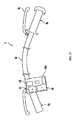
- FIG. 2 is a schematic structural view of the steering handle 4.
- the steering handle 4 has a handle bar 4d coupled with a steering head pipe which is not shown.
- the steering handle 4 includes a left grip section 4a positioned at the left end of the handle bar 4d and a right grip section 4b positioned at the right end of the handle bar 4d.
- the right grip section 4b is pivotable relative to the handle bar 4d.
- a throttle valve which is not shown is operated to control a throttle opening.
- Brake levers 4c are disposed adjacent to the respective grip sections 4a, 4b.
- brakes (not shown) of the motorcycle 1 are actuated and, as described later, a brake signal 104 is outputted to an ECU 5.
- a switch box 40a is disposed in a right side portion of the left grip section 4a.
- the switch box 40a has various operation switches such as, for example, a shift up switch 41, a shift down switch 42, a mode temporarily changing switch 43 and a mode selecting switch 44.
- the various operation switches such as the shift up switch 41, the shift down switch 42, the mode temporarily changing switch 43 and the mode selecting switch 44 are positioned at locations where the thumb 60a of the left hand 60 of the rider can operate them. More specifically, the various operation switches are arranged in a top surface slightly inclining downward toward a rear portion of the switch box 40a. That is, the various operation switches are arranged in a surface of the switch box 40a facing the rider.
- the shift up switch 41 can be arranged in a rear surface of the switch box 40a in the view from the rider' s position so that those switches are operable by the forefinger.
- the shift up switch 41 is arranged in the rear surface in the view from the rider's position while the shift down switch 42 is arranged in the surface facing the rider.
- the shift up switch 41 is operable by the forefinger while the shift down switch 42 is operable by the thumb 60a.
- all of the operation switches can be arranged in the rear surface of the switch box 40a in the view from the rider's position to be operable by the forefinger.
- the various operation switches such as the shift up switch 41, the shift down switch 42, the mode temporarily changing switch 43 and the mode selecting switch 44 are formed with push type and so-called button type switches.
- the various operation switches can be formed with push type levers.
- the various operation switches can be rotary type switches whose knobs are moved among multiple positions.
- the shift up switch 41, the shift down switch 42 and the mode temporarily changing switch 43 in the various operation switches are placed at positions closest to the left hand 60 of the rider.
- the shift up switch 41, the shift down switch 42 and the mode temporarily changing switch 43 are placed at outermost positions in the vehicle width direction.
- the mode temporarily changing switch 43 is positioned between the shift up switch 41 and the shift down switch 42.
- the mode selecting switch 44 is placed at a position spaced apart from the left hand 60 more than the shift up switch 41, the shift down switch 42 and the mode temporarily changing switch 43. This is because frequency in use of the mode selecting switch 44 is lower than those of the shift up switch 41, the shift down switch 42 and the mode temporarily changing switch 43.
- it is preferable that the shift up switch 41, the shift down switch 42 and the mode temporarily changing switch 43 whose frequency in use is high are placed at the positions closer to the left hand 60 where the switches can be relatively easily operated.
- the place for the mode selecting switch 44 is not limited to the left grip section 4a.
- the mode selecting switch 44 can be placed in the left side portion of the right grip section 4b.
- a further switch box can be disposed in the left side portion of the right grip section 4b and the mode selecting switch 44 can be positioned in the further switch box.
- the mode selecting switch 44 is positioned at a location where the fore finger of the right hand of the rider can operate the switch 44.
- an engine 10 functioning as a drive source, an electronically controlled transmission 20, a centrifugal clutch 30 and a speed reduction mechanism 31 are provided.
- the transmission 20 has a gear change mechanism 21 and an electric motor 22 functioning as an actuator.
- the motor 22 is used for changing a gear ratio of the gear change mechanism 21.
- the gear change mechanism 21 has a primary sheave 23 and a secondary sheave 24.
- the primary sheave 23 is mounted to an output shaft 12 of the engine 10 and rotates together with the rotation of the output shaft 12.
- a belt 25 whose cross section generally has a V-shape is wound around the primary sheave 23 and the secondary sheave 24.
- the motor 22 is attached to the primary sheave 23.
- a width of a belt groove of the primary sheave 23 around which the belt 25 is wound is changed by the motor 22.
- the gear ratio of the gear change mechanism 21 can be continuously changed. More specifically, the gear ratio of the gear change mechanism 21 can be steplessly changed.
- the secondary sheave 24 is connected to the speed reduction mechanism 31 through the centrifugal clutch 30.
- the speed reduction mechanism 31 is connected to the rear wheel 3 through the power transmission mechanism 6 formed with a belt, a chain, a drive shaft, etc.
- the centrifugal clutch 30 is connected or disconnected in accordance with a rotational speed of the secondary sheave 24. More specifically, the centrifugal clutch 30 is under the disconnected condition if the rotational speed of the secondary sheave 24 is less than a predetermined rotational speed. Therefore, the rotation of the secondary sheave 24 is not transmitted to the rear wheel 3. On the other hand, the centrifugal clutch 30 is under the connected condition if the rotational speed of the secondary sheave 24 is equal to or greater than the predetermined rotational speed. Therefore, the rotation of the secondary sheave 24 is transmitted to the rear wheel 3 through the centrifugal clutch 30, the speed reduction mechanism 31 and the power transmission mechanism 6. Thereby, the rear wheel 3 is rotated.
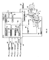
- the motorcycle 1 is mainly controlled by the ECU (electronic control unit) 5 as a control system.
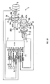
- the ECU 5 includes: a memory 57 storing various settings; a CPU (central processing unit) 50 as a calculating section and a drive circuit 56.
- the CPU 50 has an MT mode temporarily selecting section 51, a change mode selecting section 52, a release signal outputting section 53, an AT mode returning section 54 and a gear ratio control section 55.
- a mode temporarily changing switch 43 a mode selecting switch 44, a shift up switch 41, a shift down switch 42, a throttle opening sensor 33, a brake lever 4c, an engine speed sensor 11, a sheave position detecting sensor 26, a secondary sheave rotational speed sensor 27 and a vehicle speed sensor 32 are connected to the ECU 5.
- the mode temporarily changing switch 43 outputs a mode change signal 101 to the ECU 5 when operated by the rider.
- the mode selecting switch 44 outputs a mode selection signal 102 to the ECU 5 when operated by the rider.
- the throttle opening sensor 33 detects a throttle opening of the motorcycle 1.
- the throttle opening sensor 33 outputs the throttle opening that is detected to the ECU 5 as a throttle opening signal 103.
- the brake lever 4c outputs a brake signal 104 to the ECU 5 when operated by the rider.
- the shift up switch 41 outputs a shift up signal 105 to the ECU 5 when operated by the rider.
- the shift down switch 42 outputs a shift down signal 106 to the ECU 5 when operated by the rider.
- the engine speed sensor 11 detects a rotational speed of the engine 10.
- the engine speed sensor 11 outputs the detected rotational speed of the engine 10 to the ECU 5 as an engine speed signal 109.
- the sheave position detecting sensor 26 is a sensor for detecting a gear ratio of the gear change mechanism 21. More specifically, the sheave position detecting sensor 26 detects a width of the belt groove of the primary sheave 23. For example, if the primary sheave 23 is formed with a fixed sheave body and a movable sheave body movable relative to the fixed sheave body as embodied in this embodiment, the sheave position detecting sensor 26 detects a position of the movable sheave body relative to the fixed sheave body. The sheave position detecting sensor 26 outputs a position of the movable sheave body to the ECU 5 as a sheave position signal 110.
- the secondary sheave rotational speed sensor 27 detects the rotational speed of the secondary sheave 24.
- the secondary sheave rotational speed sensor 27 outputs the detected rotational speed of the secondary sheave 24 to the ECU 5 as a secondary sheave rotational speed signal 111.
- the vehicle speed sensor 32 detects a vehicle speed of the motorcycle 1.
- the vehicle speed sensor 32 outputs the detected vehicle speed to the ECU 5.
- the vehicle speed sensor 32 can be a sensor which detects a rotational speed of the rear wheel 3.
- the vehicle speed sensor 32 can be, for example, another sensor that detects a vehicle speed by detecting a rotational speed of the output shaft of the speed reduction mechanism 31.
- the vehicle speed sensor 32 can be a further sensor which detects a vehicle speed by detecting a rotational speed of the front wheel.
- the ECU 5 controls the engine 10. More specifically, the ECU 5 calculates an engine speed which is a target value based upon the throttle opening signal 103, the vehicle speed signal 112, etc.
- the ECU 5 controls the rotational speed or the like of the engine 10 to be the target engine speed by controlling ignition timing of an ignition system (not shown) of the engine 10, a fuel supply amount to the engine 10 and others while monitoring the engine speed signal 109.
- the ECU 5 controls the transmission 20. More specifically, the ECU 5 calculates a gear ratio which is a target value using the engine speed signal 109, the vehicle speed signal 112, etc. The ECU 5 determines a current gear ratio of the transmission 20 using the sheave position signal 110, etc. The ECU 5 outputs a PWM (pulse-width modulation) signal 108 to the drive circuit 56 based upon the calculated target gear ratio and the determined current gear ratio. The drive circuit 56 applies a pulse voltage to the motor 22 in response to the inputted PWM signal 108. Thereby, the gear ratio of the transmission 20 is controlled to be the target gear ratio.
- PWM pulse-width modulation
- the actuator changing the gear ratio of the transmission 20 can be an electric motor controlled in a manner of PAM (pulse amplitude modulation).
- the actuator changing the gear ratio of the transmission 20 can be a stepper motor.
- the actuator changing the gear ratio of the transmission 20 can be a hydraulic actuator or the like.
- an AT mode, a manual MT mode and an automatic MT mode are selectable. As shown in FIG. 5 , one of the AT mode, the manual MT mode and the automatic MT mode can be selected by the rider's operation of the mode selecting switch 44.
- a mode selection signal 102 is outputted to the ECU 5 from the mode selecting switch 44. More specifically, the mode selection signal 102 is outputted to the gear change mode selecting section 52 of the ECU 5.
- the gear change mode is changed from a current gear change mode as shown in FIG. 5 . For example, if the current gear change mode is the AT mode, the gear change mode is changed to the automatic MT mode by the rider' s operation of the mode selecting switch 44 once.
- the gear change mode is changed to the manual MT mode from the automatic MT mode this time.
- the gear change mode changes to the AT mode, which was selected before, from the manual MT mode. That is, the gear change modes change in turn whenever the mode selecting switch 44 is operated and the mode selection signal 102 is outputted.
- the gear ratio control section 55 controls the gear ratio of the transmission 20 in accordance with the changed gear change mode.
- gear change modes change in turn whenever the mode selecting switch 44 is operated.
- a mode selecting switch for selecting the AT mode and another mode selecting switch for selecting the automatic MT mode, and further another mode selecting switch for selecting the manual MT mode can be separately provided.
- the AT mode is a mode in which the gear ratio of the transmission 20 is continuously and automatically changed by the gear change ratio control section 55 in accordance with running states of the motorcycle 1.
- the "AT mode” is a mode in which the gear ratio of the transmission 20 is automatically changed without steps in accordance with the running states of the motorcycle 1.
- the "AT mode” can be a mode in which the gear ratio of the transmission 20 is continuously and automatically changed based upon a predetermined gear ratio map.
- the memory 57 in the ECU 5 stores a gear ratio map defining relationships between the running states of the motorcycle 1 such as vehicle speed, the engine speed, and the throttle opening of the motorcycle 1, and the gear ratio.
- the gear ratio control section 55 shown in FIG. 4 calculates the target gear ratio based upon the gear ratio map, and the vehicle speed signals 112, the engine speed signals 109, etc.
- the gear ratio control section 55 outputs a PWM signal 108 which is based upon the calculated target gear ratio, the sheave position signal 110 and the secondary sheave rotational speed signal 111 to the drive circuit 56.
- the drive circuit 56 applies a pulse voltage corresponding to the PWM signal 108 to the motor 22. Thereby, the motor 22 is driven and the width of the belt groove of the primary sheave 23 is adjusted. As a result, the gear ratio of the transmission 20 is changed to the target gear ratio.
- the MT mode is a mode in which the gear ratio of the transmission 20 is automatically or manually changed among predetermined multiple gear ratios.
- a mode in which the gear ratio of the transmission 20 is changed by the rider's operation of the operation switches such as the shift up switch 41, the shift down switch 42 or the like is the “manual MT mode.” That is, in the "manual MT mode," the shift changes are made by the rider.
- the "MT mode" can be called a fake MT mode to be distinguished from the normal manual transmission mode in which gear ratios are physically changed among multiple gears.
- five substantially fixed gear ratios i.e., a first speed, a second speed, a third speed, a fourth speed and a fifth speed are set in this order from the lowest speed in this embodiment.
- the respective gear ratios of the first through fifth speeds can be completely fixed.
- the gear ratios can be changed, for example, in accordance with the engine speed.
- the respective gear ratios of the first through fifth speeds can be set in such a manner, for example, that the gear ratio is positioned closer to the top speed as the engine speed becomes higher.
- the gear ratio does not change unless the rider operates the operation switch such as the shift up switch 41, the shift down switch 42 or the like.
- the gear ratio is not automatically changed among the respective gear ratios of the transmission 20 unless the rider operates the operation switch such as the shift up switch 41, the shift down switch 42 or the like.
- the shift down operation can be exceptionally forcibly and automatically made for purposes such as, for example, for avoiding an engine stall under a deceleration condition, or the like, of the motorcycle 1.
- a shift down signal 106 is outputted to the ECU 5 from the shift down switch 42.
- the gear ratio control section 55 of the ECU 5 outputs a PWM signal 108 for changing the gear ratio of the transmission 20 to the fourth speed from the fifth speed to the drive circuit 56.
- the drive circuit 56 applies a pulse voltage corresponding to the PWM signal 108 to the motor 22.
- the gear ratio of the transmission 20 changes to the fourth speed from the fifth speed.
- MT mode a mode in which the gear ratio of the transmission 20 is automatically changed among the predetermined multiple gear ratios by the gear ratio control section 55 without any operations by the rider is defined as the "automatic MT mode.”
- the gear ratios of the transmission 20 are automatically changed in accordance with changes of the running states of the motorcycle 1 without any operations by the rider.
- the gear ratio is not continuously changed, differently from the AT mode.
- the gear ratio is not changed steplessley, unlike the AT mode. That is, in the automatic MT mode, the gear ratio of the transmission 20 is automatically changed among the predetermined gear ratios.
- shift change timing is set to be different in accordance with, for example, the throttle opening or the like. More specifically, if the rider greatly opens the throttle valve (i.e., throttle opening: large) to relatively promptly accelerate the motorcycle, the shift change is made at a relatively high engine speed. On the other hand, if the rider slightly opens the throttle valve (i.e., throttle opening: small) to relatively slowly accelerate the motorcycle, the shift change is made at a relatively low engine speed. In the shift down operation, similarly to the shift up operation, shift change timing is set to be different in accordance with, for example, the throttle opening or the like.
- the MT shift down mode is temporarily selected.
- the gear ratio of the transmission 20 is changed to one of the gear ratios existing in a LOW range which is lower than a current gear ratio of the transmission 20 within the predetermined multiple gear ratios (the first speed through the fifth speed) by the gear ratio control section 55.
- the gear ratio is changed to a gear ratio in a LOW range which is further lower than the current gear ratio of the transmission 20.
- the rider can optionally change the gear ratio of the transmission 20.
- the rider in the AT mode, the rider is not able to optionally change the gear ratio of the transmission 20 because the gear ratio of the transmission 20 is automatically changed.
- the MT shift down mode is the gear change mode that is set under the circumstances so that a kick down operation or activation of engine brake are enabled with the rider's simple operation in the state that the AT mode is selected.
- the gear ratio of the transmission 20 is changed to a gear ratio which is the closest to the current gear ratio of the transmission 20 and exists in a LOW range which is lower than the current gear ratio of the transmission 20 within the predetermined multiple gear ratios (the first speed through the fifth speed).
- the present invention is not limited to the example.
- the gear ratio control section 55 the gear ratio of the transmission 20 can be changed to a gear ratio which is further from the current gear ratio of the transmission 20 than the gear ratio that is the closest to the current gear ratio of the transmission 20 existing in the LOW range that is lower than the current gear ratio of the transmission 20 within the predetermined multiple gear ratios (the first speed through the fifth speed).
- the gear ratio of the transmission 20 can be changed to a gear ratio which is further from the current gear ratio of the transmission 20 by one stage more than the gear ratio that is the closest to the current gear ratio of the transmission 20 existing in the LOW range that is lower than the current gear ratio of the transmission 20 within the predetermined multiple gear ratios (the first speed through the fifth speed). Furthermore, by the gear ratio control section 55, the gear ratio of the transmission 20 can be changed to a gear ratio which is further from the current gear ratio of the transmission 20 by two stages or more, more than the gear ratio that is the closest to the current gear ratio of the transmission 20 existing in the LOW range that is lower than the current gear ratio of the transmission 20 within the predetermined multiple gear ratios (the first speed through the fifth speed).
- the rider can set shift down amounts. For example, if the rider desires to make a relatively quick drive, the rider can select a mode having a large shift down amount. If the rider desires to make a relatively slow drive, the rider can select a mode having a small shift down amount.
- multiple mode temporarily changing switches 43 can be provided. For example, a mode temporarily changing switch 43 whose shift down amount is relatively small and another mode temporarily changing switch 43 whose shift down amount is relatively large can be provided.
- the MT shift down mode will be described in greater detail.
- the MT shift down mode is a manual gear change mode in which the gear ratio of the transmission 20 is changed among the predetermined multiple gear ratios (the first speed through the fifth speed) by the gear ratio control section 55 in response to the rider's operation of the operation switches
- the MT shift down mode can be a gear change mode in which the gear ratio of the transmission 20 is automatically changed among the predetermined multiple gear ratios (the first speed through the fifth speed) by the gear ratio control section 55 in accordance with the running states of the motorcycle 1.
- the MT shift down mode is temporarily selected. More specifically, a mode change signal 101 is outputted to the MT mode temporarily selecting section 51 of the ECU 5.
- the MT mode temporarily selecting section 51 commands the gear change mode selecting section 52 to select the MT shift down mode. Thereby, the MT shift down mode is selected by the gear change mode selecting section 52.
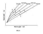
- the gear ratio of the transmission 20 is changed to a gear ratio which is the closest to the current gear ratio of the transmission 20 and exists in a LOW range which is lower than the current gear ratio of the transmission 20 within the predetermined multiple gear ratios (the first speed through the fifth speed). For example, as shown in FIG. 13 , if the mode change signal 101 is outputted at point A positioned between the fifth speed and the fourth speed, the gear ratio is changed to point B representing the fourth speed.
- the gear ratio of the transmission 20 given when the mode temporarily changing switch 43 is operated is consistent with one of the predetermined multiple gear ratios (the first speed through the fifth speed)
- the gear ratio consistent with the current gear ratio of the transmission 20 within the predetermined multiple gear ratios is maintained.
- the shift down operation is not substantially made in the operating time of the mode temporarily changing switch 43.
- the shift down operation is made later by comparing with the AT mode in which the gear ratio is changing toward the shift up range.
- step S2 if it is determined that the mode temporarily changing switch 43 is operated in the MT shift down mode, the shift down operation is made (step S2). For example, if the mode temporarily changing switch 43 is operated at point C of FIG. 13 , a mode change signal 101 is outputted to the ECU 5. When the mode change signal 101 is outputted to the ECU 5, the gear ratio is shifted down to a gear ratio (the third speed, point D) existing in a LOW range which is lower than the current gear ratio (the fourth speed) of the transmission 20 from the current gear ratio by the gear change ratio control section 55.
- a gear ratio the third speed, point D
- the ECU 5 determines whether a predetermined operation is made to the motorcycle 1 and whether a predetermined condition is satisfied in connection with the motorcycle 1. If the ECU 5 determines that the predetermined operation is made to the motorcycle 1 and the predetermined condition is satisfied in connection with the motorcycle 1, a release signal 107, as shown in FIG. 4 , is outputted to the AT mode returning section 54 from the release signal outputting section 53. When the release signal 107 is inputted to the AT mode returning section 54, the AT mode returning section 54 makes the gear change mode selected by the change mode selecting section 52 return to the AT mode.
- the ECU 5 determines that the predetermined operation is not made to the motorcycle 1 and the predetermined condition is not satisfied in connection with the motorcycle 1, the ECU returns to the step S2 to determine whether the mode temporarily changing switch 43 is operated or not. Therefore, if the mode temporarily changing switch 43 is operated in the MT shift down mode, the shift down operation is further made. That is, whenever the mode temporarily changing switch 43 is operated in the MT shift down mode, the shift down operation is made.
- the gear ratio is shifted down to a gear ratio (the second speed, point F) existing in a LOW range which is lower than the current gear ratio (the third speed) from the current gear ratio.
- the gear ratio is shifted down to a gear ratio (the first speed, point H) existing in a LOW range which is lower than the current gear ratio (the second speed) from the current gear ratio.
- predetermined condition and the "predetermined operation” determined at the step S3 are not specifically limited to any ones if they can be used for determining that the rider no longer has an intention for acceleration or no longer has an intension for activation of engine brake, or that such intensions become weaker.
- the gear change mode can return to the AT mode when at least one of the throttle opening, the engine speed and the vehicle speed satisfies a predetermined condition. More specifically, the gear change mode can return to the AT mode when the throttle opening reaches a preset opening or falls below the preset opening or when the throttle opening returns to the opening given when the MT shift down mode was selected. The gear change mode can return to the AT mode if the throttle opening is continuously kept at a constant value during a preset period of time.
- the gear change mode can return to the AT mode when the engine speed reaches a preset rotational speed or exceeds the preset rotational speed. More specifically, the gear change mode can return to the AT mode when the engine speed reaches a revolution limit.
- the gear change mode can return to the AT mode when the vehicle speed reaches a preset speed or exceeds the preset speed.
- the gear change mode can return to the AT mode when a vehicle acceleration value obtained by differentiating the vehicle speed with respect to time reaches a preset vehicle acceleration value or falls below the vehicle acceleration value.
- the gear change mode can return to the AT mode when a preset period of time elapses after the MT shift down mode has been selected by the MT mode temporarily selecting section 51. More specifically, the gear change mode can return to the AT mode when a period of three to 120 seconds elapses after the MT shift down mode has been selected by the MT mode temporarily selecting section 51.
- the gear change mode can return to the AT mode when, in the MT shift down mode, the brake lever is operated by the rider and a brake signal 104 is outputted to the ECU 5 or when the brake signal 104 is released after the brake signal 104 has been outputted to the ECU 5.
- the gear change mode can return to the AT mode when, in the MT shift down mode, the shift up switch 41 is operated by the rider and a shift up signal 105 is outputted to the ECU 5.
- the rider when the rider simply operates the mode temporarily changing switch 43 in the AT mode, the MT shift down mode can be selected. Therefore, the rider can easily and promptly make the shift down operation by means of the simple and only one switch operation, i.e., the rider only operates the mode temporarily changing switch 43 once. The rider thus can easily and promptly make a kick down operation or activation of engine brake.
- the shift down operation can be made.
- at least the following two operations are necessary to shift down the gear ratio of the transmission.
- the shift down operation can be easily and promptly made in the AT mode by means of a single operation such as an operation of the mode temporarily change switch 43.
- a manner for enabling the kick down operation or the activation of engine brake with a simple operation by the rider a manner can be proposed such that, in the AT mode, a kick down mode in which the transmission 20 is controlled using a target gear ratio shifted to a LOW range by a certain amount from the gear ratio calculated out from the gear change map is set.
- This manner can make the kick down operation only by an operation of a switch for shifting to the kick down mode.
- the kick down mode is the AT mode eventually.
- a brisk kick down operation having a direct sense or a deceleration whose engine brake effect is large is required, such a kick down operation has difficulty to sufficiently meet the requirement.
- the mode changes to the MT shift down mode when the mode temporarily changing switch 43 is operated. Then, the shift down operation is made in the MT mode. Therefore, according to this embodiment, the brisk kick down operation having a fixed gear change sense and the direct sense or the deceleration by engine brake can be made.
- the mode automatically returns to the AT mode from the MT shift down mode when the predetermined operation is made to the motorcycle 1 and when the predetermined condition is satisfied in connection with the motorcycle 1. That is, in this embodiment, in the AT mode, the temporal shift down operation in the MT mode can be made by the operation that can be made easily and promptly. Therefore, acceleration for overtaking another vehicle or performing a similar operation while running in the AT mode and deceleration for activating engine brake can be very easily made.
- the mode can return to the AT mode without any specific operation being made by the rider, if it is set that the mode returns to the AT mode when at least one of the throttle opening, the engine speed and the vehicle speed satisfies the predetermined condition as shown in FIG. 9 , or if it is set that the mode returns to the AT mode when the preset period of time elapses after the MT shift down mode has been selected by the MT mode temporarily selecting section 51 as shown in FIG. 10 . Therefore, the return to the AT mode can be especially easily made. Also, in this case, the mode surely return to the AT mode because no specific operation is necessary for returning to the AT mode. That is, omission regarding the return to the AT mode due to the rider's carelessness or the like can be avoided.
- the MT shift down mode continues unless the intension of the rider to make the shift down disappears, while the mode surely returns to the AT mode when the rider desires to return to the AT mode. That is, the intension of the rider can be more accurately reflected.
- the mode is further shifted down.
- a further shift down operation is practicable if, for example, the rider judges that the shift down amount is insufficient only by putting the mode into the MT shift down mode. That is, the rider can more freely operate the motorcycle 1.
- the further shift down operation can be made by the rider's operation of the shift down switch 42 in the MT shift down mode.
- the gear ratio of the transmission 20 can be shifted up when the shift up switch 41 is operated in the MT shift down mode.
- the various switches such as the mode temporarily changing switch 43 are push type switches. The rider thus can easily operate the operation switches.
- each operation switch is formed with a button type switch in this embodiment, the operation switch can be a lever type switch, or the like.
- the various switches such as the mode temporarily changing switch 43 are operable by the rider's thumb 60a.
- the rider's thumb 60a is, comparatively, relatively freely movable rather than the other fingers in the steering operation of the motorcycle 1. Therefore, the operability of the various switches such as the mode temporarily changing switch 43 is enhanced.
- the thumb can be more easily moved than the other fingers when the rider grasps the brake lever 4c. Simultaneous operations of the brake and the various switches thus can be relatively easily made.
- the various switches such as the mode temporarily changing switch 43 are disposed in the left grip section 4a on the opposite side to the right grip section 4b where the rider operates the throttling member. Therefore, the rider can relatively easily operate the operation switches while simultaneously operating the throttling member.
- the two kinds of MT modes i.e., the manual MT mode and the automatic MT mode are selectable.
- the rider thus can make the shift change at his or her will by selecting the manual MT mode.
- the rider if the rider prefers the shift change that has a higher direct sense and more MT taste but does not prefer making the shift change, the rider can select the automatic MT mode to automatically make the fake MT shift change.
- the further shift down operation is made following the operation of the mode temporarily changing switch 43 in the MT shift down mode.
- the further shift down operation can be made following an operation of the shift down switch 42 by the rider and the mode can return to the AT mode following the operation of the mode temporarily changing switch 43 in the MT shift down mode.
- the mode temporarily changing switch 43 is separately provided and the mode changes to the MT shift down mode following the operation of the mode temporarily changing switch 43 is described.
- the present invention is not limited to the construction.
- the mode temporarily changing switch 43 is not separately provided and the mode changes to the MT shift down mode following the operation of the shift down switch 42 will be described.
- FIG. 1 is referred in common with the above embodiment. Also, the same components are assigned with the same numerals and/or symbols and further descriptions are omitted.
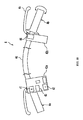
- FIG. 15 is a schematic structural view of a steering handle 4 portion in this variation 2.
- the switch box 40a in this second variation does not have the mode temporarily changing switch 43.
- the left side of the switch box 40a only has the shift up switch 41 and the shift down switch 42. Because the number of switches disposed in the left side portion of the switch box 40a is relatively few, the shift up switch 41 and the shift down switch 42 are larger than those provided in the above embodiment.
- the place for the mode selecting switch 44 is not limited to the left grip section 4a.
- the mode selecting switch 44 can be placed in the left side portion of the right grip section 4b.
- a further switch box can be disposed in the left side portion of the right grip section 4b and the mode selecting switch 44 can be positioned in the further switch box.
- the mode selecting switch 44 is positioned at a location where the fore finger of the right hand of the rider can operate the switch 44.
- the shift down signal 106 outputted when the shift down switch 42 is operated in the AT mode is the mode change signal 101. That is, as shown in FIG. 17 , when the shift down switch 42 is operated by the rider at a step S1(b) in the AT mode, the shift down signal 106 functioning as the mode change signal 101 is outputted to the ECU 5.
- the shift down signal 106 is inputted to the ECU 5
- the MT shift down mode is selected by the MT mode temporarily selecting section 51.
- the gear ratio of the transmission 20 is changed to one of the gear ratios existing in a LOW range which is lower than a current gear ratio of the transmission 20 within the predetermined multiple gear ratios (the first speed through the fifth speed) by the gear ratio control section 55.
- step S2(b) when the shift down switch 42 is operated in the MT shift down mode, the shift down operation is made (step S2(b)).
- the mode temporarily changing switch 43 is not necessary to be provided and, to the extent of the size thereof, the shift up switch 41 and the shift down switch 42 can be upsized. Thereby, the operability for the rider is enhanced. Also, because the number of the operation switches decreases, the rider can more easily operate them.
- the mode selecting switch 44 is placed in the switch box 40a disposed in the left grip section 4a disposed in the left grip section 4a .
- the place for the mode selecting switch 44 is not limited to the left grip section 4a.
- the mode selecting switch 44 can be placed in the left side portion of the right grip section 4b.
- a further switch box 40b can be disposed in the left side portion of the right grip section 4b and the mode selecting switch 44 can be positioned in the further switch box.
- the mode selecting switch 44 is positioned at a location where the rider can operate the switch with the forefinger of the right hand.
- the electronically controlled transmission can be an ECVT other than the belt type.
- the electronically controlled transmission can be a toroidal type ECVT.
- the straddle type vehicle in accordance with the present invention can include motorcycles such as, for example, the so-called motorcycle, a moped and an off-road vehicle. Also, the straddle type vehicle can be an ATV (all terrain vehicle) or the like.
- the example in which the various operation switches such as the shift up switch 41, the shift down switch 42, the mode temporarily changing switch 43 and the mode selecting switch 44 are formed with push type and so-called button type switches.
- the various operation switches can be formed with push type levers.
- the various operation switches can be rotary type switches whose knobs are moved among multiple positions.
- the example is described in which, by the gear ratio control section 55, the gear ratio of the transmission 20 is changed to a gear ratio which is the closest to the current gear ratio of the transmission 20 and exists in a LOW range which is lower than the current gear ratio of the transmission 20 within the predetermined multiple gear ratios (the first speed through the fifth speed).
- the present invention is not limited to the example.
- the gear ratio control section 55 the gear ratio of the transmission 20 can be changed to a gear ratio which is further closer to the current gear ratio of the transmission 20 more than the gear ratio that is the closest to the current gear ratio of the transmission 20 existing in the LOW range that is lower than the current gear ratio of the transmission 20 within the predetermined multiple gear ratios (the first speed through the fifth speed).
- the gear ratio of the transmission 20 can be changed to a gear ratio which is further closer to the current gear ratio of the transmission 20 by one stage more than the gear ratio that is the closest to the current gear ratio of the transmission 20 existing in the LOW range that is lower than the current gear ratio of the transmission 20 within the predetermined multiple gear ratios (the first speed through the fifth speed). Furthermore, by the gear ratio control section 55, the gear ratio of the transmission 20 can be changed to a gear ratio which is further closer to the current gear ratio of the transmission 20 by two stages or more, more than the gear ratio that is the closest to the current gear ratio of the transmission 20 existing in the LOW range that is lower than the current gear ratio of the transmission 20 within the predetermined multiple gear ratios (the first speed through the fifth speed).
- the rider can set shift down amounts. For example, if the rider desires to make a relatively quick drive, the rider can select a mode having a large shift down amount. If the rider desires to make a relatively slow drive, the rider can select a mode having a small shift down amount.
- multiple mode temporarily changing switches 43 can be provided. For example, a mode temporarily changing switch 43 whose shift down amount is relatively small and another mode temporarily changing switch 43 whose shift down amount is relatively large can be provided.
- the actuator changing the gear ratio of the transmission 20 can be an electric motor controlled in a manner of PAM (pulse amplitude modulation).
- the actuator changing the gear ratio of the transmission 20 can be a stepper motor.
- the actuator changing the gear ratio of the transmission 20 can be a hydraulic actuator or the like.
- both of the automatic MT mode and the manual MT mode are selectable.
- a setting in which either one of the automatic MT mode and the manual mode is selectable is applicable.
- another setting in which both of the automatic MT mode and the manual MT mode are not selectable is applicable. That is, a construction in which only the AT mode and the MT shift down mode are selectable without having the mode selecting switch 44 is applicable.
- a setting in which gear change modes other than the AT mode, the automatic MT mode, the manual MT mode and the MT shift down mode are selectable is applicable.
- the mode can change to the automatic MT mode in the MT shift down mode. That is, a setting is applicable in which the gear ratio of the transmission 20 is automatically changed, after the mode changes to the MT shift down mode, in accordance with the running states of the motorcycle 1 without the rider's operation of the operation switch.
- the transmission 260 having a metal V belt may be used instead of the transmission 20 of the first embodiment.
- the members or sections that perform the same operation as in the transmission of the embodiment described in FIG. 4 are indicated by the same reference numerals.
- the internal constitution of the ECU 5 is same as the first embodiment, and is therefore not shown in the drawings.
- transmission 260 is applied with several modifications in addition to the V belt 264 made of metal as shown in FIG. 19 (occasionally referred as "metal belt” hereafter).
- the metal belt CVT 260 includes a clutch 35, a primary rotation sensor 261, a hydraulic cylinder 267A, 267B, and a hydraulic control valve 267C.
- the clutch 35 is provided between the output shaft 12 of the engine 10 and the input shaft 13 of the metal belt CVT 260.
- the clutch 35 engages or disengages the power transmission between the output shaft 12 of the engine 10 and the input shaft 13 of the metal belt CVT 260.
- the clutch 35 of the embodiment is an electronically controlled multiplate clutch. Therefore, the engagement or disengagement of the clutch 35 is electronically controlled automatically.
- the driving force of the engine 10 is transmitted to the primary sheave 23 through the clutch 35 when the clutch 35 is engaged.
- the driving force transmitted to the primary sheave 23 is transmitted to the secondary sheave 24 through the belt 264.
- the primary rotational speed sensor 261 detects the rotational speed of the primary sheave 23.
- the primary rotational speed sensor 261 outputs the detected rotational speed of the primary sheave 23 to the ECU 5 as a sheave rotational speed signal 114.
- the primary sheave 23 and the secondary sheave 24 have a movable sheave half 23a and 24a, and fixed sheave half 23b, 24b respectively.
- the movable sheave half 23b is constituted so as to in the axial direction of the input shaft 13 of the metal belt 260.
- the movable sheave half 24b is constituted so allowed moving in the axial direction of the output shaft 14 of the metal belt CVT 260.
- the primary rotation sensor 261 detects the rotational speed of the primary sheave 23.
- the ECU 5 calculates the gear ratio of the metal belt CVT 260 from the ratio between the rotational speed of the primary sheave 23 detected by the primary rotation sensor 261 and the vehicle speed of the straddle type vehicle detected by the vehicle speed sensor 32.
- the gear ratio of the metal belt CVT 260 is calculated at the ECU 5 by the ratio of the sheave rotational speed signal 114 to the vehicle speed signal 112.
- the gear ratio of the metal belt CVT 260 may be calculated from the ratio between the rotational speed of the primary sheave 23 detected by the primary rotational sensor 261 and the rotational speed of the secondary sheave 24 detected by the secondary sheave rotational speed sensor 27. That is, the gear ratio of the metal belt CVT 260 may be calculated at the ECU 5 from the ratio of the sheave rotational speed signal 114 to the secondary sheave rotational speed signal 111.
- the hydraulic cylinder 267A controls the groove width of the primary sheave 23.
- the hydraulic cylinder 267A controls the groove width of the primary sheave 23, by applying a pressure to the movable sheave half 23b constituting the primary sheave 23.
- the hydraulic cylinder 267B controls the groove width of the secondary sheave 24.
- the hydraulic cylinder 267B controls the groove width of the secondary sheave 24, by applying a pressure to the movable sheave half 24b constituting the secondary sheave 24.
- the hydraulic control valve 267C is a valve that controls the hydraulic pressures applied to the hydraulic cylinders 267A, 267B.
- the hydraulic control valve 267C controls the hydraulic pressures so that when the hydraulic pressure of one of the hydraulic cylinders 267A and 267B is set higher, and the hydraulic pressure of the other of the hydraulic cylinders 267B and 267A is set lower respectively.
- the hydraulic control valve 267C is controlled by the ECU 5.
- the gear ratio of the metal belt CVT 260 is changed by control of the hydraulic control valve 267C at the ECU 5.
- the control of the ECU 5 is performed in the same way as in the first embodiment.
- the ECU 5 may set the rotational speed of the primary sheave 23 instead of the engine speed as a control target value.
- driving source refers to a device that generates power.
- the “driving source” may be, for example, an internal combustion engine, an electric motor or the like.
- the term "electronically controlled transmission” means transmission in general whose gear ratio is changed by using electric power.
- the "electronically controlled transmission” includes a transmission whose gear ratio is changed by an electric motor and a transmission whose gear ratio is changed by an electronically controlled hydraulic actuator. That is, insofar as it is electronically controlled, types of the actuator for changing the gear ratio are not specifically limited.
- the "push type switch” includes, for example, a lever type push type switch and a button type switch.
- the "motorcycle” includes not only a motorcycle in a narrow sense but also, for example, a scooter and a so-called moped.
- the present invention is useful for vehicles having the ECVT.
Landscapes
- Engineering & Computer Science (AREA)
- General Engineering & Computer Science (AREA)
- Mechanical Engineering (AREA)
- Control Of Transmission Device (AREA)
Abstract
Description
- The present invention relates to a control and a transmission of a straddle type vehicle, a transmission, and also relates to the straddle type vehicle.
- Electronically controlled continuously variable transmissions (referred to as "ECVT" hereafter) are known. In a conventional ECVT, the gear ratio is automatically changed based upon a gear ratio map indicative of relationships among vehicle speeds, engine speeds (accelerator openings) and gear ratios. Accordingly, vehicles incorporating an ECVT (hereunder, called "vehicle incorporating the ECVT") do not require any gear change operations or clutch operations by a rider. Therefore, recently, the ECVT is incorporated in various vehicles.
- The rider, however, cannot change the gear ratios optionally out of the setting given in the gear ratio map, with the vehicle incorporating the ECVT. Hence, the rider has difficulty in effectively activating engine braking at will with the vehicle incorporating the ECVT. More specifically, it is difficult for the rider to activate the engine brake more strongly than that given by the gear ratio map.
- Also, with the vehicle incorporating the ECVT, it is difficult to make a so-called kick down operation whereby, when a vehicle passes or overtakes another vehicle, a shift down operation is intentionally made more greatly than in a normal state to increase acceleration of the vehicle.
- Under the circumstances, a vehicle incorporating the ECVT is proposed whereby both of the so-called automatic transmission (AT) mode in which the gear ratios can be continuously and automatically changed and the so-called manual transmission (MT) mode in which the gear ratios can be changed optionally by the rider are selectable. More specifically,
JP-A-04-131588 JP-A-62-175228 - However, the conventional vehicle incorporating the ECVT that is changeable between the AT mode and the MT mode requires complicated and troublesome operations when the shift down operation is intentionally made in the AT mode to accelerate or decelerate the vehicle. Specifically, in the AT mode, at least the following three operations are necessary for increase or decrease the vehicle speed by shifting down intentionally.
- 1. The switching operation from the AT mode to the MT mode.
- 2. The shift down operation in the MT mode.
- 3. The switching operation from the MT mode to the AT mode.
- The present invention is made in view of the above points and aims to make it practicable that an intentional shift down operation is easily made in the AT mode.
- According to an aspect of the present invention, there is provided a control system adapted for use with an electronically controlled continuously variable transmission located between a driving source and a driving wheel of a vehicle, said control system comprising:
- a gear ratio control section for controlling a gear ratio of the transmission;
- a gear change mode selecting section for selecting one of a plurality of gear change modes, including an automatic transmission (AT) mode in which the gear ratio control section changes the gear ratio of the transmission continuously and a manual transmission (MT) mode in which the gear ratio control section changes the gear ratio of the transmission among a plurality of predetermined gear ratios;
- a mode temporarily changing switch for outputting a mode change signal;
- an MT mode temporarily selecting section for:
- temporarily making the gear change mode selecting section select the MT mode temporarily when the mode change signal is inputted in the AT mode selected by the gear change mode selecting section; and
- making the gear ratio control section change a gear ratio of the transmission to one of the plurality of the predetermined gear ratios which is lower than a current gear ratio;
- a release signal outputting section for outputting a release signal when at least one of a predetermined vehicle operation is made and a predetermined condition is satisfied in connection with the vehicle; and
- an AT mode returning section for returning the gear change mode selected by the gear change mode selecting section to the AT mode when the release signal is outputted after the MT mode is temporarily selected by the MT mode temporarily selecting section.
- The MT mode may include an automatic MT mode in which the gear ratio control section automatically changes a gear ratio of the transmission among the plurality of predetermined gear ratios in accordance with a driving state of the straddle type vehicle. The MT mode may include a manual MT mode in which the gear ratio control section changes a gear ratio of the transmission among the plurality of predetermined gear ratios in accordance with an operation of a rider of the straddle type vehicle.
- The control system may further comprise:
- a throttle opening sensor for detecting a throttle opening;
- a rotational speed sensor for detecting a rotational speed of a driving source of an associated vehicle, and
- a vehicle speed sensor for detecting a vehicle speed of the associated vehicle,
- The release signal outputting section may output a release signal when a predetermined period elapses after the MT mode is temporarily selected by the MT mode temporarily selecting section.
- The release signal outputting section may output a release signal when a brake of an associated vehicle is operated.
- The control system may further comprise:
- a shift up switch for shifting up the transmission when the gear change mode selecting section selects the MT mode,
- and the release signal outputting section outputs the release signal when the shift up switch is operated during a period in which the MT mode is temporarily selected by the MT mode temporarily selecting section.
- The release signal outputting section may output a release signal when the mode change signal is outputted after the MT mode is temporarily selected by the MT mode temporarily selecting section.
- The control system may further comprise a shift down switch for outputting a shift down signal.
- The gear ratio control section may change the gear ratio of the transmission to one of the plurality of predetermined gear ratios which is lower than the current gear ratio, when the mode change signal is outputted during a period in which the MT mode is temporarily selected by the MT mode temporarily selecting section.
- The mode temporarily changing switch may comprise a push type switch which outputs the mode change signal when the switch is activated.
- The shift down switch may be adapted to shift down the transmission when the gear change mode selecting section selects the MT mode. The shift down switch and the mode temporarily changing switch may be comprised in a single switch.
- The control system may further comprise a mode selecting switch for outputting a mode selecting signal, whereby the gear change mode selecting section selects one of the plurality of gear change modes.
- According to another aspect of the present invention there is provided a transmission comprising:
- a continuously variable electronically controlled gear change mechanism adapted to be disposed between a driving source and a driving wheel of a vehicle;
- a control system for controlling the gear change mechanism, wherein the control system comprises:
- a gear ratio control section for controlling the gear ratio of the gear change mechanism;
- a gear change mode selecting section for selecting one of a plurality of gear change modes, including an automatic transmission (AT) mode in which the gear ratio control section changes the gear ratio of the gear change mechanism continuously and a manual transmission (MT) mode in which the gear ratio control section changes the gear ratio of the transmission among a plurality of predetermined gear ratios;
- a mode temporarily changing switch for outputting a mode change signal;
- an MT mode temporarily selecting section for:
- temporarily making the gear change mode selecting section select the MT mode temporarily when the mode change signal is inputted in the AT mode selected by the gear change mode selecting section; and
- making the gear ratio control section change a gear ratio of the transmission to one of the plurality of predetermined gear ratios which is lower than a current gear change ratio;
- a release signal outputting section for outputting a release signal when at least one of a predetermined vehicle operation is made and a predetermined condition is satisfied in connection with the vehicle; and
- an AT mode returning section for returning the gear change mode selected by the gear change mode selecting section to the AT mode when the release signal is outputted after the MT mode is temporarily selected by the MT mode temporarily selecting section.
- According to a further aspect of the present invention there is provided vehicle comprising:
- a driving source;
- a driving wheel driven by the driving source;
- a transmission located between the driving source and the driving wheel and including a continuously variable electrically controlled gear change mechanism;
- a control system for controlling the gear change mechanism, wherein the control system comprises:
- a gear ratio control section for controlling the gear ratio of the gear change mechanism;
- a gear change mode selecting section for selecting one of a plurality gear change modes, including an automatic transmission (AT) mode in which the gear ratio control section changes the gear ratio of the gear change mechanism continuously and a manual transmission (MT) mode in which the gear ratio control section changes the gear ratio of the gear change mechanism among a plurality of predetermined gear ratios;
- a mode temporarily changing switch for outputting a mode change signal;
- an MT mode temporarily selecting section for:
- temporarily making the gear change mode selecting section select the MT mode temporarily when the mode change signal is inputted in the AT mode selected by the gear change mode selecting section; and
- making the gear ratio control section change a gear ratio of the gear change mechanism to one of the plurality of predetermined gear ratios which is lower than the current gear ratio; and
- a release signal outputting section for outputting a release signal when at least one of a predetermined vehicle operation is made and when a predetermined condition is satisfied in connection with the vehicle; and
- an AT mode returning section for returning the gear change mode selected by the gear change mode selecting section to the AT mode when the release signal is outputted after the MT mode is temporarily selected by the MT mode temporarily selecting section.
- The mode temporarily changing switch may be located where a rider can operate the switch by their thumb.
- The vehicle may further comprise handlebars including a right grip and a left grip for a rider to hold, wherein the mode temporarily changing switch is located on a right side of the left grip.
- The vehicle may comprise a straddle type vehicle.
- According to another aspect of the present invention there is provided a control system for an electronically controlled transmission disposed between a drive source and a drive wheel of a straddle type vehicle and being capable of continuously changing a gear ratio. The straddle type vehicle has a mode temporarily changing switch. The mode temporarily changing switch outputs a mode change signal to the control system. The control system in accordance with the present invention includes a gear ratio control section, a gear change mode selecting section, a release signal outputting section, an MT mode temporarily selecting section and an AT mode returning section. The gear ratio control section controls the gear ratio of the transmission. The gear change mode selecting section selects one of a plurality of gear change modes. The plurality of gear change modes include an AT mode and an MT mode. In the AT mode, the gear ratio control section continuously changes the gear ratio of the transmission in accordance with a running state of the straddle type vehicle. In the MT mode, the gear ratio control section changes the gear ratio of the transmission among predetermined multiple gear ratios. The release signal outputting section outputs a release signal when a predetermined operation is made to the straddle type vehicle and when a predetermined condition is satisfied in connection with the straddle type vehicle. The MT mode temporarily selecting section makes the gear change mode selecting section temporarily select the MT mode when the mode change signal is inputted under a condition that the AT mode is selected by the gear change mode selecting section. The MT mode temporarily selecting section also makes the gear ratio control section change the gear ratio of the transmission to one of gear ratios existing in a LOW range which is lower than a current gear ratio of the transmission within the predetermined multiple gear ratios. The AT mode returning section returns the gear change mode selected by the gear change mode selecting section to the AT mode when the release signal is outputted after the MT mode is temporarily selected by the MT mode temporarily selecting section.
- According to a yet further aspect of the present invention there is provided a transmission having an electronically controlled gear change mechanism and a control system for controlling the gear change mechanism. The electronically controlled gear change mechanism is disposed between a drive source and a drive wheel of a straddle type vehicle, and being capable of continuously changing a gear ratio. The control system controls the gear change mechanism. The straddle type vehicle has a mode temporarily changing switch. The mode temporarily changing switch outputs a mode change signal to the control system. The control system includes a gear ratio control section, a gear change mode selecting section, a release signal outputting section, an MT mode temporarily selecting section and AT mode returning section. The gear ratio control section controls the gear ratio of the gear change mechanism. The gear change mode selecting section selects one of a plurality of gear change modes. The plurality of gear change modes include an AT mode and an MT mode. In the AT mode, the gear ratio control section continuously changes the gear ratio of the gear change mechanism in accordance with a running state of the straddle type vehicle. In the MT mode, the gear ratio control section changes the gear ratio of the gear change mechanism among predetermined multiple gear ratios. The release signal outputting section outputs a release signal when a predetermined operation is made to the straddle type vehicle and when a predetermined condition is satisfied in connection with the straddle type vehicle. The MT mode temporarily selecting section makes the gear change mode selecting section temporarily select the MT mode when the mode change signal is inputted under a condition that the AT mode is selected by the gear change mode selecting section. The MT mode temporarily selecting section also makes the gear ratio control section change the gear ratio of the gear change mechanism to one of gear ratios existing in a LOW range which is lower than a current gear ratio of the gear change mechanism within the predetermined multiple gear ratios. The AT mode returning section returns the gear change mode selected by the gear change mode selecting section to the AT mode when the release signal is outputted after the MT mode is temporarily selected by the MT mode temporarily selecting section.
- According to another aspect of the present invention there is provided a straddle type vehicle which includes a drive source, a drive wheel and a transmission. The drive wheel is driven by the drive source. The transmission has an electronically controlled gear change mechanism and a control system. The gear change mechanism is disposed between the drive source and the drive wheel and is capable of continuously changing a gear ratio. The control system controls the gear change mechanism. The straddle type vehicle in accordance with the present invention includes a mode temporarily changing switch. The mode temporarily changing switch outputs a mode change signal to the control system. The control system includes a gear ratio control section, a gear change mode selecting section, a release signal outputting section, an MT mode temporarily selecting section and AT mode returning section. The gear ratio control section controls the gear ratio of the gear change mechanism. The gear change mode selecting section selects one of a plurality of gear change modes. The plurality of gear change modes include an AT mode and an MT mode. In the AT mode, the gear ratio control section continuously changes the gear ratio of the gear change mechanism in accordance with a running state of the straddle type vehicle. In the MT mode, the gear ratio control section changes the gear ratio of the gear change mechanism among predetermined multiple gear ratios. The release signal outputting section outputs a release signal when a predetermined operation is made to the straddle type vehicle and when a predetermined condition is satisfied in connection with the straddle type vehicle. The MT mode temporarily selecting section makes the gear change mode selecting section temporarily select the MT mode when the mode change signal is inputted under a condition that the AT mode is selected by the gear change mode selecting section. The MT mode temporarily selecting section also makes the gear ratio control section change the gear ratio of the gear change mechanism to one of gear ratios existing in a LOW range which is lower than a current gear ratio of the gear change mechanism within the predetermined multiple gear ratios. The AT mode returning section returns the gear change mode selected by the gear change mode selecting section to the AT mode when the release signal is outputted after the MT mode is temporarily selected by the MT mode temporarily selecting section.
- According to the present invention, an intentional shift down operation can be easily made in the AT mode.
- These and other aspects of the present invention will now be described, by way of example only, with reference to the accompanying drawings, in which:
-
FIG. 1 is a side view of a two-wheeled motorized vehicle embodying the present invention; -
FIG. 2 is a schematic structural view of a steering handle portion of the vehicle ofFIG. 1 ; -
FIG. 3 is an enlarged schematic structural view of a left grip portion of the steering handle; -
FIG. 4 is a block diagram of a control system; -
FIG. 5 is a conceptual illustration showing gear change modes; -
FIG. 6 is a V-N line graph exemplarily shown for depicting shift changes in a manual MT mode; -
FIG. 7 is a V-N line graph exemplarily shown for depicting shift changes in an automatic MT mode; -
FIG. 8 is a general flowchart for a MT shift down mode; -
FIG. 9 is a flowchart showing a specific first example of the MT shift down mode; -
FIG. 10 is a flowchart showing a specific second example of the MT shift down mode; -
FIG. 11 is a flowchart showing a specific third example of the MT shift down mode; -
FIG. 12 is a flowchart showing a specific fourth example of the MT shift down mode; -
FIG. 13 is a V-N line graph in the MT shift down mode; -
FIG. 14 is a flowchart for the MT shift down mode in a first variation; -
FIG. 15 is a schematic structural view of a steering handle in a second variation; -
FIG. 16 is a block diagram of a control system in the second variation; -
FIG. 17 is a flowchart for the MT shift down mode in the second variation; -
FIG. 18 is a schematic structural view of a steering handle in a third variation; and -
FIG. 19 is a block diagram of a control system in accordance with a second embodiment of the present invention. - In this first embodiment, an example of the present invention is described by providing a
motorcycle 1 in the form of a so-called scooter type. As shown inFIG. 1 , themotorcycle 1 has a steering handle 4, apower unit 2 and arear wheel 3 functioning as a drive wheel. Thepower unit 2 and therear wheel 3 are connected to each other through a power transmission mechanism 6. -
FIG. 2 is a schematic structural view of the steering handle 4. The steering handle 4 has ahandle bar 4d coupled with a steering head pipe which is not shown. The steering handle 4 includes aleft grip section 4a positioned at the left end of thehandle bar 4d and aright grip section 4b positioned at the right end of thehandle bar 4d. Theright grip section 4b is pivotable relative to thehandle bar 4d. When a rider pivots theright grip section 4b, a throttle valve which is not shown is operated to control a throttle opening. - Brake levers 4c are disposed adjacent to the
respective grip sections motorcycle 1 are actuated and, as described later, abrake signal 104 is outputted to anECU 5. - A
switch box 40a is disposed in a right side portion of theleft grip section 4a. Theswitch box 40a has various operation switches such as, for example, a shift upswitch 41, a shift downswitch 42, a mode temporarily changingswitch 43 and amode selecting switch 44. - As shown in
FIG. 3 , the various operation switches such as the shift upswitch 41, the shift downswitch 42, the mode temporarily changingswitch 43 and themode selecting switch 44 are positioned at locations where thethumb 60a of theleft hand 60 of the rider can operate them. More specifically, the various operation switches are arranged in a top surface slightly inclining downward toward a rear portion of theswitch box 40a. That is, the various operation switches are arranged in a surface of theswitch box 40a facing the rider. - The present invention, however, is not limited to this structure. For example, some of the operation switches such as, for example, the shift up
switch 41 can be arranged in a rear surface of theswitch box 40a in the view from the rider' s position so that those switches are operable by the forefinger. For example, it is applicable that the shift upswitch 41 is arranged in the rear surface in the view from the rider's position while the shift downswitch 42 is arranged in the surface facing the rider. In other words, it is applicable that the shift upswitch 41 is operable by the forefinger while the shift downswitch 42 is operable by thethumb 60a. Also, all of the operation switches can be arranged in the rear surface of theswitch box 40a in the view from the rider's position to be operable by the forefinger. - In this embodiment, the various operation switches such as the shift up
switch 41, the shift downswitch 42, the mode temporarily changingswitch 43 and themode selecting switch 44 are formed with push type and so-called button type switches. However, the various operation switches can be formed with push type levers. Also, the various operation switches can be rotary type switches whose knobs are moved among multiple positions. - As shown in
FIG. 3 , the shift upswitch 41, the shift downswitch 42 and the mode temporarily changingswitch 43 in the various operation switches are placed at positions closest to theleft hand 60 of the rider. In other words, the shift upswitch 41, the shift downswitch 42 and the mode temporarily changingswitch 43 are placed at outermost positions in the vehicle width direction. The mode temporarily changingswitch 43 is positioned between the shift upswitch 41 and the shift downswitch 42. Themode selecting switch 44 is placed at a position spaced apart from theleft hand 60 more than the shift upswitch 41, the shift downswitch 42 and the mode temporarily changingswitch 43. This is because frequency in use of themode selecting switch 44 is lower than those of the shift upswitch 41, the shift downswitch 42 and the mode temporarily changingswitch 43. As thus described, it is preferable that the shift upswitch 41, the shift downswitch 42 and the mode temporarily changingswitch 43 whose frequency in use is high are placed at the positions closer to theleft hand 60 where the switches can be relatively easily operated. - Additionally, the place for the
mode selecting switch 44 is not limited to theleft grip section 4a. For example, themode selecting switch 44 can be placed in the left side portion of theright grip section 4b. More specifically, a further switch box can be disposed in the left side portion of theright grip section 4b and themode selecting switch 44 can be positioned in the further switch box. In this alternative arrangement, it is preferable that themode selecting switch 44 is positioned at a location where the fore finger of the right hand of the rider can operate theswitch 44. - As shown in
FIG. 4 , anengine 10 functioning as a drive source, an electronically controlledtransmission 20, a centrifugal clutch 30 and aspeed reduction mechanism 31 are provided. Thetransmission 20 has agear change mechanism 21 and anelectric motor 22 functioning as an actuator. Themotor 22 is used for changing a gear ratio of thegear change mechanism 21. - The
gear change mechanism 21 has aprimary sheave 23 and asecondary sheave 24. Theprimary sheave 23 is mounted to anoutput shaft 12 of theengine 10 and rotates together with the rotation of theoutput shaft 12. Abelt 25 whose cross section generally has a V-shape is wound around theprimary sheave 23 and thesecondary sheave 24. Themotor 22 is attached to theprimary sheave 23. A width of a belt groove of theprimary sheave 23 around which thebelt 25 is wound is changed by themotor 22. Thereby, the gear ratio of thegear change mechanism 21 can be continuously changed. More specifically, the gear ratio of thegear change mechanism 21 can be steplessly changed. - The
secondary sheave 24 is connected to thespeed reduction mechanism 31 through thecentrifugal clutch 30. Thespeed reduction mechanism 31 is connected to therear wheel 3 through the power transmission mechanism 6 formed with a belt, a chain, a drive shaft, etc. - The centrifugal clutch 30 is connected or disconnected in accordance with a rotational speed of the
secondary sheave 24. More specifically, the centrifugal clutch 30 is under the disconnected condition if the rotational speed of thesecondary sheave 24 is less than a predetermined rotational speed. Therefore, the rotation of thesecondary sheave 24 is not transmitted to therear wheel 3. On the other hand, the centrifugal clutch 30 is under the connected condition if the rotational speed of thesecondary sheave 24 is equal to or greater than the predetermined rotational speed. Therefore, the rotation of thesecondary sheave 24 is transmitted to therear wheel 3 through the centrifugal clutch 30, thespeed reduction mechanism 31 and the power transmission mechanism 6. Thereby, therear wheel 3 is rotated. - A control block of the
motorcycle 1 will now be described with reference toFIG. 4 . As shown inFIG. 4 , themotorcycle 1 is mainly controlled by the ECU (electronic control unit) 5 as a control system. TheECU 5 includes: amemory 57 storing various settings; a CPU (central processing unit) 50 as a calculating section and adrive circuit 56. TheCPU 50 has an MT mode temporarily selectingsection 51, a changemode selecting section 52, a releasesignal outputting section 53, an ATmode returning section 54 and a gearratio control section 55. - Various sensors and switches or the like are connected to the
ECU 5. More specifically, a mode temporarily changingswitch 43, amode selecting switch 44, a shift upswitch 41, a shift downswitch 42, athrottle opening sensor 33, abrake lever 4c, anengine speed sensor 11, a sheave position detecting sensor 26, a secondary sheaverotational speed sensor 27 and avehicle speed sensor 32 are connected to theECU 5. - The mode temporarily changing
switch 43 outputs amode change signal 101 to theECU 5 when operated by the rider. Themode selecting switch 44 outputs amode selection signal 102 to theECU 5 when operated by the rider. Thethrottle opening sensor 33 detects a throttle opening of themotorcycle 1. Thethrottle opening sensor 33 outputs the throttle opening that is detected to theECU 5 as athrottle opening signal 103. Thebrake lever 4c outputs abrake signal 104 to theECU 5 when operated by the rider. The shift upswitch 41 outputs a shift upsignal 105 to theECU 5 when operated by the rider. The shift downswitch 42 outputs a shift downsignal 106 to theECU 5 when operated by the rider. - The
engine speed sensor 11 detects a rotational speed of theengine 10. Theengine speed sensor 11 outputs the detected rotational speed of theengine 10 to theECU 5 as anengine speed signal 109. - The sheave position detecting sensor 26 is a sensor for detecting a gear ratio of the
gear change mechanism 21. More specifically, the sheave position detecting sensor 26 detects a width of the belt groove of theprimary sheave 23. For example, if theprimary sheave 23 is formed with a fixed sheave body and a movable sheave body movable relative to the fixed sheave body as embodied in this embodiment, the sheave position detecting sensor 26 detects a position of the movable sheave body relative to the fixed sheave body. The sheave position detecting sensor 26 outputs a position of the movable sheave body to theECU 5 as asheave position signal 110. - The secondary sheave
rotational speed sensor 27 detects the rotational speed of thesecondary sheave 24. The secondary sheaverotational speed sensor 27 outputs the detected rotational speed of thesecondary sheave 24 to theECU 5 as a secondary sheaverotational speed signal 111. - The
vehicle speed sensor 32 detects a vehicle speed of themotorcycle 1. Thevehicle speed sensor 32 outputs the detected vehicle speed to theECU 5. Additionally, thevehicle speed sensor 32 can be a sensor which detects a rotational speed of therear wheel 3. However, thevehicle speed sensor 32 can be, for example, another sensor that detects a vehicle speed by detecting a rotational speed of the output shaft of thespeed reduction mechanism 31. Also, thevehicle speed sensor 32 can be a further sensor which detects a vehicle speed by detecting a rotational speed of the front wheel. - The
ECU 5 controls theengine 10. More specifically, theECU 5 calculates an engine speed which is a target value based upon thethrottle opening signal 103, thevehicle speed signal 112, etc. TheECU 5 controls the rotational speed or the like of theengine 10 to be the target engine speed by controlling ignition timing of an ignition system (not shown) of theengine 10, a fuel supply amount to theengine 10 and others while monitoring theengine speed signal 109. - Also, the
ECU 5 controls thetransmission 20. More specifically, theECU 5 calculates a gear ratio which is a target value using theengine speed signal 109, thevehicle speed signal 112, etc. TheECU 5 determines a current gear ratio of thetransmission 20 using thesheave position signal 110, etc. TheECU 5 outputs a PWM (pulse-width modulation) signal 108 to thedrive circuit 56 based upon the calculated target gear ratio and the determined current gear ratio. Thedrive circuit 56 applies a pulse voltage to themotor 22 in response to the inputtedPWM signal 108. Thereby, the gear ratio of thetransmission 20 is controlled to be the target gear ratio. - In this embodiment, an example in which the
motor 22 controlled in the manner of PWM is used as an actuator for changing the gear ratio of thegear change mechanism 21 will be described. In the present invention, however, types of the actuator changing the gear ratio of thetransmission 20 are not limited. For example, the actuator changing the gear ratio of thetransmission 20 can be an electric motor controlled in a manner of PAM (pulse amplitude modulation). Also, the actuator changing the gear ratio of thetransmission 20 can be a stepper motor. Also, the actuator changing the gear ratio of thetransmission 20 can be a hydraulic actuator or the like. - Hereunder, the control of the gear ratio of the
transmission 20 will be described in greater detail. First, with reference toFIG. 5 , etc. , selection of gear change modes will be described. - In the
motorcycle 1, an AT mode, a manual MT mode and an automatic MT mode are selectable. As shown inFIG. 5 , one of the AT mode, the manual MT mode and the automatic MT mode can be selected by the rider's operation of themode selecting switch 44. - As shown in
FIG. 4 , when the rider operates themode selecting switch 44, amode selection signal 102 is outputted to theECU 5 from themode selecting switch 44. More specifically, themode selection signal 102 is outputted to the gear changemode selecting section 52 of theECU 5. When themode selection signal 102 is inputted to the gear changemode selecting section 52, the gear change mode is changed from a current gear change mode as shown inFIG. 5 . For example, if the current gear change mode is the AT mode, the gear change mode is changed to the automatic MT mode by the rider' s operation of themode selecting switch 44 once. When the rider operates themode selecting switch 44 once more, the gear change mode is changed to the manual MT mode from the automatic MT mode this time. When the rider operates themode selecting switch 44 further once more, the gear change mode changes to the AT mode, which was selected before, from the manual MT mode. That is, the gear change modes change in turn whenever themode selecting switch 44 is operated and themode selection signal 102 is outputted. When the gear change mode changes as thus described, the gearratio control section 55 controls the gear ratio of thetransmission 20 in accordance with the changed gear change mode. - In this embodiment, an example in which the gear change modes change in turn whenever the
mode selecting switch 44 is operated is described. Alternatively, for example, a mode selecting switch for selecting the AT mode and another mode selecting switch for selecting the automatic MT mode, and further another mode selecting switch for selecting the manual MT mode can be separately provided. - The AT mode is a mode in which the gear ratio of the
transmission 20 is continuously and automatically changed by the gear changeratio control section 55 in accordance with running states of themotorcycle 1. In other words, the "AT mode" is a mode in which the gear ratio of thetransmission 20 is automatically changed without steps in accordance with the running states of themotorcycle 1. For example, the "AT mode" can be a mode in which the gear ratio of thetransmission 20 is continuously and automatically changed based upon a predetermined gear ratio map. - The
memory 57 in theECU 5 stores a gear ratio map defining relationships between the running states of themotorcycle 1 such as vehicle speed, the engine speed, and the throttle opening of themotorcycle 1, and the gear ratio. The gearratio control section 55 shown inFIG. 4 calculates the target gear ratio based upon the gear ratio map, and the vehicle speed signals 112, the engine speed signals 109, etc. The gearratio control section 55 outputs aPWM signal 108 which is based upon the calculated target gear ratio, the sheave position signal 110 and the secondary sheaverotational speed signal 111 to thedrive circuit 56. Thedrive circuit 56 applies a pulse voltage corresponding to the PWM signal 108 to themotor 22. Thereby, themotor 22 is driven and the width of the belt groove of theprimary sheave 23 is adjusted. As a result, the gear ratio of thetransmission 20 is changed to the target gear ratio. - On the other hand, the MT mode is a mode in which the gear ratio of the
transmission 20 is automatically or manually changed among predetermined multiple gear ratios. In the MT mode, a mode in which the gear ratio of thetransmission 20 is changed by the rider's operation of the operation switches such as the shift upswitch 41, the shift downswitch 42 or the like is the "manual MT mode." That is, in the "manual MT mode," the shift changes are made by the rider. Additionally, the "MT mode" can be called a fake MT mode to be distinguished from the normal manual transmission mode in which gear ratios are physically changed among multiple gears. - More specifically, as shown in
FIG. 6 , five substantially fixed gear ratios, i.e., a first speed, a second speed, a third speed, a fourth speed and a fifth speed are set in this order from the lowest speed in this embodiment. Additionally, the respective gear ratios of the first through fifth speeds can be completely fixed. Alternatively, the gear ratios can be changed, for example, in accordance with the engine speed. More specifically, the respective gear ratios of the first through fifth speeds can be set in such a manner, for example, that the gear ratio is positioned closer to the top speed as the engine speed becomes higher. In the manual MT mode, in principle, the gear ratio does not change unless the rider operates the operation switch such as the shift upswitch 41, the shift downswitch 42 or the like. In other words, in the manual MT mode, in principle, the gear ratio is not automatically changed among the respective gear ratios of thetransmission 20 unless the rider operates the operation switch such as the shift upswitch 41, the shift downswitch 42 or the like. However, the shift down operation can be exceptionally forcibly and automatically made for purposes such as, for example, for avoiding an engine stall under a deceleration condition, or the like, of themotorcycle 1. - Describing, for example, with the case represented by
FIG. 6 , if themotorcycle 1 starts to run at the first speed, the gear ratio of thetransmission 20 stays at the first speed before the shift upswitch 41 is operated. If the rider operates the shift upswitch 41 at point A, a shift upsignal 105, as shown inFIG. 4 , is outputted to theECU 5 from the shift upswitch 41. When the shift upsignal 105 is inputted into theECU 5, the gearratio control section 55 of theECU 5 outputs aPWM signal 108 for changing the gear ratio of thetransmission 20 to the second speed from the first speed to thedrive circuit 56. Thedrive circuit 56 applies a pulse voltage corresponding to the PWM signal 108 to themotor 22. Thereby, as shown inFIG. 6 , the gear ratio of thetransmission 20 changes to the second speed. Similarly, if the shift upswitch 41 is further operated at point B, the gear ratio of thetransmission 20 changes to the third speed. - On the other hand, if the shift down
switch 42 is operated, for example, at point C, a shift downsignal 106, as shown inFIG. 4 , is outputted to theECU 5 from the shift downswitch 42. When the shift downsignal 106 is inputted into theECU 5, the gearratio control section 55 of theECU 5 outputs aPWM signal 108 for changing the gear ratio of thetransmission 20 to the fourth speed from the fifth speed to thedrive circuit 56. Thedrive circuit 56 applies a pulse voltage corresponding to the PWM signal 108 to themotor 22. Thereby, as shown inFIG. 6 , the gear ratio of thetransmission 20 changes to the fourth speed from the fifth speed. - In the MT mode, a mode in which the gear ratio of the
transmission 20 is automatically changed among the predetermined multiple gear ratios by the gearratio control section 55 without any operations by the rider is defined as the "automatic MT mode." - For example, as shown in
FIG. 7 , if the automatic MT mode is selected by the gear changemode selecting section 52, the gear ratios of thetransmission 20 are automatically changed in accordance with changes of the running states of themotorcycle 1 without any operations by the rider. However, in the automatic MT mode, the gear ratio is not continuously changed, differently from the AT mode. In other words, in the automatic MT mode, the gear ratio is not changed steplessley, unlike the AT mode. That is, in the automatic MT mode, the gear ratio of thetransmission 20 is automatically changed among the predetermined gear ratios. - Additionally, in the automatic MT mode, shift change timing is set to be different in accordance with, for example, the throttle opening or the like. More specifically, if the rider greatly opens the throttle valve (i.e., throttle opening: large) to relatively promptly accelerate the motorcycle, the shift change is made at a relatively high engine speed. On the other hand, if the rider slightly opens the throttle valve (i.e., throttle opening: small) to relatively slowly accelerate the motorcycle, the shift change is made at a relatively low engine speed. In the shift down operation, similarly to the shift up operation, shift change timing is set to be different in accordance with, for example, the throttle opening or the like.
- In this embodiment, as shown in
FIG. 5 , when amode change signal 101 is outputted from the mode temporarily changingswitch 43 in the AT mode, the MT shift down mode is temporarily selected. Along with this selection, the gear ratio of thetransmission 20 is changed to one of the gear ratios existing in a LOW range which is lower than a current gear ratio of thetransmission 20 within the predetermined multiple gear ratios (the first speed through the fifth speed) by the gearratio control section 55. If the mode temporarily changingswitch 43 is operated by the rider in the MT shift down mode, the gear ratio is changed to a gear ratio in a LOW range which is further lower than the current gear ratio of thetransmission 20. When arelease signal 107 is outputted from the releasesignal outputting section 53 shown inFIG. 4 in the MT shift down mode, the mode returns to the AT mode from the MT shift down mode. - For example, in the MT mode, the rider can optionally change the gear ratio of the
transmission 20. To the contrary, in the AT mode, the rider is not able to optionally change the gear ratio of thetransmission 20 because the gear ratio of thetransmission 20 is automatically changed. The MT shift down mode is the gear change mode that is set under the circumstances so that a kick down operation or activation of engine brake are enabled with the rider's simple operation in the state that the AT mode is selected. - In this embodiment, an example will be described in which, by the gear
ratio control section 55, the gear ratio of thetransmission 20 is changed to a gear ratio which is the closest to the current gear ratio of thetransmission 20 and exists in a LOW range which is lower than the current gear ratio of thetransmission 20 within the predetermined multiple gear ratios (the first speed through the fifth speed). However, the present invention is not limited to the example. For example, by the gearratio control section 55, the gear ratio of thetransmission 20 can be changed to a gear ratio which is further from the current gear ratio of thetransmission 20 than the gear ratio that is the closest to the current gear ratio of thetransmission 20 existing in the LOW range that is lower than the current gear ratio of thetransmission 20 within the predetermined multiple gear ratios (the first speed through the fifth speed). - More specifically, by the gear
ratio control section 55, the gear ratio of thetransmission 20 can be changed to a gear ratio which is further from the current gear ratio of thetransmission 20 by one stage more than the gear ratio that is the closest to the current gear ratio of thetransmission 20 existing in the LOW range that is lower than the current gear ratio of thetransmission 20 within the predetermined multiple gear ratios (the first speed through the fifth speed). Furthermore, by the gearratio control section 55, the gear ratio of thetransmission 20 can be changed to a gear ratio which is further from the current gear ratio of thetransmission 20 by two stages or more, more than the gear ratio that is the closest to the current gear ratio of thetransmission 20 existing in the LOW range that is lower than the current gear ratio of thetransmission 20 within the predetermined multiple gear ratios (the first speed through the fifth speed). - Alternatively, the rider can set shift down amounts. For example, if the rider desires to make a relatively quick drive, the rider can select a mode having a large shift down amount. If the rider desires to make a relatively slow drive, the rider can select a mode having a small shift down amount. Furthermore, multiple mode temporarily changing
switches 43 can be provided. For example, a mode temporarily changingswitch 43 whose shift down amount is relatively small and another mode temporarily changingswitch 43 whose shift down amount is relatively large can be provided. - Hereunder, mainly referring to
FIGs. 8-13 , the MT shift down mode will be described in greater detail. Herein, an example in which the MT shift down mode is a manual gear change mode in which the gear ratio of thetransmission 20 is changed among the predetermined multiple gear ratios (the first speed through the fifth speed) by the gearratio control section 55 in response to the rider's operation of the operation switches will be described. However, the MT shift down mode can be a gear change mode in which the gear ratio of thetransmission 20 is automatically changed among the predetermined multiple gear ratios (the first speed through the fifth speed) by the gearratio control section 55 in accordance with the running states of themotorcycle 1. - As shown in
FIG. 8 , if the mode temporarily changingswitch 43 is operated at a step S1 while the AT mode is selected by the gear changemode selecting section 52, the MT shift down mode is temporarily selected. More specifically, amode change signal 101 is outputted to the MT mode temporarily selectingsection 51 of theECU 5. When themode change signal 101 is inputted into the MT mode temporarily selectingsection 51, the MT mode temporarily selectingsection 51 commands the gear changemode selecting section 52 to select the MT shift down mode. Thereby, the MT shift down mode is selected by the gear changemode selecting section 52. Along with this selection, by the gearratio control section 55, the gear ratio of thetransmission 20 is changed to a gear ratio which is the closest to the current gear ratio of thetransmission 20 and exists in a LOW range which is lower than the current gear ratio of thetransmission 20 within the predetermined multiple gear ratios (the first speed through the fifth speed). For example, as shown inFIG. 13 , if themode change signal 101 is outputted at point A positioned between the fifth speed and the fourth speed, the gear ratio is changed to point B representing the fourth speed. - Additionally, in this embodiment, if the gear ratio of the
transmission 20 given when the mode temporarily changingswitch 43 is operated is consistent with one of the predetermined multiple gear ratios (the first speed through the fifth speed), the gear ratio consistent with the current gear ratio of thetransmission 20 within the predetermined multiple gear ratios (the first speed through the fifth speed) is maintained. On this occasion, the shift down operation is not substantially made in the operating time of the mode temporarily changingswitch 43. However, because, afterwards, the gear ratio of thetransmission 20 is maintained at the current gear ratio, the shift down operation is made later by comparing with the AT mode in which the gear ratio is changing toward the shift up range. - As shown in
FIG. 8 , if it is determined that the mode temporarily changingswitch 43 is operated in the MT shift down mode, the shift down operation is made (step S2). For example, if the mode temporarily changingswitch 43 is operated at point C ofFIG. 13 , amode change signal 101 is outputted to theECU 5. When themode change signal 101 is outputted to theECU 5, the gear ratio is shifted down to a gear ratio (the third speed, point D) existing in a LOW range which is lower than the current gear ratio (the fourth speed) of thetransmission 20 from the current gear ratio by the gear changeratio control section 55. - After the shift down operation, the downwardly shifted gear ratio is maintained. Next, at a step S3, the
ECU 5 determines whether a predetermined operation is made to themotorcycle 1 and whether a predetermined condition is satisfied in connection with themotorcycle 1. If theECU 5 determines that the predetermined operation is made to themotorcycle 1 and the predetermined condition is satisfied in connection with themotorcycle 1, arelease signal 107, as shown inFIG. 4 , is outputted to the ATmode returning section 54 from the releasesignal outputting section 53. When therelease signal 107 is inputted to the ATmode returning section 54, the ATmode returning section 54 makes the gear change mode selected by the changemode selecting section 52 return to the AT mode. - On the other hand, if, at the step S3, the
ECU 5 determines that the predetermined operation is not made to themotorcycle 1 and the predetermined condition is not satisfied in connection with themotorcycle 1, the ECU returns to the step S2 to determine whether the mode temporarily changingswitch 43 is operated or not. Therefore, if the mode temporarily changingswitch 43 is operated in the MT shift down mode, the shift down operation is further made. That is, whenever the mode temporarily changingswitch 43 is operated in the MT shift down mode, the shift down operation is made. - More specifically, if the mode temporarily changing
switch 43 is operated at point E indicated inFIG. 13 after the gear ratio is shifted down to the third speed as described above, the gear ratio is shifted down to a gear ratio (the second speed, point F) existing in a LOW range which is lower than the current gear ratio (the third speed) from the current gear ratio. Moreover, if the mode temporarily changingswitch 43 is operated at point G indicated inFIG. 13 , the gear ratio is shifted down to a gear ratio (the first speed, point H) existing in a LOW range which is lower than the current gear ratio (the second speed) from the current gear ratio. If theECU 5 makes, for example, a predetermined operation to themotorcycle 1 at point I, the mode returns to the AT mode from the MT shift down mode and the gear ratio is shifted up to, for example, point J. - The "predetermined condition" and the "predetermined operation" determined at the step S3 are not specifically limited to any ones if they can be used for determining that the rider no longer has an intention for acceleration or no longer has an intension for activation of engine brake, or that such intensions become weaker.
- For example, as exemplarily shown in
FIG. 9 , the gear change mode can return to the AT mode when at least one of the throttle opening, the engine speed and the vehicle speed satisfies a predetermined condition. More specifically, the gear change mode can return to the AT mode when the throttle opening reaches a preset opening or falls below the preset opening or when the throttle opening returns to the opening given when the MT shift down mode was selected. The gear change mode can return to the AT mode if the throttle opening is continuously kept at a constant value during a preset period of time. - Also, the gear change mode can return to the AT mode when the engine speed reaches a preset rotational speed or exceeds the preset rotational speed. More specifically, the gear change mode can return to the AT mode when the engine speed reaches a revolution limit.
- The gear change mode can return to the AT mode when the vehicle speed reaches a preset speed or exceeds the preset speed. The gear change mode can return to the AT mode when a vehicle acceleration value obtained by differentiating the vehicle speed with respect to time reaches a preset vehicle acceleration value or falls below the vehicle acceleration value.
- Also, as shown, for example, in
FIG. 10 , the gear change mode can return to the AT mode when a preset period of time elapses after the MT shift down mode has been selected by the MT mode temporarily selectingsection 51. More specifically, the gear change mode can return to the AT mode when a period of three to 120 seconds elapses after the MT shift down mode has been selected by the MT mode temporarily selectingsection 51. - As shown, for example, in
FIG. 11 , the gear change mode can return to the AT mode when, in the MT shift down mode, the brake lever is operated by the rider and abrake signal 104 is outputted to theECU 5 or when thebrake signal 104 is released after thebrake signal 104 has been outputted to theECU 5. - Furthermore, as shown, for example, in
FIG. 12 , the gear change mode can return to the AT mode when, in the MT shift down mode, the shift upswitch 41 is operated by the rider and a shift upsignal 105 is outputted to theECU 5. - In this embodiment, when the rider simply operates the mode temporarily changing
switch 43 in the AT mode, the MT shift down mode can be selected. Therefore, the rider can easily and promptly make the shift down operation by means of the simple and only one switch operation, i.e., the rider only operates the mode temporarily changingswitch 43 once. The rider thus can easily and promptly make a kick down operation or activation of engine brake. - For example, in a conventional motorcycle in which both of the AT mode and the MT mode are selectable, the shift down operation can be made. However, in the case of the conventional motorcycle, at least the following two operations are necessary to shift down the gear ratio of the transmission.
- 1. Operation of the mode selection switch to shift from AT mode to MT mode.
- 2. Operation of the shift down switch to perform a shift down.
- Accordingly, not only the operation of the gear ratio of the transmission is complicated but also the shift down operation is difficult to be promptly made. To the contrary, in this embodiment, as discussed above, the shift down operation can be easily and promptly made in the AT mode by means of a single operation such as an operation of the mode temporarily change
switch 43. - Additionally, as a manner for enabling the kick down operation or the activation of engine brake with a simple operation by the rider, a manner can be proposed such that, in the AT mode, a kick down mode in which the
transmission 20 is controlled using a target gear ratio shifted to a LOW range by a certain amount from the gear ratio calculated out from the gear change map is set. This manner can make the kick down operation only by an operation of a switch for shifting to the kick down mode. However, the kick down mode is the AT mode eventually. Hence, if a brisk kick down operation having a direct sense or a deceleration whose engine brake effect is large is required, such a kick down operation has difficulty to sufficiently meet the requirement. - To the contrary, in this embodiment, the mode changes to the MT shift down mode when the mode temporarily changing
switch 43 is operated. Then, the shift down operation is made in the MT mode. Therefore, according to this embodiment, the brisk kick down operation having a fixed gear change sense and the direct sense or the deceleration by engine brake can be made. - In this embodiment, the mode automatically returns to the AT mode from the MT shift down mode when the predetermined operation is made to the
motorcycle 1 and when the predetermined condition is satisfied in connection with themotorcycle 1. That is, in this embodiment, in the AT mode, the temporal shift down operation in the MT mode can be made by the operation that can be made easily and promptly. Therefore, acceleration for overtaking another vehicle or performing a similar operation while running in the AT mode and deceleration for activating engine brake can be very easily made. Thereby, quite high drivability can be realized whereby an easy drive can be made because normally no shift change is necessary and thus no complicated shift change is required, and also whereby, meanwhile, if the rider desires to accelerate or decelerate his or her vehicle relatively strongly, the rider can select the MT shift down mode with the simple operation to briskly accelerate or decelerate the vehicle. - Particularly, the mode can return to the AT mode without any specific operation being made by the rider, if it is set that the mode returns to the AT mode when at least one of the throttle opening, the engine speed and the vehicle speed satisfies the predetermined condition as shown in
FIG. 9 , or if it is set that the mode returns to the AT mode when the preset period of time elapses after the MT shift down mode has been selected by the MT mode temporarily selectingsection 51 as shown inFIG. 10 . Therefore, the return to the AT mode can be especially easily made. Also, in this case, the mode surely return to the AT mode because no specific operation is necessary for returning to the AT mode. That is, omission regarding the return to the AT mode due to the rider's carelessness or the like can be avoided. - Also, if it is set that the mode returns to the AT mode when the
brake lever 4c is operated by the rider in the MT shift down mode as shown inFIG. 11 , or if it is set that the mode returns to the AT mode when the shift upswitch 41 is operated by the rider in the MT shift down mode, as shown inFIG. 12 the MT shift down mode continues unless the intension of the rider to make the shift down disappears, while the mode surely returns to the AT mode when the rider desires to return to the AT mode. That is, the intension of the rider can be more accurately reflected. - In this embodiment, if the rider further operates the mode temporarily changing
switch 43 in the MT shift down mode, the mode is further shifted down. Thus, a further shift down operation is practicable if, for example, the rider judges that the shift down amount is insufficient only by putting the mode into the MT shift down mode. That is, the rider can more freely operate themotorcycle 1. - Alternatively, in this embodiment, the further shift down operation can be made by the rider's operation of the shift down
switch 42 in the MT shift down mode. - Also, the gear ratio of the
transmission 20 can be shifted up when the shift upswitch 41 is operated in the MT shift down mode. - In this embodiment, the various switches such as the mode temporarily changing
switch 43 are push type switches. The rider thus can easily operate the operation switches. Although each operation switch is formed with a button type switch in this embodiment, the operation switch can be a lever type switch, or the like. - In this embodiment, the various switches such as the mode temporarily changing
switch 43 are operable by the rider'sthumb 60a. The rider'sthumb 60a is, comparatively, relatively freely movable rather than the other fingers in the steering operation of themotorcycle 1. Therefore, the operability of the various switches such as the mode temporarily changingswitch 43 is enhanced. Particularly, the thumb can be more easily moved than the other fingers when the rider grasps thebrake lever 4c. Simultaneous operations of the brake and the various switches thus can be relatively easily made. - Also, in this embodiment, the various switches such as the mode temporarily changing
switch 43 are disposed in theleft grip section 4a on the opposite side to theright grip section 4b where the rider operates the throttling member. Therefore, the rider can relatively easily operate the operation switches while simultaneously operating the throttling member. - In this embodiment, the two kinds of MT modes, i.e., the manual MT mode and the automatic MT mode are selectable. The rider thus can make the shift change at his or her will by selecting the manual MT mode. On the other hand, if the rider prefers the shift change that has a higher direct sense and more MT taste but does not prefer making the shift change, the rider can select the automatic MT mode to automatically make the fake MT shift change.
- In the above embodiment, the example in which the further shift down operation is made following the operation of the mode temporarily changing
switch 43 in the MT shift down mode is described. However, as shown inFIG. 14 , the further shift down operation can be made following an operation of the shift downswitch 42 by the rider and the mode can return to the AT mode following the operation of the mode temporarily changingswitch 43 in the MT shift down mode. - In the above embodiment, the example in which the mode temporarily changing
switch 43 is separately provided and the mode changes to the MT shift down mode following the operation of the mode temporarily changingswitch 43 is described. However, the present invention is not limited to the construction. In the second variation, an example in which the mode temporarily changingswitch 43 is not separately provided and the mode changes to the MT shift down mode following the operation of the shift downswitch 42 will be described. - Additionally, in the description of this variation,
FIG. 1 is referred in common with the above embodiment. Also, the same components are assigned with the same numerals and/or symbols and further descriptions are omitted. -
FIG. 15 is a schematic structural view of a steering handle 4 portion in thisvariation 2. Theswitch box 40a in this second variation does not have the mode temporarily changingswitch 43. The left side of theswitch box 40a only has the shift upswitch 41 and the shift downswitch 42. Because the number of switches disposed in the left side portion of theswitch box 40a is relatively few, the shift upswitch 41 and the shift downswitch 42 are larger than those provided in the above embodiment. - Additionally, the place for the
mode selecting switch 44 is not limited to theleft grip section 4a. For example, themode selecting switch 44 can be placed in the left side portion of theright grip section 4b. More specifically, a further switch box can be disposed in the left side portion of theright grip section 4b and themode selecting switch 44 can be positioned in the further switch box. In this alternative, it is preferable that themode selecting switch 44 is positioned at a location where the fore finger of the right hand of the rider can operate theswitch 44. - As shown in
FIG. 16 , in this second variation, the shift downsignal 106 outputted when the shift downswitch 42 is operated in the AT mode is themode change signal 101. That is, as shown inFIG. 17 , when the shift downswitch 42 is operated by the rider at a step S1(b) in the AT mode, the shift downsignal 106 functioning as themode change signal 101 is outputted to theECU 5. When the shift downsignal 106 is inputted to theECU 5, the MT shift down mode is selected by the MT mode temporarily selectingsection 51. Along with this selection, the gear ratio of thetransmission 20 is changed to one of the gear ratios existing in a LOW range which is lower than a current gear ratio of thetransmission 20 within the predetermined multiple gear ratios (the first speed through the fifth speed) by the gearratio control section 55. - In this second variation, when the shift down
switch 42 is operated in the MT shift down mode, the shift down operation is made (step S2(b)). - In this second variation, following the operation of the shift down
switch 42, the mode changes to the MT shift down mode and a further shift down operation in the MT shift down mode is made. Therefore, the mode temporarily changingswitch 43 is not necessary to be provided and, to the extent of the size thereof, the shift upswitch 41 and the shift downswitch 42 can be upsized. Thereby, the operability for the rider is enhanced. Also, because the number of the operation switches decreases, the rider can more easily operate them. - In the above embodiment, the example in which the
mode selecting switch 44 is placed in theswitch box 40a disposed in theleft grip section 4a is described. However, the place for themode selecting switch 44 is not limited to theleft grip section 4a. For example, as shown inFIG. 18 , themode selecting switch 44 can be placed in the left side portion of theright grip section 4b. More specifically, afurther switch box 40b can be disposed in the left side portion of theright grip section 4b and themode selecting switch 44 can be positioned in the further switch box. As shown inFIG. 18 , preferably, themode selecting switch 44 is positioned at a location where the rider can operate the switch with the forefinger of the right hand. - In the above embodiment, a case in which the belt type ECVT is used as the electronically controlled transmission is described. However, the electronically controlled transmission can be an ECVT other than the belt type. For example, the electronically controlled transmission can be a toroidal type ECVT.
- In the above embodiment, an example of embodiments of the present invention is described with reference to a
scooter type motorcycle 1. However, the present invention is not limited to such amotorcycle 1. The straddle type vehicle in accordance with the present invention can include motorcycles such as, for example, the so-called motorcycle, a moped and an off-road vehicle. Also, the straddle type vehicle can be an ATV (all terrain vehicle) or the like. - In the above embodiment, the example in which the various operation switches such as the shift up
switch 41, the shift downswitch 42, the mode temporarily changingswitch 43 and themode selecting switch 44 are formed with push type and so-called button type switches. However, the various operation switches can be formed with push type levers. Also, the various operation switches can be rotary type switches whose knobs are moved among multiple positions. - In the above embodiment, the example is described in which, by the gear
ratio control section 55, the gear ratio of thetransmission 20 is changed to a gear ratio which is the closest to the current gear ratio of thetransmission 20 and exists in a LOW range which is lower than the current gear ratio of thetransmission 20 within the predetermined multiple gear ratios (the first speed through the fifth speed). However, the present invention is not limited to the example. For example, by the gearratio control section 55, the gear ratio of thetransmission 20 can be changed to a gear ratio which is further closer to the current gear ratio of thetransmission 20 more than the gear ratio that is the closest to the current gear ratio of thetransmission 20 existing in the LOW range that is lower than the current gear ratio of thetransmission 20 within the predetermined multiple gear ratios (the first speed through the fifth speed). More specifically, by the gearratio control section 55, the gear ratio of thetransmission 20 can be changed to a gear ratio which is further closer to the current gear ratio of thetransmission 20 by one stage more than the gear ratio that is the closest to the current gear ratio of thetransmission 20 existing in the LOW range that is lower than the current gear ratio of thetransmission 20 within the predetermined multiple gear ratios (the first speed through the fifth speed). Furthermore, by the gearratio control section 55, the gear ratio of thetransmission 20 can be changed to a gear ratio which is further closer to the current gear ratio of thetransmission 20 by two stages or more, more than the gear ratio that is the closest to the current gear ratio of thetransmission 20 existing in the LOW range that is lower than the current gear ratio of thetransmission 20 within the predetermined multiple gear ratios (the first speed through the fifth speed). - Alternatively, the rider can set shift down amounts. For example, if the rider desires to make a relatively quick drive, the rider can select a mode having a large shift down amount. If the rider desires to make a relatively slow drive, the rider can select a mode having a small shift down amount. Furthermore, multiple mode temporarily changing
switches 43 can be provided. For example, a mode temporarily changingswitch 43 whose shift down amount is relatively small and another mode temporarily changingswitch 43 whose shift down amount is relatively large can be provided. - In this embodiment, the example in which the
motor 22 controlled in the manner of PWM is used as an actuator for changing the gear ratio of thetransmission 20 will be described. In the present invention, however, types of the actuator changing the gear ratio of thetransmission 20 are not limited. For example, the actuator changing the gear ratio of thetransmission 20 can be an electric motor controlled in a manner of PAM (pulse amplitude modulation). Also, the actuator changing the gear ratio of thetransmission 20 can be a stepper motor. Also, the actuator changing the gear ratio of thetransmission 20 can be a hydraulic actuator or the like. - In the above embodiment, the example in which both of the automatic MT mode and the manual MT mode are selectable is described. However, for example, a setting in which either one of the automatic MT mode and the manual mode is selectable is applicable. Also, another setting in which both of the automatic MT mode and the manual MT mode are not selectable is applicable. That is, a construction in which only the AT mode and the MT shift down mode are selectable without having the
mode selecting switch 44 is applicable. Furthermore, a setting in which gear change modes other than the AT mode, the automatic MT mode, the manual MT mode and the MT shift down mode are selectable is applicable. - In the above embodiment, the example in which the mode changes to the manual MT mode in the MT shift down mode is described. However, the mode can change to the automatic MT mode in the MT shift down mode. That is, a setting is applicable in which the gear ratio of the
transmission 20 is automatically changed, after the mode changes to the MT shift down mode, in accordance with the running states of themotorcycle 1 without the rider's operation of the operation switch. - In the above embodiment, the example in which the gear change mode changes in turn whenever the single
mode selecting switch 44 is operated is described. Alternatively, for example, a mode selecting switch for selecting the AT mode, another mode selecting switch for selecting the automatic MT mode and a further mode selecting switch for selecting the manual MT mode can be separately provided. - Instead of the
transmission 20 of the first embodiment, for example, as shown inFIG. 19 , thetransmission 260 having a metal V belt may be used. InFIG. 19 , the members or sections that perform the same operation as in the transmission of the embodiment described inFIG. 4 are indicated by the same reference numerals. However, inFIG. 19 , the internal constitution of theECU 5 is same as the first embodiment, and is therefore not shown in the drawings. - In this embodiment,
transmission 260 is applied with several modifications in addition to theV belt 264 made of metal as shown inFIG. 19 (occasionally referred as "metal belt" hereafter). - The
metal belt CVT 260 includes a clutch 35, aprimary rotation sensor 261, ahydraulic cylinder 267A, 267B, and ahydraulic control valve 267C. - The clutch 35 is provided between the
output shaft 12 of theengine 10 and theinput shaft 13 of themetal belt CVT 260. The clutch 35 engages or disengages the power transmission between theoutput shaft 12 of theengine 10 and theinput shaft 13 of themetal belt CVT 260. The clutch 35 of the embodiment is an electronically controlled multiplate clutch. Therefore, the engagement or disengagement of the clutch 35 is electronically controlled automatically. The driving force of theengine 10 is transmitted to theprimary sheave 23 through the clutch 35 when the clutch 35 is engaged. The driving force transmitted to theprimary sheave 23 is transmitted to thesecondary sheave 24 through thebelt 264. - The primary
rotational speed sensor 261 detects the rotational speed of theprimary sheave 23. The primaryrotational speed sensor 261 outputs the detected rotational speed of theprimary sheave 23 to theECU 5 as a sheaverotational speed signal 114. - The
primary sheave 23 and thesecondary sheave 24 have amovable sheave half sheave half movable sheave half 23b is constituted so as to in the axial direction of theinput shaft 13 of themetal belt 260. Themovable sheave half 24b is constituted so allowed moving in the axial direction of theoutput shaft 14 of themetal belt CVT 260. - The
primary rotation sensor 261 detects the rotational speed of theprimary sheave 23. In this embodiment, theECU 5 calculates the gear ratio of themetal belt CVT 260 from the ratio between the rotational speed of theprimary sheave 23 detected by theprimary rotation sensor 261 and the vehicle speed of the straddle type vehicle detected by thevehicle speed sensor 32. Specifically, the gear ratio of themetal belt CVT 260 is calculated at theECU 5 by the ratio of the sheaverotational speed signal 114 to thevehicle speed signal 112. However, the gear ratio of themetal belt CVT 260 may be calculated from the ratio between the rotational speed of theprimary sheave 23 detected by the primaryrotational sensor 261 and the rotational speed of thesecondary sheave 24 detected by the secondary sheaverotational speed sensor 27. That is, the gear ratio of themetal belt CVT 260 may be calculated at theECU 5 from the ratio of the sheaverotational speed signal 114 to the secondary sheaverotational speed signal 111. - The
hydraulic cylinder 267A controls the groove width of theprimary sheave 23. In this embodiment, thehydraulic cylinder 267A controls the groove width of theprimary sheave 23, by applying a pressure to themovable sheave half 23b constituting theprimary sheave 23. The hydraulic cylinder 267B controls the groove width of thesecondary sheave 24. In this embodiment, the hydraulic cylinder 267B controls the groove width of thesecondary sheave 24, by applying a pressure to themovable sheave half 24b constituting thesecondary sheave 24. Thehydraulic control valve 267C is a valve that controls the hydraulic pressures applied to thehydraulic cylinders 267A, 267B. Thehydraulic control valve 267C controls the hydraulic pressures so that when the hydraulic pressure of one of thehydraulic cylinders 267A and 267B is set higher, and the hydraulic pressure of the other of thehydraulic cylinders 267B and 267A is set lower respectively. Thehydraulic control valve 267C is controlled by theECU 5. - As for the
metal belt CVT 260, the gear ratio of themetal belt CVT 260 is changed by control of thehydraulic control valve 267C at theECU 5. The control of theECU 5 is performed in the same way as in the first embodiment. As for themetal belt CVT 260 according to this embodiment, theECU 5 may set the rotational speed of theprimary sheave 23 instead of the engine speed as a control target value. - The term "driving source" refers to a device that generates power. The "driving source" may be, for example, an internal combustion engine, an electric motor or the like.
- The term "electronically controlled transmission" means transmission in general whose gear ratio is changed by using electric power. The "electronically controlled transmission" includes a transmission whose gear ratio is changed by an electric motor and a transmission whose gear ratio is changed by an electronically controlled hydraulic actuator. That is, insofar as it is electronically controlled, types of the actuator for changing the gear ratio are not specifically limited.
- The "push type switch" includes, for example, a lever type push type switch and a button type switch.
- The "motorcycle" includes not only a motorcycle in a narrow sense but also, for example, a scooter and a so-called moped.
- The present invention is useful for vehicles having the ECVT.
-
- 1: motorcycle
- 2: power unit
- 3: rear wheel (drive wheel)
- 4: handle
- 4a: left grip section
- 4b: right grip section
- 4c: brake lever
- 5 ECU (control section)
- 10: engine (drive source)
- 11: engine speed sensor
- 20: transmission
- 21: gear change mechanism
- 22: electric motor
- 32: vehicle speed sensor
- 33: throttle opening sensor
- 40: switch box
- 41: shift up switch
- 42: shift down switch
- 43: mode temporarily changing switch
- 44: mode selecting switch
- 50: CPU
- 51: MT mode temporarily selecting section
- 52: gear change mode selecting section
- 53: release signal outputting section
- 54: AT mode returning section
- 55: gear ratio control section
- 56: driving circuit
- 57: memory
- 60: left hand
- 60a: thumb
- 101: mode change signal
- 102: mode selection signal
- 103: throttle opening signal
- 104: brake signal
- 105: shift up signal
- 106: shift down signal
- 107: release signal
- 109: engine speed signal
- 110: sheave position detection signal
- 112: vehicle speed signal
- 113: throttle control signal
- 114: sheave rotational speed signal
- 260: metal belt CVT
- 261: primary rotation sensor
- 267c: hydraulic control valve
Claims (16)
- A control system (5) adapted for use with an electronically controlled continuously variable transmission (20) located between a driving source (10) and a driving wheel (3) of a vehicle (1), said control system (5) comprising:a gear ratio control section (55) for controlling a gear ratio of the transmission (20);a gear change mode selecting section (52) for selecting one of a plurality of gear change modes, including an automatic transmission (AT) mode in which the gear ratio control section (55) changes the gear ratio of the transmission (20) continuously and a manual transmission (MT) mode in which the gear ratio control section (55) changes the gear ratio of the transmission (20) among a plurality of predetermined gear ratios;a mode temporarily changing switch (43) for outputting a mode change signal;an MT mode temporarily selecting section (51) for:temporarily making the gear change mode selecting section (52) select the MT mode temporarily when the mode change signal is inputted in the AT mode selected by the gear change mode selecting section (52); andmaking the gear ratio control section (55) change a gear ratio of the transmission (20) to one of the plurality of the predetermined gear ratios which is lower than a current gear ratio;a release signal outputting section (53) for outputting a release signal when at least one of a predetermined vehicle operation is made and a predetermined condition is satisfied in connection with the vehicle (1); andan AT mode returning section (54) for returning the gear change mode selected by the gear change mode selecting section (52) to the AT mode when the release signal is outputted after the MT mode is temporarily selected by the MT mode temporarily selecting section (51).
- The control system (5) according to claim 1, wherein the MT mode includes:an automatic MT mode in which the gear ratio control section (55) automatically changes a gear ratio of the transmission (20) among the plurality of predetermined gear ratios in accordance with a driving state of the vehicle (1); anda manual MT mode in which the gear ratio control section (55) changes a gear ratio of the transmission (20) among the plurality of predetermined gear ratios in accordance with an operation of a rider of the vehicle.
- The control system (5) according to claim 1 or 2, further comprising:a throttle opening sensor (33) for detecting a throttle opening;a rotational speed sensor (11) for detecting a rotational speed of the driving source (10) of an associated vehicle (1), anda vehicle speed sensor (32) for detecting a vehicle speed of the associated vehicle (1),wherein the release signal outputting section (53) outputs the release signal if at least one item among a throttle opening of the vehicle (1), a rotational speed of the driving source (10), and a vehicle speed of the vehicle (1) satisfies the predetermined condition.
- The control system (5) according to claim 1, 2 or 3, wherein the release signal outputting section (53) outputs a release signal when a predetermined period elapses after the MT mode is temporarily selected by the MT mode temporarily selecting section (51).
- The control system (5) according to any preceding claim, wherein, the release signal outputting section (53) outputs the release signal when a brake of an associated vehicle (1) is operated.
- The control system (5) according to any preceding claim, further comprising:a shift up switch (41) for shifting up the transmission when the gear change mode selecting section (52) selects the MT mode,and the release signal outputting section (53) outputs the release signal when the shift up switch (41) is operated during a period in which the MT mode is temporarily selected by the MT mode temporarily selecting section (51).
- The control system (5) according to any preceding claim, wherein the release signal outputting section (53) outputs the release signal when the mode change signal is outputted after the MT mode is temporarily selected by the MT mode temporarily selecting section (51).
- The control system (5) according to any preceding claim, further comprising a shift down switch (42) for outputting a shift down signal.
- The control system (5) according to any preceding claim, wherein the gear ratio control section (55) changes the gear ratio of the transmission (20) to one of the plurality of predetermined gear ratios which is lower than the current gear ratio, when the mode change signal is outputted during a period in which the MT mode is temporarily selected by the MT mode temporarily selecting section (51).
- The control system (5) according to any preceding claim, wherein the mode temporarily changing switch (43) comprises a push type switch which outputs the mode change signal when the switch is activated.
- The control system (5) according to any one of claims 8 to 10, wherein the shift down switch (42) is adapted to shift down the transmission (20) when the gear change mode selecting section (52) selects the MT mode, and the shift down switch (42) and the mode temporarily changing switch (43) are comprised in a single switch.
- The control system (5) according to any preceding claim, further comprising a mode selecting switch (44) for outputting a mode selecting signal, whereby the gear change mode selecting section (52) selects one of the plurality of gear change modes.
- A transmission (20) comprising:a continuously variable electronically controlled gear change mechanism (21) adapted to be disposed between a driving source (10) and a driving wheel (3) of a vehicle (1);a control system (5) for controlling the gear change mechanism (21), wherein the control system (5) comprises:a gear ratio control section (55) for controlling the gear ratio of the gear change mechanism (21);a gear change mode selecting section (52) for selecting one of a plurality of gear change modes, including an automatic transmission (AT) mode in which the gear ratio control section (55) changes the gear ratio of the gear change mechanism (21) continuously and a manual transmission (MT) mode in which the gear ratio control section (55) changes the gear ratio of the gear change mechanism (21) among a plurality of predetermined gear ratios;a mode temporarily changing switch (43) for outputting a mode change signal;an MT mode temporarily selecting section (51) for:temporarily making the gear change mode selecting section (52) select the MT mode temporarily when the mode change signal is inputted in the AT mode selected by the gear change mode selecting section (52); andmaking the gear ratio control section (55) change a gear ratio of the gear change mechanism (21) to one of the plurality of predetermined gear ratios which is lower than a current gear change ratio;a release signal outputting section (53) for outputting a release signal when at least one of a predetermined vehicle operation is made and a predetermined condition is satisfied in connection with the vehicle (1); andan AT mode returning section (54) for returning the gear change mode selected by the gear change mode selecting section (52) to the AT mode when the release signal is outputted after the MT mode is temporarily selected by the MT mode temporarily selecting section (51).
- A vehicle (1) comprising:a driving source (10);a driving wheel (3) driven by the driving source (10);a transmission (20) located between the driving source (10) and the driving wheel (3) and including a continuously variable electrically controlled gear change mechanism (21) ;a control system (5) for controlling the gear change mechanism (21), wherein the control system comprises:a gear ratio control section (55) for controlling the gear ratio of the gear change mechanism (21);a gear change mode selecting section (52) for selecting one of a plurality gear change modes, including an automatic transmission (AT) mode in which the gear ratio control section (55) changes the gear ratio of the gear change mechanism (21) continuously and a manual transmission (MT) mode in which the gear ratio control section (55) changes the gear ratio of the gear change mechanism (21) among a plurality of predetermined gear ratios;a mode temporarily changing switch (43) for outputting a mode change signal;an MT mode temporarily selecting section (51) for:temporarily making the gear change mode selecting section (52) select the MT mode temporarily when the mode change signal is inputted in the AT mode selected by the gear change mode selecting section (52); andmaking the gear ratio control section (55) change a gear ratio of the gear change mechanism (21) to one of the plurality of predetermined gear ratios which is lower than the current gear ratio; anda release signal outputting section (53) for outputting a release signal when at least one of a predetermined vehicle operation is made and when a predetermined condition is satisfied in connection with the vehicle (1); andan AT mode returning section (54) for returning the gear change mode selected by the gear change mode selecting section (52) to the AT mode when the release signal is outputted after the MT mode is temporarily selected by the MT mode temporarily selecting section (51).
- The vehicle (1) according to Claim 14, wherein the mode temporarily changing switch (43) is located where a rider can operate the switch by their thumb (60a).
- The vehicle (1) according to Claim 14 or 15, further comprising handlebars (4) including a right grip (4b) and a left grip (4a) for a rider to hold, wherein the mode temporarily changing switch (43) is located on a right side of the left grip (4a).
Applications Claiming Priority (2)
| Application Number | Priority Date | Filing Date | Title |
|---|---|---|---|
| JP2007049111 | 2007-02-28 | ||
| JP2007303411A JP5162214B2 (en) | 2007-02-28 | 2007-11-22 | Saddle-type vehicle control device, transmission, and saddle-type vehicle |
Publications (3)
| Publication Number | Publication Date |
|---|---|
| EP1965098A2 true EP1965098A2 (en) | 2008-09-03 |
| EP1965098A3 EP1965098A3 (en) | 2011-10-19 |
| EP1965098B1 EP1965098B1 (en) | 2013-01-02 |
Family
ID=39535148
Family Applications (1)
| Application Number | Title | Priority Date | Filing Date |
|---|---|---|---|
| EP08250669A Active EP1965098B1 (en) | 2007-02-28 | 2008-02-27 | Transmission control system |
Country Status (2)
| Country | Link |
|---|---|
| US (1) | US8442731B2 (en) |
| EP (1) | EP1965098B1 (en) |
Cited By (2)
| Publication number | Priority date | Publication date | Assignee | Title |
|---|---|---|---|---|
| WO2010097664A3 (en) * | 2009-02-27 | 2010-11-25 | Toyota Jidosha Kabushiki Kaisha | Control device for vehicle |
| CN102563023A (en) * | 2010-12-16 | 2012-07-11 | 富士重工业株式会社 | Control apparatus for continuously variable transmission |
Families Citing this family (15)
| Publication number | Priority date | Publication date | Assignee | Title |
|---|---|---|---|---|
| US8052572B2 (en) * | 2007-04-27 | 2011-11-08 | Yamaha Hatsudoki Kabushiki Kaisha | Control device of straddle-type vehicle, transmission, and straddle-type vehicle |
| JP5386273B2 (en) * | 2009-08-24 | 2014-01-15 | 川崎重工業株式会社 | Saddle-type vehicle engine control system |
| US8694217B2 (en) * | 2010-10-05 | 2014-04-08 | Toyota Motor Engineering & Manufacturing North America, Inc. | Method and system for adjusting a gear map |
| JP5244169B2 (en) * | 2010-12-24 | 2013-07-24 | 富士重工業株式会社 | Vehicle driving force control device |
| JP5808187B2 (en) * | 2011-07-29 | 2015-11-10 | 川崎重工業株式会社 | VEHICLE CONTROL DEVICE, VEHICLE HAVING THE CONTROL DEVICE, AND ITS CONTROL METHOD |
| JP5690693B2 (en) * | 2011-09-21 | 2015-03-25 | 本田技研工業株式会社 | Shift control device |
| US8534413B2 (en) | 2011-10-14 | 2013-09-17 | Polaris Industries Inc. | Primary clutch electronic CVT |
| US9429235B2 (en) | 2011-10-14 | 2016-08-30 | Polaris Industries Inc. | Primary clutch electronic CVT |
| JP2014074424A (en) * | 2012-10-03 | 2014-04-24 | Yamaha Motor Co Ltd | Saddle type vehicle |
| US9169926B2 (en) * | 2012-11-01 | 2015-10-27 | Caterpillar Inc. | System and method of operating a machine having a continuously variable transmission |
| US10648554B2 (en) | 2014-09-02 | 2020-05-12 | Polaris Industries Inc. | Continuously variable transmission |
| CN111836980A (en) | 2018-03-19 | 2020-10-27 | 北极星工业有限公司 | CVT |
| JP2021162108A (en) * | 2020-04-01 | 2021-10-11 | マツダ株式会社 | Speed control system for automatic transmissions |
| JP7334663B2 (en) * | 2020-04-01 | 2023-08-29 | マツダ株式会社 | Shift control system for automatic transmission |
| WO2022165160A1 (en) | 2021-01-29 | 2022-08-04 | Polaris Industries Inc. | Electronically-controlled continuously variable transmission for a utility vehicle |
Citations (2)
| Publication number | Priority date | Publication date | Assignee | Title |
|---|---|---|---|---|
| JPS62175228A (en) | 1986-01-29 | 1987-07-31 | Yamaha Motor Co Ltd | Control device for vehicle stepless speed change gear |
| JPH04131588A (en) | 1989-06-07 | 1992-05-06 | Sofax Sa | Joint member for circular canal |
Family Cites Families (4)
| Publication number | Priority date | Publication date | Assignee | Title |
|---|---|---|---|---|
| DE4120540C1 (en) * | 1991-06-21 | 1992-11-05 | Dr.Ing.H.C. F. Porsche Ag, 7000 Stuttgart, De | |
| JP3633063B2 (en) * | 1995-11-07 | 2005-03-30 | マツダ株式会社 | Control device for automatic transmission |
| DE19736406B4 (en) * | 1997-08-21 | 2007-05-16 | Siemens Ag | Device for controlling an automatic transmission for a motor vehicle |
| JP3902379B2 (en) * | 2000-03-31 | 2007-04-04 | 本田技研工業株式会社 | Transmission control method |
-
2008
- 2008-02-27 EP EP08250669A patent/EP1965098B1/en active Active
- 2008-02-28 US US12/039,681 patent/US8442731B2/en active Active
Patent Citations (2)
| Publication number | Priority date | Publication date | Assignee | Title |
|---|---|---|---|---|
| JPS62175228A (en) | 1986-01-29 | 1987-07-31 | Yamaha Motor Co Ltd | Control device for vehicle stepless speed change gear |
| JPH04131588A (en) | 1989-06-07 | 1992-05-06 | Sofax Sa | Joint member for circular canal |
Cited By (3)
| Publication number | Priority date | Publication date | Assignee | Title |
|---|---|---|---|---|
| WO2010097664A3 (en) * | 2009-02-27 | 2010-11-25 | Toyota Jidosha Kabushiki Kaisha | Control device for vehicle |
| CN102563023A (en) * | 2010-12-16 | 2012-07-11 | 富士重工业株式会社 | Control apparatus for continuously variable transmission |
| CN102563023B (en) * | 2010-12-16 | 2015-01-21 | 富士重工业株式会社 | Control apparatus for continuously variable transmission |
Also Published As
| Publication number | Publication date |
|---|---|
| US8442731B2 (en) | 2013-05-14 |
| EP1965098A3 (en) | 2011-10-19 |
| EP1965098B1 (en) | 2013-01-02 |
| US20080215217A1 (en) | 2008-09-04 |
Similar Documents
| Publication | Publication Date | Title |
|---|---|---|
| EP1965098B1 (en) | Transmission control system | |
| EP1985894B1 (en) | Control device for an automatic vehicle transmission | |
| EP1911996B1 (en) | Continuously variable transmission and vehicle | |
| EP1916456B1 (en) | Straddle-type vehicle | |
| EP3438491B1 (en) | Driving force control device for straddle-type vehicles | |
| JP5162214B2 (en) | Saddle-type vehicle control device, transmission, and saddle-type vehicle | |
| JP2008144755A (en) | Control system and vehicle | |
| JP6359108B2 (en) | Control device for automatic transmission | |
| JP2014074424A (en) | Saddle type vehicle | |
| US20060270520A1 (en) | Control system for an automatic transmission | |
| JP5226285B2 (en) | Saddle-type vehicle control device, transmission, and saddle-type vehicle | |
| US20020058568A1 (en) | Shift control method for an automatic transmission | |
| EP2696113B1 (en) | Automatic transmission apparatus and straddle-type vehicle equipped with the apparatus | |
| EP2055978B1 (en) | Automatic clutch device | |
| JP4655482B2 (en) | Gearbox for work vehicle | |
| JP4957103B2 (en) | Control device for automatic transmission | |
| KR20020050997A (en) | Shift controlling device and the method for auto transmission of vehicle | |
| JP2005337457A (en) | Line pressure control device for automatic transmission | |
| KR19990035302A (en) | Speed Control Device and Method in Automatic Transmission |
Legal Events
| Date | Code | Title | Description |
|---|---|---|---|
| PUAI | Public reference made under article 153(3) epc to a published international application that has entered the european phase |
Free format text: ORIGINAL CODE: 0009012 |
|
| 17P | Request for examination filed |
Effective date: 20080318 |
|
| AK | Designated contracting states |
Kind code of ref document: A2 Designated state(s): AT BE BG CH CY CZ DE DK EE ES FI FR GB GR HR HU IE IS IT LI LT LU LV MC MT NL NO PL PT RO SE SI SK TR |
|
| AX | Request for extension of the european patent |
Extension state: AL BA MK RS |
|
| REG | Reference to a national code |
Ref country code: DE Ref legal event code: R079 Ref document number: 602008021308 Country of ref document: DE Free format text: PREVIOUS MAIN CLASS: F16H0059020000 Ipc: F16H0061662000 |
|
| PUAL | Search report despatched |
Free format text: ORIGINAL CODE: 0009013 |
|
| AK | Designated contracting states |
Kind code of ref document: A3 Designated state(s): AT BE BG CH CY CZ DE DK EE ES FI FR GB GR HR HU IE IS IT LI LT LU LV MC MT NL NO PL PT RO SE SI SK TR |
|
| AX | Request for extension of the european patent |
Extension state: AL BA MK RS |
|
| RIC1 | Information provided on ipc code assigned before grant |
Ipc: B62K 11/14 20060101ALI20110915BHEP Ipc: F16H 61/662 20060101AFI20110915BHEP |
|
| AKX | Designation fees paid |
Designated state(s): AT BE BG CH CY CZ DE DK EE ES FI FR GB GR HR HU IE IS IT LI LT LU LV MC MT NL NO PL PT RO SE SI SK TR |
|
| GRAP | Despatch of communication of intention to grant a patent |
Free format text: ORIGINAL CODE: EPIDOSNIGR1 |
|
| GRAS | Grant fee paid |
Free format text: ORIGINAL CODE: EPIDOSNIGR3 |
|
| GRAA | (expected) grant |
Free format text: ORIGINAL CODE: 0009210 |
|
| AK | Designated contracting states |
Kind code of ref document: B1 Designated state(s): AT BE BG CH CY CZ DE DK EE ES FI FR GB GR HR HU IE IS IT LI LT LU LV MC MT NL NO PL PT RO SE SI SK TR |
|
| REG | Reference to a national code |
Ref country code: GB Ref legal event code: FG4D |
|
| REG | Reference to a national code |
Ref country code: AT Ref legal event code: REF Ref document number: 591798 Country of ref document: AT Kind code of ref document: T Effective date: 20130115 Ref country code: CH Ref legal event code: EP |
|
| REG | Reference to a national code |
Ref country code: IE Ref legal event code: FG4D |
|
| REG | Reference to a national code |
Ref country code: DE Ref legal event code: R096 Ref document number: 602008021308 Country of ref document: DE Effective date: 20130228 |
|
| REG | Reference to a national code |
Ref country code: ES Ref legal event code: FG2A Ref document number: 2400822 Country of ref document: ES Kind code of ref document: T3 Effective date: 20130412 |
|
| REG | Reference to a national code |
Ref country code: AT Ref legal event code: MK05 Ref document number: 591798 Country of ref document: AT Kind code of ref document: T Effective date: 20130102 |
|
| REG | Reference to a national code |
Ref country code: NL Ref legal event code: VDEP Effective date: 20130102 |
|
| PG25 | Lapsed in a contracting state [announced via postgrant information from national office to epo] |
Ref country code: SI Free format text: LAPSE BECAUSE OF FAILURE TO SUBMIT A TRANSLATION OF THE DESCRIPTION OR TO PAY THE FEE WITHIN THE PRESCRIBED TIME-LIMIT Effective date: 20130102 |
|
| REG | Reference to a national code |
Ref country code: LT Ref legal event code: MG4D |
|
| PG25 | Lapsed in a contracting state [announced via postgrant information from national office to epo] |
Ref country code: SE Free format text: LAPSE BECAUSE OF FAILURE TO SUBMIT A TRANSLATION OF THE DESCRIPTION OR TO PAY THE FEE WITHIN THE PRESCRIBED TIME-LIMIT Effective date: 20130102 Ref country code: AT Free format text: LAPSE BECAUSE OF FAILURE TO SUBMIT A TRANSLATION OF THE DESCRIPTION OR TO PAY THE FEE WITHIN THE PRESCRIBED TIME-LIMIT Effective date: 20130102 Ref country code: LT Free format text: LAPSE BECAUSE OF FAILURE TO SUBMIT A TRANSLATION OF THE DESCRIPTION OR TO PAY THE FEE WITHIN THE PRESCRIBED TIME-LIMIT Effective date: 20130102 Ref country code: BE Free format text: LAPSE BECAUSE OF FAILURE TO SUBMIT A TRANSLATION OF THE DESCRIPTION OR TO PAY THE FEE WITHIN THE PRESCRIBED TIME-LIMIT Effective date: 20130102 Ref country code: IS Free format text: LAPSE BECAUSE OF FAILURE TO SUBMIT A TRANSLATION OF THE DESCRIPTION OR TO PAY THE FEE WITHIN THE PRESCRIBED TIME-LIMIT Effective date: 20130502 Ref country code: BG Free format text: LAPSE BECAUSE OF FAILURE TO SUBMIT A TRANSLATION OF THE DESCRIPTION OR TO PAY THE FEE WITHIN THE PRESCRIBED TIME-LIMIT Effective date: 20130402 Ref country code: CZ Free format text: LAPSE BECAUSE OF FAILURE TO SUBMIT A TRANSLATION OF THE DESCRIPTION OR TO PAY THE FEE WITHIN THE PRESCRIBED TIME-LIMIT Effective date: 20130102 Ref country code: NO Free format text: LAPSE BECAUSE OF FAILURE TO SUBMIT A TRANSLATION OF THE DESCRIPTION OR TO PAY THE FEE WITHIN THE PRESCRIBED TIME-LIMIT Effective date: 20130402 Ref country code: CY Free format text: LAPSE BECAUSE OF FAILURE TO SUBMIT A TRANSLATION OF THE DESCRIPTION OR TO PAY THE FEE WITHIN THE PRESCRIBED TIME-LIMIT Effective date: 20130102 |
|
| PG25 | Lapsed in a contracting state [announced via postgrant information from national office to epo] |
Ref country code: FI Free format text: LAPSE BECAUSE OF FAILURE TO SUBMIT A TRANSLATION OF THE DESCRIPTION OR TO PAY THE FEE WITHIN THE PRESCRIBED TIME-LIMIT Effective date: 20130102 Ref country code: PT Free format text: LAPSE BECAUSE OF FAILURE TO SUBMIT A TRANSLATION OF THE DESCRIPTION OR TO PAY THE FEE WITHIN THE PRESCRIBED TIME-LIMIT Effective date: 20130502 Ref country code: GR Free format text: LAPSE BECAUSE OF FAILURE TO SUBMIT A TRANSLATION OF THE DESCRIPTION OR TO PAY THE FEE WITHIN THE PRESCRIBED TIME-LIMIT Effective date: 20130403 Ref country code: PL Free format text: LAPSE BECAUSE OF FAILURE TO SUBMIT A TRANSLATION OF THE DESCRIPTION OR TO PAY THE FEE WITHIN THE PRESCRIBED TIME-LIMIT Effective date: 20130102 Ref country code: NL Free format text: LAPSE BECAUSE OF FAILURE TO SUBMIT A TRANSLATION OF THE DESCRIPTION OR TO PAY THE FEE WITHIN THE PRESCRIBED TIME-LIMIT Effective date: 20130102 Ref country code: LV Free format text: LAPSE BECAUSE OF FAILURE TO SUBMIT A TRANSLATION OF THE DESCRIPTION OR TO PAY THE FEE WITHIN THE PRESCRIBED TIME-LIMIT Effective date: 20130102 |
|
| PG25 | Lapsed in a contracting state [announced via postgrant information from national office to epo] |
Ref country code: HR Free format text: LAPSE BECAUSE OF FAILURE TO SUBMIT A TRANSLATION OF THE DESCRIPTION OR TO PAY THE FEE WITHIN THE PRESCRIBED TIME-LIMIT Effective date: 20130102 Ref country code: MC Free format text: LAPSE BECAUSE OF NON-PAYMENT OF DUE FEES Effective date: 20130228 |
|
| REG | Reference to a national code |
Ref country code: CH Ref legal event code: PL |
|
| PG25 | Lapsed in a contracting state [announced via postgrant information from national office to epo] |
Ref country code: LI Free format text: LAPSE BECAUSE OF NON-PAYMENT OF DUE FEES Effective date: 20130228 Ref country code: DK Free format text: LAPSE BECAUSE OF FAILURE TO SUBMIT A TRANSLATION OF THE DESCRIPTION OR TO PAY THE FEE WITHIN THE PRESCRIBED TIME-LIMIT Effective date: 20130102 Ref country code: SK Free format text: LAPSE BECAUSE OF FAILURE TO SUBMIT A TRANSLATION OF THE DESCRIPTION OR TO PAY THE FEE WITHIN THE PRESCRIBED TIME-LIMIT Effective date: 20130102 Ref country code: RO Free format text: LAPSE BECAUSE OF FAILURE TO SUBMIT A TRANSLATION OF THE DESCRIPTION OR TO PAY THE FEE WITHIN THE PRESCRIBED TIME-LIMIT Effective date: 20130102 Ref country code: EE Free format text: LAPSE BECAUSE OF FAILURE TO SUBMIT A TRANSLATION OF THE DESCRIPTION OR TO PAY THE FEE WITHIN THE PRESCRIBED TIME-LIMIT Effective date: 20130102 Ref country code: CH Free format text: LAPSE BECAUSE OF NON-PAYMENT OF DUE FEES Effective date: 20130228 |
|
| PLBE | No opposition filed within time limit |
Free format text: ORIGINAL CODE: 0009261 |
|
| STAA | Information on the status of an ep patent application or granted ep patent |
Free format text: STATUS: NO OPPOSITION FILED WITHIN TIME LIMIT |
|
| REG | Reference to a national code |
Ref country code: IE Ref legal event code: MM4A |
|
| 26N | No opposition filed |
Effective date: 20131003 |
|
| REG | Reference to a national code |
Ref country code: DE Ref legal event code: R097 Ref document number: 602008021308 Country of ref document: DE Effective date: 20131003 |
|
| PG25 | Lapsed in a contracting state [announced via postgrant information from national office to epo] |
Ref country code: IE Free format text: LAPSE BECAUSE OF NON-PAYMENT OF DUE FEES Effective date: 20130227 |
|
| PG25 | Lapsed in a contracting state [announced via postgrant information from national office to epo] |
Ref country code: MT Free format text: LAPSE BECAUSE OF FAILURE TO SUBMIT A TRANSLATION OF THE DESCRIPTION OR TO PAY THE FEE WITHIN THE PRESCRIBED TIME-LIMIT Effective date: 20130102 |
|
| PG25 | Lapsed in a contracting state [announced via postgrant information from national office to epo] |
Ref country code: TR Free format text: LAPSE BECAUSE OF FAILURE TO SUBMIT A TRANSLATION OF THE DESCRIPTION OR TO PAY THE FEE WITHIN THE PRESCRIBED TIME-LIMIT Effective date: 20130102 |
|
| PG25 | Lapsed in a contracting state [announced via postgrant information from national office to epo] |
Ref country code: LU Free format text: LAPSE BECAUSE OF NON-PAYMENT OF DUE FEES Effective date: 20130227 Ref country code: HU Free format text: LAPSE BECAUSE OF FAILURE TO SUBMIT A TRANSLATION OF THE DESCRIPTION OR TO PAY THE FEE WITHIN THE PRESCRIBED TIME-LIMIT; INVALID AB INITIO Effective date: 20080227 |
|
| REG | Reference to a national code |
Ref country code: FR Ref legal event code: PLFP Year of fee payment: 9 |
|
| REG | Reference to a national code |
Ref country code: FR Ref legal event code: PLFP Year of fee payment: 10 |
|
| REG | Reference to a national code |
Ref country code: FR Ref legal event code: PLFP Year of fee payment: 11 |
|
| P01 | Opt-out of the competence of the unified patent court (upc) registered |
Effective date: 20230526 |
|
| PGFP | Annual fee paid to national office [announced via postgrant information from national office to epo] |
Ref country code: ES Payment date: 20250328 Year of fee payment: 18 |
|
| PGFP | Annual fee paid to national office [announced via postgrant information from national office to epo] |
Ref country code: GB Payment date: 20260219 Year of fee payment: 19 |
|
| PGFP | Annual fee paid to national office [announced via postgrant information from national office to epo] |
Ref country code: DE Payment date: 20260218 Year of fee payment: 19 |
|
| PGFP | Annual fee paid to national office [announced via postgrant information from national office to epo] |
Ref country code: IT Payment date: 20260224 Year of fee payment: 19 |
|
| PGFP | Annual fee paid to national office [announced via postgrant information from national office to epo] |
Ref country code: FR Payment date: 20260218 Year of fee payment: 19 |