EP1965032A2 - Blade outer air seal - Google Patents
Blade outer air seal Download PDFInfo
- Publication number
- EP1965032A2 EP1965032A2 EP08250689A EP08250689A EP1965032A2 EP 1965032 A2 EP1965032 A2 EP 1965032A2 EP 08250689 A EP08250689 A EP 08250689A EP 08250689 A EP08250689 A EP 08250689A EP 1965032 A2 EP1965032 A2 EP 1965032A2
- Authority
- EP
- European Patent Office
- Prior art keywords
- cover plate
- face
- base portion
- rib
- cavity
- Prior art date
- Legal status (The legal status is an assumption and is not a legal conclusion. Google has not performed a legal analysis and makes no representation as to the accuracy of the status listed.)
- Granted
Links
Images



Classifications
-
- F—MECHANICAL ENGINEERING; LIGHTING; HEATING; WEAPONS; BLASTING
- F01—MACHINES OR ENGINES IN GENERAL; ENGINE PLANTS IN GENERAL; STEAM ENGINES
- F01D—NON-POSITIVE DISPLACEMENT MACHINES OR ENGINES, e.g. STEAM TURBINES
- F01D11/00—Preventing or minimising internal leakage of working-fluid, e.g. between stages
- F01D11/08—Preventing or minimising internal leakage of working-fluid, e.g. between stages for sealing space between rotor blade tips and stator
-
- F—MECHANICAL ENGINEERING; LIGHTING; HEATING; WEAPONS; BLASTING
- F01—MACHINES OR ENGINES IN GENERAL; ENGINE PLANTS IN GENERAL; STEAM ENGINES
- F01D—NON-POSITIVE DISPLACEMENT MACHINES OR ENGINES, e.g. STEAM TURBINES
- F01D25/00—Component parts, details, or accessories, not provided for in, or of interest apart from, other groups
- F01D25/24—Casings; Casing parts, e.g. diaphragms, casing fastenings
- F01D25/246—Fastening of diaphragms or stator-rings
-
- F—MECHANICAL ENGINEERING; LIGHTING; HEATING; WEAPONS; BLASTING
- F01—MACHINES OR ENGINES IN GENERAL; ENGINE PLANTS IN GENERAL; STEAM ENGINES
- F01D—NON-POSITIVE DISPLACEMENT MACHINES OR ENGINES, e.g. STEAM TURBINES
- F01D9/00—Stators
- F01D9/02—Nozzles; Nozzle boxes; Stator blades; Guide conduits, e.g. individual nozzles
- F01D9/04—Nozzles; Nozzle boxes; Stator blades; Guide conduits, e.g. individual nozzles forming ring or sector
-
- F—MECHANICAL ENGINEERING; LIGHTING; HEATING; WEAPONS; BLASTING
- F02—COMBUSTION ENGINES; HOT-GAS OR COMBUSTION-PRODUCT ENGINE PLANTS
- F02C—GAS-TURBINE PLANTS; AIR INTAKES FOR JET-PROPULSION PLANTS; CONTROLLING FUEL SUPPLY IN AIR-BREATHING JET-PROPULSION PLANTS
- F02C7/00—Features, components parts, details or accessories, not provided for in, or of interest apart form groups F02C1/00 - F02C6/00; Air intakes for jet-propulsion plants
- F02C7/12—Cooling of plants
- F02C7/16—Cooling of plants characterised by cooling medium
- F02C7/18—Cooling of plants characterised by cooling medium the medium being gaseous, e.g. air
-
- F—MECHANICAL ENGINEERING; LIGHTING; HEATING; WEAPONS; BLASTING
- F05—INDEXING SCHEMES RELATING TO ENGINES OR PUMPS IN VARIOUS SUBCLASSES OF CLASSES F01-F04
- F05D—INDEXING SCHEME FOR ASPECTS RELATING TO NON-POSITIVE-DISPLACEMENT MACHINES OR ENGINES, GAS-TURBINES OR JET-PROPULSION PLANTS
- F05D2230/00—Manufacture
- F05D2230/80—Repairing, retrofitting or upgrading methods
-
- F—MECHANICAL ENGINEERING; LIGHTING; HEATING; WEAPONS; BLASTING
- F05—INDEXING SCHEMES RELATING TO ENGINES OR PUMPS IN VARIOUS SUBCLASSES OF CLASSES F01-F04
- F05D—INDEXING SCHEME FOR ASPECTS RELATING TO NON-POSITIVE-DISPLACEMENT MACHINES OR ENGINES, GAS-TURBINES OR JET-PROPULSION PLANTS
- F05D2230/00—Manufacture
- F05D2230/90—Coating; Surface treatment
-
- F—MECHANICAL ENGINEERING; LIGHTING; HEATING; WEAPONS; BLASTING
- F05—INDEXING SCHEMES RELATING TO ENGINES OR PUMPS IN VARIOUS SUBCLASSES OF CLASSES F01-F04
- F05D—INDEXING SCHEME FOR ASPECTS RELATING TO NON-POSITIVE-DISPLACEMENT MACHINES OR ENGINES, GAS-TURBINES OR JET-PROPULSION PLANTS
- F05D2240/00—Components
- F05D2240/10—Stators
- F05D2240/11—Shroud seal segments
-
- F—MECHANICAL ENGINEERING; LIGHTING; HEATING; WEAPONS; BLASTING
- F05—INDEXING SCHEMES RELATING TO ENGINES OR PUMPS IN VARIOUS SUBCLASSES OF CLASSES F01-F04
- F05D—INDEXING SCHEME FOR ASPECTS RELATING TO NON-POSITIVE-DISPLACEMENT MACHINES OR ENGINES, GAS-TURBINES OR JET-PROPULSION PLANTS
- F05D2260/00—Function
- F05D2260/20—Heat transfer, e.g. cooling
- F05D2260/201—Heat transfer, e.g. cooling by impingement of a fluid
-
- F—MECHANICAL ENGINEERING; LIGHTING; HEATING; WEAPONS; BLASTING
- F05—INDEXING SCHEMES RELATING TO ENGINES OR PUMPS IN VARIOUS SUBCLASSES OF CLASSES F01-F04
- F05D—INDEXING SCHEME FOR ASPECTS RELATING TO NON-POSITIVE-DISPLACEMENT MACHINES OR ENGINES, GAS-TURBINES OR JET-PROPULSION PLANTS
- F05D2260/00—Function
- F05D2260/95—Preventing corrosion
-
- F—MECHANICAL ENGINEERING; LIGHTING; HEATING; WEAPONS; BLASTING
- F05—INDEXING SCHEMES RELATING TO ENGINES OR PUMPS IN VARIOUS SUBCLASSES OF CLASSES F01-F04
- F05D—INDEXING SCHEME FOR ASPECTS RELATING TO NON-POSITIVE-DISPLACEMENT MACHINES OR ENGINES, GAS-TURBINES OR JET-PROPULSION PLANTS
- F05D2300/00—Materials; Properties thereof
- F05D2300/60—Properties or characteristics given to material by treatment or manufacturing
- F05D2300/611—Coating
Definitions
- the disclosure relates to gas turbine engines. More particularly, the disclosure relates to casting of cooled shrouds or blade outer air seals (BOAS).
- BOAS blade outer air seals
- BOAS segments may be internally cooled by bleed air.
- cooling air may be fed into a plenum at the outboard or outside diameter (OD) side of the BOAS.
- the cooling air may pass through passageways in the seal body and exit outlet ports in the inboard or inner diameter (ID) side of the body (e.g. to film cool the ID face).
- Air may also exit along the circumferential ends (matefaces) of the BOAS so as to be vented into the adjacent inter-segment region (e.g., to help cool feather seal segments sealing the adjacent BOAS segments).
- An exemplary BOAS configuration includes a casting and an OD cover plate welded to the casting. Air passes from the plenum through holes in the cover plate and into one or more feed chambers/cavities in the BOAS from which the passageways extend.
- An exemplary BOAS is found in US Patent 6,393,331 .
- a turbine engine blade outer air seal segment having a body having a base portion.
- the base portion has a transversely concave ID face, a forward end, an aft end, and first and second circumferential edges.
- the body has at least one mounting hook.
- At least one cover plate is secured to the body to define at least one cavity.
- the cover plate has a plurality of feed holes.
- a plurality of outlet holes extend through the base portion to the ID face.
- At least one of the base portion and cover plate comprises a protruding portion protruding into the cavity to form a partial restriction separating circumferentially and fore-aft offset cavity portions.
- FIG. 1 shows blade outer air seal (BOAS) 20.
- the BOAS has a main body portion 22 having a leading/upstream/forward end 24 and a trailing/downstream/aft end 26.
- FIG. 1 further shows an approximate longitudinal/overall-downstream/aftward direction 500, an approximate radial outward direction 502, and an approximate circumferential direction 504.
- the body has first and second circumferential ends or matefaces 28 and 30.
- the body has an inner diameter (ID)/inboard face 32 and an outer diameter (OD)/outboard face 34.
- the exemplary BOAS has a plurality of mounting hooks.
- the exemplary BOAS has a single forward mounting hook 42 having a forwardly-projecting distal portion recessed aft of the forward end 24.
- the exemplary BOAS has a series of four aft hooks 44 each having a rearwardly-projecting distal portion protruding beyond the aft end 26.
- the BOAS has a wall structure 46 circumscribing/surrounding a recess/cavity 48 described in further detail below.
- the exemplary distal portion of the forward hook 42 is formed as a full width lip extending from a front segment of the wall 46 ( FIG. 3 ).
- the exemplary proximal portions of the aft hooks 44 extend upward from an aft segment of the wall 46.
- a floor or base 50 of the chamber is locally formed by a central portion of the OD face 34.
- the ID face may bear a thermal barrier coating 52 having an exposed surface 54.
- a circumferential ring array of a plurality of the BOAS 20 may encircle an associated blade stage of a gas turbine engine.
- the assembled ID faces 32/coating surfaces 54 thus locally bound an outboard extreme of the core flowpath 56 ( FIG. 3 ).
- the BOAS 20 may have features for interlocking the array.
- the exemplary matefaces 28 and 30 have complementary shiplap features.
- Other implementations may include slots (not shown) for accommodating edges of seals spanning junctions between adjacent BOAS 20 or may include finger joints.
- the BOAS may be air-cooled.
- bleed air may be directed to a chamber 58 ( FIG. 3 ) immediately outboard of a baffle plate 60 that extends across the chamber 48.
- a perimeter portion of the underside/ID surface 61 of the baffle plate 60 may sit atop and be welded or brazed to a shoulder surface 62 of the wall 46.
- the bleed air may be directed through impingement feed holes 64 in the plate 60 to the inboard portion of the chamber 48.
- Air may exit the chamber 48 through discharge passageways 70.
- Exemplary passageways 70 extend from inlets 72 at the chamber 48 to outlets 74 along the TBC 52.
- the exemplary casting includes a circumferential rib 80 in the chamber 48.
- the exemplary rib 80 is partial shoulder height so that its outboard surface 82 ( FIG. 3 ) is recessed below the underside 61 of the plate 60.
- the exemplary casting further includes an axial/longitudinal rib 84 in the chamber 48.
- the exemplary rib 84 is full shoulder height so that its outboard surface 86 may contact the underside 61 of the plate 60 (e.g., and be secured thereto as the plate is secured to the shoulder surface 62).
- the ribs divide the portion of the chamber 48 below the plate 60 into four quadrant (sub)chambers/cavities 90, 91, 92, and 93 ( FIG. 2 ).
- a gap 94 is formed between the surface 82 and the plate underside 61 on each side of the axial rib 84.
- reference to a single circumferential rib 80 having portions on each side of the axial rib 84 is equivalent to referencing one circumferential rib extending from the first side of the axial rib and a second circumferential rib extending from the second side of the axial rib.
- FIG. 3 schematically shows a blade 100 of the associated stage.
- the blade has an airfoil with a leading edge 102, a trailing edge 104, and a tip 106.
- Action of the airfoil imposes a pressure gradient to the airflow 520 passing downstream along the surface 54.
- the gradient may provide an exemplary 50% drop in pressure from a leading group of the outlets 74 to a trailing group of the outlets 74.
- This pressure difference may pose difficulties in cooling the BOAS.
- feeding from a common chamber 48 may end up providing one or both of excessive flow through the trailing holes and insufficient flow through the leading holes.
- the prior art has tailored the distribution of feed air to fully isolated fore and aft chambers. Nevertheless, there remain such flow problems within either of the two chambers.
- the quadrant chambers 90-93 may each be divided into separate upstream (fore) and downstream (aft) regions, respectively.
- the division may be only partial, with an open restricted region 118 separating upstream and downstream regions from each other.
- Each exemplary restriction is formed by a channel 120, 121, 122, and 123 in the baffle plate 60 projecting as a blister toward the floor 50.
- the exemplary channels are essentially full width of the associated half of the chamber 48 and provide the restricted region 124 with a height H 2 approximately 30-60% of a height H 1 of remaining majority portions of the chamber.
- Exemplary heights are essentially uniform, but may also represent other characteristic heights (e.g., mean, modal, or median).
- An exemplary height H 3 of the gap 94 is less than 60% of H 1 , more narrowly less than 40% or 5-30%.
- the centers of the exemplary channels 120 and 121 are in the downstream halves of their associated quadrant chambers 90 and 91.
- the centers of the exemplary channels 122 and 123 are in the upstream halves of their associated quadrant chambers 92 and 93.
- the exemplary chambers 90/91 and 92/93 respectively have lengths L 1 and L 2 .
- the center of the exemplary channels 120/121 and 122/123 are respectively at lengths L 3 and L 4 downstream of the downstream faces of the forward leg of the wall 46 and wall/rib 80.
- an exemplary pressure in the flowpath 56 at the leading group of outlets 74 is an exemplary 300-400 psia (2.07-2.76 MPaa) whereas the pressure at a trailing/downstream group is about 50-75% of that.
- Four upstream-to-downstream groups of holes 70 are fed from the cavities 90 and 91.
- An exemplary pressure at the outlets 74 of the downstreammost of these four is proportionately less than at the leading group.
- the size/number/distribution of holes along the cavity 90 may be selected to provide a pressure in the cavity 90 above that of the leading group of holes (e.g., 5-15% above or about 20-40 psi (138-276 kPa) above).
- upstream-to-downstream groups of holes 70 are fed from the cavities 92 and 93.
- An exemplary pressure at the outlets 74 of the upstreammost of these four is proportionately above that of the trailing group.
- the heights H 2 and H 3 are selected to be sufficiently small to permit an effective pressure difference between the four distinct upstream to downstream regions 140, 142, 144, and 146.
- the pressure difference allows each of the regions to be maintained at an associated pressure above (e.g., 5-15% above) that of their highest pressure outlets 74.
- the positions of the channels may be selected to apportion the holes 70 between the regions in such a way as to minimize total air requirements for a given cooling level.
- H 2 and/or H 3 might interfere with local cooling and might permit rubbing between the plate and body. Thus a higher value may be preferred.
- Plate hole diameter for holes 64 (if any) along the channel and the quantity/distribution of such holes may be chosen in combination with H 2 to provide desired local impingement cooling.
- the quantities of the holes 64 along each region 140, 142, 144, and 146 may be chosen to maintain the desired pressures in those regions.
- Additional variations include circumferential asymmetries in the distribution of the ribs, channels or holes in the plate or casting.
- FIGS. 4 and 5 show an alternative BOAS 220 otherwise similar but wherein a central circumferential rib 222 is full height and a central axial rib 224 is partial height.
- Each resulting chamber quadrant may be further divided in half by one of first and second partial height axial ribs 226 and 228.
- the cover plate may include an axial elongate channel 230, 231, 232, and 233 spaced just aside the axial rib 224.
- Circumferentially elongate channels 240, 241, 242, and 243 may be similarly positioned to the channels 120-123, respectively but foreshortened at their inboard ends to accommodate the associated channel 230-233.
- the BOAS may be formed as a reengineering of a baseline BOAS configuration.
- the original casting has a full-height circumferential rib and no axial ribs.
- the cover plate is a flat (technically arcuate at the local engine radius) and unchanneled.
- the engineering may preserve the basic shape of the casting and plate while making the identified changes regarding ribs and channels and associated optimization in whole distribution in the casting and plate.
- Alternative or further refinements may be made preserving casting geometry (i.e., rib location and size) while altering channel geometry. Other variations may involve shifting of existing ribs. With stamped channels, varying channel geometry may be much easier and less expensive than varying casting geometry.
- the reengineering may also shift the distribution of the holes 64.
- An exemplary shift is an overall forward shift (e.g., measured as a mean or other average).
- An exemplary shift combined with rib and/or channel addition or modification may reduce the total cooling air flow by increasing the overall restriction provided by the plate and casting combination.
Landscapes
- Engineering & Computer Science (AREA)
- Mechanical Engineering (AREA)
- General Engineering & Computer Science (AREA)
- Turbine Rotor Nozzle Sealing (AREA)
Abstract
Description
- The disclosure relates to gas turbine engines. More particularly, the disclosure relates to casting of cooled shrouds or blade outer air seals (BOAS).
- BOAS segments may be internally cooled by bleed air. For example, cooling air may be fed into a plenum at the outboard or outside diameter (OD) side of the BOAS. The cooling air may pass through passageways in the seal body and exit outlet ports in the inboard or inner diameter (ID) side of the body (e.g. to film cool the ID face). Air may also exit along the circumferential ends (matefaces) of the BOAS so as to be vented into the adjacent inter-segment region (e.g., to help cool feather seal segments sealing the adjacent BOAS segments).
- An exemplary BOAS configuration includes a casting and an OD cover plate welded to the casting. Air passes from the plenum through holes in the cover plate and into one or more feed chambers/cavities in the BOAS from which the passageways extend. An exemplary BOAS is found in
US Patent 6,393,331 . - One aspect of the disclosure involves a turbine engine blade outer air seal segment having a body having a base portion. The base portion has a transversely concave ID face, a forward end, an aft end, and first and second circumferential edges. The body has at least one mounting hook. At least one cover plate is secured to the body to define at least one cavity. The cover plate has a plurality of feed holes. A plurality of outlet holes extend through the base portion to the ID face. At least one of the base portion and cover plate comprises a protruding portion protruding into the cavity to form a partial restriction separating circumferentially and fore-aft offset cavity portions.
- The details of one or more embodiments are set forth in the accompanying drawings and the description below. Other features and advantages will be apparent from the description and drawings, and from the claims.
-
-
FIG. 1 is an isometric view of a blade outer airseal (BOAS). -
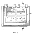
FIG. 2 is an OD/top view of the BOAS ofFIG. 1 . -
FIG. 3 is a longitudinal sectional view of the BOAS ofFIG. 2 taken along line 3-3. -
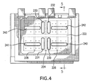
FIG. 4 is an OD/top view of an alternate BOAS. -
FIG. 5 is a longitudinal sectional view of the BOAS ofFIG. 4 , taken along line 5-5. - Like reference numbers and designations in the various drawings indicate like elements.
-
FIG. 1 shows blade outer air seal (BOAS) 20. The BOAS has amain body portion 22 having a leading/upstream/forward end 24 and a trailing/downstream/aft end 26.FIG. 1 further shows an approximate longitudinal/overall-downstream/aftward direction 500, an approximate radialoutward direction 502, and an approximatecircumferential direction 504. The body has first and second circumferential ends ormatefaces inboard face 32 and an outer diameter (OD)/outboard face 34. - To mount the BOAS to environmental structure 40 (
FIG. 3 ), the exemplary BOAS has a plurality of mounting hooks. The exemplary BOAS has a singleforward mounting hook 42 having a forwardly-projecting distal portion recessed aft of theforward end 24. The exemplary BOAS has a series of fouraft hooks 44 each having a rearwardly-projecting distal portion protruding beyond theaft end 26. - The BOAS has a
wall structure 46 circumscribing/surrounding a recess/cavity 48 described in further detail below. The exemplary distal portion of theforward hook 42 is formed as a full width lip extending from a front segment of the wall 46 (FIG. 3 ). The exemplary proximal portions of theaft hooks 44 extend upward from an aft segment of thewall 46. A floor orbase 50 of the chamber is locally formed by a central portion of theOD face 34. The ID face may bear athermal barrier coating 52 having an exposedsurface 54. - A circumferential ring array of a plurality of the
BOAS 20 may encircle an associated blade stage of a gas turbine engine. The assembled ID faces 32/coating surfaces 54 thus locally bound an outboard extreme of the core flowpath 56 (FIG. 3 ). The BOAS 20 may have features for interlocking the array. Theexemplary matefaces adjacent BOAS 20 or may include finger joints. - The BOAS may be air-cooled. For example, bleed air may be directed to a chamber 58 (
FIG. 3 ) immediately outboard of abaffle plate 60 that extends across thechamber 48. A perimeter portion of the underside/ID surface 61 of thebaffle plate 60 may sit atop and be welded or brazed to ashoulder surface 62 of thewall 46. The bleed air may be directed throughimpingement feed holes 64 in theplate 60 to the inboard portion of thechamber 48. Air may exit thechamber 48 throughdischarge passageways 70.Exemplary passageways 70 extend frominlets 72 at thechamber 48 tooutlets 74 along the TBC 52. - The exemplary casting includes a
circumferential rib 80 in thechamber 48. Theexemplary rib 80 is partial shoulder height so that its outboard surface 82 (FIG. 3 ) is recessed below theunderside 61 of theplate 60. The exemplary casting further includes an axial/longitudinal rib 84 in thechamber 48. Theexemplary rib 84 is full shoulder height so that itsoutboard surface 86 may contact theunderside 61 of the plate 60 (e.g., and be secured thereto as the plate is secured to the shoulder surface 62). The ribs divide the portion of thechamber 48 below theplate 60 into four quadrant (sub)chambers/cavities FIG. 2 ). Agap 94 is formed between thesurface 82 and theplate underside 61 on each side of theaxial rib 84. For purposes of description, reference to a singlecircumferential rib 80 having portions on each side of theaxial rib 84 is equivalent to referencing one circumferential rib extending from the first side of the axial rib and a second circumferential rib extending from the second side of the axial rib. -
FIG. 3 schematically shows ablade 100 of the associated stage. The blade has an airfoil with a leadingedge 102, atrailing edge 104, and a tip 106. Action of the airfoil imposes a pressure gradient to theairflow 520 passing downstream along thesurface 54. For example, the gradient may provide an exemplary 50% drop in pressure from a leading group of theoutlets 74 to a trailing group of theoutlets 74. This pressure difference may pose difficulties in cooling the BOAS. In particular, feeding from acommon chamber 48 may end up providing one or both of excessive flow through the trailing holes and insufficient flow through the leading holes. To address this, the prior art has tailored the distribution of feed air to fully isolated fore and aft chambers. Nevertheless, there remain such flow problems within either of the two chambers. - To address this problem, the quadrant chambers 90-93 may each be divided into separate upstream (fore) and downstream (aft) regions, respectively. The division may be only partial, with an open
restricted region 118 separating upstream and downstream regions from each other. Each exemplary restriction is formed by achannel baffle plate 60 projecting as a blister toward thefloor 50. The exemplary channels are essentially full width of the associated half of thechamber 48 and provide the restrictedregion 124 with a height H2 approximately 30-60% of a height H1 of remaining majority portions of the chamber. Exemplary heights are essentially uniform, but may also represent other characteristic heights (e.g., mean, modal, or median). An exemplary height H3 of thegap 94 is less than 60% of H1 , more narrowly less than 40% or 5-30%. - The centers of the
exemplary channels quadrant chambers exemplary channels quadrant chambers exemplary chambers 90/91 and 92/93 respectively have lengths L1 and L2. The center of theexemplary channels 120/121 and 122/123 are respectively at lengths L3 and L4 downstream of the downstream faces of the forward leg of thewall 46 and wall/rib 80. - In an exemplary model of a steady state operating condition, an exemplary pressure in the
flowpath 56 at the leading group ofoutlets 74 is an exemplary 300-400 psia (2.07-2.76 MPaa) whereas the pressure at a trailing/downstream group is about 50-75% of that. Four upstream-to-downstream groups ofholes 70 are fed from thecavities outlets 74 of the downstreammost of these four is proportionately less than at the leading group. The size/number/distribution of holes along thecavity 90 may be selected to provide a pressure in thecavity 90 above that of the leading group of holes (e.g., 5-15% above or about 20-40 psi (138-276 kPa) above). - Four upstream-to-downstream groups of
holes 70 are fed from thecavities outlets 74 of the upstreammost of these four is proportionately above that of the trailing group. The heights H2 and H3 are selected to be sufficiently small to permit an effective pressure difference between the four distinct upstream todownstream regions highest pressure outlets 74. The positions of the channels may be selected to apportion theholes 70 between the regions in such a way as to minimize total air requirements for a given cooling level. - Zero values of H2 and/or H3 might interfere with local cooling and might permit rubbing between the plate and body. Thus a higher value may be preferred. Plate hole diameter for holes 64 (if any) along the channel and the quantity/distribution of such holes may be chosen in combination with H2 to provide desired local impingement cooling. The quantities of the
holes 64 along eachregion - Additional variations (not shown) include circumferential asymmetries in the distribution of the ribs, channels or holes in the plate or casting.
-
FIGS. 4 and5 show an alternative BOAS 220 otherwise similar but wherein a centralcircumferential rib 222 is full height and a centralaxial rib 224 is partial height. Each resulting chamber quadrant may be further divided in half by one of first and second partial heightaxial ribs elongate channel axial rib 224. Circumferentiallyelongate channels - The BOAS may be formed as a reengineering of a baseline BOAS configuration. In one reengineering example, the original casting has a full-height circumferential rib and no axial ribs. The cover plate is a flat (technically arcuate at the local engine radius) and unchanneled. The engineering may preserve the basic shape of the casting and plate while making the identified changes regarding ribs and channels and associated optimization in whole distribution in the casting and plate. Alternative or further refinements may be made preserving casting geometry (i.e., rib location and size) while altering channel geometry. Other variations may involve shifting of existing ribs. With stamped channels, varying channel geometry may be much easier and less expensive than varying casting geometry.
- The reengineering may also shift the distribution of the
holes 64. An exemplary shift is an overall forward shift (e.g., measured as a mean or other average). An exemplary shift combined with rib and/or channel addition or modification may reduce the total cooling air flow by increasing the overall restriction provided by the plate and casting combination. - One or more embodiments have been described. Nevertheless, it will be understood that various modifications may be made without departing from the scope of the invention. For example, when implemented in the reengineering of a baseline BOAS, or using existing manufacturing techniques and equipment, details of the baseline BOAS or existing techniques or equipment may influence details of any particular implementation. Accordingly, other embodiments are within the scope of the following claims.
Claims (20)
- A turbine engine blade outer air seal segment (20) comprising:a body (22) having:a base portion (50) having:a transversely concave ID face (32);a forward end (24);an aft end (26); andfirst and second circumferential edges (28, 30); andat least one mounting hook (42); andat least one cover plate (60) secured to the body (22) to define at least one cavity (90...93) and having a plurality of feed holes (64), a plurality of outlet holes (70) extending through the base portion (50) to the ID face (32),
wherein:at least one of the base portion (50) and cover plate (60) comprises at least one protruding portion protruding into the cavity to form at least partial restrictions (118) separating circumferentially and fore-aft offset compartment portions. - The segment of claim 1 further comprising:a coating (52) on the base portion ID face (32).
- The apparatus of claim 1 or 2 wherein:the at least one mounting hook includes:at least one front mounting hook (42); andat least one aft mounting hook (44).
- The apparatus of any preceding claim wherein the at least one protruding portion comprises:at least one blister on the cover plate (60).
- The apparatus of any preceding claim wherein the at least one protruding portion comprises:an essentially full height axial rib (84) of the body (22); a partial height circumferential rib (80) of the body (22), the axial rib (84) and circumferential rib (80) cooperating to divide the compartment into four quadrants 90....93); andfour circumferentially elongate blisters (120....123) on the cover plate (60), each along a respective one of the four quadrants (90....93).
- The apparatus of claim 5 wherein the at least one protruding portion consists essentially of:said axial rib (84);said circumferential rib (80); andsaid four circumferentially elongate blisters (120...123).
- The apparatus of any of claims 1 to 4 wherein the at least one protruding portion comprises:a partial height axial rib (224) of the body (22);an essentially full height circumferential rib (222) of the body (22), the axial rib (224) and circumferential rib (222) cooperating to divide the compartment into four quadrants;four circumferentially elongate blisters (240.....243) on the cover plate (60), each along a respective one of the four quadrants; andfour axially elongate blisters (230...233) on the cover plate (60), each along a respective one of the four quadrants.
- The apparatus of claim 7 wherein:each of said four axially elongate blisters (230....233) is positioned between said axial rib (224) and an associated one of the circumferentially elongate blisters (240....243).
- The apparatus of claim 7 or 8 wherein the axial rib (224) is a first axial rib and the at least one protruding portion further comprises:a second partial height axial rib (226) on a first side of the first axial rib (224); anda third partial height axial rib (228) on a first side of the first axial rib (224).
- The apparatus of claim 9 wherein the at least one protruding portion consists essentially of:said first, second, and third axial ribs (224, 226);said circumferential rib (222);said four circumferentially elongate blisters (240....243); andsaid four axially elongate blisters (230....233).
- The apparatus of any preceding claim wherein:the cover plate (60) is a stamping;the body.(22) is a casting having a thermal barrier coating (52) on the ID face (32); andthe cover plate (60) is welded to the body (22).
- A method for engineering the segment of any preceding claim comprising:determining an indication of an operational core flow pressure drop along the ID face (32); andselecting a characteristic of the protruding portion to provide a fore-aft pressure drop within the cavity.
- The method of claim 12 wherein:a distribution of holes (64) in the plate (60) is shifted forward.
- A turbine engine blade outer air seal segment (20) comprising:a body (22) having:a base portion (50) having:a transversely concave ID face (32);a forward end (24);an aft end (26); andfirst and second circumferential edges 26, 28); andat least one mounting hook (42); andat least one cover plate (60) secured to the body (22) to define at least one cavity (90...93) and having a plurality of feed holes (64), a plurality of outlet holes (70) extending through the base portion (50) to the ID face (32),
wherein:at least one of the base portion (50) and cover plate (60) comprises means for providing an operational axial/circumferential pressure gradient within the cavity to compensate for an operational core flow pressure drop along the ID face (32). - The segment of claim 14 wherein:the means comprises a constriction of the cavity.
- A method for reengineering a configuration of a turbine engine blade outer air seal segment (20) from a baseline configuration to a reengineered configuration, the baseline configuration comprising:a body (22) having:a base portion (50) having:a transversely concave ID face (32);a forward end (24);an aft end (26); andfirst and second circumferential edges (28, 30); andat least one mounting hook (42); andat least one cover plate (60) secured to the body (22)to define at least one impingement cavity (90....93) andhaving a plurality of feed holes (64), a plurality of outlet holes (70) extending through the base portion (50) to the ID face (32),
the method comprising:adding a protrusion into the cavity from at least one of the cover plate (60) and base portion 50). - The method of claim 16 further comprising:determining an indication of an operational core flow pressure drop along the ID face (32); andselecting a characteristic of the protrusion to provide a fore-aft pressure drop within the cavity.
- The method of claim 16 or 17 wherein:the protrusion comprises a blister.
- The method of claim 16, 17 or 18 wherein:the baseline configuration has a mean location of the feed holes (64) ; andthe reengineered configuration has a mean location of the feed holes (64) forward of the baseline configuration mean location.
- The method of any of claims 16 to 19 wherein:relative to the baseline configuration, the reengineered configuration has a reduced cooling air requirement for a given level of cooling.
Applications Claiming Priority (1)
| Application Number | Priority Date | Filing Date | Title |
|---|---|---|---|
| US11/712,863 US8123466B2 (en) | 2007-03-01 | 2007-03-01 | Blade outer air seal |
Publications (3)
| Publication Number | Publication Date |
|---|---|
| EP1965032A2 true EP1965032A2 (en) | 2008-09-03 |
| EP1965032A3 EP1965032A3 (en) | 2013-11-20 |
| EP1965032B1 EP1965032B1 (en) | 2015-05-06 |
Family
ID=39512669
Family Applications (1)
| Application Number | Title | Priority Date | Filing Date |
|---|---|---|---|
| EP20080250689 Active EP1965032B1 (en) | 2007-03-01 | 2008-02-29 | Blade outer air seal |
Country Status (2)
| Country | Link |
|---|---|
| US (1) | US8123466B2 (en) |
| EP (1) | EP1965032B1 (en) |
Cited By (8)
| Publication number | Priority date | Publication date | Assignee | Title |
|---|---|---|---|---|
| FR2962484A1 (en) * | 2010-07-08 | 2012-01-13 | Snecma | Turbine shroud sector for e.g. turbojet of aircraft, has perforations formed on two sides of partition such that disturbance of cooling gas flow leaving perforations on one side is limited by gas flow leaving perforations on other side |
| CN102588013A (en) * | 2011-01-06 | 2012-07-18 | 通用电气公司 | Impingement plate for turbomachine components and components equipped therewith |
| CN102733860A (en) * | 2011-04-13 | 2012-10-17 | 通用电气公司 | Turbine shroud segment cooling system and method |
| CN103422917A (en) * | 2012-05-25 | 2013-12-04 | 通用电气公司 | Turbine shroud cooling assembly for a gas turbine system |
| EP2877709A4 (en) * | 2012-07-27 | 2016-08-03 | United Technologies Corp | OIL SEAL FOR EXTERNAL BLADE AIR FOR A GAS TURBINE |
| EP3557004A1 (en) * | 2018-04-17 | 2019-10-23 | United Technologies Corporation | Seal assembly for gas turbine engine |
| WO2020239560A1 (en) * | 2019-05-29 | 2020-12-03 | Siemens Aktiengesellschaft | Heatshield for a gas turbine engine |
| RU2788802C1 (en) * | 2019-05-29 | 2023-01-24 | Сименс Энерджи Глобал Гмбх Унд Ко. Кг | Heat shield for gas turbine engine |
Families Citing this family (56)
| Publication number | Priority date | Publication date | Assignee | Title |
|---|---|---|---|---|
| US8439639B2 (en) * | 2008-02-24 | 2013-05-14 | United Technologies Corporation | Filter system for blade outer air seal |
| CH700687A1 (en) * | 2009-03-30 | 2010-09-30 | Alstom Technology Ltd | Chilled component for a gas turbine. |
| US8556575B2 (en) * | 2010-03-26 | 2013-10-15 | United Technologies Corporation | Blade outer seal for a gas turbine engine |
| US8876458B2 (en) * | 2011-01-25 | 2014-11-04 | United Technologies Corporation | Blade outer air seal assembly and support |
| US8826668B2 (en) * | 2011-08-02 | 2014-09-09 | Siemens Energy, Inc. | Two stage serial impingement cooling for isogrid structures |
| US9238970B2 (en) * | 2011-09-19 | 2016-01-19 | United Technologies Corporation | Blade outer air seal assembly leading edge core configuration |
| US8998572B2 (en) | 2012-06-04 | 2015-04-07 | United Technologies Corporation | Blade outer air seal for a gas turbine engine |
| US20130340966A1 (en) | 2012-06-21 | 2013-12-26 | United Technologies Corporation | Blade outer air seal hybrid casting core |
| US9574455B2 (en) * | 2012-07-16 | 2017-02-21 | United Technologies Corporation | Blade outer air seal with cooling features |
| US9506367B2 (en) | 2012-07-20 | 2016-11-29 | United Technologies Corporation | Blade outer air seal having inward pointing extension |
| US9115596B2 (en) | 2012-08-07 | 2015-08-25 | United Technologies Corporation | Blade outer air seal having anti-rotation feature |
| US9145789B2 (en) * | 2012-09-05 | 2015-09-29 | General Electric Company | Impingement plate for damping and cooling shroud assembly inter segment seals |
| US20140127006A1 (en) * | 2012-11-05 | 2014-05-08 | United Technologies Corporation | Blade outer air seal |
| US9803491B2 (en) | 2012-12-31 | 2017-10-31 | United Technologies Corporation | Blade outer air seal having shiplap structure |
| EP2961930B1 (en) | 2013-02-26 | 2020-05-27 | United Technologies Corporation | Edge treatment for blade outer air seal segment |
| US10100737B2 (en) | 2013-05-16 | 2018-10-16 | Siemens Energy, Inc. | Impingement cooling arrangement having a snap-in plate |
| WO2014204574A2 (en) * | 2013-06-21 | 2014-12-24 | United Technologies Corporation | Seals for gas turbine engine |
| WO2015031764A1 (en) * | 2013-08-29 | 2015-03-05 | United Technologies Corporation | Blade outer air seal made of ceramic matrix composite |
| US10309255B2 (en) * | 2013-12-19 | 2019-06-04 | United Technologies Corporation | Blade outer air seal cooling passage |
| US9151175B2 (en) | 2014-02-25 | 2015-10-06 | Siemens Aktiengesellschaft | Turbine abradable layer with progressive wear zone multi level ridge arrays |
| US9243511B2 (en) | 2014-02-25 | 2016-01-26 | Siemens Aktiengesellschaft | Turbine abradable layer with zig zag groove pattern |
| US8939705B1 (en) | 2014-02-25 | 2015-01-27 | Siemens Energy, Inc. | Turbine abradable layer with progressive wear zone multi depth grooves |
| US9249680B2 (en) | 2014-02-25 | 2016-02-02 | Siemens Energy, Inc. | Turbine abradable layer with asymmetric ridges or grooves |
| RU2016134446A (en) | 2014-02-25 | 2018-03-29 | Сименс Акциенгезелльшафт | THERMAL BARRIER COATING OF A TURBINE COMPONENT WITH MATERIAL PROPERTIES VARIABLE DEPTH |
| US8939706B1 (en) | 2014-02-25 | 2015-01-27 | Siemens Energy, Inc. | Turbine abradable layer with progressive wear zone having a frangible or pixelated nib surface |
| US8939707B1 (en) | 2014-02-25 | 2015-01-27 | Siemens Energy, Inc. | Turbine abradable layer with progressive wear zone terraced ridges |
| US8939716B1 (en) | 2014-02-25 | 2015-01-27 | Siemens Aktiengesellschaft | Turbine abradable layer with nested loop groove pattern |
| EP3259452A2 (en) | 2015-02-18 | 2017-12-27 | Siemens Aktiengesellschaft | Forming cooling passages in combustion turbine superalloy castings |
| US10190435B2 (en) | 2015-02-18 | 2019-01-29 | Siemens Aktiengesellschaft | Turbine shroud with abradable layer having ridges with holes |
| US9771814B2 (en) | 2015-03-09 | 2017-09-26 | United Technologies Corporation | Tolerance resistance coverplates |
| DE102015217078A1 (en) * | 2015-09-07 | 2017-03-09 | MTU Aero Engines AG | Device for limiting a flow channel of a turbomachine |
| US10443426B2 (en) | 2015-12-17 | 2019-10-15 | United Technologies Corporation | Blade outer air seal with integrated air shield |
| US10138749B2 (en) | 2016-03-16 | 2018-11-27 | United Technologies Corporation | Seal anti-rotation feature |
| US10132184B2 (en) | 2016-03-16 | 2018-11-20 | United Technologies Corporation | Boas spring loaded rail shield |
| US10138750B2 (en) | 2016-03-16 | 2018-11-27 | United Technologies Corporation | Boas segmented heat shield |
| US10337346B2 (en) | 2016-03-16 | 2019-07-02 | United Technologies Corporation | Blade outer air seal with flow guide manifold |
| US10443424B2 (en) | 2016-03-16 | 2019-10-15 | United Technologies Corporation | Turbine engine blade outer air seal with load-transmitting carriage |
| US10513943B2 (en) * | 2016-03-16 | 2019-12-24 | United Technologies Corporation | Boas enhanced heat transfer surface |
| US10161258B2 (en) | 2016-03-16 | 2018-12-25 | United Technologies Corporation | Boas rail shield |
| US10107129B2 (en) | 2016-03-16 | 2018-10-23 | United Technologies Corporation | Blade outer air seal with spring centering |
| US10422240B2 (en) | 2016-03-16 | 2019-09-24 | United Technologies Corporation | Turbine engine blade outer air seal with load-transmitting cover plate |
| US10422241B2 (en) | 2016-03-16 | 2019-09-24 | United Technologies Corporation | Blade outer air seal support for a gas turbine engine |
| US10415414B2 (en) | 2016-03-16 | 2019-09-17 | United Technologies Corporation | Seal arc segment with anti-rotation feature |
| US10443616B2 (en) | 2016-03-16 | 2019-10-15 | United Technologies Corporation | Blade outer air seal with centrally mounted seal arc segments |
| US10563531B2 (en) | 2016-03-16 | 2020-02-18 | United Technologies Corporation | Seal assembly for gas turbine engine |
| GB201720121D0 (en) | 2017-12-04 | 2018-01-17 | Siemens Ag | Heatshield for a gas turbine engine |
| US10502093B2 (en) * | 2017-12-13 | 2019-12-10 | Pratt & Whitney Canada Corp. | Turbine shroud cooling |
| US10914192B2 (en) * | 2018-09-25 | 2021-02-09 | Raytheon Technologies Corporation | Impingement cooling for gas turbine engine component |
| US11525401B2 (en) * | 2021-01-11 | 2022-12-13 | Honeywell International Inc. | Impingement baffle for gas turbine engine |
| KR102510537B1 (en) * | 2021-02-24 | 2023-03-15 | 두산에너빌리티 주식회사 | Ring segment and turbo-machine comprising the same |
| JP2023133660A (en) * | 2022-03-14 | 2023-09-27 | 三菱重工業株式会社 | High-temperature parts, rotating machinery, and manufacturing methods for high-temperature parts |
| EP4276283B1 (en) * | 2022-05-13 | 2026-01-28 | Siemens Energy Global GmbH & Co. KG | Ring segment assembly in gas turbine engine |
| EP4343119A1 (en) * | 2022-09-23 | 2024-03-27 | Siemens Energy Global GmbH & Co. KG | Ring segment for gas turbine engine |
| GB202216827D0 (en) * | 2022-11-11 | 2022-12-28 | Rolls Royce Plc | A method of manufacturing a turbine component |
| US12467629B1 (en) * | 2025-01-15 | 2025-11-11 | Rtx Corporation | CMC component with cover plate |
| US12613034B1 (en) * | 2025-01-29 | 2026-04-28 | Rtx Corporation | Ceramic matrix composite component with corrugated wall |
Citations (1)
| Publication number | Priority date | Publication date | Assignee | Title |
|---|---|---|---|---|
| US6393331B1 (en) | 1998-12-16 | 2002-05-21 | United Technologies Corporation | Method of designing a turbine blade outer air seal |
Family Cites Families (22)
| Publication number | Priority date | Publication date | Assignee | Title |
|---|---|---|---|---|
| BE756582A (en) * | 1969-10-02 | 1971-03-01 | Gen Electric | CIRCULAR SCREEN AND SCREEN HOLDER WITH TEMPERATURE ADJUSTMENT FOR TURBOMACHINE |
| US3603599A (en) * | 1970-05-06 | 1971-09-07 | Gen Motors Corp | Cooled seal |
| GB1519590A (en) * | 1974-11-11 | 1978-08-02 | Rolls Royce | Gas turbine engine |
| US4135851A (en) * | 1977-05-27 | 1979-01-23 | The United States Of America As Represented By The Administrator Of The National Aeronautics And Space Administration | Composite seal for turbomachinery |
| US4303371A (en) * | 1978-06-05 | 1981-12-01 | General Electric Company | Shroud support with impingement baffle |
| US4526226A (en) * | 1981-08-31 | 1985-07-02 | General Electric Company | Multiple-impingement cooled structure |
| US4642024A (en) * | 1984-12-05 | 1987-02-10 | United Technologies Corporation | Coolable stator assembly for a rotary machine |
| US5165847A (en) * | 1991-05-20 | 1992-11-24 | General Electric Company | Tapered enlargement metering inlet channel for a shroud cooling assembly of gas turbine engines |
| US5399066A (en) * | 1993-09-30 | 1995-03-21 | General Electric Company | Integral clearance control impingement manifold and environmental shield |
| US5480281A (en) * | 1994-06-30 | 1996-01-02 | General Electric Co. | Impingement cooling apparatus for turbine shrouds having ducts of increasing cross-sectional area in the direction of post-impingement cooling flow |
| US5609469A (en) * | 1995-11-22 | 1997-03-11 | United Technologies Corporation | Rotor assembly shroud |
| US6139257A (en) * | 1998-03-23 | 2000-10-31 | General Electric Company | Shroud cooling assembly for gas turbine engine |
| US6126389A (en) * | 1998-09-02 | 2000-10-03 | General Electric Co. | Impingement cooling for the shroud of a gas turbine |
| US6331096B1 (en) * | 2000-04-05 | 2001-12-18 | General Electric Company | Apparatus and methods for impingement cooling of an undercut region adjacent a side wall of a turbine nozzle segment |
| US6354795B1 (en) * | 2000-07-27 | 2002-03-12 | General Electric Company | Shroud cooling segment and assembly |
| JP4698847B2 (en) * | 2001-01-19 | 2011-06-08 | 三菱重工業株式会社 | Gas turbine split ring |
| US7033138B2 (en) * | 2002-09-06 | 2006-04-25 | Mitsubishi Heavy Industries, Ltd. | Ring segment of gas turbine |
| US6877952B2 (en) * | 2002-09-09 | 2005-04-12 | Florida Turbine Technologies, Inc | Passive clearance control |
| FR2857406B1 (en) * | 2003-07-10 | 2005-09-30 | Snecma Moteurs | COOLING THE TURBINE RINGS |
| FR2858652B1 (en) * | 2003-08-06 | 2006-02-10 | Snecma Moteurs | DEVICE FOR CONTROLLING PLAY IN A GAS TURBINE |
| US7306424B2 (en) * | 2004-12-29 | 2007-12-11 | United Technologies Corporation | Blade outer seal with micro axial flow cooling system |
| US8439629B2 (en) * | 2007-03-01 | 2013-05-14 | United Technologies Corporation | Blade outer air seal |
-
2007
- 2007-03-01 US US11/712,863 patent/US8123466B2/en active Active
-
2008
- 2008-02-29 EP EP20080250689 patent/EP1965032B1/en active Active
Patent Citations (1)
| Publication number | Priority date | Publication date | Assignee | Title |
|---|---|---|---|---|
| US6393331B1 (en) | 1998-12-16 | 2002-05-21 | United Technologies Corporation | Method of designing a turbine blade outer air seal |
Cited By (16)
| Publication number | Priority date | Publication date | Assignee | Title |
|---|---|---|---|---|
| FR2962484A1 (en) * | 2010-07-08 | 2012-01-13 | Snecma | Turbine shroud sector for e.g. turbojet of aircraft, has perforations formed on two sides of partition such that disturbance of cooling gas flow leaving perforations on one side is limited by gas flow leaving perforations on other side |
| CN102588013A (en) * | 2011-01-06 | 2012-07-18 | 通用电气公司 | Impingement plate for turbomachine components and components equipped therewith |
| CN102588013B (en) * | 2011-01-06 | 2016-02-10 | 通用电气公司 | For turbine components striking plate and equip its component |
| CN102733860A (en) * | 2011-04-13 | 2012-10-17 | 通用电气公司 | Turbine shroud segment cooling system and method |
| CN102733860B (en) * | 2011-04-13 | 2016-05-25 | 通用电气公司 | Turbine shroud portion section cooling system and method |
| CN103422917A (en) * | 2012-05-25 | 2013-12-04 | 通用电气公司 | Turbine shroud cooling assembly for a gas turbine system |
| US10436054B2 (en) | 2012-07-27 | 2019-10-08 | United Technologies Corporation | Blade outer air seal for a gas turbine engine |
| US9617866B2 (en) | 2012-07-27 | 2017-04-11 | United Technologies Corporation | Blade outer air seal for a gas turbine engine |
| EP2877709A4 (en) * | 2012-07-27 | 2016-08-03 | United Technologies Corp | OIL SEAL FOR EXTERNAL BLADE AIR FOR A GAS TURBINE |
| EP3557004A1 (en) * | 2018-04-17 | 2019-10-23 | United Technologies Corporation | Seal assembly for gas turbine engine |
| US10801351B2 (en) | 2018-04-17 | 2020-10-13 | Raytheon Technologies Corporation | Seal assembly for gas turbine engine |
| WO2020239560A1 (en) * | 2019-05-29 | 2020-12-03 | Siemens Aktiengesellschaft | Heatshield for a gas turbine engine |
| CN113950566A (en) * | 2019-05-29 | 2022-01-18 | 西门子能源环球有限责任两合公司 | Heat shields for gas turbine engines |
| RU2788802C1 (en) * | 2019-05-29 | 2023-01-24 | Сименс Энерджи Глобал Гмбх Унд Ко. Кг | Heat shield for gas turbine engine |
| CN113950566B (en) * | 2019-05-29 | 2024-06-14 | 西门子能源环球有限责任两合公司 | Heat shield for a gas turbine engine |
| US12025019B2 (en) | 2019-05-29 | 2024-07-02 | Siemens Energy Global GmbH & Co. KG | Heatshield for a gas turbine engine |
Also Published As
| Publication number | Publication date |
|---|---|
| US20080211192A1 (en) | 2008-09-04 |
| US8123466B2 (en) | 2012-02-28 |
| EP1965032A3 (en) | 2013-11-20 |
| EP1965032B1 (en) | 2015-05-06 |
Similar Documents
| Publication | Publication Date | Title |
|---|---|---|
| EP1965032B1 (en) | Blade outer air seal | |
| US8439629B2 (en) | Blade outer air seal | |
| US7553128B2 (en) | Blade outer air seals | |
| US7625172B2 (en) | Vane platform cooling | |
| EP1443178B1 (en) | Turbine blade | |
| US8303247B2 (en) | Blade outer air seal | |
| EP2702250B1 (en) | A method of forming a multi-panel outer wall of a component for use in a gas turbine engine | |
| EP1944474B1 (en) | Gas turbine shroud seal and corresponding gas turbine engine | |
| US7621719B2 (en) | Multiple cooling schemes for turbine blade outer air seal | |
| US5387085A (en) | Turbine blade composite cooling circuit | |
| EP2851517B1 (en) | A shroud arrangement for a gas turbine engine | |
| US20140341711A1 (en) | Shroud arrangement for a gas turbine engine | |
| EP3252272B1 (en) | Blade and gas turbine equipped with same | |
| EP3034806A1 (en) | Blade outer air seals, cores, and manufacture methods | |
| US9920647B2 (en) | Dual source cooling air shroud arrangement for a gas turbine engine | |
| JP5965633B2 (en) | Apparatus and method for cooling the platform area of a turbine rotor blade | |
| EP1156187A2 (en) | Nozzle cavity insert having impingement and convection cooling regions | |
| EP4283094B1 (en) | Turbine component with stress relieving cooling circuit | |
| EP1748155B1 (en) | Cooled shroud assembly and method of cooling a shroud | |
| EP2067929B1 (en) | Air-cooled gas turbine engine vane | |
| US6824352B1 (en) | Vane enhanced trailing edge cooling design | |
| JPH11280407A (en) | Gas turbine cooling stationary blade | |
| WO2019245546A1 (en) | Cooled turbine blade assembly, corresponding methods for cooling and manufacturing | |
| GB2572191A (en) | A lockplate for a bladed rotor arrangement |
Legal Events
| Date | Code | Title | Description |
|---|---|---|---|
| PUAI | Public reference made under article 153(3) epc to a published international application that has entered the european phase |
Free format text: ORIGINAL CODE: 0009012 |
|
| AK | Designated contracting states |
Kind code of ref document: A2 Designated state(s): AT BE BG CH CY CZ DE DK EE ES FI FR GB GR HR HU IE IS IT LI LT LU LV MC MT NL NO PL PT RO SE SI SK TR |
|
| AX | Request for extension of the european patent |
Extension state: AL BA MK RS |
|
| PUAL | Search report despatched |
Free format text: ORIGINAL CODE: 0009013 |
|
| AK | Designated contracting states |
Kind code of ref document: A3 Designated state(s): AT BE BG CH CY CZ DE DK EE ES FI FR GB GR HR HU IE IS IT LI LT LU LV MC MT NL NO PL PT RO SE SI SK TR |
|
| AX | Request for extension of the european patent |
Extension state: AL BA MK RS |
|
| RIC1 | Information provided on ipc code assigned before grant |
Ipc: F02C 7/18 20060101ALN20131011BHEP Ipc: F01D 11/08 20060101AFI20131011BHEP Ipc: F01D 25/24 20060101ALI20131011BHEP Ipc: F01D 9/04 20060101ALN20131011BHEP |
|
| 17P | Request for examination filed |
Effective date: 20140520 |
|
| RBV | Designated contracting states (corrected) |
Designated state(s): AT BE BG CH CY CZ DE DK EE ES FI FR GB GR HR HU IE IS IT LI LT LU LV MC MT NL NO PL PT RO SE SI SK TR |
|
| AKX | Designation fees paid |
Designated state(s): DE GB |
|
| GRAP | Despatch of communication of intention to grant a patent |
Free format text: ORIGINAL CODE: EPIDOSNIGR1 |
|
| RIC1 | Information provided on ipc code assigned before grant |
Ipc: F01D 25/24 20060101ALI20141002BHEP Ipc: F01D 9/04 20060101ALN20141002BHEP Ipc: F02C 7/18 20060101ALN20141002BHEP Ipc: F01D 11/08 20060101AFI20141002BHEP |
|
| RIC1 | Information provided on ipc code assigned before grant |
Ipc: F01D 9/04 20060101ALN20141010BHEP Ipc: F02C 7/18 20060101ALN20141010BHEP Ipc: F01D 25/24 20060101ALI20141010BHEP Ipc: F01D 11/08 20060101AFI20141010BHEP |
|
| INTG | Intention to grant announced |
Effective date: 20141030 |
|
| GRAP | Despatch of communication of intention to grant a patent |
Free format text: ORIGINAL CODE: EPIDOSNIGR1 |
|
| RIC1 | Information provided on ipc code assigned before grant |
Ipc: F01D 11/08 20060101AFI20150120BHEP Ipc: F02C 7/18 20060101ALN20150120BHEP Ipc: F01D 25/24 20060101ALI20150120BHEP Ipc: F01D 9/04 20060101ALN20150120BHEP |
|
| INTG | Intention to grant announced |
Effective date: 20150205 |
|
| GRAS | Grant fee paid |
Free format text: ORIGINAL CODE: EPIDOSNIGR3 |
|
| GRAA | (expected) grant |
Free format text: ORIGINAL CODE: 0009210 |
|
| AK | Designated contracting states |
Kind code of ref document: B1 Designated state(s): DE GB |
|
| REG | Reference to a national code |
Ref country code: GB Ref legal event code: FG4D |
|
| REG | Reference to a national code |
Ref country code: DE Ref legal event code: R096 Ref document number: 602008038025 Country of ref document: DE Effective date: 20150618 |
|
| REG | Reference to a national code |
Ref country code: DE Ref legal event code: R097 Ref document number: 602008038025 Country of ref document: DE |
|
| PLBE | No opposition filed within time limit |
Free format text: ORIGINAL CODE: 0009261 |
|
| STAA | Information on the status of an ep patent application or granted ep patent |
Free format text: STATUS: NO OPPOSITION FILED WITHIN TIME LIMIT |
|
| 26N | No opposition filed |
Effective date: 20160209 |
|
| REG | Reference to a national code |
Ref country code: DE Ref legal event code: R082 Ref document number: 602008038025 Country of ref document: DE Representative=s name: SCHMITT-NILSON SCHRAUD WAIBEL WOHLFROM PATENTA, DE |
|
| REG | Reference to a national code |
Ref country code: DE Ref legal event code: R082 Ref document number: 602008038025 Country of ref document: DE Representative=s name: SCHMITT-NILSON SCHRAUD WAIBEL WOHLFROM PATENTA, DE Ref country code: DE Ref legal event code: R081 Ref document number: 602008038025 Country of ref document: DE Owner name: UNITED TECHNOLOGIES CORP. (N.D.GES.D. STAATES , US Free format text: FORMER OWNER: UNITED TECHNOLOGIES CORPORATION, HARTFORD, CONN., US |
|
| REG | Reference to a national code |
Ref country code: DE Ref legal event code: R081 Ref document number: 602008038025 Country of ref document: DE Owner name: RAYTHEON TECHNOLOGIES CORPORATION (N.D.GES.D.S, US Free format text: FORMER OWNER: UNITED TECHNOLOGIES CORP. (N.D.GES.D. STAATES DELAWARE), FARMINGTON, CONN., US Ref country code: DE Ref legal event code: R081 Ref document number: 602008038025 Country of ref document: DE Owner name: RTX CORPORATION (N.D.GES.D. STAATES DELAWARE),, US Free format text: FORMER OWNER: UNITED TECHNOLOGIES CORP. (N.D.GES.D. STAATES DELAWARE), FARMINGTON, CONN., US |
|
| P01 | Opt-out of the competence of the unified patent court (upc) registered |
Effective date: 20230519 |
|
| REG | Reference to a national code |
Ref country code: DE Ref legal event code: R081 Ref document number: 602008038025 Country of ref document: DE Owner name: RTX CORPORATION (N.D.GES.D. STAATES DELAWARE),, US Free format text: FORMER OWNER: RAYTHEON TECHNOLOGIES CORPORATION (N.D.GES.D.STAATES DELAWARE), ARLINGTON, VA, US |
|
| PGFP | Annual fee paid to national office [announced via postgrant information from national office to epo] |
Ref country code: GB Payment date: 20260121 Year of fee payment: 19 |
|
| PGFP | Annual fee paid to national office [announced via postgrant information from national office to epo] |
Ref country code: DE Payment date: 20260121 Year of fee payment: 19 |