EP1964588A1 - Shield for covering the extremity of an administration device or assembly, an administration assembly and an administration device - Google Patents
Shield for covering the extremity of an administration device or assembly, an administration assembly and an administration device Download PDFInfo
- Publication number
- EP1964588A1 EP1964588A1 EP08356033A EP08356033A EP1964588A1 EP 1964588 A1 EP1964588 A1 EP 1964588A1 EP 08356033 A EP08356033 A EP 08356033A EP 08356033 A EP08356033 A EP 08356033A EP 1964588 A1 EP1964588 A1 EP 1964588A1
- Authority
- EP
- European Patent Office
- Prior art keywords
- shield
- retainer
- assembly
- administration device
- extremity
- Prior art date
- Legal status (The legal status is an assumption and is not a legal conclusion. Google has not performed a legal analysis and makes no representation as to the accuracy of the status listed.)
- Withdrawn
Links
- 239000011324 bead Substances 0.000 claims abstract description 48
- 239000000463 material Substances 0.000 claims description 22
- XLYOFNOQVPJJNP-UHFFFAOYSA-N water Substances O XLYOFNOQVPJJNP-UHFFFAOYSA-N 0.000 claims description 4
- 238000002347 injection Methods 0.000 abstract description 11
- 239000007924 injection Substances 0.000 abstract description 11
- NMFHJNAPXOMSRX-PUPDPRJKSA-N [(1r)-3-(3,4-dimethoxyphenyl)-1-[3-(2-morpholin-4-ylethoxy)phenyl]propyl] (2s)-1-[(2s)-2-(3,4,5-trimethoxyphenyl)butanoyl]piperidine-2-carboxylate Chemical compound C([C@@H](OC(=O)[C@@H]1CCCCN1C(=O)[C@@H](CC)C=1C=C(OC)C(OC)=C(OC)C=1)C=1C=C(OCCN2CCOCC2)C=CC=1)CC1=CC=C(OC)C(OC)=C1 NMFHJNAPXOMSRX-PUPDPRJKSA-N 0.000 description 37
- 206010003504 Aspiration Diseases 0.000 description 7
- 239000002245 particle Substances 0.000 description 7
- 238000005507 spraying Methods 0.000 description 5
- 230000000712 assembly Effects 0.000 description 4
- 238000000429 assembly Methods 0.000 description 4
- 238000000034 method Methods 0.000 description 4
- 229920002725 thermoplastic elastomer Polymers 0.000 description 3
- 206010069803 Injury associated with device Diseases 0.000 description 2
- 208000027418 Wounds and injury Diseases 0.000 description 2
- 238000004026 adhesive bonding Methods 0.000 description 2
- 238000011109 contamination Methods 0.000 description 2
- 230000006378 damage Effects 0.000 description 2
- 208000014674 injury Diseases 0.000 description 2
- 230000035939 shock Effects 0.000 description 2
- 230000001954 sterilising effect Effects 0.000 description 2
- 239000004743 Polypropylene Substances 0.000 description 1
- 239000013013 elastic material Substances 0.000 description 1
- 238000010438 heat treatment Methods 0.000 description 1
- 230000036512 infertility Effects 0.000 description 1
- 239000007788 liquid Substances 0.000 description 1
- 239000012263 liquid product Substances 0.000 description 1
- 229940127554 medical product Drugs 0.000 description 1
- -1 polypropylene Polymers 0.000 description 1
- 229920001155 polypropylene Polymers 0.000 description 1
- 238000004659 sterilization and disinfection Methods 0.000 description 1
- 239000000126 substance Substances 0.000 description 1
Images




Classifications
-
- A—HUMAN NECESSITIES
- A61—MEDICAL OR VETERINARY SCIENCE; HYGIENE
- A61M—DEVICES FOR INTRODUCING MEDIA INTO, OR ONTO, THE BODY; DEVICES FOR TRANSDUCING BODY MEDIA OR FOR TAKING MEDIA FROM THE BODY; DEVICES FOR PRODUCING OR ENDING SLEEP OR STUPOR
- A61M5/00—Devices for bringing media into the body in a subcutaneous, intra-vascular or intramuscular way; Accessories therefor, e.g. filling or cleaning devices, arm-rests
- A61M5/178—Syringes
- A61M5/31—Details
- A61M5/32—Needles; Details of needles pertaining to their connection with syringe or hub; Accessories for bringing the needle into, or holding the needle on, the body; Devices for protection of needles
- A61M5/3202—Devices for protection of the needle before use, e.g. caps
-
- A—HUMAN NECESSITIES
- A61—MEDICAL OR VETERINARY SCIENCE; HYGIENE
- A61M—DEVICES FOR INTRODUCING MEDIA INTO, OR ONTO, THE BODY; DEVICES FOR TRANSDUCING BODY MEDIA OR FOR TAKING MEDIA FROM THE BODY; DEVICES FOR PRODUCING OR ENDING SLEEP OR STUPOR
- A61M5/00—Devices for bringing media into the body in a subcutaneous, intra-vascular or intramuscular way; Accessories therefor, e.g. filling or cleaning devices, arm-rests
- A61M5/178—Syringes
- A61M5/31—Details
- A61M2005/3117—Means preventing contamination of the medicament compartment of a syringe
- A61M2005/3118—Means preventing contamination of the medicament compartment of a syringe via the distal end of a syringe, i.e. syringe end for mounting a needle cannula
-
- A—HUMAN NECESSITIES
- A61—MEDICAL OR VETERINARY SCIENCE; HYGIENE
- A61M—DEVICES FOR INTRODUCING MEDIA INTO, OR ONTO, THE BODY; DEVICES FOR TRANSDUCING BODY MEDIA OR FOR TAKING MEDIA FROM THE BODY; DEVICES FOR PRODUCING OR ENDING SLEEP OR STUPOR
- A61M5/00—Devices for bringing media into the body in a subcutaneous, intra-vascular or intramuscular way; Accessories therefor, e.g. filling or cleaning devices, arm-rests
- A61M5/178—Syringes
- A61M5/31—Details
- A61M5/32—Needles; Details of needles pertaining to their connection with syringe or hub; Accessories for bringing the needle into, or holding the needle on, the body; Devices for protection of needles
- A61M5/3205—Apparatus for removing or disposing of used needles or syringes, e.g. containers; Means for protection against accidental injuries from used needles
- A61M5/321—Means for protection against accidental injuries by used needles
- A61M5/3213—Caps placed axially onto the needle, e.g. equipped with finger protection guards
Definitions
- the present invention relates to a shield for covering the extremity of an administration device or of an assembly at least prior to use of the administration device or assembly.
- distal means the part furthest from the user's hand
- proximal means the part closest to the user's hand.
- distal direction means the direction of administration, i.e., towards the patient
- proximal direction means direction opposite to the direction of administration, i.e., away from the patient.
- Aministration devices are commonly used in several technical fields such as, for example, the medical field to administer to a patient, for example a medical product, either by spraying for spraying devices or by injection for injection devices.
- the extremity of the administration device can be provided with a staked needle or nozzle or a luer connection allowing provision of an assembly such as a nozzle assembly or a needle assembly.
- staked needle one means a needle fixed on the tip of the injection device by gluing or by any other suitable method such as for example shrinking of the tip of the syringe surrounding the needle after heating.
- injection devices such as syringes provided with needles, either staked needles or needle assemblies on luer syringes, are usually provided to the end-users with needle shields: indeed, needles must remain sterilized until use and need to be protected from possible contamination from the environment.
- injection device such as syringe with no needle, provided luer or with nozzle or with luer lock fitting, are usually provided to the end-users with cap protecting the extremity of the luer or of the nozzle from possible contamination from the environment.
- the end user must also be protected from accidental needle-stick injuries.
- needle shields or caps are usually made of an elastic material, such as a thermoplastic elastomer, and are assembled on the syringe extremity for instance on assembly lines of industrial pharmaceutical companies.
- the distal end of the syringe usually comprises a bulging part or hub to which the needle is secured by gluing and upon which the needle shield is removably engaged by friction, for example.
- One of the problems encountered during such an assembly step of the needle shield on the hub is the generation or the revealing of particles caused by the friction between the needle shield and the bulging part of the syringe hub that bears the needle. This causes important quality issues.
- This problem may also occur when the needle shield is withdrawn from the syringe hub.
- the term "revealing" means that some particles may already exist or be preformed in the needle shield and are displaced and/or broken away during the assembling or removing of the needle shield from the syringe hub.
- assemblies such as nozzle assembly or needle assembly and provided to be connected to a luer spraying or injection device.
- the needle shield In addition to the previous problem described, once the syringe or any other administration device is delivered to the end-user, the needle shield must be removed from the syringe hub in order to free the needle before the syringe is ready for an injection. This operation may be delicate, since the end user must take care not to remove the needle shield too quickly in order to avoid aspiration, by the needle shield and through the needle, of the liquid product contained in the syringe. At the same time, because the needle shield must sealingly close the syringe hub for reasons of sterility, the needle shield is tightly fixed to the syringe hub and its removal may be quite difficult. As previously mentioned, similar problem may occur with other administration devices provided luer or with spraying or injection assemblies.
- US 6,719,732 B2 discloses a protection device for a syringe needle comprising an elastic needle shield of general longitudinal direction presenting a closed distal end and an open proximal end, the needle shield being formed by a lateral wall defining an inner housing intended to receive the hub of a syringe body.
- a generally continuous annular bead is provided on the lateral wall and disposed in the housing and includes at least one slot extending longitudinally through the annular bead. The slot permits sterilizing gas to pass into the housing without causing the needle shield to detach from the syringe during the sterilization process.
- the annular bead provides for generally continuous contact between the needle shield and the syringe - except for the slot.
- the needle shield disclosed in this patent is held in place on the syringe in a securely way. Nevertheless, the assembling of the needle shield on the syringe and its withdrawal require to exert forces that can be felt to be too important by the users. In addition, theses forces may lead to particules generation or revealing linked with the high level of friction between the annular bead and the syringe.
- a shield for covering at least part of the extremity of an administration device or of an assembly, said shield having an open proximal end, a closed distal end and a longitudinal wall extending from said proximal end to said distal end and defining an interior cavity for receiving at least part of the extremity of the administration device or of the assembly, characterized in that it comprises at least a first retainer defined on said wall and extending into said cavity and, at least one second retainer defined on said wall and extending into said cavity, said first retainer and second retainer being designed to be able to, resiliently and releasably, engage a part of said extremity of the administration device or assembly to secure said shield thereto, said first retainer having at least its shape or one of its dimensions different from the shape or dimensions of said second retainer, said first retainer and second retainer resiliently and releasably engaging the same part of said extremity of the administration device or assembly.
- first and second retainers permits to limit the friction surface between the administration device or assembly and the shield, therefore, the generation or revealing of particles.
- the second retainer can act as a lever to amplify and ease the deformation of the first retainer during the assembling and/or the withdrawing step of the shield on or from the administration device or assembly.
- said first retainer and said second retainer are located in the same transversal plane.
- said first retainer comprises at least a bead portion that extends radially into said interior cavity on a first predetermined distance Db
- said second retainer comprises at least a projection that extends radially into said interior cavity on a second predetermined distance Dp that is different than said first predetermined distance Db.
- Dp is greater than Db, it allows the second retainer to act as a lever in regards to the first retainer.
- said first retainer extends longitudinally into said interior cavity on a first predetermined length Hb
- said second retainer extends longitudinally into said interior cavity on a second predetermined length Hp that is different than said first predetermined length Hb.
- Hp is greater than Hb, it allows an easier removal and facilitated assembly of the shield on the administration device or assembly.
- said first retainer or second retainer comprises a continuous annular bead.
- the shield comprises at least two first retainers and/or second retainers.
- each of the said two first retainers comprises a bead portion and/or each of the said two second retainers comprises a projection, said bead portions and said projections being located in the same transversal planes and regularly spaced from each other.
- each of the said two first retainers comprises a bead portion and/or each of the said two second retainers comprises a projection, said bead portions and said projections being located in different transversal planes.
- At least two of said first retainers and/or second retainers are located in different transversal planes.
- At least one of said first retainer or said second retainer has a proximal face forming a predetermined angle ⁇ with the longitudinal axis of said shield.
- said angle ⁇ ranges from 35° to 60°.
- At least one of said first retainer or said second retainer has a distal face forming a predetermined angle ⁇ with the longitudinal axis of said shield.
- said angle ⁇ ranges from 20° to 40°.
- the angular arrangement of the proximal face of said first retainer and/or said second retainer facilitates the assembly of the needle shield on the extremity of an administration device or of an assembly before it is provided to the end user, hence reducing particles generation and/or revealing.
- At least part of the shield is made from an elastically deformable material and is contained within a shell made at least in part from a rigid material.
- the shield is therefore protected from the risk of external shocks, more easily handled for assembling step and shield removal.
- the administration device is an injection device provided with a needle, or when the assembly comprises a needle
- the rigid material prevents the needle from piercing the shield when, after use, the user put the shield back over the needle.
- At least one of said first retainer and/or said second retainer have a cross-sectional shape of half drop of water of which widest part faces the distal end of said shield. This specific shape improves the reliability of the positioning and the holding of the shield on the administration device or on the assembly and enable the removal of the shield with a reduced force.
- said first retainer and/or said second retainer define for said cavity a predetermined geometric shape.
- Said predetermined shape may be chosen in the group comprising a square, a triangle, an oblong format, a cross, a star.
- the shield further comprises an outer casing formed of a first material and an inner casing formed of a second material different from the said first material, said inner casing defining said interior cavity for receiving, in an impermeable way, at least part of the extremity of the administration device or of the assembly, and aspiration limiting means for limiting the deformation of said interior cavity when said shield is separated from the assembly.
- the aspiration limiting means may comprise bearing surfaces designed for being in contact with said inner casing and for cooperating with said inner casing in order to limit the stretching of said inner casing when said shield is separated from said assembly.
- Another aspect of the invention is an assembly for an administration device, said assembly comprising at least an assembly hub for assembling said assembly on said administration device, characterized in that it further comprises a shield as described above.
- Another aspect of the invention is an administration device comprising at least a container and an extremity, characterized in that it further comprises a shield as decribed above provided on said extremity.
- a shield 1 having the general shape of cap, with an open proximal end 1 a, a closed distal end 1b and a longitudinal wall 4 extending from said proximal end 1 a to said distal end 1b and defining an interior cavity 5.
- This cavity 5 is intended to receive at least part of a needle and needle hub (both shown on figures 4 and 5 ).
- the shield 1 of figure 1 comprises a first retainer forming an annular bead portion 9 defined on the wall 4 and extending from the internal face 4a of said wall 4 into the cavity 5.
- the annular bead portion 9 is continuous and forms a continuous annular bead around the whole said cavity 5 (see figure 3 ).
- the shield 1 also comprises a second retainer forming a projection 8 extending from the annular bead portion 9 into the cavity 5. As is shown on figure 1 , the annular bead 9 and the projection 8 are located in the same transversal plane P1.
- Figure 3 is a cross section view of the shield 1 of figure 1 along the transversal plane P1 of figure 1 : on figure 3 the internal face 4a of the wall 4 is shown in dashes.
- the annular bead portion 9 extends radially from said internal face 4a into said cavity 5 on a first predetermined distance Db
- said projection 8 extends radially from said internal face 4a into said interior cavity 5 on a second predetermined distance Dp that is greater than said first predetermined distance Db.
- the annular bead portion 9 extends longitudinally into said cavity 5 on a first predetermined length Hb, and said projection 8 extends longitudinally into said cavity 5 on a second predetermined length Hp that is greater than said first predetermined length Hb.
- the projection 8 has a distal face 10 that forms an angle ⁇ with the longitudinal axis AA' of the shield 1, and a proximal face 11 that forms an angle ⁇ with said longitudinal axis AA'.
- the angle ⁇ preferably ranges from 20 to 40°. On the example shown, the angle ⁇ has a value of 30°. The angle ⁇ preferably ranges from 35 to 60°. On the example shown, the angle ⁇ has a value of 45°.
- the shield 1 of figure 1 is made of an elastically deformable material, for instance a thermoplastic elastomer.
- the annular bead 9 and the projection 8 are also made of an elastically deformable material, which may be identical or different from the material forming the shield 1.
- the annular bead 9 and the projection 8 of the shield 1 of figure 1 are made of thermoplastic elastomer.
- the shield 1 comprises one or more additional annular beads and/or projections, in addition to the first annular bead 9 and to the first projection 8 as described in reference with figure 1 .
- the additional annular beads and projections may be identical or different in shape or in dimension from said first annular bead 9 and first projection 8 respectively. They may be located in the same transversal plane as the first annular bead 9 and/or projection 8 or on the contrary in different transversal planes.
- Figures 6A to 8C are illustrative views of such alternative embodiments comprising additional projections.
- the references designating the same elements as in figure 1 have been maintained on all these figures.
- the shield 1 of figure 1 comprising a plurality of projections 8 regularly spaced from each other.
- the shield 1 comprises one annular bead 9 and four (partially shown) projections 8, located in the same transversal plane as the annular bead 9.
- FIG. 7A to 7C an alternative embodiment of the shield 1 of figure 1 comprising a plurality of projections 8 regularly spaced from each other.
- the shield 1 comprises one annular bead 9 and four (partially shown) projections 8, located in the same transversal plane as the annular bead 9.
- the projections 8 of the shield 1 of figures 7A to 7C have the shape of half a drop of water, the widest part of said drop of water facing the distal end 1 b of the shield 1.
- FIGS 8A to 8C is shown an alternative embodiment of the shield 1 of figure 1 comprising at least one projection 8 and at least one annular bead 9.
- said annular beads and/or projections may define for the cavity 5 a shape chosen in the group comprising a square, a triangle, an oblong format, a cross, a star.
- first annular bead 9 the first projection 8 and the optionally additional annular beads and projections are designed to be able to, resiliently and releasably, engage the same part of an assembly to secure said shield 1 thereto.
- FIG 4 On figure 4 are shown the shield 1 of figure 1 and an administration device 30 (partially shown) comprising an assembly 20 and a needle hub 6 located at the distal end of a container 7, partially shown, of said administration device 30.
- the needle hub 6 comprises a distal end forming a bulging part 6a, which is separated from the container 7 by a portion of reduced diameter 6b of the needle hub 6.
- a needle 2 is fixed at the distal end of the bulging part 6a.
- the diameter of the bulging part 6a is slightly larger than the diameter of the cavity 5 in the transversal plane P1.
- the combination of the annular bead 9 and of the projection 8 allows limiting the friction surface between the bulging part 6a of the needle hub 6 and the shield 1. The generation of particles is therefore limited.
- the proximal face 11 of the projection 8 form an angle of 45° with the longitudinal axis AA' of the shield, the assembly of the shield on the needle hub 6 is smooth and eased.
- Dp is greater than Db (see figure 3 ) the projection 8 acts as a lever to amplify and ease the deformation of the annular bead 9 during the assembly of the shield 1.
- the removal of the shield 1 from the needle hub 6 is facilitated and does not require an excessive force.
- the fact that the distal face 10 of the projection 8 forms an angle of 30° with the longitudinal axis AA' of the shield 1 facilitates the removal of the shield 1 from the needle hub 6.
- the annular bead 9 and the projection 8 deform under the stress exerted by the bulging part 6a and then return to their normal state thanks to their inherent resilience.
- the projection 8 also acts as a lever to amplify and ease the deformation of the annular bead 9.
- the shell 3 is made of a rigid material, such as polypropylene.
- the shell 3 is intended to protect the shield 1 from external shocks, ease the shield 1 handling and prevent the needle from piercing the shield 1.
- FIGS 10A to 10H are shown cross section views similar to figure 3 for alternative embodiments of the shield 1 of the invention where the projections define predetermined geometric shape.
- the projections 8 define for the cavity 5:
- Figure 11 is a cross section view of an alternative embodiment of the shield 1 of figure 1 further comprising an outer casing 120 formed of a first material, and an inner casing 130 formed of a second material different from the said first material.
- the said first material and the said second material may show a different stiffness.
- the references designating the same elements as in figure 1 have been maintained in figure 11 .
- the inner casing 130 defines the interior cavity 5.
- the shield 1 of figure 11 further comprises a hook 150 formed on the outer casing 120. The hook 150 forms a bearing surface in contact with the inner casing 130.
- the hook 150 cooperates with the inner casing 130 so as to limit the stretching of the inner casing, in particular in regards to the outer casing 120 which is formed of a material different from the material forming the inner casing 130.
- the hook 150 forms an aspiration limiting means of the such created aspiration.
- Figure 12 is a cross section view of the inner casing 130 of the shield 1 of figure 11 along the transversal plane P1 of figure 11 : on figure 12 , the internal face 4a of wall 4 is shown in dashes.
- the bead portion 9 extends radially from said internal face 4a into said cavity 5 on a first predetermined distance Db
- said projection 8 extends radially from said internal face 4a into said interior cavity 5 on a second predetermined distance Dp that is greater than said first predetermined distance Db.
- the shield of the invention is an improvement of the needle shields of the prior art. Thanks to the shield of the invention, it is possible to efficiently protect a needle with a shield that may be assembled and/or removed on or from a syringe hub in a facilitated way and without generation of particles. Similarly, the shield of the invention can be efficiently used to protect the extremity of any kind of administration devices such as for example spraying devices and/or any kind of administration assemblies such as, for example, needle assembly, nozzle assembly.
Landscapes
- Health & Medical Sciences (AREA)
- Vascular Medicine (AREA)
- Engineering & Computer Science (AREA)
- Anesthesiology (AREA)
- Biomedical Technology (AREA)
- Heart & Thoracic Surgery (AREA)
- Hematology (AREA)
- Life Sciences & Earth Sciences (AREA)
- Animal Behavior & Ethology (AREA)
- General Health & Medical Sciences (AREA)
- Public Health (AREA)
- Veterinary Medicine (AREA)
- Infusion, Injection, And Reservoir Apparatuses (AREA)
Abstract
Description
- The present invention relates to a shield for covering the extremity of an administration device or of an assembly at least prior to use of the administration device or assembly.
- In this application, the term distal means the part furthest from the user's hand, and the term proximal means the part closest to the user's hand. Likewise, in this application, the term "distal direction" means the direction of administration, i.e., towards the patient, and the term "proximal direction" means direction opposite to the direction of administration, i.e., away from the patient.
- Aministration devices are commonly used in several technical fields such as, for example, the medical field to administer to a patient, for example a medical product, either by spraying for spraying devices or by injection for injection devices. To do so, the extremity of the administration device can be provided with a staked needle or nozzle or a luer connection allowing provision of an assembly such as a nozzle assembly or a needle assembly.
- In the present application, by "staked needle" one means a needle fixed on the tip of the injection device by gluing or by any other suitable method such as for example shrinking of the tip of the syringe surrounding the needle after heating.
- In the medical field, injection devices, such as syringes provided with needles, either staked needles or needle assemblies on luer syringes, are usually provided to the end-users with needle shields: indeed, needles must remain sterilized until use and need to be protected from possible contamination from the environment. Similarly, injection device such as syringe with no needle, provided luer or with nozzle or with luer lock fitting, are usually provided to the end-users with cap protecting the extremity of the luer or of the nozzle from possible contamination from the environment. Moreover, in the case of injection devices with needle, the end user must also be protected from accidental needle-stick injuries.
- These needle shields or caps are usually made of an elastic material, such as a thermoplastic elastomer, and are assembled on the syringe extremity for instance on assembly lines of industrial pharmaceutical companies. In the case of syringe with staked needle, the distal end of the syringe usually comprises a bulging part or hub to which the needle is secured by gluing and upon which the needle shield is removably engaged by friction, for example. One of the problems encountered during such an assembly step of the needle shield on the hub is the generation or the revealing of particles caused by the friction between the needle shield and the bulging part of the syringe hub that bears the needle. This causes important quality issues.
- This problem may also occur when the needle shield is withdrawn from the syringe hub.
- In this application, the term "revealing" means that some particles may already exist or be preformed in the needle shield and are displaced and/or broken away during the assembling or removing of the needle shield from the syringe hub.
- Similar problems may occur with syringes provided luer or with nozzles covered by caps.
- Moreover, similar problems may occur with assemblies such as nozzle assembly or needle assembly and provided to be connected to a luer spraying or injection device.
- In addition to the previous problem described, once the syringe or any other administration device is delivered to the end-user, the needle shield must be removed from the syringe hub in order to free the needle before the syringe is ready for an injection. This operation may be delicate, since the end user must take care not to remove the needle shield too quickly in order to avoid aspiration, by the needle shield and through the needle, of the liquid product contained in the syringe. At the same time, because the needle shield must sealingly close the syringe hub for reasons of sterility, the needle shield is tightly fixed to the syringe hub and its removal may be quite difficult. As previously mentioned, similar problem may occur with other administration devices provided luer or with spraying or injection assemblies.
-
US 6,719,732 B2 discloses a protection device for a syringe needle comprising an elastic needle shield of general longitudinal direction presenting a closed distal end and an open proximal end, the needle shield being formed by a lateral wall defining an inner housing intended to receive the hub of a syringe body. A generally continuous annular bead is provided on the lateral wall and disposed in the housing and includes at least one slot extending longitudinally through the annular bead. The slot permits sterilizing gas to pass into the housing without causing the needle shield to detach from the syringe during the sterilization process. The annular bead provides for generally continuous contact between the needle shield and the syringe - except for the slot. Therefore, the needle shield disclosed in this patent is held in place on the syringe in a securely way. Nevertheless, the assembling of the needle shield on the syringe and its withdrawal require to exert forces that can be felt to be too important by the users. In addition, theses forces may lead to particules generation or revealing linked with the high level of friction between the annular bead and the syringe. - There is therefore a need for a protection device that would be securely attached to an administration device or of an assembly to safely and efficiently protect the extremity of the administration device or assembly and would be, at the same time:
- on a process level easy to assemble on the tip of an administration device such as a syringe hub or on an administration assembly, and
- on an end-user level easy to disassemble,
- In accordance with an embodiment of the present invention, there is proposed a shield for covering at least part of the extremity of an administration device or of an assembly, said shield having an open proximal end, a closed distal end and a longitudinal wall extending from said proximal end to said distal end and defining an interior cavity for receiving at least part of the extremity of the administration device or of the assembly, characterized in that it comprises at least a first retainer defined on said wall and extending into said cavity and, at least one second retainer defined on said wall and extending into said cavity, said first retainer and second retainer being designed to be able to, resiliently and releasably, engage a part of said extremity of the administration device or assembly to secure said shield thereto, said first retainer having at least its shape or one of its dimensions different from the shape or dimensions of said second retainer, said first retainer and second retainer resiliently and releasably engaging the same part of said extremity of the administration device or assembly.
- The combination of the first and second retainers permits to limit the friction surface between the administration device or assembly and the shield, therefore, the generation or revealing of particles. In addition, the second retainer can act as a lever to amplify and ease the deformation of the first retainer during the assembling and/or the withdrawing step of the shield on or from the administration device or assembly.
- In an embodiment of the invention, said first retainer and said second retainer are located in the same transversal plane.
- In an embodiment of the invention, said first retainer comprises at least a bead portion that extends radially into said interior cavity on a first predetermined distance Db, and said second retainer comprises at least a projection that extends radially into said interior cavity on a second predetermined distance Dp that is different than said first predetermined distance Db. In particular, when Dp is greater than Db, it allows the second retainer to act as a lever in regards to the first retainer.
- In an embodiment of the invention, said first retainer extends longitudinally into said interior cavity on a first predetermined length Hb, and said second retainer extends longitudinally into said interior cavity on a second predetermined length Hp that is different than said first predetermined length Hb. In particular, when Hp is greater than Hb, it allows an easier removal and facilitated assembly of the shield on the administration device or assembly.
- In an embodiment of the invention, said first retainer or second retainer comprises a continuous annular bead.
- In an embodiment of the invention, the shield comprises at least two first retainers and/or second retainers.
- In an embodiment of the invention, each of the said two first retainers comprises a bead portion and/or each of the said two second retainers comprises a projection, said bead portions and said projections being located in the same transversal planes and regularly spaced from each other.
- In another embodiment, said each of the said two first retainers comprises a bead portion and/or each of the said two second retainers comprises a projection, said bead portions and said projections being located in different transversal planes.
- In another embodiment of the invention, at least two of said first retainers and/or second retainers are located in different transversal planes.
- In an embodiment of the invention, at least one of said first retainer or said second retainer has a proximal face forming a predetermined angle β with the longitudinal axis of said shield. Preferably, said angle β ranges from 35° to 60°.
- In an embodiment of the invention, at least one of said first retainer or said second retainer has a distal face forming a predetermined angle α with the longitudinal axis of said shield. Preferably, said angle α ranges from 20° to 40°.
- Because of the specific angular arrangement of the proximal face of said first retainer and/or said second retainer, the removal of the shield from the distal part of an administration device or assembly by the end user is facilitated. In particular, the angular arrangement creates a smooth slope that allows the end user to retrieve the shield slowly without having to pull too greatly on the shield: the risk of aspiration of liquid and/or of accidental needle stick injury due to a too sharp movement is therefore prevented. In addition the slope formed by the specific angular arrangement of the distal face of the annular bead and/or projection facilitates the assembly of the needle shield on the extremity of an administration device or of an assembly before it is provided to the end user, hence reducing particles generation and/or revealing.
- In an embodiment of the invention, at least part of the shield is made from an elastically deformable material and is contained within a shell made at least in part from a rigid material. The shield is therefore protected from the risk of external shocks, more easily handled for assembling step and shield removal. In addition, when the administration device is an injection device provided with a needle, or when the assembly comprises a needle, the rigid material prevents the needle from piercing the shield when, after use, the user put the shield back over the needle.
- In an embodiment of the invention, at least one of said first retainer and/or said second retainer have a cross-sectional shape of half drop of water of which widest part faces the distal end of said shield. This specific shape improves the reliability of the positioning and the holding of the shield on the administration device or on the assembly and enable the removal of the shield with a reduced force.
- In an embodiment of the invention, said first retainer and/or said second retainer define for said cavity a predetermined geometric shape. Said predetermined shape may be chosen in the group comprising a square, a triangle, an oblong format, a cross, a star.
- In an embodiment of the invention, the shield further comprises an outer casing formed of a first material and an inner casing formed of a second material different from the said first material, said inner casing defining said interior cavity for receiving, in an impermeable way, at least part of the extremity of the administration device or of the assembly, and aspiration limiting means for limiting the deformation of said interior cavity when said shield is separated from the assembly.
- In an embodiment of the invention, the aspiration limiting means may comprise bearing surfaces designed for being in contact with said inner casing and for cooperating with said inner casing in order to limit the stretching of said inner casing when said shield is separated from said assembly.
- Another aspect of the invention is an assembly for an administration device, said assembly comprising at least an assembly hub for assembling said assembly on said administration device, characterized in that it further comprises a shield as described above.
- Another aspect of the invention is an administration device comprising at least a container and an extremity, characterized in that it further comprises a shield as decribed above provided on said extremity.
- Other advantages of the present invention will now be specified with the aid of the description which follows and of the attached drawings in which:
-
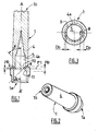
Figure 1 is a cross section view of an embodiment of the shield of the invention, -
Figure 2 is a perspective view of the shield offigure 1 , -
Figure 3 is a cross section view of the shield offigure 1 along transversal plane P1, -
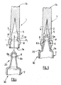
Figure 4 is a cross section view of the shield offigure 1 with a syringe hub ready to be assembled on the shield, -
Figure 5 is a cross section view of the shield offigure 4 once assembled on the syringe hub, -
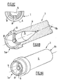
Figures 6A, 6B and 6C are respectively a perspective view, a cross section view according to the longitudinal axis of a perspective view and half of a bottom view of an alternative of the shield of the invention, -
Figures 7A, 7B and 7C are respectively a perspective view, a cross section view according to the longitudinal axis and half of a bottom view of an alternative of the shield of the invention, -
Figures 8A, 8B and 8C are respectively a perspective view, a cross section view according to the longitudinal axis and half of a bottom view of an alternative of the shield of the invention, -
Figure 9 is a cross section view of another alternative embodiment of the shield according to the invention contained in a shell, -
Figures 10A to 10H are cross section views similar tofigure 3 for alternative embodiments of the shield according to the invention, -
Figure 11 is a partial cross section view of an alternative embodiment of the shield according to the invention offigure 1 , and -
Figure 12 is a cross section view of the inner casing of the shield offigure 11 along transversal plane P1. - On
Figures 1 and 2 , is shown ashield 1 according to the invention having the general shape of cap, with an openproximal end 1 a, a closeddistal end 1b and alongitudinal wall 4 extending from saidproximal end 1 a to saiddistal end 1b and defining aninterior cavity 5. Thiscavity 5 is intended to receive at least part of a needle and needle hub (both shown onfigures 4 and 5 ). Theshield 1 offigure 1 comprises a first retainer forming anannular bead portion 9 defined on thewall 4 and extending from theinternal face 4a of saidwall 4 into thecavity 5. Theannular bead portion 9 is continuous and forms a continuous annular bead around the whole said cavity 5 (seefigure 3 ). - The
shield 1 also comprises a second retainer forming aprojection 8 extending from theannular bead portion 9 into thecavity 5. As is shown onfigure 1 , theannular bead 9 and theprojection 8 are located in the same transversal plane P1. -
Figure 3 is a cross section view of theshield 1 offigure 1 along the transversal plane P1 offigure 1 : onfigure 3 theinternal face 4a of thewall 4 is shown in dashes. As appears clearly on this figure, theannular bead portion 9 extends radially from saidinternal face 4a into saidcavity 5 on a first predetermined distance Db, and saidprojection 8 extends radially from saidinternal face 4a into saidinterior cavity 5 on a second predetermined distance Dp that is greater than said first predetermined distance Db. - Moreover, as appears from
figure 1 , theannular bead portion 9 extends longitudinally into saidcavity 5 on a first predetermined length Hb, and saidprojection 8 extends longitudinally into saidcavity 5 on a second predetermined length Hp that is greater than said first predetermined length Hb. - As shown on
figure 1 , theprojection 8 has adistal face 10 that forms an angle α with the longitudinal axis AA' of theshield 1, and aproximal face 11 that forms an angle β with said longitudinal axis AA'. The angle α preferably ranges from 20 to 40°. On the example shown, the angle α has a value of 30°. The angle β preferably ranges from 35 to 60°. On the example shown, the angle β has a value of 45°. - The
shield 1 offigure 1 is made of an elastically deformable material, for instance a thermoplastic elastomer. Theannular bead 9 and theprojection 8 are also made of an elastically deformable material, which may be identical or different from the material forming theshield 1. For example, theannular bead 9 and theprojection 8 of theshield 1 offigure 1 are made of thermoplastic elastomer. - In alternate embodiments of the invention, the
shield 1 comprises one or more additional annular beads and/or projections, in addition to the firstannular bead 9 and to thefirst projection 8 as described in reference withfigure 1 . The additional annular beads and projections may be identical or different in shape or in dimension from said firstannular bead 9 andfirst projection 8 respectively. They may be located in the same transversal plane as the firstannular bead 9 and/orprojection 8 or on the contrary in different transversal planes. -
Figures 6A to 8C are illustrative views of such alternative embodiments comprising additional projections. The references designating the same elements as infigure 1 have been maintained on all these figures. - On
figures 6A to 6C is shown an alternative embodiment of theshield 1 offigure 1 comprising a plurality ofprojections 8 regularly spaced from each other. In the example shown, theshield 1 comprises oneannular bead 9 and four (partially shown)projections 8, located in the same transversal plane as theannular bead 9. - On
figures 7A to 7C is shown an alternative embodiment of theshield 1 offigure 1 comprising a plurality ofprojections 8 regularly spaced from each other. In the example shown, theshield 1 comprises oneannular bead 9 and four (partially shown)projections 8, located in the same transversal plane as theannular bead 9. Theprojections 8 of theshield 1 offigures 7A to 7C have the shape of half a drop of water, the widest part of said drop of water facing thedistal end 1 b of theshield 1. - On
figures 8A to 8C is shown an alternative embodiment of theshield 1 offigure 1 comprising at least oneprojection 8 and at least oneannular bead 9. - Depending on the respective shape and number of annular beads and/or projections, said annular beads and/or projections may define for the cavity 5 a shape chosen in the group comprising a square, a triangle, an oblong format, a cross, a star.
- As will appear now from the description of
figures 4 and 5 , the firstannular bead 9, thefirst projection 8 and the optionally additional annular beads and projections are designed to be able to, resiliently and releasably, engage the same part of an assembly to secure saidshield 1 thereto. - On
figure 4 are shown theshield 1 offigure 1 and an administration device 30 (partially shown) comprising anassembly 20 and aneedle hub 6 located at the distal end of acontainer 7, partially shown, of saidadministration device 30. Theneedle hub 6 comprises a distal end forming abulging part 6a, which is separated from thecontainer 7 by a portion of reduceddiameter 6b of theneedle hub 6. Aneedle 2 is fixed at the distal end of the bulgingpart 6a. - As appears on
figure 4 , the diameter of the bulgingpart 6a is slightly larger than the diameter of thecavity 5 in the transversal plane P1. - In consequence, during the process of the
shield 1 assembly on theneedle hub 6 in order to protect theneedle 2, theannular bead 9 and theprojection 8 deform under the pressure exerted by the bulgingpart 6a. Once theshield 1 is in place, as shown onfigure 5 , theannular bead 9 and theprojection 8 come back in their rest state and are in contact and engaged with the same part of the assembly, that is to say the portion of reduceddiameter 6b of theneedle hub 6. Theshield 1 is therefore securely fixed to theneedle hub 6. - The combination of the
annular bead 9 and of theprojection 8 allows limiting the friction surface between thebulging part 6a of theneedle hub 6 and theshield 1. The generation of particles is therefore limited. In particular, because theproximal face 11 of theprojection 8 form an angle of 45° with the longitudinal axis AA' of the shield, the assembly of the shield on theneedle hub 6 is smooth and eased. In particular, because Dp is greater than Db (seefigure 3 ) theprojection 8 acts as a lever to amplify and ease the deformation of theannular bead 9 during the assembly of theshield 1. - For the same reason, the removal of the
shield 1 from theneedle hub 6 is facilitated and does not require an excessive force. In addition, the fact that thedistal face 10 of theprojection 8 forms an angle of 30° with the longitudinal axis AA' of theshield 1 facilitates the removal of theshield 1 from theneedle hub 6. When the user removes theshield 1 from theneedle hub 6, theannular bead 9 and theprojection 8 deform under the stress exerted by the bulgingpart 6a and then return to their normal state thanks to their inherent resilience. In this step of removal of theshield 1, theprojection 8 also acts as a lever to amplify and ease the deformation of theannular bead 9. - On
figure 9 is shown the shield offigure 1 contained in ashell 3. Theshell 3 is made of a rigid material, such as polypropylene. Theshell 3 is intended to protect theshield 1 from external shocks, ease theshield 1 handling and prevent the needle from piercing theshield 1. - On
figures 10A to 10H are shown cross section views similar tofigure 3 for alternative embodiments of theshield 1 of the invention where the projections define predetermined geometric shape. In particular theprojections 8 define for the cavity 5: - in
figure 10A , a shape of an oblong format, - in
figures 10B, 10E, and 10G , a shape similar to or substantially similar to a square, - in
figures 10C and 10D , a shape substantially similar to a triangle, - in
figure 10F , a shape substantially similar to a star, - in
figure 10H , a shape substantially similar to a cross. -
Figure 11 is a cross section view of an alternative embodiment of theshield 1 offigure 1 further comprising anouter casing 120 formed of a first material, and aninner casing 130 formed of a second material different from the said first material. The said first material and the said second material may show a different stiffness. The references designating the same elements as infigure 1 have been maintained infigure 11 . In the example shown onfigure 11 , theinner casing 130 defines theinterior cavity 5. Theshield 1 offigure 11 further comprises ahook 150 formed on theouter casing 120. Thehook 150 forms a bearing surface in contact with theinner casing 130. When theshield 1 is removed from the assembly (not shown), thehook 150 cooperates with theinner casing 130 so as to limit the stretching of the inner casing, in particular in regards to theouter casing 120 which is formed of a material different from the material forming theinner casing 130. - Indeed, when the
shield 1 is removed from the assembly, a negative pressure may be created in theinterior cavity 5, said negative pressure being likely to generate within said interior cavity the aspiration of the substance contained in the assembly. By limiting the stretching of theinner casing 130, thehook 150 forms an aspiration limiting means of the such created aspiration. -
Figure 12 is a cross section view of theinner casing 130 of theshield 1 offigure 11 along the transversal plane P1 offigure 11 : onfigure 12 , theinternal face 4a ofwall 4 is shown in dashes. As is clear from this figure, thebead portion 9 extends radially from saidinternal face 4a into saidcavity 5 on a first predetermined distance Db, and saidprojection 8 extends radially from saidinternal face 4a into saidinterior cavity 5 on a second predetermined distance Dp that is greater than said first predetermined distance Db. - The shield of the invention is an improvement of the needle shields of the prior art. Thanks to the shield of the invention, it is possible to efficiently protect a needle with a shield that may be assembled and/or removed on or from a syringe hub in a facilitated way and without generation of particles. Similarly, the shield of the invention can be efficiently used to protect the extremity of any kind of administration devices such as for example spraying devices and/or any kind of administration assemblies such as, for example, needle assembly, nozzle assembly.
Claims (20)
- A shield (1) for covering at least part of the extremity (6) of an administration device (30) or of an assembly (20), said shield (1) having an open proximal end (1a), a closed distal end (1b) and a longitudinal wall (4) extending from said proximal end (1a) to said distal end (1b) and defining an interior cavity (5) for receiving at least part of the extremity (6) of the administration device (30) or of the assembly (20), characterized in that it comprises at least a first retainer (9) defined on said wall (4) and extending into said cavity (5) and, at least one second retainer (8) defined on said wall (4) and extending into said cavity (5), said first retainer (9) and second retainer (8) being designed to be able to, resiliently and releasably, engage a part of said said extremity of the administration device (30) or assembly (20) to secure said shield (1) thereto, said first retainer (9) having at least its shape or one of its dimensions different from the shape or dimensions of said second retainer (8), said first retainer (9) and second retainer (8) resiliently and releasably engaging the same part (6b) of said extremity of the administration device (30) or assembly (20).
- A shield (1) according to claim 1, characterized in that said first retainer (9) and said second retainer (8) are located in the same transversal plane.
- A shield (1) according to claim 1 or 2, characterized in that said first retainer comprises at least a bead portion (9) that extends radially into said interior cavity (5) on a first predetermined distance Db, and said second retainer comprises at least a projection (8) that extends radially into said interior cavity (5) on a second predetermined distance Dp that is different than said first predetermined distance Db.
- A shield (1) according to one of claims 1 to 3, characterized in that said first retainer extends longitudinally into said interior cavity (5) on a first predetermined length Hb, and said second retainer extends longitudinally into said interior cavity (5) on a second predetermined length Hp that is different than said first predetermined length Hb.
- A shield (1) according to one of claims 1 to 4, characterized in that said first retainer or second retainer comprises a continuous annular bead (9).
- A shield (1) according to one of claims 1 to 5, characterized in that it comprises at least two first retainers (9) and/or two second retainers (8).
- A shield (1) according to claim 6, characterized in that each of the said two first retainers comprises a bead portion (9) and/or each of the said two second retainers comprises a projection (8), said bead portions (9) and said projections (8) being located in the same transversal planes and regularly spaced from each other.
- A shield (1) according to claim 6, characterized in that said each of the said two first retainers comprises a bead portion (9) and/or each of the said two second retainers comprises a projection (8), said bead portions (9) and said projections (8) being located in different transversal planes.
- A shield (1) according to one of claims 1 to 8, characterized in that at least one of said first retainer (9) or said second retainer (8) has a proximal face (11) forming a predetermined angle β with the longitudinal axis of said shield (1).
- A shield (1) according to claim 9, characterized in that said angle β ranges from 35° to 60°.
- A shield (1) according to one of claims 1 to 10, characterized in that at least one of said first retainer (9) or said second retainer (8) has a distal face (10) forming a predetermined angle α with the longitudinal axis of said shield (1).
- A shield (1) according to claim 11, characterized in that said angle α ranges from 20° to 40°.
- A shield (1) according to one of claims 1 to 12, characterized in that at least part of said shield (1) is made from an elastically deformable material and is contained within a shell (3) made at least in part from a rigid material.
- A shield (1) according to one of claims 1 to 13, characterized in that at least one of said first retainer (9) and/or said second retainer (8) have a cross-sectional shape of half drop of water of which widest part faces the distal end (1b) of said shield (1).
- A shield (1) according to one of claims 1 to 14, characterized in that said first retainer and/or second retainer (8, 9) define for said cavity (5) a predetermined geometric shape.
- A shield (1) according to claim 15, characterized in that said predetermined geometric shape is chosen in the group comprising a square, a triangle, an oblong format, a cross, a star.
- A shield (1) according to one of claims 1 to 16, characterized in that it further comprises:an outer casing (120) formed of a first material;an inner casing (130) formed of a second material different from the said first material, said inner casing (130) defining said interior cavity (5) for receiving, in an impermeable way, at least part of the extremity of the administration device (2) or of the assembly, andaspiration limiting means (150) designed for limiting the deformation of said interior cavity (5) when said shield (1) is separated from the assembly (20).
- A shield (1) according to claim 17, characterized in that said aspiration limiting means comprise bearing surfaces (150) designed for being in contact with said inner casing (130) and for cooperating with said inner casing (130) in order to limit the stretching of said inner casing (130) when said shield (1) is separated from the assembly (20).
- An assembly (20) for an administration device (30), said assembly (20) comprising at least an assembly hub for assembling said assembly on said administration device, characterized in that it further comprises a shield (1) according to at least claim 1.
- An administration device (30) comprising at least a container (7) and an extremity, characterized in that it further comprises a shield (1) according to at least claim 1 provided on said extremity.
Applications Claiming Priority (1)
| Application Number | Priority Date | Filing Date | Title |
|---|---|---|---|
| FR0701532A FR2913202A1 (en) | 2007-03-02 | 2007-03-02 | PROTECTION FOR COVERING THE END OF AN ADMINISTRATION DEVICE OR A SUBASSEMBLY, SUBASSEMBLY, AND ADMINISTRATION DEVICE |
Publications (1)
| Publication Number | Publication Date |
|---|---|
| EP1964588A1 true EP1964588A1 (en) | 2008-09-03 |
Family
ID=38188250
Family Applications (1)
| Application Number | Title | Priority Date | Filing Date |
|---|---|---|---|
| EP08356033A Withdrawn EP1964588A1 (en) | 2007-03-02 | 2008-03-03 | Shield for covering the extremity of an administration device or assembly, an administration assembly and an administration device |
Country Status (5)
| Country | Link |
|---|---|
| US (1) | US20080215013A1 (en) |
| EP (1) | EP1964588A1 (en) |
| JP (1) | JP2008229328A (en) |
| CN (1) | CN101301502A (en) |
| FR (1) | FR2913202A1 (en) |
Cited By (1)
| Publication number | Priority date | Publication date | Assignee | Title |
|---|---|---|---|---|
| FR3041263A1 (en) * | 2015-09-23 | 2017-03-24 | Aptar Stelmi Sas | DISPENSING ASSEMBLY COMPRISING A SYRINGE AND A NEEDLE PROTECTION DEVICE. |
Families Citing this family (29)
| Publication number | Priority date | Publication date | Assignee | Title |
|---|---|---|---|---|
| WO2006090118A1 (en) * | 2005-02-25 | 2006-08-31 | Salvus Technology Limited | Safety needle accessory |
| US9173997B2 (en) | 2007-10-02 | 2015-11-03 | Medimop Medical Projects Ltd. | External drug pump |
| US9656019B2 (en) | 2007-10-02 | 2017-05-23 | Medimop Medical Projects Ltd. | Apparatuses for securing components of a drug delivery system during transport and methods of using same |
| US10420880B2 (en) | 2007-10-02 | 2019-09-24 | West Pharma. Services IL, Ltd. | Key for securing components of a drug delivery system during assembly and/or transport and methods of using same |
| US8512295B2 (en) | 2010-08-19 | 2013-08-20 | West Pharmaceutical Services, Inc. | Rigid needle shield |
| WO2012043544A1 (en) * | 2010-09-29 | 2012-04-05 | テルモ株式会社 | Syringe with needle |
| USD655001S1 (en) | 2011-05-10 | 2012-02-28 | West Pharmaceutical Services Deutschland Gmbh & Co. Kg | Needle shield |
| JP5897203B2 (en) * | 2013-03-15 | 2016-03-30 | テルモ株式会社 | Syringe assembly, assembling method and assembling apparatus thereof, prefilled syringe using the same, and assembling method thereof |
| WO2014141470A1 (en) * | 2013-03-15 | 2014-09-18 | テルモ株式会社 | Syringe assembly, syringe assembly packaging, seal cap for outer cylinder, and pre-filled syringe |
| JP5976921B2 (en) * | 2013-03-15 | 2016-08-24 | テルモ株式会社 | Syringe assembly, syringe assembly package, and prefilled syringe |
| FR3011473B1 (en) * | 2013-10-08 | 2015-12-18 | Aptar Stelmi Sas | PROTECTIVE DEVICE FOR SYRINGE NEEDLE. |
| JP6479394B2 (en) * | 2014-10-02 | 2019-03-06 | テルモ株式会社 | Syringe assembly, syringe assembly package, and prefilled syringe |
| US10149943B2 (en) | 2015-05-29 | 2018-12-11 | West Pharma. Services IL, Ltd. | Linear rotation stabilizer for a telescoping syringe stopper driverdriving assembly |
| US10039913B2 (en) * | 2015-07-30 | 2018-08-07 | Carefusion 303, Inc. | Tamper-resistant cap |
| US10086145B2 (en) | 2015-09-22 | 2018-10-02 | West Pharma Services Il, Ltd. | Rotation resistant friction adapter for plunger driver of drug delivery device |
| US9987432B2 (en) | 2015-09-22 | 2018-06-05 | West Pharma. Services IL, Ltd. | Rotation resistant friction adapter for plunger driver of drug delivery device |
| US10576207B2 (en) | 2015-10-09 | 2020-03-03 | West Pharma. Services IL, Ltd. | Angled syringe patch injector |
| JP7017512B2 (en) | 2015-10-09 | 2022-02-08 | ウェスト ファーマ サービシーズ イスラエル リミテッド | Bending fluid path type accessories for filled fluid containers |
| WO2017089260A1 (en) * | 2015-11-27 | 2017-06-01 | Sanofi-Aventis Deutschland Gmbh | Component for an injection device, system, and method |
| EP3711793B1 (en) | 2016-01-21 | 2021-12-01 | West Pharma Services IL, Ltd. | A method of connecting a cartridge to an automatic injector |
| JP6542481B2 (en) | 2016-01-21 | 2019-07-10 | ウェスト ファーマ サービシーズ イスラエル リミテッド | system |
| US11311674B2 (en) | 2016-01-21 | 2022-04-26 | West Pharma. Services IL, Ltd. | Medicament delivery device comprising a visual indicator |
| US11389597B2 (en) | 2016-03-16 | 2022-07-19 | West Pharma. Services IL, Ltd. | Staged telescopic screw assembly having different visual indicators |
| US10376647B2 (en) | 2016-03-18 | 2019-08-13 | West Pharma. Services IL, Ltd. | Anti-rotation mechanism for telescopic screw assembly |
| EP3490643B1 (en) | 2016-08-01 | 2021-10-27 | West Pharma. Services Il, Ltd. | Anti-rotation cartridge pin |
| EP3978047B1 (en) | 2016-08-01 | 2023-08-23 | West Pharma Services IL, Ltd | Partial door closure prevention spring |
| EP3630226B1 (en) | 2017-05-30 | 2025-10-22 | West Pharma. Services Il, Ltd. | Modular drive train for wearable injector |
| WO2020216918A1 (en) * | 2019-04-26 | 2020-10-29 | Becton Dickinson France | Needle cover with undercut |
| EP4473990A1 (en) * | 2023-06-05 | 2024-12-11 | Becton Dickinson France | Syringe needle shield for minimizing needle corrosion |
Citations (4)
| Publication number | Priority date | Publication date | Assignee | Title |
|---|---|---|---|---|
| US3390759A (en) * | 1967-05-25 | 1968-07-02 | Becton Dickinson Co | Shield and hub for disposable needle |
| US3734080A (en) * | 1969-06-12 | 1973-05-22 | Johnson & Johnson | Blood collecting shut-off valve |
| FR2816848A1 (en) * | 2000-11-17 | 2002-05-24 | Rumpler Technologies | Protection device for syringe needle, comprises elastic longitudinal needle cap which includes annular bead at its lateral wall |
| EP1690562A1 (en) * | 2003-11-21 | 2006-08-16 | TSK Laboratory Japan | Syringe needle |
Family Cites Families (2)
| Publication number | Priority date | Publication date | Assignee | Title |
|---|---|---|---|---|
| US5385550A (en) * | 1994-03-29 | 1995-01-31 | Su; Chan-Ho | Needle protective means for prevention against stab and virus infection |
| DE19954373B4 (en) * | 1999-11-11 | 2011-01-27 | Helvoet Pharma Belgium N.V. | Protective cap for a cannula |
-
2007
- 2007-03-02 FR FR0701532A patent/FR2913202A1/en active Pending
-
2008
- 2008-02-27 US US12/038,197 patent/US20080215013A1/en not_active Abandoned
- 2008-02-29 CN CNA2008100966685A patent/CN101301502A/en active Pending
- 2008-03-03 EP EP08356033A patent/EP1964588A1/en not_active Withdrawn
- 2008-03-03 JP JP2008052530A patent/JP2008229328A/en active Pending
Patent Citations (5)
| Publication number | Priority date | Publication date | Assignee | Title |
|---|---|---|---|---|
| US3390759A (en) * | 1967-05-25 | 1968-07-02 | Becton Dickinson Co | Shield and hub for disposable needle |
| US3734080A (en) * | 1969-06-12 | 1973-05-22 | Johnson & Johnson | Blood collecting shut-off valve |
| FR2816848A1 (en) * | 2000-11-17 | 2002-05-24 | Rumpler Technologies | Protection device for syringe needle, comprises elastic longitudinal needle cap which includes annular bead at its lateral wall |
| US6719732B2 (en) | 2000-11-17 | 2004-04-13 | Rumpler Technologies | Protection device for syringe needle |
| EP1690562A1 (en) * | 2003-11-21 | 2006-08-16 | TSK Laboratory Japan | Syringe needle |
Cited By (5)
| Publication number | Priority date | Publication date | Assignee | Title |
|---|---|---|---|---|
| FR3041263A1 (en) * | 2015-09-23 | 2017-03-24 | Aptar Stelmi Sas | DISPENSING ASSEMBLY COMPRISING A SYRINGE AND A NEEDLE PROTECTION DEVICE. |
| WO2017051108A1 (en) * | 2015-09-23 | 2017-03-30 | Aptar Stelmi Sas | Dispensing assembly having a syringe and a needle guard |
| KR20180058761A (en) * | 2015-09-23 | 2018-06-01 | 압따르 스뗄미 에스아에스 | Dispensing assembly including needle and needle protection device |
| JP2018528014A (en) * | 2015-09-23 | 2018-09-27 | アプター ステルミ エスアーエスAptar Stelmi Sas | Dosing assembly with syringe and needle protection device |
| US11040148B2 (en) | 2015-09-23 | 2021-06-22 | Aptar Stelmi Sas | Dispensing assembly having a syringe and a needle guard |
Also Published As
| Publication number | Publication date |
|---|---|
| CN101301502A (en) | 2008-11-12 |
| JP2008229328A (en) | 2008-10-02 |
| US20080215013A1 (en) | 2008-09-04 |
| FR2913202A1 (en) | 2008-09-05 |
Similar Documents
| Publication | Publication Date | Title |
|---|---|---|
| US20080215013A1 (en) | Shield for covering the extremity of an administration device or assembly, an administration assembly and an administration device | |
| EP1964586A1 (en) | Shield for covering the extremity of an administration device or assembly, an assembly and an administration device | |
| JP6302005B2 (en) | Needle protection device | |
| JP5849360B2 (en) | Medical needle safety device | |
| EP2574355A1 (en) | Package for a medicament delivery device | |
| US4986818A (en) | Syringe assembly | |
| KR101603139B1 (en) | Syringe with recessed nose and protective guard for use with frontal attachments | |
| US4964866A (en) | Needle sheath assembly | |
| US4929232A (en) | Syringe having tamper evidence features | |
| JP5969984B2 (en) | Needle safety device for medical equipment | |
| US20110213304A1 (en) | Retractable needle assembly utilizing a standard interface and syringe utilizing the same | |
| WO2015007857A1 (en) | Needle shield remover | |
| US10973986B2 (en) | Protective device for a syringe needle | |
| JP2013519415A (en) | Medical needle cover device | |
| US20120123334A1 (en) | Pen needle with quick release and/or removal system | |
| US5554129A (en) | Safety cap and hub for medical instruments | |
| US5352208A (en) | Safe non-reusable hypodermic syringe | |
| WO2021001450A1 (en) | Blood collectable peripheral intravenous catheter assemblies and related methods | |
| JP2026501448A (en) | Improvements in medical needle cover devices | |
| US9446203B2 (en) | Needle hub and disposal device for single-use needle assemblies | |
| EP4527434A1 (en) | Syringe needle shield with tamper evidence feature and consistent needle pull-out force | |
| JP3099968U (en) | Cap to protect injection needle | |
| US20140200514A1 (en) | Single-use needle assembly and storage device |
Legal Events
| Date | Code | Title | Description |
|---|---|---|---|
| PUAI | Public reference made under article 153(3) epc to a published international application that has entered the european phase |
Free format text: ORIGINAL CODE: 0009012 |
|
| AK | Designated contracting states |
Kind code of ref document: A1 Designated state(s): AT BE BG CH CY CZ DE DK EE ES FI FR GB GR HR HU IE IS IT LI LT LU LV MC MT NL NO PL PT RO SE SI SK TR |
|
| AX | Request for extension of the european patent |
Extension state: AL BA MK RS |
|
| 17P | Request for examination filed |
Effective date: 20090210 |
|
| AKX | Designation fees paid |
Designated state(s): AT BE BG CH CY CZ DE DK EE ES FI FR GB GR HR HU IE IS IT LI LT LU LV MC MT NL NO PL PT RO SE SI SK TR |
|
| STAA | Information on the status of an ep patent application or granted ep patent |
Free format text: STATUS: THE APPLICATION IS DEEMED TO BE WITHDRAWN |
|
| 18D | Application deemed to be withdrawn |
Effective date: 20101001 |