EP1964148B1 - Fluorine based cleaning of an ion source - Google Patents
Fluorine based cleaning of an ion source Download PDFInfo
- Publication number
- EP1964148B1 EP1964148B1 EP06848020A EP06848020A EP1964148B1 EP 1964148 B1 EP1964148 B1 EP 1964148B1 EP 06848020 A EP06848020 A EP 06848020A EP 06848020 A EP06848020 A EP 06848020A EP 1964148 B1 EP1964148 B1 EP 1964148B1
- Authority
- EP
- European Patent Office
- Prior art keywords
- ion source
- source
- ion
- aperture
- electrode
- Prior art date
- Legal status (The legal status is an assumption and is not a legal conclusion. Google has not performed a legal analysis and makes no representation as to the accuracy of the status listed.)
- Not-in-force
Links
- 238000004140 cleaning Methods 0.000 title claims description 46
- YCKRFDGAMUMZLT-UHFFFAOYSA-N Fluorine atom Chemical compound [F] YCKRFDGAMUMZLT-UHFFFAOYSA-N 0.000 title claims description 42
- 229910052731 fluorine Inorganic materials 0.000 title claims description 27
- 239000011737 fluorine Substances 0.000 title claims description 26
- 230000007246 mechanism Effects 0.000 claims description 47
- 238000010884 ion-beam technique Methods 0.000 claims description 36
- 238000000034 method Methods 0.000 claims description 23
- 238000005468 ion implantation Methods 0.000 claims description 14
- 230000008569 process Effects 0.000 claims description 9
- 150000002500 ions Chemical class 0.000 description 135
- 230000001629 suppression Effects 0.000 description 29
- 239000011538 cleaning material Substances 0.000 description 26
- 239000007789 gas Substances 0.000 description 20
- 239000000463 material Substances 0.000 description 14
- 239000002019 doping agent Substances 0.000 description 11
- 238000010586 diagram Methods 0.000 description 8
- 238000000605 extraction Methods 0.000 description 8
- 235000012431 wafers Nutrition 0.000 description 8
- 230000001133 acceleration Effects 0.000 description 7
- 230000000903 blocking effect Effects 0.000 description 7
- 230000005684 electric field Effects 0.000 description 6
- 239000007787 solid Substances 0.000 description 6
- 238000002513 implantation Methods 0.000 description 5
- 239000004065 semiconductor Substances 0.000 description 4
- ZOXJGFHDIHLPTG-UHFFFAOYSA-N Boron Chemical compound [B] ZOXJGFHDIHLPTG-UHFFFAOYSA-N 0.000 description 3
- 229910052785 arsenic Inorganic materials 0.000 description 3
- RQNWIZPPADIBDY-UHFFFAOYSA-N arsenic atom Chemical compound [As] RQNWIZPPADIBDY-UHFFFAOYSA-N 0.000 description 3
- 125000004429 atom Chemical group 0.000 description 3
- 229910052796 boron Inorganic materials 0.000 description 3
- 238000006243 chemical reaction Methods 0.000 description 3
- 238000010494 dissociation reaction Methods 0.000 description 3
- 230000005593 dissociations Effects 0.000 description 3
- IJGRMHOSHXDMSA-UHFFFAOYSA-N Atomic nitrogen Chemical compound N#N IJGRMHOSHXDMSA-UHFFFAOYSA-N 0.000 description 2
- -1 NF3 Chemical class 0.000 description 2
- XYFCBTPGUUZFHI-UHFFFAOYSA-N Phosphine Chemical compound P XYFCBTPGUUZFHI-UHFFFAOYSA-N 0.000 description 2
- 230000015572 biosynthetic process Effects 0.000 description 2
- 150000002222 fluorine compounds Chemical class 0.000 description 2
- 125000001153 fluoro group Chemical group F* 0.000 description 2
- BHEPBYXIRTUNPN-UHFFFAOYSA-N hydridophosphorus(.) (triplet) Chemical compound [PH] BHEPBYXIRTUNPN-UHFFFAOYSA-N 0.000 description 2
- 238000011065 in-situ storage Methods 0.000 description 2
- 239000007788 liquid Substances 0.000 description 2
- 230000007935 neutral effect Effects 0.000 description 2
- 239000002245 particle Substances 0.000 description 2
- 238000005389 semiconductor device fabrication Methods 0.000 description 2
- 231100000331 toxic Toxicity 0.000 description 2
- 230000002588 toxic effect Effects 0.000 description 2
- OAICVXFJPJFONN-UHFFFAOYSA-N Phosphorus Chemical compound [P] OAICVXFJPJFONN-UHFFFAOYSA-N 0.000 description 1
- 230000002411 adverse Effects 0.000 description 1
- 230000004075 alteration Effects 0.000 description 1
- 230000000712 assembly Effects 0.000 description 1
- 238000000429 assembly Methods 0.000 description 1
- 150000001875 compounds Chemical class 0.000 description 1
- 230000006378 damage Effects 0.000 description 1
- 230000003247 decreasing effect Effects 0.000 description 1
- 230000001419 dependent effect Effects 0.000 description 1
- 230000000694 effects Effects 0.000 description 1
- 229910052736 halogen Inorganic materials 0.000 description 1
- 150000002367 halogens Chemical class 0.000 description 1
- 239000007943 implant Substances 0.000 description 1
- 238000007689 inspection Methods 0.000 description 1
- 230000003993 interaction Effects 0.000 description 1
- 239000000203 mixture Substances 0.000 description 1
- 230000004048 modification Effects 0.000 description 1
- 238000012986 modification Methods 0.000 description 1
- 229910052757 nitrogen Inorganic materials 0.000 description 1
- 229910052698 phosphorus Inorganic materials 0.000 description 1
- 239000011574 phosphorus Substances 0.000 description 1
- 230000002035 prolonged effect Effects 0.000 description 1
- 238000005215 recombination Methods 0.000 description 1
- 230000006798 recombination Effects 0.000 description 1
- 239000000126 substance Substances 0.000 description 1
Images


Classifications
-
- H—ELECTRICITY
- H01—ELECTRIC ELEMENTS
- H01J—ELECTRIC DISCHARGE TUBES OR DISCHARGE LAMPS
- H01J37/00—Discharge tubes with provision for introducing objects or material to be exposed to the discharge, e.g. for the purpose of examination or processing thereof
- H01J37/30—Electron-beam or ion-beam tubes for localised treatment of objects
- H01J37/317—Electron-beam or ion-beam tubes for localised treatment of objects for changing properties of the objects or for applying thin layers thereon, e.g. for ion implantation
- H01J37/3171—Electron-beam or ion-beam tubes for localised treatment of objects for changing properties of the objects or for applying thin layers thereon, e.g. for ion implantation for ion implantation
-
- B—PERFORMING OPERATIONS; TRANSPORTING
- B08—CLEANING
- B08B—CLEANING IN GENERAL; PREVENTION OF FOULING IN GENERAL
- B08B7/00—Cleaning by methods not provided for in a single other subclass or a single group in this subclass
- B08B7/0035—Cleaning by methods not provided for in a single other subclass or a single group in this subclass by radiant energy, e.g. UV, laser, light beam or the like
-
- H—ELECTRICITY
- H01—ELECTRIC ELEMENTS
- H01J—ELECTRIC DISCHARGE TUBES OR DISCHARGE LAMPS
- H01J27/00—Ion beam tubes
- H01J27/02—Ion sources; Ion guns
- H01J27/022—Details
-
- H—ELECTRICITY
- H01—ELECTRIC ELEMENTS
- H01J—ELECTRIC DISCHARGE TUBES OR DISCHARGE LAMPS
- H01J37/00—Discharge tubes with provision for introducing objects or material to be exposed to the discharge, e.g. for the purpose of examination or processing thereof
- H01J37/02—Details
- H01J37/04—Arrangements of electrodes and associated parts for generating or controlling the discharge, e.g. electron-optical arrangement or ion-optical arrangement
- H01J37/08—Ion sources; Ion guns
-
- H—ELECTRICITY
- H01—ELECTRIC ELEMENTS
- H01J—ELECTRIC DISCHARGE TUBES OR DISCHARGE LAMPS
- H01J37/00—Discharge tubes with provision for introducing objects or material to be exposed to the discharge, e.g. for the purpose of examination or processing thereof
- H01J37/30—Electron-beam or ion-beam tubes for localised treatment of objects
-
- H—ELECTRICITY
- H01—ELECTRIC ELEMENTS
- H01J—ELECTRIC DISCHARGE TUBES OR DISCHARGE LAMPS
- H01J37/00—Discharge tubes with provision for introducing objects or material to be exposed to the discharge, e.g. for the purpose of examination or processing thereof
- H01J37/30—Electron-beam or ion-beam tubes for localised treatment of objects
- H01J37/304—Controlling tubes by information coming from the objects or from the beam, e.g. correction signals
-
- H—ELECTRICITY
- H01—ELECTRIC ELEMENTS
- H01J—ELECTRIC DISCHARGE TUBES OR DISCHARGE LAMPS
- H01J37/00—Discharge tubes with provision for introducing objects or material to be exposed to the discharge, e.g. for the purpose of examination or processing thereof
- H01J37/32—Gas-filled discharge tubes
- H01J37/32431—Constructional details of the reactor
- H01J37/32798—Further details of plasma apparatus not provided for in groups H01J37/3244 - H01J37/32788; special provisions for cleaning or maintenance of the apparatus
-
- H—ELECTRICITY
- H01—ELECTRIC ELEMENTS
- H01J—ELECTRIC DISCHARGE TUBES OR DISCHARGE LAMPS
- H01J37/00—Discharge tubes with provision for introducing objects or material to be exposed to the discharge, e.g. for the purpose of examination or processing thereof
- H01J37/32—Gas-filled discharge tubes
- H01J37/32431—Constructional details of the reactor
- H01J37/32798—Further details of plasma apparatus not provided for in groups H01J37/3244 - H01J37/32788; special provisions for cleaning or maintenance of the apparatus
- H01J37/32853—Hygiene
- H01J37/32862—In situ cleaning of vessels and/or internal parts
-
- H—ELECTRICITY
- H01—ELECTRIC ELEMENTS
- H01J—ELECTRIC DISCHARGE TUBES OR DISCHARGE LAMPS
- H01J37/00—Discharge tubes with provision for introducing objects or material to be exposed to the discharge, e.g. for the purpose of examination or processing thereof
- H01J37/32—Gas-filled discharge tubes
- H01J37/34—Gas-filled discharge tubes operating with cathodic sputtering
- H01J37/3488—Constructional details of particle beam apparatus not otherwise provided for, e.g. arrangement, mounting, housing, environment; special provisions for cleaning or maintenance of the apparatus
-
- H—ELECTRICITY
- H01—ELECTRIC ELEMENTS
- H01J—ELECTRIC DISCHARGE TUBES OR DISCHARGE LAMPS
- H01J2237/00—Discharge tubes exposing object to beam, e.g. for analysis treatment, etching, imaging
- H01J2237/02—Details
- H01J2237/022—Avoiding or removing foreign or contaminating particles, debris or deposits on sample or tube
-
- H—ELECTRICITY
- H01—ELECTRIC ELEMENTS
- H01J—ELECTRIC DISCHARGE TUBES OR DISCHARGE LAMPS
- H01J2237/00—Discharge tubes exposing object to beam, e.g. for analysis treatment, etching, imaging
- H01J2237/30—Electron or ion beam tubes for processing objects
- H01J2237/317—Processing objects on a microscale
- H01J2237/31701—Ion implantation
- H01J2237/31705—Impurity or contaminant control
Definitions
- the present invention relates generally to semiconductor device fabrication and ion implantation, and more particularly, cleaning ion sources of ion implantation systems using fluorine.
- Ion implantation is a physical process that is employed in semiconductor device fabrication to selectively implant dopant into semiconductor and/or wafer material. Thus, the act of implanting does not rely on a chemical interaction between a dopant and semiconductor material.
- dopant atoms/molecules are ionized, accelerated, formed into a beam, analyzed, and swept across a wafer, or the wafer is swept through the beam.
- the dopant ions physically bombard the wafer, enter the surface and come to rest below the surface, at a depth related to their energy.
- Ion implanters or ion implantation systems typically include an ion source including an ionization chamber for ionizing a neutral gas from gaseous feed material or from vapor generated from a solid or liquid feed material to produce a collection of charged particles, i . e . ions and electrons, hereinafter referred to as a plasma.
- Ions are extracted from the ion source plasma by creating an electric field between the source plasma and an electrode, or a series of electrodes, to form an ion beam. The beam travels through specially shaped apertures in each of the electrodes.
- Typical beam extraction systems are either 3 or 4 electrode systems, although other variations are possible, including very extended systems where final beam deceleration is accomplished in the proximity of the wafer.
- a standard three electrode system typically comprises a first electrode, the so-called plasma electrode, or arc slit electrode, or ionization chamber electrode, which may be electrically biased at the same large positive voltage as the ion source. This potential determines the beam energy.
- a second electrode, the so-called suppression electrode is at a moderate negative voltage to prevent electrons from streaming back to the source chamber.
- a third and final electrode, the so-called ground electrode is at ground potential. The extracting electric field is determined by the potential difference between the ionization chamber electrode and the suppression electrode, the details of their shapes, and the distance there between.
- ion source When the ion source is operated with a molecular fill gas or vapor, other species in addition to the desired species for implantation are produced. Some of these species may have very low vapor pressures, and as a result condense on the interior surfaces of the source. These solid deposits may interfere with ion source operation over time, for example by changing the electrical characteristics of the walls or partially blocking the ion source electrode aperture, thereby reducing the available ion current.
- One method of removing these deposits is the time consuming process of removing the ion source from the system and physically cleaning the source.
- Another method would be to clean the source in situ by flowing a highly reactive gas through the source, where the gas species is chosen such that the reaction with the deposited material results in a high vapor pressure material which leaves the ion source as a gas and is pumped out of the system.
- a species with the desired characteristics is atomic fluorine, typically generated by the dissociation of NF 3 in a plasma.
- relatively large flow rates of the reactive gas are required to perform proper cleaning of the ion source surfaces. The relatively large flow rates adversely effect both tool cost and cost of operation.
- WO 05/059942 discloses that the service lifetime of an ion source is enhanced or prolonged by the source having provisions for in-situ etch cleaning of the ion source and of an extraction electrode, using reactive halogen gases, and by having features that extend the service duration between cleanings.
- the latter include accurate vapor flow control, accurate focusing of the ion beam optics, and thermal control of the extraction electrode that prevents formation of deposits or prevents electrode destruction.
- An apparatus comprises of an ion source for generating dopant ions for semiconductor wafer processing is coupled to a remote plasma source which delivers F or Cl ions to the first ion source for the purpose of cleaning deposits in the first ion source and the extraction electrode.
- the present invention facilitates ion implantation processes by performing cleanings of surfaces within ion sources by using atomic fluorine as a cleaning material.
- the cleanings can be performed with lower flow rates than conventional fluorine based cleanings by employing a throttle mechanism that at least partly traps fluorine within the ion source to facilitate cleaning of the ion source.
- an ion implantation system comprising: an ion source comprising interior surfaces and a source aperture; a deposit cleaning system that employs a throttle mechanism to remove deposits from the surfaces and the source aperture of the ion source, wherein the deposit cleaning system comprises: a fluorine source for supplying fluorine to the ion source; a throttle mechanism that mitigates loss of fluorine through the source aperture that comprises a movable electrode that includes a throttle region, wherein the movable electrode is positioned so that the throttle region at least partially covers the source aperture; and a controller that controls the supply and flow rate from the fluorine source to the ion source and that controls the positioning of the throttle mechanism; a beam line assembly that receives the ion beam from the ion and processes the ion beam; and a target location that receives the ion beam from the beam line assembly.
- Atomic fluorine fluorine radicals
- a fluorine compound such as NF 3
- Atomic fluorine is generated by the dissociation of NF 3 in a plasma.
- the plasma may be remote from the surfaces to be cleaned and the dissociated gas transported to the surfaces.
- the atomic fluorine can be formed or generated within an ion source to clean the surfaces.
- NF 3 large flow rates of NF 3 are required, for example, due to recombination of atomic fluorine in a region between a remote source and the ion source surfaces to be cleaned and uncombined atomic fluorine exiting the ion source through the source aperture.
- the present invention employs a throttle mechanism at or near a source aperture of an ion source.
- the throttle mechanism reduces quantities of atomic fluorine lost through the aperture and directs fluorine atoms back toward surfaces to be cleaned within the source. Additionally, the throttle mechanism can direct atoms to outer edges of the aperture, thereby providing enhanced cleaning of these surfaces. For normal ion source operation, the throttle mechanism is positioned so as to not interfere.
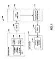
- FIG. 1 an ion implantation system 100 suitable for implementing one or more aspects of the present invention is depicted in block diagram form.
- the system 100 includes an ion source 102 for producing an ion beam 104 along a beam path.
- the ion beam source 102 includes, for example, a plasma source 106 with an associated power source 108.
- the plasma source 106 may, for example, comprise a relatively long plasma confinement chamber from which an ion beam is extracted and accelerated.
- the ion source 102 includes a fluorine based cleaning system 122 that can remove these deposits from interior surfaces of the ion source.
- the fluorine based cleaning system 122 flows the highly reactive gas fluorine through the ion source 102, such that the reaction with the deposited material results in a high vapor pressure material which leaves the ion source 102 as a gas and is pumped out of the system.
- the cleaning system 122 also includes a throttle mechanism that limits or prevents un-reacted components of the reactive gas from leaving the ion source 102 without reacting with the deposits. As a result of employing the throttle mechanism, relatively lower flow rates can be employed for the reactive gas than in conventional cleaning systems to obtain suitable cleaning of surfaces within the ion source 102.
- the cleaning system 122 can be engaged periodically or as desired in order to reduce or remove the deposits from surfaces within the ion source 102.
- the throttle mechanism of the cleaning system 122 is typically disengaged so as to allow passage of the ion beam through the ion source aperture. Otherwise, the throttle mechanism can be engaged to mitigate un-reacted components of the reactive gas from leaving the ion source 102 through the aperture.
- a beam line assembly 110 is provided downstream of the ion source 102 to receive the beam 104 there from.
- the beam line assembly 110 includes a mass analyzer 112, an acceleration structure 114, which may include, for example, one or more gaps.
- the beam line assembly 110 is situated along the path to receive the beam 104.
- the mass analyzer 112 includes a field generating component, such as a magnet (not shown), and operates to provide a field across the beam path so as to deflect ions from the ion beam 104 at varying trajectories according to mass ( e.g ., charge to mass ratio). Ions traveling through the magnetic field experience a force which directs individual ions of a desired mass along the beam path and which deflects ions of undesired mass away from the beam path.
- the acceleration gap or gaps within the acceleration structure 114 are operable to accelerate and/or decelerate ions within the beam to achieve a desired depth of implantation in a workpiece. Accordingly, it will be appreciated that while the terms accelerator and/or acceleration gap may be utilized herein in describing one or more aspects of the present invention, such terms are not intended to be construed narrowly so as to be limited to a literal interpretation of acceleration, but are to be construed broadly so as to include, among other things, deceleration as well as changes in direction. It will be further appreciated that acceleration/deceleration means may be applied before as well as after the magnetic analysis by the mass analyzer 112. Additionally, the acceleration structure 114 can also be part of the ion source, in some aspects, and omitted as part of the beam line assembly.
- An end station 118 is also provided in the system 100 to ion beam 104 from the beamline assembly 110.
- the end station 118 supports one or more workpieces such as semiconductor wafers (not shown) along the beam path for implantation using the mass analyzed ion beam 104.
- the end station 118 includes a target scanning system 120 for translating or scanning one or more target workpieces and the ion beam 104 relative to one another.
- the target scanning system 120 may provide for batch or serial implantation, for example, as may be desired under given circumstances, operating parameters and/or objectives.
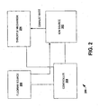
- Fig. 2 is a block diagram of a fluorine based cleaning system 200 in accordance with an aspect of the present invention.
- the system 200 is employed to remove deposits from interior surfaces, including apertures, of an ion source 202 with a relatively reduced flow rate.
- the system 200 operates on an ion source 202 and includes a throttle mechanism 204, a fluorine source 206, and a controller 208.
- the ion source 202 may include an ionization chamber for ionizing a neutral gas from gaseous feed material or from vapor generated from a solid or liquid feed material to produce a collection of charged particles, i . e . ions and electrons, hereinafter referred to as a plasma. Ions are extracted from the ion source plasma by creating an electric field between the source plasma and an electrode, or a series of electrodes (not shown), to form an ion beam. The beam travels through specially shaped apertures in each of the electrodes.
- Typical beam extraction systems are either 3 or 4 electrode systems, although other variations are possible, including very extended systems where final beam deceleration is accomplished in the proximity of the wafer.
- a standard three electrode system typically comprises a first electrode, the so-called plasma electrode, or arc slit electrode, or ionization chamber electrode, which may be electrically biased at the same large positive voltage as the ion source. This potential determines the beam energy.
- a second electrode, the so-called suppression electrode is at a moderate negative voltage to prevent electrons from streaming back to the source chamber.
- a third and final electrode, the so-called ground electrode is at ground potential. The extracting electric field is determined by the potential difference between the ionization chamber electrode and the suppression electrode, the details of their shapes, and the distance there between.
- phosphorous (P) deposits may form on surfaces within the ion source 202 when phosphine (PH 3 ) is run through the ion source 202.
- the fluorine source 206 maintains and provides fluorine to the ion source 202 that reacts with and removes deposits formed on the surfaces within the ion source 202.
- the fluorine source 206 can provide the fluorine as atomic fluorine (fluorine radicals) so as to clean surfaces of the ion source 202.
- pure fluorine is toxic and difficult to handle.
- a fluorine compound such as NF 3
- Atomic fluorine is generated by the dissociation of NF 3 in a plasma. The result of this disassociation is that the NF 3 will disassociate into nitrogen and fluorine atoms, which can then react with the deposited materials.
- the plasma may be remote from the surfaces to be cleaned and the dissociated gas transported to the surfaces.
- the atomic fluorine can be formed or generated within the ion source 202 to clean the surfaces.
- the throttle mechanism 204 prevents or mitigates un-reacted atomic fluorine from exiting the ion source 202.
- the throttle mechanism 204 may comprise, for example, a blocking member (not shown) that at least partially covers the ion source's aperture. As a result, un-reacted atomic fluorine is at least partially prevented from exiting the ion source 202 via the aperture.
- the throttle mechanism 204 may comprise a movable suppression electrode (not shown) that at least partially covers the ion source's aperture during cleaning but is moved during normal operation to allow and generate passage of an ion beam.
- the controller 208 controls operation of the ion source 206 and the throttle mechanism 204.
- the controller 208 controls flow rates and/or composition of the cleaning material provided to the ion source 202 as well as starting and duration of cleaning operations.
- the controller 208 also controls engagement of the throttle mechanism 204.
- the throttle mechanism 204 is engaged during cleaning operations or cleaning cycles and disengaged during normal operations.
- the controller 208 can also control the rate of exhaust via the ion source's aperture. For example, the controller 208 can cause the throttle mechanism 204 to completely cover the aperture or, cover a selected percentage of the aperture in order to provide a selected exhaust rate.
- controller 208 can, in some, but not necessarily all aspects, detect and/or measure deposit buildup on surfaces within the ion source 202. Based on the measured and/or detected deposit buildup, the controller 208 can selectively initiate or refrain from performing cleaning cycles or operations.
- Fig. 3 is a diagram illustrating an ion source deposit cleaning system 300, which is not covered by the present invention.
- the system 300 employs a movable throttle member 308 that can mitigate or prevent unreacted cleaning components from exiting an ion source 302 during cleaning operations or cycles.
- the ion source 302 is operable to produce an ion beam comprising one or more selected dopants.
- the ion beam source 302 can include, for example, a plasma source with an associated power source.
- the plasma source may, for example, comprise a relatively long plasma confinement chamber from which an ion beam is extracted.
- the ion beam is extracted or formed through an aperture 306 by employing electrodes as described above.
- Dopants and/or dopant materials can deposit and/or form on surfaces, including the aperture 306, within the ion source 302 during operation or generation of ion beams.
- An inlet or valve 304 provides a cleaning material, such as NF3 or atomic fluorine to the ion source 302.
- the cleaning material reacts with the formed deposits to create a gas, which can then be exhausted from the ion source 302.
- the throttle member 308 acts as a throttle mechanism to limit or mitigate unreacted cleaning material from exiting the ion source 302 via the aperture 306.
- the throttle member 308 is depicted as having a curved upper portion that facilitates returning unreacted cleaning material to the ion source 302 and a lower portion or arm. It is noted that alternate aspects of the invention include throttle members of varying shapes that partially block the aperture 306 and mitigate unreacted cleaning material from exiting the ion source 302.
- the throttle member 308 in this example, has an engaged position 310 and a disengaged position 312.
- the engaged position 310 also referred to as a cleaning position
- the member 308 is positioned so as to at least partially cover the aperture 306 and mitigate exiting of unreacted cleaning material from the ion source 302. It is noted, that while in the engaged position 310, ion beam generation is generally prevented.
- the member 308 is positioned away from the aperture 306 by a distance or gap referred to as a throttle gap 314. Increasing this distance allows more exhaust from the ion source 302 and decreasing this distance allows less exhaust from the ion source 302.
- the member 308 In the disengaged position, the member 308 is positioned away from the ion source aperture 306 so as to permit normal ion beam generation to continue.
- the member 308 is depicted as being pivoted or rotated about the lower portion or arm in order to move the member 308 away from the aperture 306.
- other techniques can be employed to properly move the member 308 and permit normal ion beam generation, such as sliding the member308 above or below the shown engaged position 310.
- the cleaning material can still be supplied with the member 308 in the disengaged position 312, but the flow of the cleaning material is typically required to be greater.
- Fig. 4A is a top view of a throttle mechanism 400 in accordance with an aspect of the present invention.
- the throttle mechanism 400 employs a suppression electrode 402 to limit or mitigate unreacted cleaning material from exiting an ion source via an aperture.
- the throttle mechanism 400 can move or slide along a side axis in order to controllably throttle the aperture of the ion source.
- the throttle mechanism 400 includes the suppression electrode 402 and a manipulator arm 404.
- the suppression electrode 402 operates in conjunction with a plasma electrode located within the ion source (not shown) and a ground electrode (not shown) positioned downstream to extract and form an ion beam having a desired shape, current, and the like during beam generation.
- the manipulator arm 404 holds and supports the electrode 402.
- a suppression aperture 406 is defined on the electrode 402 through which the ion beam is formed and passes through.
- the electrode 402 is positioned along the side axis such that the aperture is at or about the aperture of the ion source.
- the suppression electrode 402 also includes a throttle portion 408 defined or formed on/in the electrode that can mitigate or limit unreacted cleaning material from exiting the ion source during cleaning operations or cycles.
- the throttle portion 408 can, for example, be a solid portion of the electrode 402. Alternately, the throttle portion 408 can be formed into the electrode 402 with a defined profile and/or formed of other materials.
- mechanism 400 described in Fig. 4 is merely one example of a suitable electrode based throttle mechanism in accordance with the present invention. It is appreciated, for example, that a ground electrode can be employed in a similar fashion to limit exiting of unreacted cleaning materials.
- Fig. 4B is a side view of the throttle mechanism 400 of Fig. 4A in accordance with an aspect of the present invention. This view illustrates an ion source 410 along with the throttle mechanism 400 in an engaged position 416 or a disengaged position 418.
- the throttle mechanism 400 employs the suppression electrode 402 to limit or mitigate unreacted cleaning material from exiting an ion source via an aperture.
- the ion source 410 includes a source aperture 412 through which dopants or ions pass through to thereby form as an ion beam.
- extraction and/or formation of the ion beam utilizes the suppression electrode 402 and a ground electrode 414, both of which are supported as a group by the arm 404.
- the suppression aperture 406 is defined on the electrode 402 through which the ion beam is formed and passes through.
- the electrode 402 is positioned along the side axis such that the aperture 406 is at or about the aperture of the ion source as shown in the disengaged position 418.
- the throttle portion 408 of the suppression electrode 402 prevents or mitigates cleaning material from exiting the ion source 410 via the source aperture 412 by at least partially blocking the source aperture 412.
- the throttle portion 408 is positioned about the source aperture 412 during cleaning operations or cycles as shown in the engaged position 416.
- the throttle portion 408 is depicted, in this example, as being flat with respect to the suppression electrode 402.
- the suppression aperture 406 is positioned a gap distance 420 away from the ion source aperture 412.
- the electrode 402 is in the throttle disengaged position 418 and the gap distance 420 is selected as a function of desired beam generation characteristics, such as beam current, size, shape, and the like.
- the electrode 402 is arranged in the engaged position 416 and the gap distance 420 can be selected at least partially according to a desired exhaust rate or cleaning material containment rate.
- Fig. 4C is another side view of a throttle mechanism 400 in accordance with an aspect of the present invention. This view is similar to that shown in Fig. 4B , but with a different profile for the throttle portion 408. The other components are identical to those in Fig. 4B , which can be referenced for further description.
- the throttle portion 408, in this example, has a curvature or profile that further facilitates blocking cleaning material. This profile tends to redirect exiting cleaning material back through the ion source aperture 412.
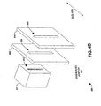
- Fig. 4D is a perspective view of the throttle mechanism 400 of Fig. 4A in accordance with an aspect of the present invention. The view depicts the suppression electrode 402 located in the throttle disengaged position 418 to permit ion beam generation.
- the view includes the ion source 410 and the source aperture 412.
- the suppression electrode 402 is located downstream of the ion source and the ground electrode 414 is located downstream of the suppression electrode 402.
- dopants or ions pass from the ion source 410 via the source aperture 412, through the aperture 406 of the suppression electrode 402 and through an aperture of the ground electrode 414.
- the suppression electrode 402 can be moved along the side axis so that the throttle region 408 of the suppression electrode is positioned about the ion source aperture 412 instead of the aperture 406 being positioned about the ion source aperture 412 for cleaning operations or cycles.
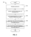
- Fig. 5 is a flow diagram illustrating a method 500 of cleaning deposits from surfaces within an ion source in accordance with an aspect of the present invention.
- the method 500 employs a throttle mechanism during cleaning in order to facilitate cleaning and allow a reduced flow rate of cleaning material, such as atomic fluorine.
- cleaning material such as atomic fluorine.
- the method 500 begins at block 502 wherein an ion source having interior surfaces, including a source aperture, is provided.
- Some dopant species can condense or form on the surfaces of the ion source and interfere with ion source operation over time, for example by changing the electrical characteristics of the walls or partially blocking the ion source electrode aperture, thereby reducing the available ion current.
- phosphorous (P) may form when phosphine (PH 3 ) is run through the ion source.
- a throttle mechanism is engaged at block 504 that limits or prevents exiting of cleaning materials from the ion source by at least partially covering the ion source aperture.
- the throttle mechanism can be engaged by, for example, sliding a throttle member over the ion source aperture or moving a suppression electrode having a throttle region such that the throttle region is positioned about the ion source aperture.
- the throttle mechanism can be positioned according to a selected exhaust rate or cleaning material containment rate.
- the cleaning material in introduced into the ion source at block 506 at a selected flow rate.
- the cleaning material includes, for example, atoms or compounds that react with and/or remove deposits from the surfaces of the ion source.
- atomic fluorine is encouraged to react with deposited boron resulting in a gas that is exhausted. This reaction results in a gas that is exhausted via the ion source aperture.
- the selected flow rate can vary according to the amount of deposits formed and desired cleaning to be obtained. It is noted that engagement of the throttle mechanism reduces the flow rate required for the cleaning operation. It is also noted that the flow rate can vary during the cleaning cycle.
- the throttle mechanism is disengaged at block 508.
- the removed deposits can be identified by a specific duration of time or some deposit inspection mechanism. Additionally, after at least a portion of the deposits have been removed by the cleaning material, the flow of the cleaning material to the ion source is halted at block 510. It is noted that blocks 510 and 508 can be performed at varied times.
Landscapes
- Chemical & Material Sciences (AREA)
- Analytical Chemistry (AREA)
- Physics & Mathematics (AREA)
- Engineering & Computer Science (AREA)
- Plasma & Fusion (AREA)
- Optics & Photonics (AREA)
- Combustion & Propulsion (AREA)
- Health & Medical Sciences (AREA)
- Epidemiology (AREA)
- Public Health (AREA)
- Electron Sources, Ion Sources (AREA)
Description
- The present invention relates generally to semiconductor device fabrication and ion implantation, and more particularly, cleaning ion sources of ion implantation systems using fluorine.
- Ion implantation is a physical process that is employed in semiconductor device fabrication to selectively implant dopant into semiconductor and/or wafer material. Thus, the act of implanting does not rely on a chemical interaction between a dopant and semiconductor material. For ion implantation, dopant atoms/molecules are ionized, accelerated, formed into a beam, analyzed, and swept across a wafer, or the wafer is swept through the beam. The dopant ions physically bombard the wafer, enter the surface and come to rest below the surface, at a depth related to their energy.
- Ion implanters or ion implantation systems typically include an ion source including an ionization chamber for ionizing a neutral gas from gaseous feed material or from vapor generated from a solid or liquid feed material to produce a collection of charged particles, i.e. ions and electrons, hereinafter referred to as a plasma. Ions are extracted from the ion source plasma by creating an electric field between the source plasma and an electrode, or a series of electrodes, to form an ion beam. The beam travels through specially shaped apertures in each of the electrodes. Typical beam extraction systems are either 3 or 4 electrode systems, although other variations are possible, including very extended systems where final beam deceleration is accomplished in the proximity of the wafer. A standard three electrode system typically comprises a first electrode, the so-called plasma electrode, or arc slit electrode, or ionization chamber electrode, which may be electrically biased at the same large positive voltage as the ion source. This potential determines the beam energy. A second electrode, the so-called suppression electrode, is at a moderate negative voltage to prevent electrons from streaming back to the source chamber. A third and final electrode, the so-called ground electrode, is at ground potential. The extracting electric field is determined by the potential difference between the ionization chamber electrode and the suppression electrode, the details of their shapes, and the distance there between. In many ion implantation processes, it is necessary to generate beams of very different energies and different species for different doping properties, for example 5kV boron for source-drain extensions and 80kV arsenic for punchthrough stop. The strength of the electric fields generated by the electrodes must be tuned and adjusted to match the desired extracted beam current and maintain good ion beam optics. This process is called perveance matching. One of the most common methods for achieving good perveance matching is to move the suppression and ground electrodes relative to the ion source, more specifically, the ionization chamber electrode. The distance between the ionization chamber electrode, which defines the ionization chamber aperture, and the suppression electrode, which defines the suppression aperture, is called the extraction gap.
- When the ion source is operated with a molecular fill gas or vapor, other species in addition to the desired species for implantation are produced. Some of these species may have very low vapor pressures, and as a result condense on the interior surfaces of the source. These solid deposits may interfere with ion source operation over time, for example by changing the electrical characteristics of the walls or partially blocking the ion source electrode aperture, thereby reducing the available ion current. One method of removing these deposits is the time consuming process of removing the ion source from the system and physically cleaning the source. Another method would be to clean the source in situ by flowing a highly reactive gas through the source, where the gas species is chosen such that the reaction with the deposited material results in a high vapor pressure material which leaves the ion source as a gas and is pumped out of the system. A species with the desired characteristics is atomic fluorine, typically generated by the dissociation of NF3 in a plasma. However, relatively large flow rates of the reactive gas are required to perform proper cleaning of the ion source surfaces. The relatively large flow rates adversely effect both tool cost and cost of operation.
-
WO 05/059942 - The following presents a simplified summary in order to provide a basic understanding of one or more aspects of the invention. This summary is not an extensive overview of the invention, and is neither intended to identify key or critical elements of the invention, nor to delineate the scope thereof. Rather, the primary purpose of the summary is to present some concepts of the invention in a simplified form as a prelude to the more detailed description that is presented later.
- The present invention facilitates ion implantation processes by performing cleanings of surfaces within ion sources by using atomic fluorine as a cleaning material. The cleanings can be performed with lower flow rates than conventional fluorine based cleanings by employing a throttle mechanism that at least partly traps fluorine within the ion source to facilitate cleaning of the ion source.
- According to the present invention these is provided an ion implantation system comprising: an ion source comprising interior surfaces and a source aperture; a deposit cleaning system that employs a throttle mechanism to remove deposits from the surfaces and the source aperture of the ion source, wherein the deposit cleaning system comprises: a fluorine source for supplying fluorine to the ion source; a throttle mechanism that mitigates loss of fluorine through the source aperture that comprises a movable electrode that includes a throttle region, wherein the movable electrode is positioned so that the throttle region at least partially covers the source aperture; and a controller that controls the supply and flow rate from the fluorine source to the ion source and that controls the positioning of the throttle mechanism; a beam line assembly that receives the ion beam from the ion and processes the ion beam; and a target location that receives the ion beam from the beam line assembly.
- Preferred features are set out in the dependent claim.
- To the accomplishment of the foregoing and related ends, the invention comprises the features hereinafter fully described and particularly pointed out in the claims. The following description and the annexed drawings set forth in detail certain illustrative aspects and implementation of the invention. These are indicative, however, of but a few of the various ways in which the principles of the invention may be employed. Other objects, advantages and novel features of the invention will become apparent from the following detailed description of the embodiments to the invention when considered in conjunction with drawings.
-
-
Fig.1 is an ion implantation system suitable for implementing one or more aspects of the present invention in block diagram form. -
Fig.2 is a block diagram of a fluorine based cleaning system in accordance with an aspect of the present invention. -
Fig.3 is a diagram illustrating an ion source deposit cleaning system useful for the understanding of the present invention. -
Fig.4A is a top view of a throttle mechanism in accordance with an aspect of the present invention. -
Fig.4B is a side view of a throttle mechanism in accordance with an aspect of the present invention. -
Fig.4C is another side view of a throttle mechanism in accordance with an aspect of the present invention. -
Fig.4D is a perspective view of a throttle mechanism in accordance with an aspect of the present invention. -
Fig.5 is a flow diagram illustrating a method of cleaning deposits from surfaces within an ion source in accordance with an aspect of the present invention. - Embodiments of the present invention will now be described with reference to the attached drawings, wherein like reference numerals are used to refer to like elements throughout. It will be appreciated by those skilled in the art that the invention is not limited to the exemplary implementations and aspects illustrated and described hereinafter.
- Atomic fluorine (fluorine radicals) can be employed to clean surfaces of ion sources. Pure fluorine is toxic and difficult to handle. As a result, a fluorine compound, such as NF3, is typically used as a source of atomic fluorine. Atomic fluorine is generated by the dissociation of NF3 in a plasma. In one example, the plasma may be remote from the surfaces to be cleaned and the dissociated gas transported to the surfaces. Alternately, the atomic fluorine can be formed or generated within an ion source to clean the surfaces. In either case, large flow rates of NF3 are required, for example, due to recombination of atomic fluorine in a region between a remote source and the ion source surfaces to be cleaned and uncombined atomic fluorine exiting the ion source through the source aperture.
- The present invention employs a throttle mechanism at or near a source aperture of an ion source. The throttle mechanism reduces quantities of atomic fluorine lost through the aperture and directs fluorine atoms back toward surfaces to be cleaned within the source. Additionally, the throttle mechanism can direct atoms to outer edges of the aperture, thereby providing enhanced cleaning of these surfaces. For normal ion source operation, the throttle mechanism is positioned so as to not interfere.
- Referring initially to
Fig. 1 , anion implantation system 100 suitable for implementing one or more aspects of the present invention is depicted in block diagram form. - The
system 100 includes anion source 102 for producing anion beam 104 along a beam path. Theion beam source 102 includes, for example, aplasma source 106 with an associatedpower source 108. Theplasma source 106 may, for example, comprise a relatively long plasma confinement chamber from which an ion beam is extracted and accelerated. - Other species in addition to a desired species can be produced during operation of the
ion source 102. Some of these species may have very low vapor pressures, and as a result, may condense on the interior surfaces of theion source 102. These solid deposits may interfere with ion source operation over time, for example by changing the electrical characteristics of the walls or partially blocking the ion source electrode aperture, thereby reducing the available ion current. - The
ion source 102 includes a fluorine basedcleaning system 122 that can remove these deposits from interior surfaces of the ion source. The fluorine basedcleaning system 122 flows the highly reactive gas fluorine through theion source 102, such that the reaction with the deposited material results in a high vapor pressure material which leaves theion source 102 as a gas and is pumped out of the system. Thecleaning system 122 also includes a throttle mechanism that limits or prevents un-reacted components of the reactive gas from leaving theion source 102 without reacting with the deposits. As a result of employing the throttle mechanism, relatively lower flow rates can be employed for the reactive gas than in conventional cleaning systems to obtain suitable cleaning of surfaces within theion source 102. - The
cleaning system 122 can be engaged periodically or as desired in order to reduce or remove the deposits from surfaces within theion source 102. However, during ion implantation, the throttle mechanism of thecleaning system 122 is typically disengaged so as to allow passage of the ion beam through the ion source aperture. Otherwise, the throttle mechanism can be engaged to mitigate un-reacted components of the reactive gas from leaving theion source 102 through the aperture. - A
beam line assembly 110 is provided downstream of theion source 102 to receive thebeam 104 there from. Thebeam line assembly 110 includes amass analyzer 112, anacceleration structure 114, which may include, for example, one or more gaps. Thebeam line assembly 110 is situated along the path to receive thebeam 104. Themass analyzer 112 includes a field generating component, such as a magnet (not shown), and operates to provide a field across the beam path so as to deflect ions from theion beam 104 at varying trajectories according to mass (e.g., charge to mass ratio). Ions traveling through the magnetic field experience a force which directs individual ions of a desired mass along the beam path and which deflects ions of undesired mass away from the beam path. - The acceleration gap or gaps within the
acceleration structure 114 are operable to accelerate and/or decelerate ions within the beam to achieve a desired depth of implantation in a workpiece. Accordingly, it will be appreciated that while the terms accelerator and/or acceleration gap may be utilized herein in describing one or more aspects of the present invention, such terms are not intended to be construed narrowly so as to be limited to a literal interpretation of acceleration, but are to be construed broadly so as to include, among other things, deceleration as well as changes in direction. It will be further appreciated that acceleration/deceleration means may be applied before as well as after the magnetic analysis by themass analyzer 112. Additionally, theacceleration structure 114 can also be part of the ion source, in some aspects, and omitted as part of the beam line assembly. - An
end station 118 is also provided in thesystem 100 toion beam 104 from thebeamline assembly 110. Theend station 118 supports one or more workpieces such as semiconductor wafers (not shown) along the beam path for implantation using the mass analyzedion beam 104. Theend station 118 includes atarget scanning system 120 for translating or scanning one or more target workpieces and theion beam 104 relative to one another. Thetarget scanning system 120 may provide for batch or serial implantation, for example, as may be desired under given circumstances, operating parameters and/or objectives. -
Fig. 2 is a block diagram of a fluorine basedcleaning system 200 in accordance with an aspect of the present invention. Thesystem 200 is employed to remove deposits from interior surfaces, including apertures, of anion source 202 with a relatively reduced flow rate. - The
system 200 operates on anion source 202 and includes athrottle mechanism 204, afluorine source 206, and acontroller 208. Theion source 202 may include an ionization chamber for ionizing a neutral gas from gaseous feed material or from vapor generated from a solid or liquid feed material to produce a collection of charged particles, i.e. ions and electrons, hereinafter referred to as a plasma. Ions are extracted from the ion source plasma by creating an electric field between the source plasma and an electrode, or a series of electrodes (not shown), to form an ion beam. The beam travels through specially shaped apertures in each of the electrodes. Typical beam extraction systems are either 3 or 4 electrode systems, although other variations are possible, including very extended systems where final beam deceleration is accomplished in the proximity of the wafer. A standard three electrode system typically comprises a first electrode, the so-called plasma electrode, or arc slit electrode, or ionization chamber electrode, which may be electrically biased at the same large positive voltage as the ion source. This potential determines the beam energy. A second electrode, the so-called suppression electrode, is at a moderate negative voltage to prevent electrons from streaming back to the source chamber. A third and final electrode, the so-called ground electrode, is at ground potential. The extracting electric field is determined by the potential difference between the ionization chamber electrode and the suppression electrode, the details of their shapes, and the distance there between. For some ion implantation processes, it is necessary to generate beams of very different energies and different species for different doping properties, for example 5kV boron for source-drain extensions and 80kV arsenic for punchthrough stop. The strength of the electric fields generated by the electrodes are tuned and adjusted to match the desired extracted beam current and maintain good ion beam optics. This process is called perveance matching. One of the most common methods for achieving good perveance matching is to move the suppression and ground electrodes relative to the ion source, more specifically, the ionization chamber electrode. The distance between the ionization chamber electrode, which defines the ionization chamber aperture, and the suppression electrode, which defines the suppression aperture, is called the extraction gap. - When the
ion source 202 is operated with a molecular fill gas or vapor, other species in addition to the desired species for implantation are produced. Some of these species may have very low vapor pressures, and as a result condense on the interior surfaces of the source. These solid deposits can interfere with ion source operation over time, for example by changing the electrical characteristics of the walls or partially blocking the ion source electrode aperture, thereby reducing the available ion current. For example, phosphorous (P) deposits may form on surfaces within theion source 202 when phosphine (PH3) is run through theion source 202. - The
fluorine source 206 maintains and provides fluorine to theion source 202 that reacts with and removes deposits formed on the surfaces within theion source 202. Thefluorine source 206 can provide the fluorine as atomic fluorine (fluorine radicals) so as to clean surfaces of theion source 202. However, pure fluorine is toxic and difficult to handle. As a result, a fluorine compound, such as NF3, is typically used as a source of atomic fluorine. Atomic fluorine is generated by the dissociation of NF3 in a plasma. The result of this disassociation is that the NF3 will disassociate into nitrogen and fluorine atoms, which can then react with the deposited materials. The plasma may be remote from the surfaces to be cleaned and the dissociated gas transported to the surfaces. Alternately, the atomic fluorine can be formed or generated within theion source 202 to clean the surfaces. - The
throttle mechanism 204 prevents or mitigates un-reacted atomic fluorine from exiting theion source 202. Thethrottle mechanism 204 may comprise, for example, a blocking member (not shown) that at least partially covers the ion source's aperture. As a result, un-reacted atomic fluorine is at least partially prevented from exiting theion source 202 via the aperture. As another example, thethrottle mechanism 204 may comprise a movable suppression electrode (not shown) that at least partially covers the ion source's aperture during cleaning but is moved during normal operation to allow and generate passage of an ion beam. - The
controller 208 controls operation of theion source 206 and thethrottle mechanism 204. Thecontroller 208, in this aspect, controls flow rates and/or composition of the cleaning material provided to theion source 202 as well as starting and duration of cleaning operations. Thecontroller 208 also controls engagement of thethrottle mechanism 204. Generally, thethrottle mechanism 204 is engaged during cleaning operations or cleaning cycles and disengaged during normal operations. Additionally, thecontroller 208 can also control the rate of exhaust via the ion source's aperture. For example, thecontroller 208 can cause thethrottle mechanism 204 to completely cover the aperture or, cover a selected percentage of the aperture in order to provide a selected exhaust rate. Additionally, thecontroller 208 can, in some, but not necessarily all aspects, detect and/or measure deposit buildup on surfaces within theion source 202. Based on the measured and/or detected deposit buildup, thecontroller 208 can selectively initiate or refrain from performing cleaning cycles or operations. -
Fig. 3 is a diagram illustrating an ion sourcedeposit cleaning system 300, which is not covered by the present invention. Thesystem 300 employs amovable throttle member 308 that can mitigate or prevent unreacted cleaning components from exiting anion source 302 during cleaning operations or cycles. - The
ion source 302 is operable to produce an ion beam comprising one or more selected dopants. Theion beam source 302 can include, for example, a plasma source with an associated power source. The plasma source may, for example, comprise a relatively long plasma confinement chamber from which an ion beam is extracted. The ion beam is extracted or formed through anaperture 306 by employing electrodes as described above. Dopants and/or dopant materials can deposit and/or form on surfaces, including theaperture 306, within theion source 302 during operation or generation of ion beams. - An inlet or
valve 304 provides a cleaning material, such as NF3 or atomic fluorine to theion source 302. The cleaning material reacts with the formed deposits to create a gas, which can then be exhausted from theion source 302. - The
throttle member 308 acts as a throttle mechanism to limit or mitigate unreacted cleaning material from exiting theion source 302 via theaperture 306. Thethrottle member 308 is depicted as having a curved upper portion that facilitates returning unreacted cleaning material to theion source 302 and a lower portion or arm. It is noted that alternate aspects of the invention include throttle members of varying shapes that partially block theaperture 306 and mitigate unreacted cleaning material from exiting theion source 302. - Additionally, the
throttle member 308, in this example, has an engagedposition 310 and adisengaged position 312. In the engagedposition 310, also referred to as a cleaning position, themember 308 is positioned so as to at least partially cover theaperture 306 and mitigate exiting of unreacted cleaning material from theion source 302. It is noted, that while in the engagedposition 310, ion beam generation is generally prevented. Themember 308 is positioned away from theaperture 306 by a distance or gap referred to as athrottle gap 314. Increasing this distance allows more exhaust from theion source 302 and decreasing this distance allows less exhaust from theion source 302. - In the disengaged position, the
member 308 is positioned away from theion source aperture 306 so as to permit normal ion beam generation to continue. Themember 308 is depicted as being pivoted or rotated about the lower portion or arm in order to move themember 308 away from theaperture 306. However, it is appreciated that other techniques can be employed to properly move themember 308 and permit normal ion beam generation, such as sliding the member308 above or below the shown engagedposition 310. It is noted that the cleaning material can still be supplied with themember 308 in thedisengaged position 312, but the flow of the cleaning material is typically required to be greater. -
Fig. 4A is a top view of athrottle mechanism 400 in accordance with an aspect of the present invention. Thethrottle mechanism 400 employs asuppression electrode 402 to limit or mitigate unreacted cleaning material from exiting an ion source via an aperture. Thethrottle mechanism 400 can move or slide along a side axis in order to controllably throttle the aperture of the ion source. - The
throttle mechanism 400 includes thesuppression electrode 402 and amanipulator arm 404. Thesuppression electrode 402 operates in conjunction with a plasma electrode located within the ion source (not shown) and a ground electrode (not shown) positioned downstream to extract and form an ion beam having a desired shape, current, and the like during beam generation. Themanipulator arm 404 holds and supports theelectrode 402. Asuppression aperture 406 is defined on theelectrode 402 through which the ion beam is formed and passes through. During beam generation, theelectrode 402 is positioned along the side axis such that the aperture is at or about the aperture of the ion source. - Additionally, the
suppression electrode 402 also includes athrottle portion 408 defined or formed on/in the electrode that can mitigate or limit unreacted cleaning material from exiting the ion source during cleaning operations or cycles. Thethrottle portion 408 can, for example, be a solid portion of theelectrode 402. Alternately, thethrottle portion 408 can be formed into theelectrode 402 with a defined profile and/or formed of other materials. - It is noted that the
mechanism 400 described inFig. 4 is merely one example of a suitable electrode based throttle mechanism in accordance with the present invention. It is appreciated, for example, that a ground electrode can be employed in a similar fashion to limit exiting of unreacted cleaning materials. -
Fig. 4B is a side view of thethrottle mechanism 400 ofFig. 4A in accordance with an aspect of the present invention. This view illustrates anion source 410 along with thethrottle mechanism 400 in anengaged position 416 or adisengaged position 418. Thethrottle mechanism 400 employs thesuppression electrode 402 to limit or mitigate unreacted cleaning material from exiting an ion source via an aperture. - The
ion source 410 includes asource aperture 412 through which dopants or ions pass through to thereby form as an ion beam. In this example, extraction and/or formation of the ion beam utilizes thesuppression electrode 402 and aground electrode 414, both of which are supported as a group by thearm 404. - The
suppression aperture 406 is defined on theelectrode 402 through which the ion beam is formed and passes through. During beam generation, theelectrode 402 is positioned along the side axis such that theaperture 406 is at or about the aperture of the ion source as shown in thedisengaged position 418. Thethrottle portion 408 of thesuppression electrode 402 prevents or mitigates cleaning material from exiting theion source 410 via thesource aperture 412 by at least partially blocking thesource aperture 412. Thethrottle portion 408 is positioned about thesource aperture 412 during cleaning operations or cycles as shown in the engagedposition 416. Thethrottle portion 408 is depicted, in this example, as being flat with respect to thesuppression electrode 402. - The
suppression aperture 406 is positioned agap distance 420 away from theion source aperture 412. During normal ion beam generation, theelectrode 402 is in the throttle disengagedposition 418 and thegap distance 420 is selected as a function of desired beam generation characteristics, such as beam current, size, shape, and the like. During cleaning cycles, theelectrode 402 is arranged in the engagedposition 416 and thegap distance 420 can be selected at least partially according to a desired exhaust rate or cleaning material containment rate. -
Fig. 4C is another side view of athrottle mechanism 400 in accordance with an aspect of the present invention. This view is similar to that shown inFig. 4B , but with a different profile for thethrottle portion 408. The other components are identical to those inFig. 4B , which can be referenced for further description. Thethrottle portion 408, in this example, has a curvature or profile that further facilitates blocking cleaning material. This profile tends to redirect exiting cleaning material back through theion source aperture 412. - It is appreciated that other profiles and variations for the
throttle portion 408 are contemplated and in accordance with aspects of the present invention. -
Fig. 4D is a perspective view of thethrottle mechanism 400 ofFig. 4A in accordance with an aspect of the present invention. The view depicts thesuppression electrode 402 located in the throttle disengagedposition 418 to permit ion beam generation. - The view includes the
ion source 410 and thesource aperture 412. Thesuppression electrode 402 is located downstream of the ion source and theground electrode 414 is located downstream of thesuppression electrode 402. During ion beam generation, dopants or ions pass from theion source 410 via thesource aperture 412, through theaperture 406 of thesuppression electrode 402 and through an aperture of theground electrode 414. - The
suppression electrode 402 can be moved along the side axis so that thethrottle region 408 of the suppression electrode is positioned about theion source aperture 412 instead of theaperture 406 being positioned about theion source aperture 412 for cleaning operations or cycles. -
Fig. 5 is a flow diagram illustrating amethod 500 of cleaning deposits from surfaces within an ion source in accordance with an aspect of the present invention. Themethod 500 employs a throttle mechanism during cleaning in order to facilitate cleaning and allow a reduced flow rate of cleaning material, such as atomic fluorine. The above figures and description can also be referenced with thismethod 500 for further description. - The
method 500 begins atblock 502 wherein an ion source having interior surfaces, including a source aperture, is provided. Some dopant species can condense or form on the surfaces of the ion source and interfere with ion source operation over time, for example by changing the electrical characteristics of the walls or partially blocking the ion source electrode aperture, thereby reducing the available ion current. For example, phosphorous (P) may form when phosphine (PH3) is run through the ion source. - A throttle mechanism is engaged at
block 504 that limits or prevents exiting of cleaning materials from the ion source by at least partially covering the ion source aperture. The throttle mechanism can be engaged by, for example, sliding a throttle member over the ion source aperture or moving a suppression electrode having a throttle region such that the throttle region is positioned about the ion source aperture. The throttle mechanism can be positioned according to a selected exhaust rate or cleaning material containment rate. - Cleaning material in introduced into the ion source at
block 506 at a selected flow rate. The cleaning material includes, for example, atoms or compounds that react with and/or remove deposits from the surfaces of the ion source. According to the present invention, atomic fluorine is encouraged to react with deposited boron resulting in a gas that is exhausted. This reaction results in a gas that is exhausted via the ion source aperture. - The selected flow rate can vary according to the amount of deposits formed and desired cleaning to be obtained. It is noted that engagement of the throttle mechanism reduces the flow rate required for the cleaning operation. It is also noted that the flow rate can vary during the cleaning cycle.
- After at least a portion of the deposits have been removed by the cleaning material, the throttle mechanism is disengaged at
block 508. The removed deposits can be identified by a specific duration of time or some deposit inspection mechanism. Additionally, after at least a portion of the deposits have been removed by the cleaning material, the flow of the cleaning material to the ion source is halted atblock 510. It is noted thatblocks - While, for purposes of simplicity of explanation, the
method 500 is depicted and described as executing serially, it is to be understood and appreciated that the present invention is not limited by the illustrated order, as some aspects could, in accordance with the present invention, occur in different orders and/or concurrently with other aspects from that depicted and described herein. Moreover, not all illustrated features or blocks may be required to implement a methodology in accordance with an aspect the present invention. - Although the invention has been illustrated and described with respect to one or more implementations, equivalent alterations and modifications will occur to others skilled in the art upon the reading and understanding of this specification and the annexed drawings. In particular regard to the various functions performed by the above described components (assemblies, devices, circuits, systems, etc.), the terms (including a reference to a "means") used to describe such components are intended to correspond, unless otherwise indicated, to any component which performs the specified function of the described component (e.g., that is functionally equivalent), even though not structurally equivalent to the disclosed structure which performs the function in the herein illustrated exemplary implementations of the invention. In addition, while a particular feature of the invention may have been disclosed with respect to only one of several implementations, such feature may be combined with one or more other features of the other implementations as may be desired and advantageous for any given or particular application. Furthermore, to the extent that the terms "including", "includes", "having", "has", "with", or variants thereof are used in either the detailed description and the claims, such terms are intended to be inclusive in a manner similar to the term "comprising." Additionally, the term "exemplary" is intended to indicate an example and not a best or superior aspect or implementation.
Claims (2)
- An ion implantation system (200) comprising:an ion source (202) comprising interior surfaces and a source aperture;a deposit cleaning system (122) that employs a throttle mechanism (204) to remove deposits from the surfaces and the source aperture of the ion source (202), wherein the deposit cleaning system comprises:a fluorine source (206) for supplying fluorine to the ion source (202);a throttle mechanism (204) that mitigates loss of fluorine through the source aperture that comprises a movable electrode that includes a throttle region, wherein the movable electrode can be positioned so that the throttle region at least partially covers the source aperture; anda controller (208) that controls the supply and flow rate from the fluorine source (206) to the ion source (202) and that controls the positioning of the throttle mechanism (204);a beam line assembly (110) that receives the ion beam (104) from the ion source (202) and processes the ion beam (104); anda target location that receives the ion beam (104) from the beam line assembly (110).
- The system of claim 1, wherein the throttle mechanism (204) comprises a throttle member (308) comprising a curved upper portion and a lower portion; wherein the curved upper portion at least partially covers the source aperture.
Applications Claiming Priority (2)
| Application Number | Priority Date | Filing Date | Title |
|---|---|---|---|
| US75192205P | 2005-12-20 | 2005-12-20 | |
| PCT/US2006/048999 WO2007076004A2 (en) | 2005-12-20 | 2006-12-20 | Flourine based cleaning of an ion source |
Publications (2)
| Publication Number | Publication Date |
|---|---|
| EP1964148A2 EP1964148A2 (en) | 2008-09-03 |
| EP1964148B1 true EP1964148B1 (en) | 2010-01-20 |
Family
ID=38218663
Family Applications (1)
| Application Number | Title | Priority Date | Filing Date |
|---|---|---|---|
| EP06848020A Not-in-force EP1964148B1 (en) | 2005-12-20 | 2006-12-20 | Fluorine based cleaning of an ion source |
Country Status (8)
| Country | Link |
|---|---|
| US (1) | US7531819B2 (en) |
| EP (1) | EP1964148B1 (en) |
| JP (1) | JP5207978B2 (en) |
| KR (1) | KR101392081B1 (en) |
| CN (1) | CN101379583B (en) |
| DE (1) | DE602006011954D1 (en) |
| TW (1) | TWI404127B (en) |
| WO (1) | WO2007076004A2 (en) |
Cited By (1)
| Publication number | Priority date | Publication date | Assignee | Title |
|---|---|---|---|---|
| EP4378598A4 (en) * | 2021-07-30 | 2025-06-25 | Jiangsu Leuven Instruments Co., Ltd. | PLASMA TREATMENT PROCESS |
Families Citing this family (21)
| Publication number | Priority date | Publication date | Assignee | Title |
|---|---|---|---|---|
| US20080223409A1 (en) * | 2003-12-12 | 2008-09-18 | Horsky Thomas N | Method and apparatus for extending equipment uptime in ion implantation |
| KR101160642B1 (en) * | 2003-12-12 | 2012-06-28 | 세미이큅, 인코포레이티드 | Vapor delivery system and method for delivering a controlled flow of vapor sublimated from a solid meterial to a vacuum chamber, method of producing an ion beam, and control system for controlling the vapor delivery system |
| EP2143125B1 (en) * | 2007-03-02 | 2016-11-30 | Nordiko Technical Services Limited | Ion Source |
| WO2009039382A1 (en) * | 2007-09-21 | 2009-03-26 | Semequip. Inc. | Method for extending equipment uptime in ion implantation |
| US7888662B2 (en) * | 2008-06-20 | 2011-02-15 | Varian Semiconductor Equipment Associates, Inc. | Ion source cleaning method and apparatus |
| US8263944B2 (en) * | 2008-12-22 | 2012-09-11 | Varian Semiconductor Equipment Associates, Inc. | Directional gas injection for an ion source cathode assembly |
| US9627180B2 (en) * | 2009-10-01 | 2017-04-18 | Praxair Technology, Inc. | Method for ion source component cleaning |
| US20110108058A1 (en) * | 2009-11-11 | 2011-05-12 | Axcelis Technologies, Inc. | Method and apparatus for cleaning residue from an ion source component |
| US9984855B2 (en) | 2010-11-17 | 2018-05-29 | Axcelis Technologies, Inc. | Implementation of co-gases for germanium and boron ion implants |
| US9805912B2 (en) | 2010-11-17 | 2017-10-31 | Axcelis Technologies, Inc. | Hydrogen COGas for carbon implant |
| RU2522662C2 (en) * | 2011-08-03 | 2014-07-20 | Федеральное государственное бюджетное учреждение "Государственный научный центр Российской Федерации - Институт Теоретической и Экспериментальной Физики" (ФГБУ "ГНЦ РФ ИТЭФ") | Method for continuous production of beam of carborane ions with constant self-cleaning of ion source and component of ion implanter extraction system |
| US9530615B2 (en) | 2012-08-07 | 2016-12-27 | Varian Semiconductor Equipment Associates, Inc. | Techniques for improving the performance and extending the lifetime of an ion source |
| US9062377B2 (en) | 2012-10-05 | 2015-06-23 | Varian Semiconductor Equipment Associates, Inc. | Reducing glitching in an ion implanter |
| CN103887132B (en) * | 2012-12-20 | 2016-12-28 | 中芯国际集成电路制造(上海)有限公司 | The ion source of injection device and ion injection method |
| US9396903B1 (en) * | 2015-02-06 | 2016-07-19 | Varian Semiconductor Equipment Associates, Inc. | Apparatus and method to control ion beam current |
| US10522330B2 (en) | 2015-06-12 | 2019-12-31 | Varian Semiconductor Equipment Associates, Inc. | In-situ plasma cleaning of process chamber components |
| US9685298B1 (en) * | 2016-02-01 | 2017-06-20 | Varian Semiconductor Equipment Associates, Inc. | Apparatus and method for contamination control in ion beam apparatus |
| US10410844B2 (en) * | 2016-12-09 | 2019-09-10 | Varian Semiconductor Equipment Associates, Inc. | RF clean system for electrostatic elements |
| US20180247800A1 (en) * | 2017-02-28 | 2018-08-30 | International Business Machines Corporation | Gallium implantation cleaning method |
| JP7104898B2 (en) | 2019-03-01 | 2022-07-22 | 日新イオン機器株式会社 | Ion source and its cleaning method |
| US20250054647A1 (en) * | 2023-08-10 | 2025-02-13 | Alpha Ring International, Ltd. | Electron Suppressor Electrode for Improved Efficiency and In-Situ Electron Monitoring |
Family Cites Families (10)
| Publication number | Priority date | Publication date | Assignee | Title |
|---|---|---|---|---|
| JPS5521846A (en) * | 1978-08-04 | 1980-02-16 | Hitachi Ltd | Hollow cathode ion source |
| JP2821751B2 (en) * | 1988-12-06 | 1998-11-05 | 東京エレクトロン株式会社 | Cleaning method for ion implanter |
| US5413670A (en) * | 1993-07-08 | 1995-05-09 | Air Products And Chemicals, Inc. | Method for plasma etching or cleaning with diluted NF3 |
| US5977552A (en) | 1995-11-24 | 1999-11-02 | Applied Materials, Inc. | Boron ion sources for ion implantation apparatus |
| US6135128A (en) * | 1998-03-27 | 2000-10-24 | Eaton Corporation | Method for in-process cleaning of an ion source |
| JP2001229841A (en) * | 2000-02-21 | 2001-08-24 | Hitachi Ltd | Cleaning method of extraction electrode and ion beam processing apparatus |
| AU2001266847A1 (en) * | 2000-11-30 | 2002-06-11 | Semequip, Inc. | Ion implantation system and control method |
| WO2004008828A2 (en) | 2002-07-22 | 2004-01-29 | Mdc Vacuum Products Corporation | High-vacuum valve with retractable valve plate to eliminate abrasion |
| JP2004146264A (en) * | 2002-10-25 | 2004-05-20 | Applied Materials Inc | Ion source cleaning method, and ion implantation method and apparatus |
| KR101160642B1 (en) | 2003-12-12 | 2012-06-28 | 세미이큅, 인코포레이티드 | Vapor delivery system and method for delivering a controlled flow of vapor sublimated from a solid meterial to a vacuum chamber, method of producing an ion beam, and control system for controlling the vapor delivery system |
-
2006
- 2006-09-29 US US11/540,469 patent/US7531819B2/en active Active
- 2006-12-20 WO PCT/US2006/048999 patent/WO2007076004A2/en not_active Ceased
- 2006-12-20 DE DE602006011954T patent/DE602006011954D1/en active Active
- 2006-12-20 JP JP2008547603A patent/JP5207978B2/en not_active Expired - Fee Related
- 2006-12-20 CN CN2006800531470A patent/CN101379583B/en not_active Expired - Fee Related
- 2006-12-20 EP EP06848020A patent/EP1964148B1/en not_active Not-in-force
- 2006-12-20 TW TW095147853A patent/TWI404127B/en not_active IP Right Cessation
-
2008
- 2008-06-26 KR KR1020087015516A patent/KR101392081B1/en not_active Expired - Fee Related
Cited By (1)
| Publication number | Priority date | Publication date | Assignee | Title |
|---|---|---|---|---|
| EP4378598A4 (en) * | 2021-07-30 | 2025-06-25 | Jiangsu Leuven Instruments Co., Ltd. | PLASMA TREATMENT PROCESS |
Also Published As
| Publication number | Publication date |
|---|---|
| WO2007076004A2 (en) | 2007-07-05 |
| EP1964148A2 (en) | 2008-09-03 |
| TWI404127B (en) | 2013-08-01 |
| US20070137671A1 (en) | 2007-06-21 |
| KR20080112188A (en) | 2008-12-24 |
| DE602006011954D1 (en) | 2010-03-11 |
| TW200828420A (en) | 2008-07-01 |
| WO2007076004A3 (en) | 2007-09-27 |
| US7531819B2 (en) | 2009-05-12 |
| JP5207978B2 (en) | 2013-06-12 |
| JP2009521096A (en) | 2009-05-28 |
| CN101379583A (en) | 2009-03-04 |
| CN101379583B (en) | 2012-12-05 |
| KR101392081B1 (en) | 2014-05-07 |
Similar Documents
| Publication | Publication Date | Title |
|---|---|---|
| US7531819B2 (en) | Fluorine based cleaning of an ion source | |
| US9984855B2 (en) | Implementation of co-gases for germanium and boron ion implants | |
| US7888662B2 (en) | Ion source cleaning method and apparatus | |
| CN112185785B (en) | Ion implantation system and method of removing deposits from beamline components thereof | |
| TWI500064B (en) | Method for removing residue from an ion source member, system for assisting in removing residue from the beam member, and ion implantation system | |
| US9805912B2 (en) | Hydrogen COGas for carbon implant | |
| US8263944B2 (en) | Directional gas injection for an ion source cathode assembly | |
| US8003959B2 (en) | Ion source cleaning end point detection | |
| KR20110025775A (en) | Particle Control on Semiconductor Wafers in Boron Hydrogen Implants | |
| WO2013081647A1 (en) | Automatic control system for selection and optimization of co-gas flow levels | |
| KR102470348B1 (en) | In-situ cleaning using hydrogen peroxide as a secondary gas as a primary dopant or purge gas to minimize carbon deposits in the ion source | |
| CN103229271B (en) | The hydrogen injected for carbon helps gas |
Legal Events
| Date | Code | Title | Description |
|---|---|---|---|
| PUAI | Public reference made under article 153(3) epc to a published international application that has entered the european phase |
Free format text: ORIGINAL CODE: 0009012 |
|
| 17P | Request for examination filed |
Effective date: 20080709 |
|
| AK | Designated contracting states |
Kind code of ref document: A2 Designated state(s): DE FR IT |
|
| RIN1 | Information on inventor provided before grant (corrected) |
Inventor name: HODGDON, CHRISTOPHER Inventor name: REYNOLDS, WILLIAM Inventor name: JOYCE, SEAN Inventor name: DIVERGILIO, WILIAM Inventor name: TIEGER, DANIEL |
|
| RAP1 | Party data changed (applicant data changed or rights of an application transferred) |
Owner name: AXCELIS TECHNOLOGIES, INC. |
|
| RBV | Designated contracting states (corrected) |
Designated state(s): DE FR IT |
|
| 17Q | First examination report despatched |
Effective date: 20090112 |
|
| GRAP | Despatch of communication of intention to grant a patent |
Free format text: ORIGINAL CODE: EPIDOSNIGR1 |
|
| RTI1 | Title (correction) |
Free format text: FLUORINE BASED CLEANING OF AN ION SOURCE |
|
| GRAS | Grant fee paid |
Free format text: ORIGINAL CODE: EPIDOSNIGR3 |
|
| DAX | Request for extension of the european patent (deleted) | ||
| GRAA | (expected) grant |
Free format text: ORIGINAL CODE: 0009210 |
|
| AK | Designated contracting states |
Kind code of ref document: B1 Designated state(s): DE FR IT |
|
| REF | Corresponds to: |
Ref document number: 602006011954 Country of ref document: DE Date of ref document: 20100311 Kind code of ref document: P |
|
| PLBE | No opposition filed within time limit |
Free format text: ORIGINAL CODE: 0009261 |
|
| STAA | Information on the status of an ep patent application or granted ep patent |
Free format text: STATUS: NO OPPOSITION FILED WITHIN TIME LIMIT |
|
| 26N | No opposition filed |
Effective date: 20101021 |
|
| PGFP | Annual fee paid to national office [announced via postgrant information from national office to epo] |
Ref country code: IT Payment date: 20101210 Year of fee payment: 5 |
|
| PGFP | Annual fee paid to national office [announced via postgrant information from national office to epo] |
Ref country code: FR Payment date: 20111205 Year of fee payment: 6 |
|
| PGFP | Annual fee paid to national office [announced via postgrant information from national office to epo] |
Ref country code: DE Payment date: 20111230 Year of fee payment: 6 |
|
| REG | Reference to a national code |
Ref country code: FR Ref legal event code: ST Effective date: 20130830 |
|
| PG25 | Lapsed in a contracting state [announced via postgrant information from national office to epo] |
Ref country code: DE Free format text: LAPSE BECAUSE OF NON-PAYMENT OF DUE FEES Effective date: 20130702 |
|
| REG | Reference to a national code |
Ref country code: DE Ref legal event code: R119 Ref document number: 602006011954 Country of ref document: DE Effective date: 20130702 |
|
| PG25 | Lapsed in a contracting state [announced via postgrant information from national office to epo] |
Ref country code: FR Free format text: LAPSE BECAUSE OF NON-PAYMENT OF DUE FEES Effective date: 20130102 |
|
| PG25 | Lapsed in a contracting state [announced via postgrant information from national office to epo] |
Ref country code: IT Free format text: LAPSE BECAUSE OF NON-PAYMENT OF DUE FEES Effective date: 20121220 |